bauer – centerliner 5000 5000 engl... · bauer – centerliner 5000 168 cls, 168 cle, 168 clx,...
TRANSCRIPT
OPERATING MANUAL
for
BAUER – CENTERLINER 5000
168 CLS, 168 CLE, 168 CLX,
Version:X / 2005

Operating Manual for BAUER CENTERLINER 5000 2
Introduction
Thank you for buying a BAUER CENTERLINER 5000 !
The present manual is a very important document that describes how to operate and service BAUER CENTERLINER 5000. This manual describes the system as detailed as possible. If you need still more information, please contact your dealer or turn directly to BAUER in Voitsberg. Please note that the content of this manual neither constitutes part of nor alters in any way any previous or existing agreement, promise or legal relationship. BAUER’s commitment is based solely on the respective purchase contract which also contains the complete and only valid warranty agreement. Said contractual warranty is neither extended nor limited by the content of this manual. All information contained in the present manual is based on the latest product details available at the time of printing. BAUER reserves the right to change without notice without assuming any liability! BAUER CENTERLINER 5000 is designed for highest performance safety and reliability provided it is operated in accordance with the present operating instructions. Therefore you should study this manual thoroughly before starting your BAUER CENTERLINER 5000 ! Strictly observe all instructions pertaining to system handling, operation and service! On this condition, BAUER CENTERLINER 5000 will operate to your satisfaction for many years!
Non-observance of this manual may cause personal injury or damage the equipment!
Please make this manual available to your staff. State the pump type and serial number of your BAUER CENTERLINER 5000 in all inquiries, correspondence, warranty problems, or parts orders.
We wish you a lot of success with BAUER CENTERLINER 5000 !
This manual is to be considered an integral part of BAUER CENTERLINER 5000. Suppliers of both new and used systems are advised to put down in writing that they delivered the manual together with the system.
Operating Manual for BAUER CENTERLINER 5000 3
Owner of the machine
This machine with the serial number Belongs to Name Address residence Telephone number Dealer
Bauer dealer Service – technician Telephone number
Operating Manual for BAUER CENTERLINER 5000 4
Handing over record A duly test run has been done in the presence of the client or a nominated agent of the client. The client confirms by signing that the machine has been test run before taken over. A copy pf the handing over record needs to be sent back to the company BAUER Ges.m.b.H. Comments:
For the client For the company BAUER GMBH ______________________________ ______________________________

Operating Manual for BAUER CENTERLINER 5000 5
Product details Date of delivery ....................................................................................... Date of initial operation ....................................................................................... Type BAUER CENTERLINER 5000 ....................................................................
Serial number ..............................................................................................................................
Configuation of span ..........................................................................................................................
Spans fixed ..................................... towable...............................
Booster pump yes .......................................... no ....................................
End rain gun yes.......................................... no ....................................
Equipment .........................................................................................................
Linear design Cable.......................................Furrow.............................................................
Water feeding Hose........................................Canal.............................................................
Connecting hose Diam........................................Length.............................................................
Generator unit .........................................................................................................
Comments .........................................................................................................
.........................................................................................................
.........................................................................................................
Producer of the machine: Röhren- und Pumpenwerk BAUER Ges.m.b.H. Kowaldstrasse 2 A – 8570 Voitsberg Tel.: +43 3142 200 – 0 Fax: +43 3142 200–320 / -340 e-mail: [email protected] www.bauer-at.com Dealer: Name: ………………………………………………………………….
Address: ………………………………………………………………….
………………………………………………………………….
Tel. / Fax: ………………………………………………………………….

Operating Manual for BAUER CENTERLINER 5000 6
Index PRODUCT DETAILS...................................................................................................................................................................... 5
1 GENERAL INSTRUCTIONS .................................................................................................................................................. 9
Qualified operators ............................................................................................................................................................... 9
2 WARNING SYMBOLS.......................................................................................................................................................... 10
3 GENERAL ............................................................................................................................................................................ 11
4 GENERAL INSTRUCTIONS FOR SAFETY AND ACCIDENT PREVENTION..................................................................... 11
5 SAFETY PRECAUTIONS FOR CENTERLINER 5000......................................................................................................... 12
6 TECHNICAL DESCRIPTION................................................................................................................................................ 13
6.1 CENTERLINER OPERATING SYSTEM ..................................................................................................................... 13 6.2 COMPONENTS OF THE CENTERLINER .................................................................................................................. 14
7 USE OF CENTERLINER...................................................................................................................................................... 15
7.1 PERMISSIBLE BENDING ANGLES............................................................................................................................. 15 7.1.1 Horizontal............................................................................................................................................................ 15 7.1.2 Inclination ........................................................................................................................................................... 15 7.1.3 Inclination, Vertical angular deviation ................................................................................................................. 15
7.2 TRACK DETERMINATION AND MAINTENANCE ....................................................................................................... 15 7.2.1 Travel Direction .................................................................................................................................................. 15
8 CENTERLINER MAIN CART .............................................................................................................................................. 16
8.1 MAIN CART CLS / CLS-T ............................................................................................................................................ 16 8.2 MAIN CART CLE / CLE-T ........................................................................................................................................... 16 8.3 MAIN CART CLX / CLX-T ........................................................................................................................................... 17
9 CONTROL PANEL ............................................................................................................................................................... 18
9.1 CONTROL PANEL „STANDARD“ FOR CENTERLINER CLS..................................................................................... 18 9.1.1 Standard built-in components ............................................................................................................................. 18
9.2 CONTROL PANEL „SELECT“ FOR CENTERLINER CLE AND CLX......................................................................... 20 9.2.1 Switch and control elements of the control panel „Select“ ................................................................................. 21 9.2.2 Program options ................................................................................................................................................. 24
10 LINEAR CONTROL SYSTEM .............................................................................................................................................. 27
Deviation from the straight line ........................................................................................ 27 10.1 SETTING LINEAR CONTROL ..................................................................................................................................... 28 10.2 SETTING STOP SWITCH............................................................................................................................................ 30
11 DIESEL GENERATOR UNIT................................................................................................................................................ 30
12 POSITIONAL CONTROL SYSTEM (CENTERLINER CONTROL SYSTEM)....................................................................... 31
12.1 CONCEPT OF THE CONTROL SYSTEM.................................................................................................................... 31 LINEAR CONTROL 1 2 CONTROLS THE WHEEL PAIR OF THE MAIN CART........................................................................... 31
12.1.1 Linear guidance inside of the main cart .............................................................................................................. 32 12.1.2 Linear guidance outside of the main cart ............................................................................................................ 34
12.2 ALIGNMENT OF THE CENTERLINER AND ADJUSTMENT OF THE LINEAR CONTROL SYSTEM ....................... 36 12.2.1 Align the main cart parallel to the linear guidance (furrow, cable)....................................................................... 36 12.2.2 Align spans in an angle of 90° to the main cart ( the imagined connection between the tower engines must be an exact straight line) ......................................................................................................................................................... 36 12.2.3 Alignment of the position control to the spans .................................................................................................... 37
12.3 CHECKING AND RE-ADJUSTMENT OF THE POSITIONAL CONTROL.................................................................... 39
13 TOWER BOX .................................................................................................................................................................. 45
13.1 MICROSWITCH ADJUSTMENT .................................................................................................................................. 45
14 ELECTRICAL SYSTEM........................................................................................................................................................ 46
14.1 CABLES AND MARKINGS.................................................................................................................................................... 46 14.2 INSTALLATION AND CONNECTION OF THE PIVOT PANEL ......................................................................................................... 46
Operating Manual for BAUER CENTERLINER 5000 7
14.3 TOWER BOX CONNECTION .................................................................................................................................................47
15 INITIAL START-UP ...............................................................................................................................................................47
15.1 PIVOT CHECK-UP..............................................................................................................................................................47 15.2 CHECK-UP OF TRUSSING AND TOWERS ...............................................................................................................................47 15.3 GEARBOXES AND DRIVE MOTORS .......................................................................................................................................48
15.3.1 Gearboxes...........................................................................................................................................................48 15.3.2 Drive motor..........................................................................................................................................................48
15.4 PIVOT PANEL ...................................................................................................................................................................49 15.4.1 Check-up of voltage and wiring ...........................................................................................................................49 15.4.2 Check-up of tower travel direction .......................................................................................................................49
15.5 ALIGNMENT OF THE TOWERS ..................................................................................................................................50 15.6 TOWER BOX ADJUSTMENT .......................................................................................................................................50 15.7 ALIGNMENT CHECK-UP..............................................................................................................................................51
16 TERMINOLOGY....................................................................................................................................................................53
17 START-UP CLS ....................................................................................................................................................................53
17.1 STARTING PROCEDURE WITH CONTROL PANEL STANDARD ..............................................................................53 17.1.1 Start.....................................................................................................................................................................53 17.1.2 Starting after intermediate stop ...........................................................................................................................54 17.1.3 Swivelling the Centerliners CLS ..........................................................................................................................54 17.1.4 Shut-down procedure ..........................................................................................................................................54
17.2 STARTING PROCEDURE WITH CONTROL PANEL SECLECT .................................................................................55 17.2.1 Start.....................................................................................................................................................................55 17.2.2 Starting after Intermediate stop ...........................................................................................................................55 17.2.3 Swivelling the boom.............................................................................................................................................55 17.2.4 Swivelling the main cart (for CLX) .......................................................................................................................55 17.2.5 Shut-down procedure ..........................................................................................................................................56
17.3 ALIGNMENT OF THE SYSTEM ...................................................................................................................................56 17.3.1 Alignment of the main cart...................................................................................................................................56 17.3.2 Alignment of the boom for the Linear mode.........................................................................................................56
18 HOSE CONNECTION CLE / CLX ........................................................................................................................................57
19 MAINTENANCE INSTRUCTIONS ........................................................................................................................................59
19.1 SERVICE-RANGES ............................................................................................................................................................59 19.2 SERVICE PLAN .................................................................................................................................................................60
19.2.1 Post-season maintenance ...................................................................................................................................61 19.2.2 Pre-season maintenance.....................................................................................................................................61 19.2.3 Pretensioning forces and tightening values of bolts.............................................................................................62
20 TROUBLESHOOTING ..........................................................................................................................................................63
20.1 RESTART AFTER DOGLEGGING – WITH TOWER ALIGNMENT SWITCH...............................................................64 20.2 RESTART AFTER DOGLEGGING – WITHOUT TOWER ALIGNMENT SWITCH .......................................................65
21 TECHNICAL DATA ...............................................................................................................................................................66
21.1 DIMENSIONS OF BAUER CENTERLINER 5000 .........................................................................................................66 21.2 GEARBOX AND DRIVE MOTORS ...............................................................................................................................67
21.2.1 Gearbox...............................................................................................................................................................67 21.2.2 Drive motor..........................................................................................................................................................67
22 OPTIONS..............................................................................................................................................................................67
22.1 LOW PRESSURE SHUT-OFF ......................................................................................................................................67 22.2 ELECTRIC SHUT-OFF VALVE (DRIVE CART)............................................................................................................67 22.3 END GUN......................................................................................................................................................................68 22.4 BOOSTER PUMP FOR END GUN. ..............................................................................................................................68 22.5 AUTOMATIC “ON/OFF” CONTROL FOR THE END GUN/PUMP ................................................................................68 22.6 AUTOMATIC INTERVAL CONTROL ............................................................................................................................68 22.7 AUTOMATIC „ON/OFF’ AND INTERVAL CONTROL ...................................................................................................68 22.8 DRIVE TOWER ALIGNMENT SWITCH........................................................................................................................68 22.9 RUNNING LIGHT..........................................................................................................................................................68 22.10 END STOP OR AUTOMATIC REVERSE .....................................................................................................................68 22.11 STOP RAMP .................................................................................................................................................................69 22.12 DOUBLE NOZZELING ..................................................................................................................................................69 22.13 REPOSITIONING OF CENTERLINER..........................................................................................................................69
22.13.1 Towering the CENTERLINER from the main cart................................................................................................69
23 ELECTRIC SWITCHING PLANS ..........................................................................................................................................71
Operating Manual for BAUER CENTERLINER 5000 8
23.1 CENTERLINER CONTROL PANEL STANDARD ........................................................................................................ 71 23.1.1 Control Panel standard CLS-infeed, sheet 1....................................................................................................... 71 23.1.2 Control Panel standard-CLS infeed, sheet 2....................................................................................................... 71 23.1.3 Switching Plan, Positional Control CLS .............................................................................................................. 71 23.1.4 Control Panel standard switching plan, sheet 1 .................................................................................................. 71 23.1.5 Control Panel standard switching plan, sheet 2 .................................................................................................. 71 23.1.6 Control Panel standard switching plan, sheet 3 .................................................................................................. 71 23.1.7 Control Panel standard switching plan, sheet 4 .................................................................................................. 71 23.1.8 Control Panel standard switching plan, sheet 5 .................................................................................................. 71
23.2 CENTERLINER CONTROL PANEL SELECT .............................................................................................................. 71 23.2.1 Control Panel Select CLE, infeed, sheet 1.......................................................................................................... 71 23.2.2 Control Panel Select CLE, infeed, sheet 2.......................................................................................................... 71 23.2.3 Control Panel Select CLE, infeed, sheet 3.......................................................................................................... 71 23.2.4 Control Panel Select CLE, switching plan, sheet 1 ............................................................................................. 71 23.2.5 Control Panel Select CLE, switching plan, sheet 2 ............................................................................................. 71 23.2.6 Control Panel Select CLE, switching plan, sheet 3 ............................................................................................. 71 23.2.7 Control Panel Select CLE, switching plan, sheet 4 ............................................................................................. 71 23.2.8 Control Panel Select CLE, switching plan, sheet 5 ............................................................................................. 71 23.2.9 Control Panel Select CLE, switching plan, sheet 6 ............................................................................................. 71 23.2.10 Control Panel Select CLE, switching plan, sheet 7 ............................................................................................. 71 23.2.11 Control Panel Select CLE, switching plan, sheet 8 ............................................................................................. 71 23.2.12 Control Panel Select CLE, switching plan, sheet 9 ............................................................................................. 71 23.2.13 Control Panel Select CLE, switching plan, sheet 10 ........................................................................................... 71 23.2.14 Control Panel Select CLE, switching plan, sheet 11 ........................................................................................... 71 23.2.15 Control Panel Select CLE, switching plan, sheet 12 ........................................................................................... 71 23.2.16 Control Panel Select CLE, switching plan, sheet 13 ........................................................................................... 71 23.2.17 Control Panel Select CLX, infeed, sheet 1.......................................................................................................... 71 23.2.18 Control Panel Select CLX, infeed, sheet 2.......................................................................................................... 71 23.2.19 Control Panel Select CLX, infeed, sheet 3.......................................................................................................... 71 23.2.20 Control Panel Select CLX, switching plan, sheet 1 ............................................................................................. 71 23.2.21 Control Panel Select CLX, switching plan, sheet 11 .......................................................................................... 71
23.3 CENTERLINER CONTROL PANEL, POSITONAL CONTROL .................................................................................... 71 23.3.1 Switching Plan, Positional Control ...................................................................................................................... 71
23.4 CENTERLINER CONTROL PANEL, LINEAR CONTROL............................................................................................ 71 23.4.1 Switching Plan Linear, Control - Furrow Guidance ............................................................................................. 71 23.4.2 Switching Plan Linear, Cable Guidance.............................................................................................................. 71
23.5 CENTERLINER ALIGNMENT CONTROL.................................................................................................................... 71 23.5.1 Alignment Control Standard................................................................................................................................ 71 23.5.2 Alignment Control with Tower Adjusting Switch.................................................................................................. 71 23.5.3 Alignment Control with Monitoring Device .......................................................................................................... 71 23.5.4 Alignment Control with Monitoring Device and Tower Adjusting Switch ............................................................. 71 23.5.5 End Control......................................................................................................................................................... 71 23.5.6 End Control with Tower Alignment Switch .......................................................................................................... 71 23.5.7 Booster Pump..................................................................................................................................................... 71 21.5.4 ALIGNMENT CONTROL WITH MONITORING DEVICE AND TOWER ADJUSTING SWITCH21.5.5 END CONTROL.............. 118 21.5.5 END CONTROL .................................................................................................................................................... 119 21.5.6 END CONTROL WITH TOWER ALINGMENT SWITCH ....................................................................................... 120 21.5.7 CONTROL BOX - BOOSTER PUMP ............................................................................................................... 121
24 SERVICE – PROOF........................................................................................................................................................... 122
25 CONFORMITY CERTIFICATE........................................................................................................................................... 126
EU DECLARATION OF CONFORMITY ............................................................................................................................................ 126
Operating Manual for BAUER CENTERLINER 5000 9
1 GENERAL INSTRUCTIONS
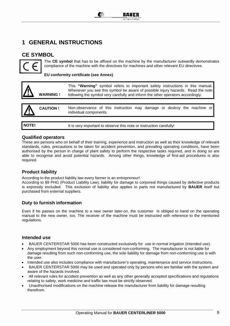
CE SYMBOL The CE symbol that has to be affixed on the machine by the manufacturer outwardly demonstrates compliance of the machine with the directives for machines and other relevant EU directives. EU conformity certificate (see Annex)
This “Warning” symbol refers to important safety instructions in this manual.
Whenever you see this symbol be aware of possible injury hazards. Read the note following the symbol very carefully and inform the other operators accordingly.
Non-observance of this instruction may damage or destroy the machine or individual components.
It is very important to observe this note or instruction carefully!
Qualified operators These are persons who on behalf of their training, experience and instruction as well as their knowledge of relevant standards, rules, precautions to be taken for accident prevention, and prevailing operating conditions, have been authorised by the person in charge of plant safety to perform the respective tasks required, and in doing so are able to recognise and avoid potential hazards. Among other things, knowledge of first-aid procedures is also required.
Product liability According to the product liability law every farmer is an entrepreneur! According to §9 PHG (Product Liability Law), liability for damage to corporeal things caused by defective products is expressly excluded. This exclusion of liability also applies to parts not manufactured by BAUER itself but purchased from external suppliers.
Duty to furnish information
Even if he passes on the machine to a new owner later-on, the customer is obliged to hand on the operating manual to the new owner, too. The receiver of the machine must be instructed with reference to the mentioned regulations.
Intended use • BAUER CENTERSTAR 5000 has been constructed exclusively for use in normal irrigation (intended use). • Any employment beyond this normal use is considered non-conforming. The manufacturer is not liable for
damage resulting from such non-conforming use, the sole liability for damage from non-conforming use is with the user.
• Intended use also includes compliance with manufacturer’s operating, maintenance and service instructions. • BAUER CENTERSTAR 5000 may be used and operated only by persons who are familiar with the system and
aware of the hazards involved. • All relevant rules for accident prevention as well as any other generally accepted specifications and regulations
relating to safety, work medicine and traffic law must be strictly observed. • Unauthorised modifications on the machine release the manufacturer from liability for damage resulting
therefrom.
WARNING !
CAUTION !
NOTE!
Operating Manual for BAUER CENTERLINER 5000 10
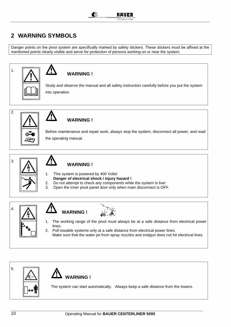
2 WARNING SYMBOLS Danger points on the pivot system are specifically marked by safety stickers. These stickers must be affixed at the mentioned points clearly visible and serve for protection of persons working on or near the system. 1.
WARNING !
Study and observe the manual and all safety instruction carefully before you put the system
into operation.
2.
WARNING !
Before maintenance and repair work, always stop the system, disconnect all power, and read
the operating manual.
3.
WARNING ! 1. This system is powered by 400 Volts!
Danger of electrical shock / injury hazard ! 2. Do not attempt to check any components while the system is live! 3. Open the inner pivot panel door only when main disconnect is OFF.
4.
WARNING ! 1. The working range of the pivot must always be at a safe distance from electrical power
lines. 2. Pull towable systems only at a safe distance from electrical power lines.
Make sure that the water jet from spray nozzles and endgun does not hit electrical lines.
5.
WARNING ! The system can start automatically. Always keep a safe distance from the towers.

Operating Manual for BAUER CENTERLINER 5000 11
6.
WARNING ! 1. Do not remove shaft guards. 2. When repair work is performed on the system, make sure that system cannot start
running automatically. Disconnect the complete system from power.
3 GENERAL BAUER CENTERLINER 5000 is an irrigation system consisting of a drive unit and boom elements (spans). The CENTERLINER is apt for rectangular or circle irrigation or a combination thereof. Depending on the model (CLS, CLE, CLX) different irrigation functions can be performed manually or fully automatic. All models are available non-towable and towable. Via hydrants and a flexible connection hose the systems are supplied with water. The four-wheel main cart is equipped with a Diesel generator unit, which supplies the power for the drive of the system; also mounted on the main cart is the control panel. The drive cart and the boom elements (towers, spans) are driven electrically. The joints (tower couplings) mounted between the spans allow horizontal and vertical angular deviation between the individual boom elements so that the system can adjust perfectly to the existing site conditions. Electric alignment controls between the spans control the horizontal angular deviation and ensure that the system runs in a straight line. Through varying spray nozzle set-ups and system speeds it is possible to tailor the water application exactly to all possible plant and soil requirements. The travel direction of the system is determined by a furrow drawn in the soil (furrow guidance) or a stretched cable (cable guidance).
4 GENERAL INSTRUCTIONS FOR SAFETY AND ACCIDENT PREVENTION
Check the operational safety of the machine before every star. 1. In addition to the instructions in this manual, be sure to observe all specifications generally valid for safety and
accident prevention! 2. The warning signs and notes affixed to the machine contain information essential to safe operation. Observing
them serves your own personal safety! 3. Do not start the machine unless all guards and safety devices are mounted completely and in proper working
position! 4. Acquaint yourself with all system components and controls as well as their respective functions, before you start
to work. It is too late for this when the system is already running! 5. Check the vicinity of the system before start-up (children!). Make sure that sight is unobstructed! 6. For towing, couple the device according to the instructions and fix it only at the prescribed devices! Electrical system check-up 1. Before the first start-up, check the electrical system and ensure that the installation complies with the safety
requirements. 2. Check the electrical system visually before every start-up. 3. All work beyond normal maintenance of the system is to be performed by a qualified service person only! 4. Never repair or service any part of the before all power has been disconnected! Maintenance - As a rule, maintenance and cleaning work as well as repairs of malfunctions may be done only with the drive
and the motor turned off! - Check proper seat of nuts and screws regularly, and tighten them, if needed! - Dispose of oil, grease, and filters in accordance with regulations. - Always disconnect system frompower before starting any work on the electrical system!
Operating Manual for BAUER CENTERLINER 5000 12
- Before electrical welding on the system itself or built-on components, disconnect the mains or generator supply cable!
- Spare parts must meet minimum technical requirements by the manufacturer of the device.! This is guaranteed by original equipment parts!
- 5 SAFETY PRECAUTIONS FOR CENTERLINER 5000 In addition to the GENERAL INSTRUCTIONS FOR SAFETY AND ACCIDENT PREVENTION, the following safety principles must be observed for operating BAUER – CENTERLINER 5000. ELECTRICAL SYSTEM
WARNING ! Since the system is powered by 400 V, always practice extreme caution when dealing with the electrical system and the electric drive !
1. All metal parts of the unit must be interconnected, all tower couplings must be bridged with a cable. 2. In addition the yellow-green marked protective conductor, which goes with the power supply, must be
connected to the protective conductor clamp in the control panel. 3. Before working on system electrical components, make sure the system is disconnected from all poles
and sources, and that generating unit is stopped.. 4. Provide a lock-out at the main disconnect to protect yourself against unintentional reclosing. 5. Verify safe isolation of electrical system. 6. Never repair or short-circuit a fuse by means of a wire or any other item. 7. Immediately repair or replace all wires with defective isolation. 8. Short-circuiting of system safety circuit is to be done only by a qualified person and only for the purpose
of realigning the system. MECHANICAL SYSTEM
WARNING ! 1. Never service or repair any part or system component while the plant is operating. 2. Always disconnect the system from power before starting any maintenance work. Turn the main
disconnect to „O“ and lock the switch to prevent unintentional reclosing and stop the generating unit. This disconnection needs to be done manually !
3. Before you start, make sure that all persons have left the operating range of the system. 4. Make sure that no objects or vehicles are in or near the system tracks when system is running/starting to
operate. 5. When the system is operating, the towers come on and off automatically. Keep a safe distance from the
towers. 6. Never step on the system while it is running. 7. Utmost care is required by the operator when spans are aligned. 8. Always turn off the system and water supply before working on sprinklers or spray nozzles. 9. Use adequate means of access (ladder, elevating platform) for work on sprinklers or spray nozzles. 10.Proceed with the utmost caution, when system is working near or under electric power lines, so that
neither the metal structure nor the water jets of sprinklers get in contact with live wires. 11.When towing movable systems, make sure that the system does not get in contact with a power line. 12.Make sure that not neighbouring plots or roads are wetted by the end gun. This could cause damage or
accidents. 13.If fertilisers or other chemicals are added to the irrigation water, avoid mist and do not inhale it.
Operating Manual for BAUER CENTERLINER 5000 13
6 TECHNICAL DESCRIPTION
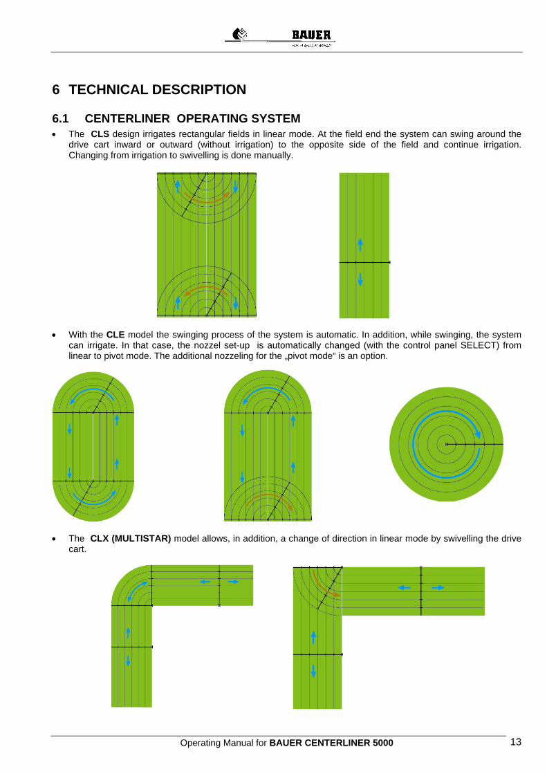
6.1 CENTERLINER OPERATING SYSTEM • The CLS design irrigates rectangular fields in linear mode. At the field end the system can swing around the
drive cart inward or outward (without irrigation) to the opposite side of the field and continue irrigation. Changing from irrigation to swivelling is done manually.
• With the CLE model the swinging process of the system is automatic. In addition, while swinging, the system
can irrigate. In that case, the nozzel set-up is automatically changed (with the control panel SELECT) from linear to pivot mode. The additional nozzeling for the „pivot mode“ is an option.
• The CLX (MULTISTAR) model allows, in addition, a change of direction in linear mode by swivelling the drive
cart.
Operating Manual for BAUER CENTERLINER 5000 14
6.2 COMPONENTS OF THE CENTERLINER
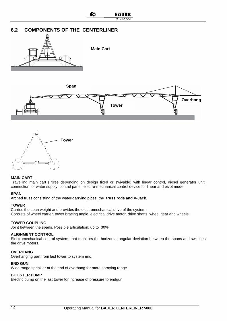
MAIN CART Travelling main cart ( tires depending on design fixed or swivable) with linear control, diesel generator unit, connection for water supply, control panel, electro-mechanical control device for linear and pivot mode.
SPAN Arched truss consisting of the water-carrying pipes, the truss rods and V-Jack.
TOWER Carries the span weight and provides the electromechanical drive of the system. Consists of wheel carrier, tower bracing angle, electrical drive motor, drive shafts, wheel gear and wheels. TOWER COUPLING Joint between the spans. Possible articulation: up to 30%.
ALIGNMENT CONTROL Electromechanical control system, that monitors the horizontal angular deviation between the spans and switches the drive motors. OVERHANG Overhanging part from last tower to system end.
END GUN Wide range sprinkler at the end of overhang for more spraying range
BOOSTER PUMP Electric pump on the last tower for increase of pressure to endgun
Main Cart
Tower
Span
Tower
Overhang
Operating Manual for BAUER CENTERLINER 5000 15
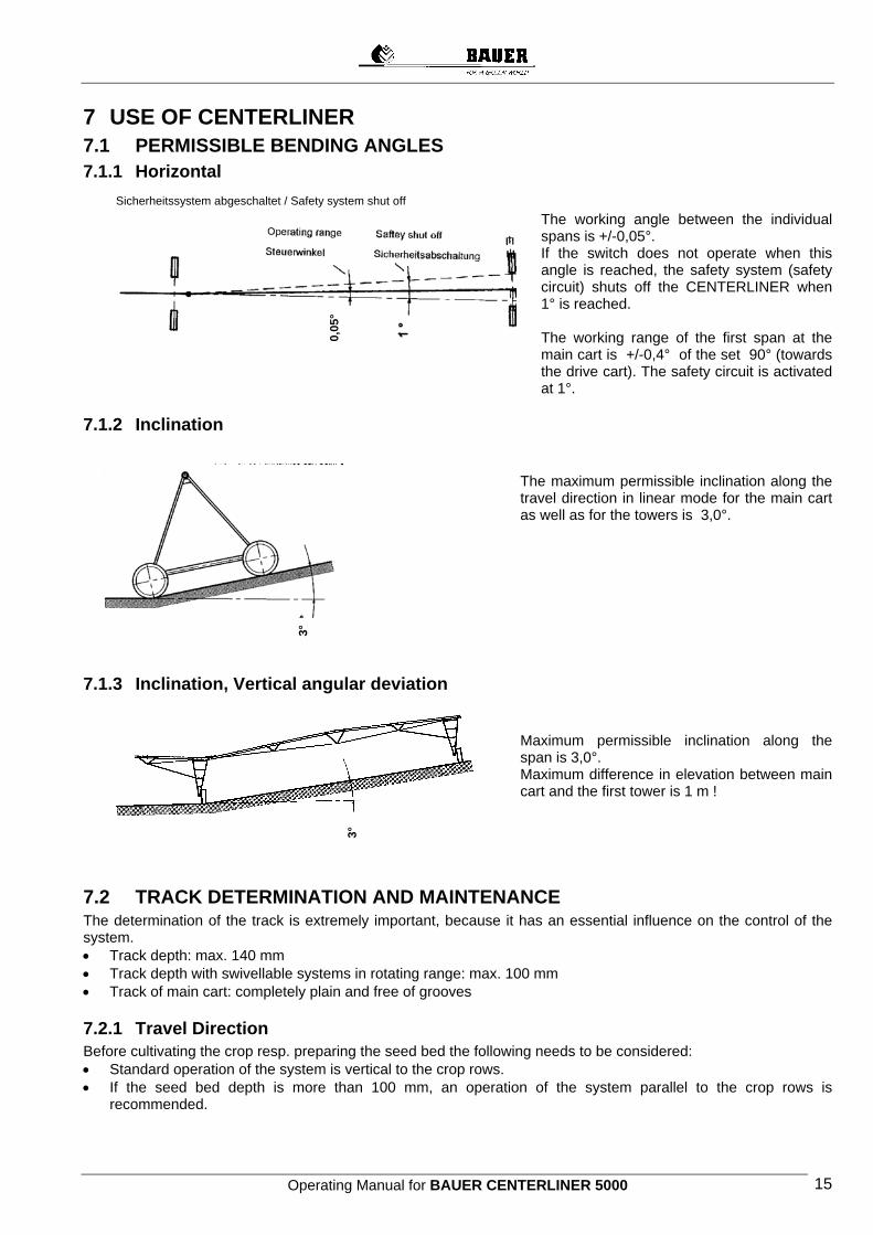
7 USE OF CENTERLINER 7.1 PERMISSIBLE BENDING ANGLES 7.1.1 Horizontal
The working angle between the individual spans is +/-0,05°. If the switch does not operate when this angle is reached, the safety system (safety circuit) shuts off the CENTERLINER when 1° is reached.
The working range of the first span at the main cart is +/-0,4° of the set 90° (towards the drive cart). The safety circuit is activated at 1°.
7.1.2 Inclination
The maximum permissible inclination along the travel direction in linear mode for the main cart as well as for the towers is 3,0°.
7.1.3 Inclination, Vertical angular deviation Maximum permissible inclination along the span is 3,0°. Maximum difference in elevation between main cart and the first tower is 1 m !
7.2 TRACK DETERMINATION AND MAINTENANCE The determination of the track is extremely important, because it has an essential influence on the control of the system. • Track depth: max. 140 mm • Track depth with swivellable systems in rotating range: max. 100 mm • Track of main cart: completely plain and free of grooves
7.2.1 Travel Direction Before cultivating the crop resp. preparing the seed bed the following needs to be considered: • Standard operation of the system is vertical to the crop rows. • If the seed bed depth is more than 100 mm, an operation of the system parallel to the crop rows is
recommended.
3°
0,05
° 3°
Sicherheitssystem abgeschaltet / Safety system shut off
Operating Manual for BAUER CENTERLINER 5000 16
If it is required to operate the system parallel to the crop rows, apply one of the following methods to determine the track. Method I 1. Before cultivating run „dry“ along the entire field. That way the tracks are determined. 2. Use these tracks as guidance for the crop row to be cultivated.
The distance of the first crop rows to the left and the right of the track shall be 250 mm. Method II 1. Plant the entire field parallel to the system‘s travel direction. 2. Run „dry“ along the entire field. 3. Level out the crop rows 250 mm to the left and the right of the tracks. That way deep tracks and cracks
between the crop rows can be prevented. An exact run of the system is guaranteed.
Instructions for determining tracks 1. Run once "dry" with timer setting of 100 % over the entire field. 2. A second time run "wet" with timer setting 80 - 90 % over the entire field. Subsequent operation of the system as desired. If the tracks become too deep, these need to be levelled out or filled up. Then run the system dry with timer setting 100 % over the entire field. The reverse run „wet“ with the same timer setting.
8 CENTERLINER MAIN CART
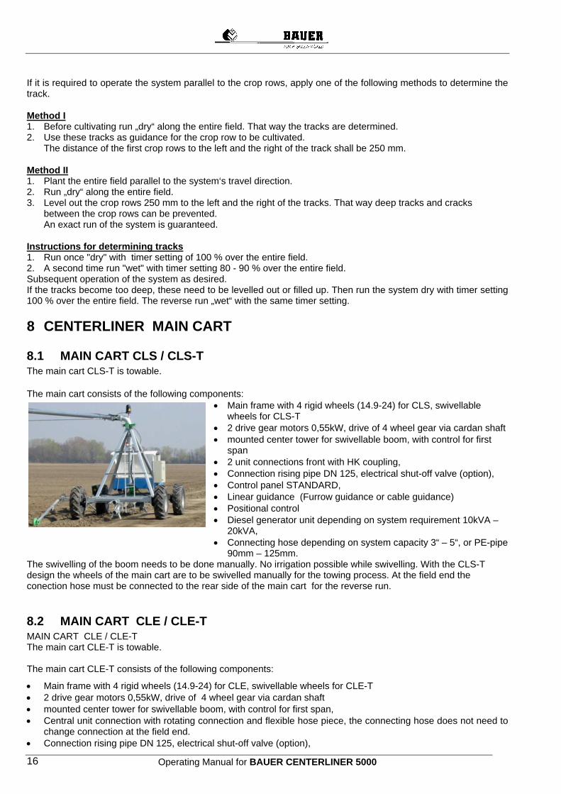
8.1 MAIN CART CLS / CLS-T The main cart CLS-T is towable. The main cart consists of the following components:
• Main frame with 4 rigid wheels (14.9-24) for CLS, swivellable wheels for CLS-T
• 2 drive gear motors 0,55kW, drive of 4 wheel gear via cardan shaft • mounted center tower for swivellable boom, with control for first
span • 2 unit connections front with HK coupling, • Connection rising pipe DN 125, electrical shut-off valve (option), • Control panel STANDARD, • Linear guidance (Furrow guidance or cable guidance) • Positional control • Diesel generator unit depending on system requirement 10kVA –
20kVA, • Connecting hose depending on system capacity 3“ – 5“, or PE-pipe
90mm – 125mm. The swivelling of the boom needs to be done manually. No irrigation possible while swivelling. With the CLS-T design the wheels of the main cart are to be swivelled manually for the towing process. At the field end the conection hose must be connected to the rear side of the main cart for the reverse run.
8.2 MAIN CART CLE / CLE-T MAIN CART CLE / CLE-T The main cart CLE-T is towable. The main cart CLE-T consists of the following components:
• Main frame with 4 rigid wheels (14.9-24) for CLE, swivellable wheels for CLE-T • 2 drive gear motors 0,55kW, drive of 4 wheel gear via cardan shaft • mounted center tower for swivellable boom, with control for first span, • Central unit connection with rotating connection and flexible hose piece, the connecting hose does not need to
change connection at the field end. • Connection rising pipe DN 125, electrical shut-off valve (option),
Operating Manual for BAUER CENTERLINER 5000 17
• Control panel SELECT or PRO, • Linear control (Furrow guidance or cable guidance) • Positional control • Diesel generator unit depending on system requirement 10kVA – 20kVA, • Connecting hose depending on system capacity 3“ – 5“, or PE-pipe 90mm – 125mm. The swivelling of the boom is automatic. While swivelling, irrigation is possible with respective nozzeling. With the CLE-T design swivel the wheels of the main cart manually. At the field end the connection of the connecting hose on the main cart does not need to be changed for the reverse run.
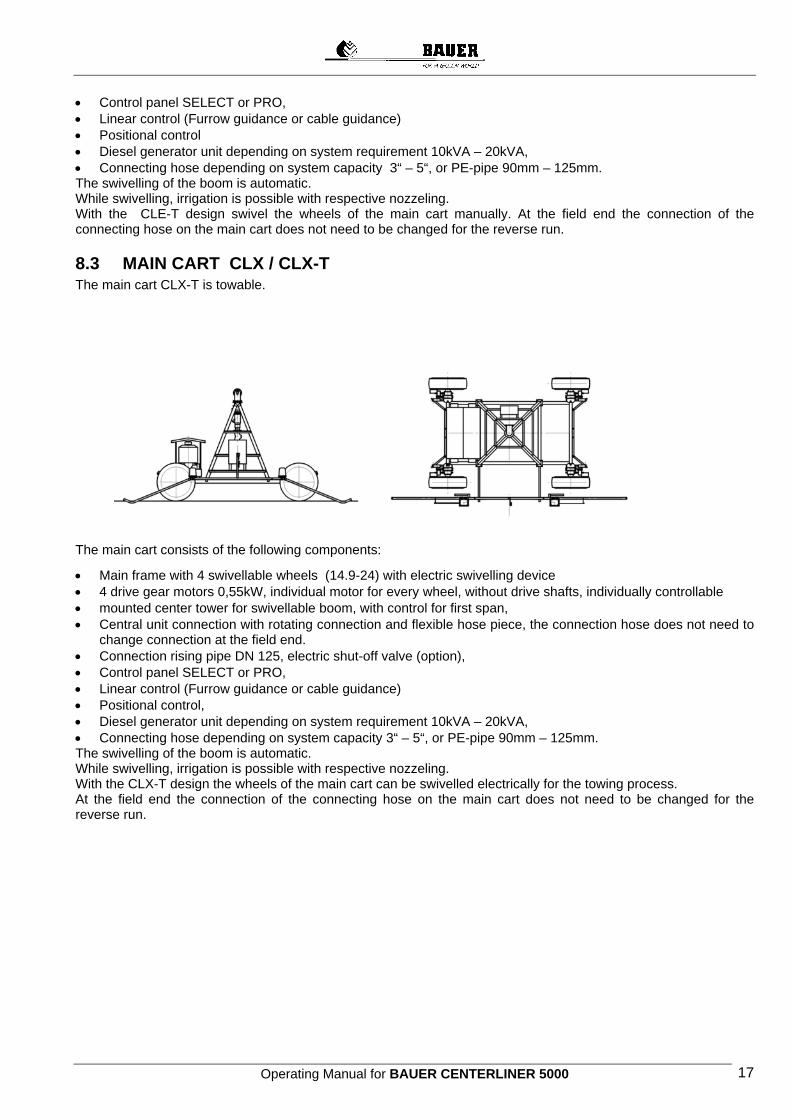
8.3 MAIN CART CLX / CLX-T The main cart CLX-T is towable.
The main cart consists of the following components:
• Main frame with 4 swivellable wheels (14.9-24) with electric swivelling device • 4 drive gear motors 0,55kW, individual motor for every wheel, without drive shafts, individually controllable • mounted center tower for swivellable boom, with control for first span, • Central unit connection with rotating connection and flexible hose piece, the connection hose does not need to
change connection at the field end. • Connection rising pipe DN 125, electric shut-off valve (option), • Control panel SELECT or PRO, • Linear control (Furrow guidance or cable guidance) • Positional control, • Diesel generator unit depending on system requirement 10kVA – 20kVA, • Connecting hose depending on system capacity 3“ – 5“, or PE-pipe 90mm – 125mm. The swivelling of the boom is automatic. While swivelling, irrigation is possible with respective nozzeling. With the CLX-T design the wheels of the main cart can be swivelled electrically for the towing process. At the field end the connection of the connecting hose on the main cart does not need to be changed for the reverse run.
Operating Manual for BAUER CENTERLINER 5000 18
9 CONTROL PANEL To protect against pollution and splash water make sure the control panel is always
closed during operation.
• Water-proof sheet steel box (system of protection IP 54) with lockable front door
• With corrosion-resistant coating • Hinged operating panel, can only be opened, if main power switch is turned off
. • System operating voltage 400 V • Driving voltage: 220 V one phase • Isolating transformer for the driving voltage • Industrial switch gear usual in the trade • Cable connection with cable brackets • Protection devices
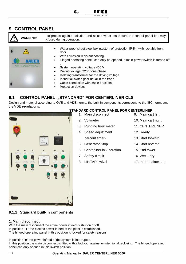
9.1 CONTROL PANEL „STANDARD“ FOR CENTERLINER CLS Design and material according to ÖVE and VDE norms, the built-in components correspond to the IEC norms and the VDE regulations.
STANDARD CONTROL PANEL FOR CENTERLINER
1. Main disconnect
2. Voltmeter
3. Running hour meter
4. Speed adjustment
percent timer)
5. Generator Stop
6. Centerliner in Operation
7. Safety circuit
8. LINEAR swivel
9. Main cart left
10. Main cart right
11. CENTERLINER
12. Ready
13. Start forward
14. Start reverse
15. End tower
16. Wet – dry
17. Intermediate stop
9.1.1 Standard built-in components 1. Main disconnect With the main disconnect the entire power infeed is shut on or off. In position " I " the electric power infeed of the plant is established. The hinged operating panel in this position is locked for safety reasons. In position “0“ the power infeed of the system is interrupted. In this position the main disconnect is fitted with a lock-out against unintentional reclosing. The hinged operating panel can only opened in this switch position.
WARNING!
Operating Manual for BAUER CENTERLINER 5000 19
2. Voltmeter Shows the voltage between phases L1 and L2. 3. Running hour meter Shows the total hours the system has operated. 4. Percent timer "SPEED" With the percent timer the running time of the end tower per minute is set and thus the running speed of the system regulated. This means, a setting of the rotating switch at 50%, that the end tower operates for 30 seconds and rests for 30 seconds. The running speed of the system thus is 50 % of the maximum speed. A re-set is possible at any time during the run. 5. Switch „GENERATOR STOP OFF – ON“ ON The generator unit switches off automatically:
• When the system runs into the safety circuit. • At a pressure drop in the supply line . • At the end stop • At an intermediate stop, e.g. to change the connection of the supply hose. • Use this setting during a regular run !
OFF In this position the generator unit does not switch off in the cases mentioned above.
This setting is used • When aligning the towers. • When operating the system without water.
6. Visual indication "CENTERLINER IN OPERATION" Indication appears, when all controlling means for linear mode are in operating position, are ready for operation. 7. Switch „SAFETY CIRCUIT ON - OFF“ ON In this position, when there is a malfunction (e.g. doglegging), the entire system will shut off. OFF This position serves exclusively for the system alignment through a qualified person. This switch MUST always be ON while the system is operating !!
This is the only way to ensure a safe operation unattended !
8. Switch „LINEAR - SWIVEL“ LINEAR For the linear operation of the unit. With or without irrigation. SWIVEL Setting to swivel the system at the field end.
9. / 10. Push button „CENTER TOWER LEFT“ „CENTER TOWER RIGHT“ By pressing this button, the right and left wheel pair of the main cart start operating. The main cart can be set parallel to the control furrow or the control cable. By pressing both buttons, the entire main cart goes forward or back.
11. Switch „CENTERLINER ON – OFF“ The entire operating system of the CENTERLINER is switched on and off with this switch.
12. Visual/illuminated indication „READY“ This gets illuminated, when all operating conditions of the CENTERLINER are met. The system is aligned, infeed operating pressure given etc.
13. / 14. Switch „START FORWARD“ „START REVERSE“ To set the running direction of the system. For linear and swivel operation.
Operating Manual for BAUER CENTERLINER 5000 20
15. Push button „END TOWER“ The end tower can be moved into the preselected direction.
16. Switch „WET-DRY“ In „WET“ position the system is shut down by means of a pressure switch mounted on the infeed water pipe (option), as soon as the pressure limit falls below the limit. The „DRY“ position allows to run the systm dry (e.g. if the CENTERLINER has to be returned to its parking position dry without irrigation). The valve of the supply line is closed.
NOTE ! The „WET-DRY“ switch is only effective in combination with the optional pressure switch!
17. Switch „INTERMEDIATE STOP ON-OFF“ In „ON“ position the CENTERLINER is shut down in a desired position (e.g. between two hydrants to change the connection of the connecting hose) with the help of a switching peg. In „OFF“ position the CENTERLINER passes by this switching point. NOTE : For control panel „SELECT“ separate operating instructions.
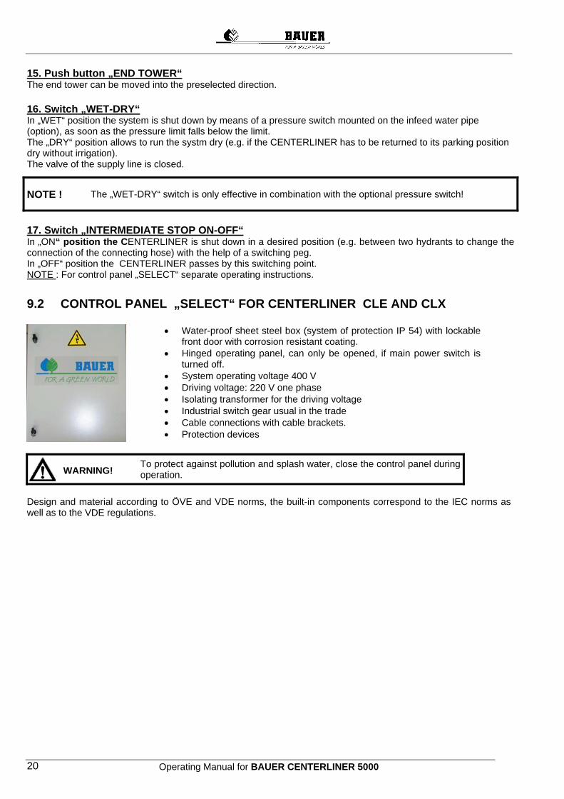
9.2 CONTROL PANEL „SELECT“ FOR CENTERLINER CLE AND CLX
• Water-proof sheet steel box (system of protection IP 54) with lockable front door with corrosion resistant coating.
• Hinged operating panel, can only be opened, if main power switch is turned off.
• System operating voltage 400 V • Driving voltage: 220 V one phase • Isolating transformer for the driving voltage • Industrial switch gear usual in the trade • Cable connections with cable brackets. • Protection devices
To protect against pollution and splash water, close the control panel during
operation.
Design and material according to ÖVE and VDE norms, the built-in components correspond to the IEC norms as well as to the VDE regulations.
WARNING!

Operating Manual for BAUER CENTERLINER 5000 21
9.2.1 Switch and control elements of the control panel „Select“ 1. Running hour meter 2. Voltmeter 3. Main disconnect 4. Speed 1
Linear mode 5. Speed 2
Linear mode 6. Speed
Pivot mode 7. Linear mode 8. Ready 9. Center tower in operation 10. End tower in operation 11. Centerliner ON OFF 12. Safety circuit ON OFF 13. Generator Stop ON OFF 14. Wet Dry 15. Intermediate stop ON OFF 16. Start forward 17. Start Reverse 18. STOP 19. Program Option switch
20. to 23. Motor Option switch (only with CLX)
1. Running hour meter Shows the total hours the system has operated. 2. Voltmeter Shows the voltages between phases L1 and L2. 3. Main disconnect With the main disconnect the entire power infeed is shut on or off. In position " I " the electric power infeed of the plant is established. The hinged operating panel in this position is locked for safety reasons. In position “0“ the power infeed to the system is interrupted. In this position the main disconnect is fitted with a lock-out against unintentional reclosing. The hinged operating panel can only be opened in this switch position. 4. Speed 1 Linear mode With Speed 1 Linear mode, the running speed of the system in linear mode can be set. Setting the rotating button to 50 % means that the end tower within one minute operates 30 seconds and then rests. The speed of the system thus is 50 % of the maximum speed. Re-setting during operation is possible at any time. 5. Speed 2 Linear mode With Speed 2 Linear mode a different speed for the system can be selected for a secod running section
2
3
7
9
11
14
16
20
19
1
8
12 13
15
17
21 22 23
18
10
5 6
4
Operating Manual for BAUER CENTERLINER 5000 22
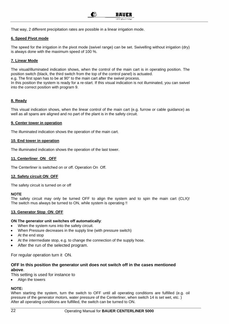
That way, 2 different precipitation rates are possible in a linear irrigation mode. 6. Speed Pivot mode The speed for the irrigation in the pivot mode (swivel range) can be set. Swivelling without irrigation (dry) is always done with the maximum speed of 100 %. 7. Linear Mode The visual/illuminated indication shows, when the control of the main cart is in operating position. The position switch (black, the third switch from the top of the control panel) is actuated. e.g. The first span has to be at 90° to the main cart after the swivel process. In this position the system is ready for a re-start. If this visual indication is not illuminated, you can swivel into the correct position with program 9. 8. Ready This visual indication shows, when the linear control of the main cart (e.g. furrow or cable guidance) as well as all spans are aligned and no part of the plant is in the safety circuit. 9. Center tower in operation The illuminated indication shows the operation of the main cart. 10. End tower in operation The illuminated indication shows the operation of the last tower. 11. Centerliner ON OFF The Centerliner is switched on or off. Operation On Off. 12. Safety circuit ON OFF The safety circuit is turned on or off NOTE The safety circuit may only be turned OFF to align the system and to spin the main cart (CLX)! The switch mus always be turned to ON, while system is operating !! 13. Generator Stop ON OFF ON The generator unit switches off automatically: • When the system runs into the safety circuit. • When Pressure decreases in the supply line (with pressure switch) • At the end stop • At the intermediate stop, e.g. to change the connection of the supply hose. • After the run of the selected program. For regular operation turn it ON. OFF In this position the generator unit does not switch off in the cases mentioned above. This setting is used for instance to • Align the towers NOTE: When starting the system, turn the switch to OFF until all operating conditions are fulfilled (e.g. oil pressure of the generator motors, water pressure of the Centerliner, when switch 14 is set wet, etc. ) After all operating conditions are fulfilled, the switch can be turned to ON.
Operating Manual for BAUER CENTERLINER 5000 23
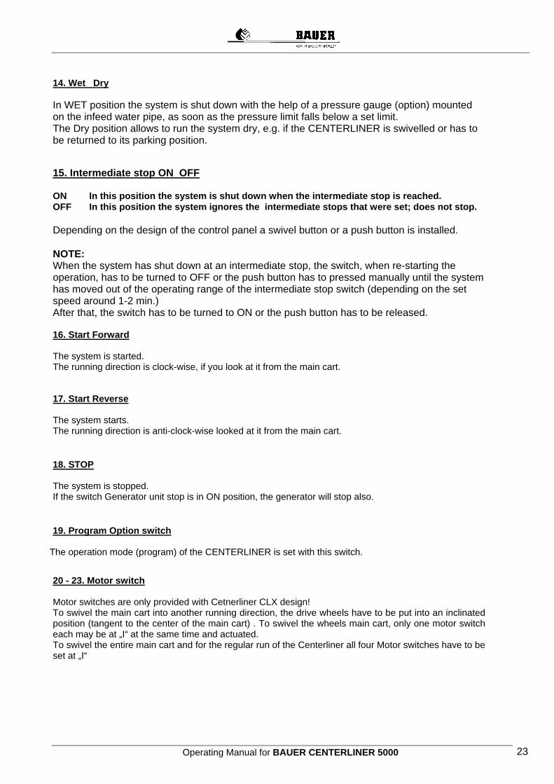
14. Wet Dry In WET position the system is shut down with the help of a pressure gauge (option) mounted on the infeed water pipe, as soon as the pressure limit falls below a set limit. The Dry position allows to run the system dry, e.g. if the CENTERLINER is swivelled or has to be returned to its parking position.
15. Intermediate stop ON OFF ON In this position the system is shut down when the intermediate stop is reached. OFF In this position the system ignores the intermediate stops that were set; does not stop. Depending on the design of the control panel a swivel button or a push button is installed. NOTE: When the system has shut down at an intermediate stop, the switch, when re-starting the operation, has to be turned to OFF or the push button has to pressed manually until the system has moved out of the operating range of the intermediate stop switch (depending on the set speed around 1-2 min.) After that, the switch has to be turned to ON or the push button has to be released. 16. Start Forward The system is started. The running direction is clock-wise, if you look at it from the main cart.
17. Start Reverse The system starts. The running direction is anti-clock-wise looked at it from the main cart.
18. STOP The system is stopped. If the switch Generator unit stop is in ON position, the generator will stop also.
19. Program Option switch
The operation mode (program) of the CENTERLINER is set with this switch.
20 - 23. Motor switch Motor switches are only provided with Cetnerliner CLX design! To swivel the main cart into another running direction, the drive wheels have to be put into an inclinated position (tangent to the center of the main cart) . To swivel the wheels main cart, only one motor switch each may be at „I“ at the same time and actuated. To swivel the entire main cart and for the regular run of the Centerliner all four Motor switches have to be set at „I“
Operating Manual for BAUER CENTERLINER 5000 24
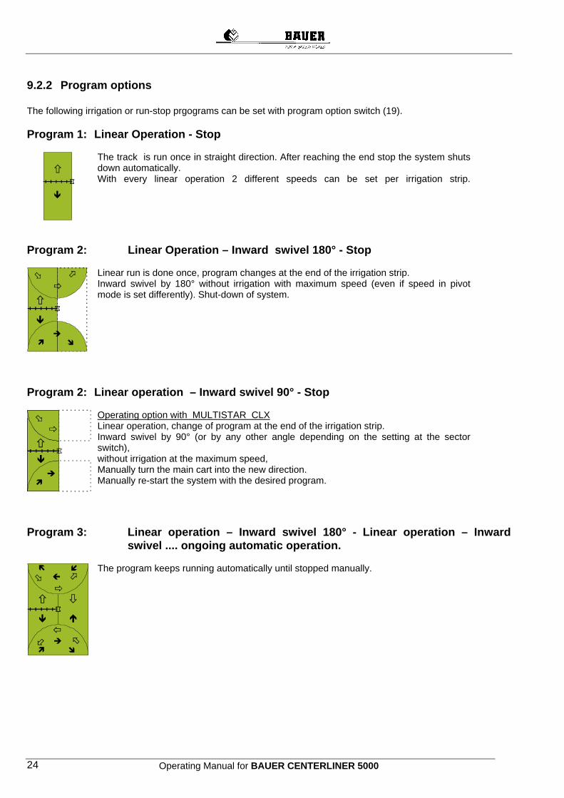
9.2.2 Program options The following irrigation or run-stop prgograms can be set with program option switch (19). Program 1: Linear Operation - Stop
The track is run once in straight direction. After reaching the end stop the system shuts down automatically. With every linear operation 2 different speeds can be set per irrigation strip.
Program 2: Linear Operation – Inward swivel 180° - Stop
Linear run is done once, program changes at the end of the irrigation strip. Inward swivel by 180° without irrigation with maximum speed (even if speed in pivot mode is set differently). Shut-down of system.
Program 2: Linear operation – Inward swivel 90° - Stop
Operating option with MULTISTAR CLX Linear operation, change of program at the end of the irrigation strip. Inward swivel by 90° (or by any other angle depending on the setting at the sector switch), without irrigation at the maximum speed, Manually turn the main cart into the new direction. Manually re-start the system with the desired program.
Program 3: Linear operation – Inward swivel 180° - Linear operation – Inward
swivel .... ongoing automatic operation.
The program keeps running automatically until stopped manually.
Operating Manual for BAUER CENTERLINER 5000 25
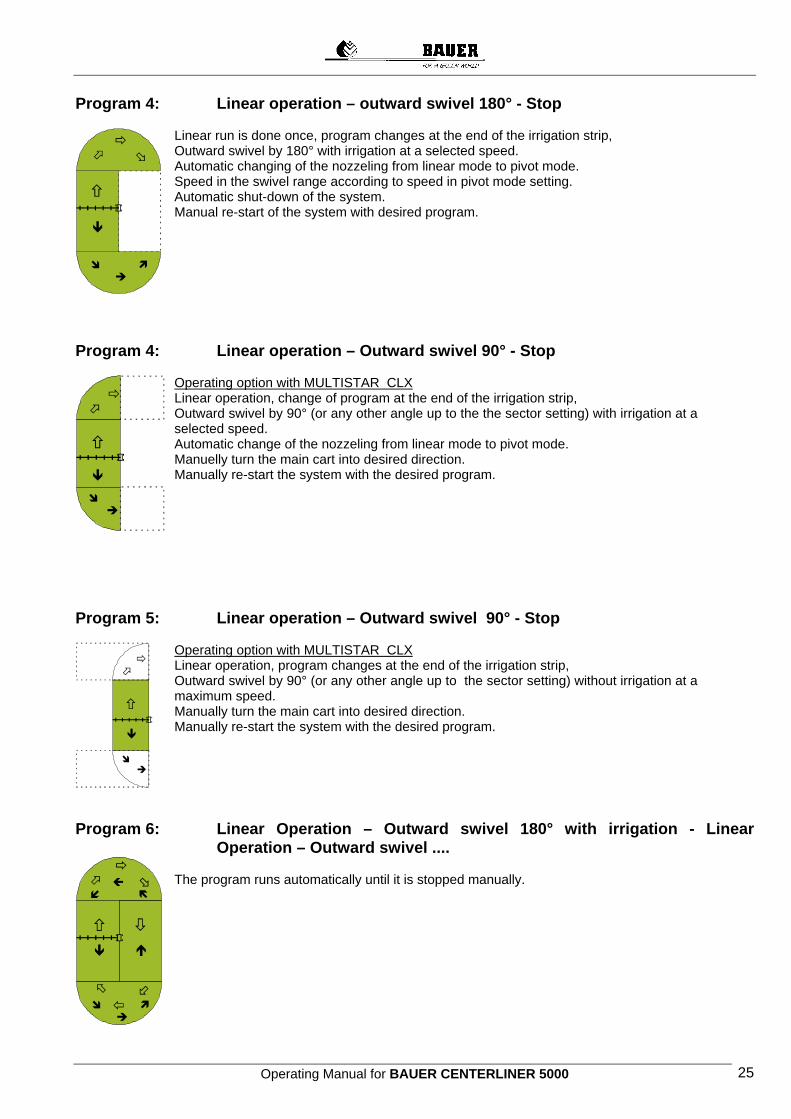
Program 4: Linear operation – outward swivel 180° - Stop
Linear run is done once, program changes at the end of the irrigation strip, Outward swivel by 180° with irrigation at a selected speed. Automatic changing of the nozzeling from linear mode to pivot mode. Speed in the swivel range according to speed in pivot mode setting. Automatic shut-down of the system. Manual re-start of the system with desired program.
Program 4: Linear operation – Outward swivel 90° - Stop
Operating option with MULTISTAR CLX Linear operation, change of program at the end of the irrigation strip, Outward swivel by 90° (or any other angle up to the the sector setting) with irrigation at a selected speed. Automatic change of the nozzeling from linear mode to pivot mode. Manuelly turn the main cart into desired direction. Manually re-start the system with the desired program.
Program 5: Linear operation – Outward swivel 90° - Stop
Operating option with MULTISTAR CLX Linear operation, program changes at the end of the irrigation strip, Outward swivel by 90° (or any other angle up to the sector setting) without irrigation at a maximum speed. Manually turn the main cart into desired direction. Manually re-start the system with the desired program.
Program 6: Linear Operation – Outward swivel 180° with irrigation - Linear
Operation – Outward swivel ....
The program runs automatically until it is stopped manually.
Operating Manual for BAUER CENTERLINER 5000 26
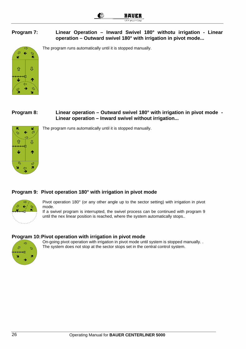
Program 7: Linear Operation – Inward Swivel 180° withotu irrigation - Linear operation – Outward swivel 180° with irrigation in pivot mode...
The program runs automatically until it is stopped manually.
Program 8: Linear operation – Outward swivel 180° with irrigation in pivot mode -
Linear operation – Inward swivel without irrigation...
The program runs automatically until it is stopped manually.
Program 9: Pivot operation 180° with irrigation in pivot mode
Pivot operation 180° (or any other angle up to the sector setting) with irrigation in pivot mode. If a swivel program is interrupted, the swivel process can be continued with program 9 until the nex linear position is reached, where the system automatically stops..
Program 10: Pivot operation with irrigation in pivot mode
On-going pivot operation with irrigation in pivot mode until system is stopped manually. . The system does not stop at the sector stops set in the central control system.
Operating Manual for BAUER CENTERLINER 5000 27
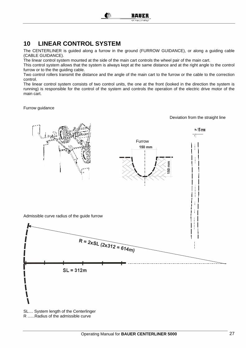
10 LINEAR CONTROL SYSTEM The CENTERLINER is guided along a furrow in the ground (FURROW GUIDANCE), or along a guiding cable (CABLE GUIDANCE). The linear control system mounted at the side of the main cart controls the wheel pair of the main cart. This control system allows that the system is always kept at the same distance and at the right angle to the control furrow or to the the guiding cable. Two control rollers transmit the distance and the angle of the main cart to the furrow or the cable to the correction control. The linear control system consists of two control units, the one at the front (looked in the direction the system is running) is responsible for the control of the system and controls the operation of the electric drive motor of the main cart. Furrow guidance
Deviation from the straight line Furrow
Admissible curve radius of the guide furrow
SL.... System length of the Centerlinger R ......Radius of the admissible curve

Operating Manual for BAUER CENTERLINER 5000 28
Guiding cable
Length of Field
Path
10.1 SETTING LINEAR CONTROL Before starting, adjust the linear control system such, that the main cart in both directions runs parallel and at the same distance to the guiding cable or the guiding furrow. The setting of the switch points for furrow and cable guidance is basically the same.
Linear Control Units Guiding Arms Skid or Cable Roll Guiding FurrowRespectivelyGuiding Cable
Operating Manual for BAUER CENTERLINER 5000 29
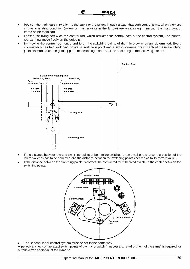
• Position the main cart in relation to the cable or the furrow in such a way, that both control arms, when they are in their operating condition (rollers on the cable or in the furrow) are on a straight line with the fixed control frame of the main cart.
• Loosen the fixing screw on the control rod, which actuates the control cam of the control system, The control rod can now move freely on the guide pin.
• By moving the control rod hence and forth, the switching points of the micro-switches are determined. Every micro-switch has two switching points, a switch-on point and a switch-reverse point. Each of these switching points is marked on the guiding pin. The switching points shall be according to the following sketch:
• If the distance between the end switching points of both micro-switches is too small or too large, the position of the
micro switches has to be corrected and the distance between the switching points checked as to its correct value. • If the distance between the switching points is correct, the control rod must be fixed exactly in the center between the
switching points.
• The second linear control system must be set in the same way. A periodical check of the exact switch points of the micro-switch (if necessary, re-adjustment of the same) is required for a trouble-free operation of the machine.
Guiding Arm
Switching Rod
Fixing Bolt
Fixation of Switching Rod Reversing Point Reversing
Point Switching Point Switching Point
Terminal Strip
Safety Switch
Safety Switch
Switching Cam
Safety Switch
Operating Manual for BAUER CENTERLINER 5000 30
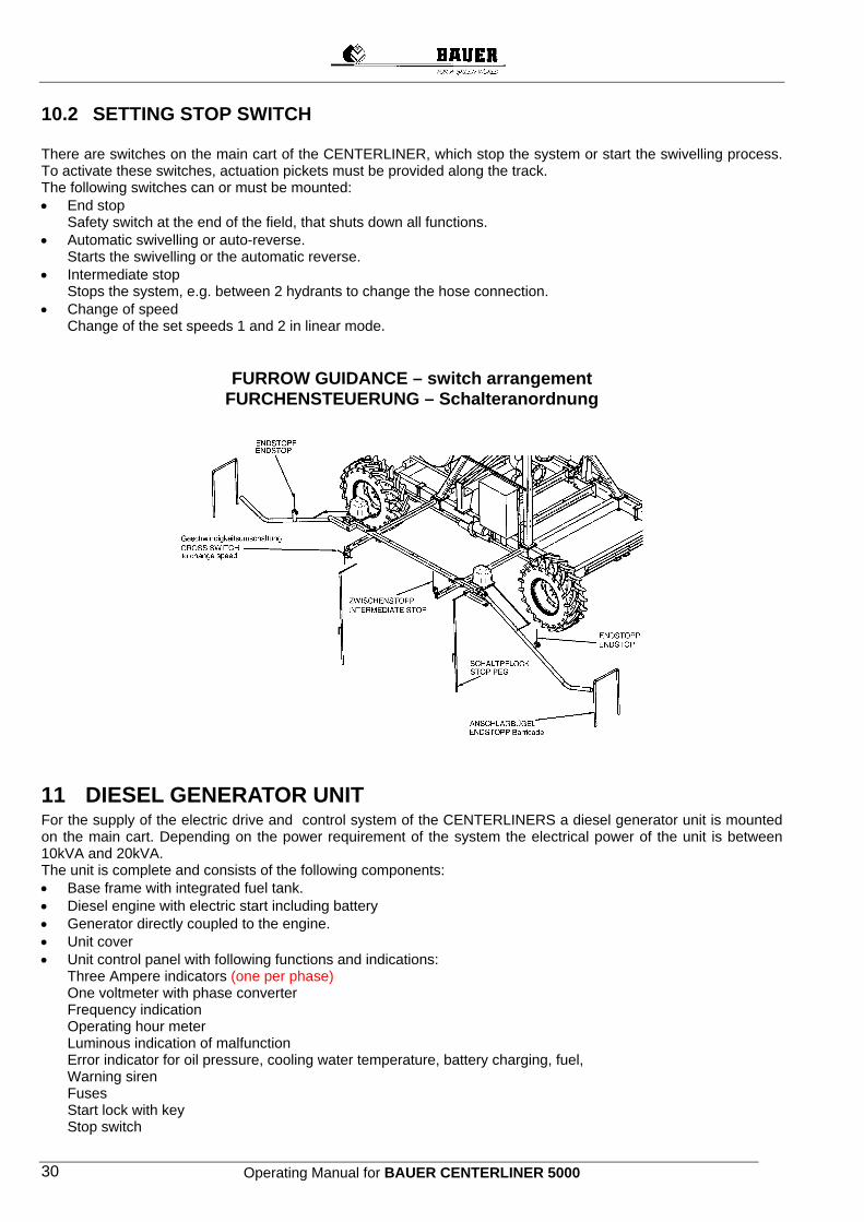
10.2 SETTING STOP SWITCH There are switches on the main cart of the CENTERLINER, which stop the system or start the swivelling process. To activate these switches, actuation pickets must be provided along the track. The following switches can or must be mounted: • End stop
Safety switch at the end of the field, that shuts down all functions. • Automatic swivelling or auto-reverse.
Starts the swivelling or the automatic reverse. • Intermediate stop
Stops the system, e.g. between 2 hydrants to change the hose connection. • Change of speed
Change of the set speeds 1 and 2 in linear mode.
FURROW GUIDANCE – switch arrangement FURCHENSTEUERUNG – Schalteranordnung
11 DIESEL GENERATOR UNIT For the supply of the electric drive and control system of the CENTERLINERS a diesel generator unit is mounted on the main cart. Depending on the power requirement of the system the electrical power of the unit is between 10kVA and 20kVA. The unit is complete and consists of the following components: • Base frame with integrated fuel tank. • Diesel engine with electric start including battery • Generator directly coupled to the engine. • Unit cover • Unit control panel with following functions and indications:
Three Ampere indicators (one per phase) One voltmeter with phase converter Frequency indication Operating hour meter Luminous indication of malfunction Error indicator for oil pressure, cooling water temperature, battery charging, fuel, Warning siren Fuses Start lock with key Stop switch
Operating Manual for BAUER CENTERLINER 5000 31
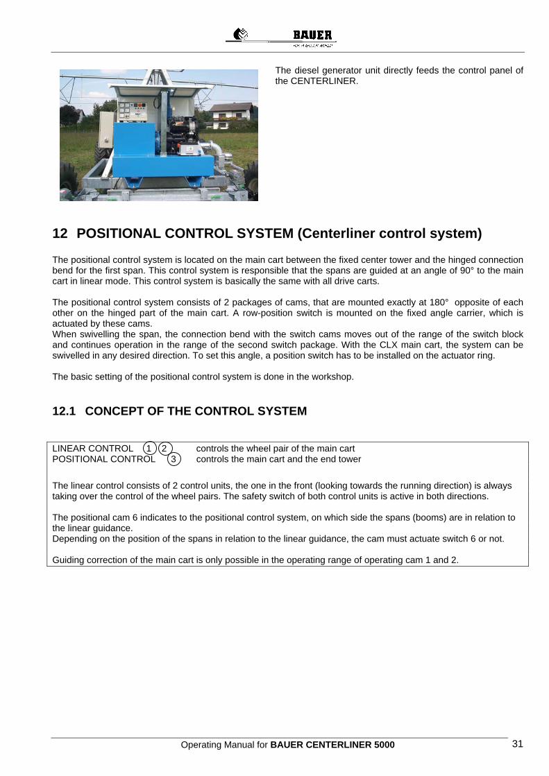
The diesel generator unit directly feeds the control panel of the CENTERLINER.
12 POSITIONAL CONTROL SYSTEM (Centerliner control system) The positional control system is located on the main cart between the fixed center tower and the hinged connection bend for the first span. This control system is responsible that the spans are guided at an angle of 90° to the main cart in linear mode. This control system is basically the same with all drive carts. The positional control system consists of 2 packages of cams, that are mounted exactly at 180° opposite of each other on the hinged part of the main cart. A row-position switch is mounted on the fixed angle carrier, which is actuated by these cams. When swivelling the span, the connection bend with the switch cams moves out of the range of the switch block and continues operation in the range of the second switch package. With the CLX main cart, the system can be swivelled in any desired direction. To set this angle, a position switch has to be installed on the actuator ring. The basic setting of the positional control system is done in the workshop.
12.1 CONCEPT OF THE CONTROL SYSTEM LINEAR CONTROL 1 2 controls the wheel pair of the main cart POSITIONAL CONTROL 3 controls the main cart and the end tower
The linear control consists of 2 control units, the one in the front (looking towards the running direction) is always taking over the control of the wheel pairs. The safety switch of both control units is active in both directions. The positional cam 6 indicates to the positional control system, on which side the spans (booms) are in relation to the linear guidance. Depending on the position of the spans in relation to the linear guidance, the cam must actuate switch 6 or not. Guiding correction of the main cart is only possible in the operating range of operating cam 1 and 2.
Operating Manual for BAUER CENTERLINER 5000 32
12.1.1 Linear guidance inside of the main cart
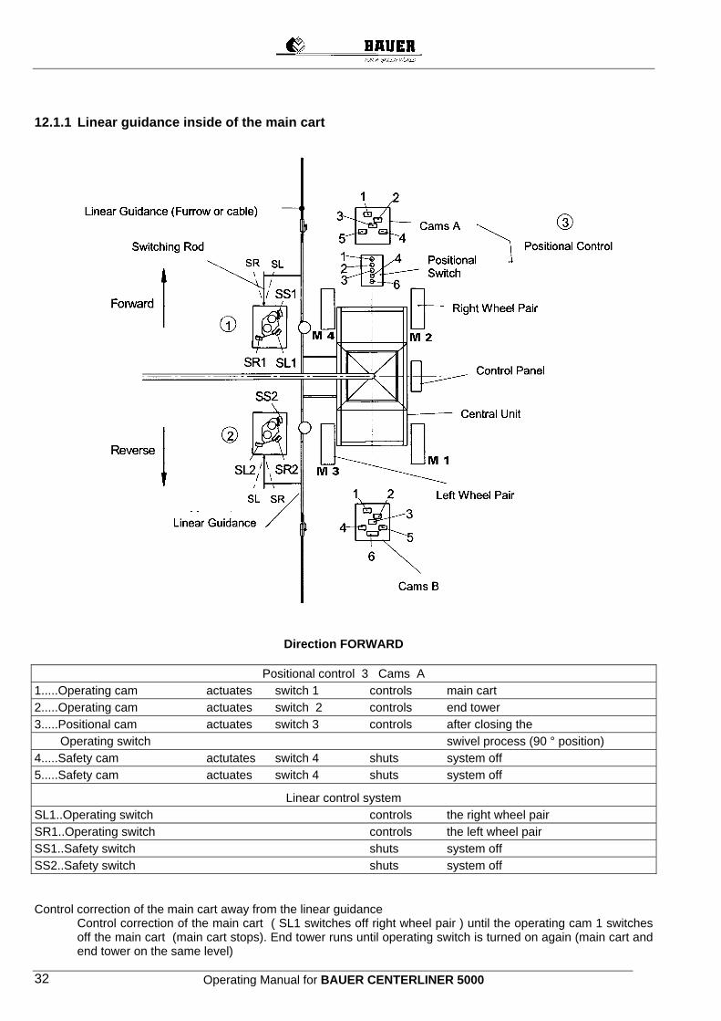
Direction FORWARD
Positional control 3 Cams A 1.....Operating cam actuates switch 1 controls main cart 2.....Operating cam actuates switch 2 controls end tower 3.....Positional cam actuates switch 3 controls after closing the Operating switch swivel process (90 ° position) 4.....Safety cam actutates switch 4 shuts system off 5.....Safety cam actuates switch 4 shuts system off
Linear control system SL1..Operating switch controls the right wheel pair SR1..Operating switch controls the left wheel pair SS1..Safety switch shuts system off SS2..Safety switch shuts system off Control correction of the main cart away from the linear guidance
Control correction of the main cart ( SL1 switches off right wheel pair ) until the operating cam 1 switches off the main cart (main cart stops). End tower runs until operating switch is turned on again (main cart and end tower on the same level)
Operating Manual for BAUER CENTERLINER 5000 33
Only then, a further control correction of the main cart or the linear run is possible. Control correction of the main cart towards the linear guidance
Control correction of the main cart (SR1 switches off left wheel pair) until operating cam 2 turns off the end tower. Main cart (4 wheel) continues its run until operating cam 2 re-starts the end tower. Only then, a further control correction of the main cart or linear run is possible (control correction of the main cart only possible, when end tower is running)
As the main cart approaches the linear guidance in a bow-shape, we have a situation, in which a control correction of the main cart away from the linear guidance is required. This control correction of the main cart is also possible with the end tower turned off.
Direction REVERSE
Positional control 3 Cams A 1.....Operating cam actuates switch 1 controls end tower 2.....Operating cam actuates switch 2 controls main cart 3.....Positional cam actuates switch 3 switches after closing the Operating switch swivel process (90 ° position) 4.....Safety cam actuates switch 4 shuts system off 5.....Safety cam actuates switch 4 shuts system off
Linear control 2 SL2..Operating switch controls left wheel pair SR2..Operating switch controls right wheel pair SS2..Safety switch shuts system off SS1..Safety switch shuts system off Control correction of the main cart away from the linear guidance
Control correction of the main cart (SR2 shuts down right wheel pair) until the operating cam 2 shuts off the main cart (main cart stops) End tower continues running until operating switch 2 is switched on again (Main cart and End tower on the same level) / Only then a further control correction of the main cart or the linear guidance is possible.
MC....Main cart
ET....End tower Control correction of the main cart towards the linear guidance. Control correction of the main cart (SL2 switches off the left wheel pair) until the operating cam 1 turns off the end tower. Main cart (4 wheels) continues to run until the operating cam 1 restarts the end tower. Only then a further correction of the main cart or the linear guidance is possible. (Control correction of the
main cart only possible, when end tower runs) As the main cart approaches the linear guidance in a bow-shape, we have a situation, where a control correction of the main cart away from the linear guidance is necessary. This correction of the main cart is also possible, if the end tower is turned off.
Operating Manual for BAUER CENTERLINER 5000 34
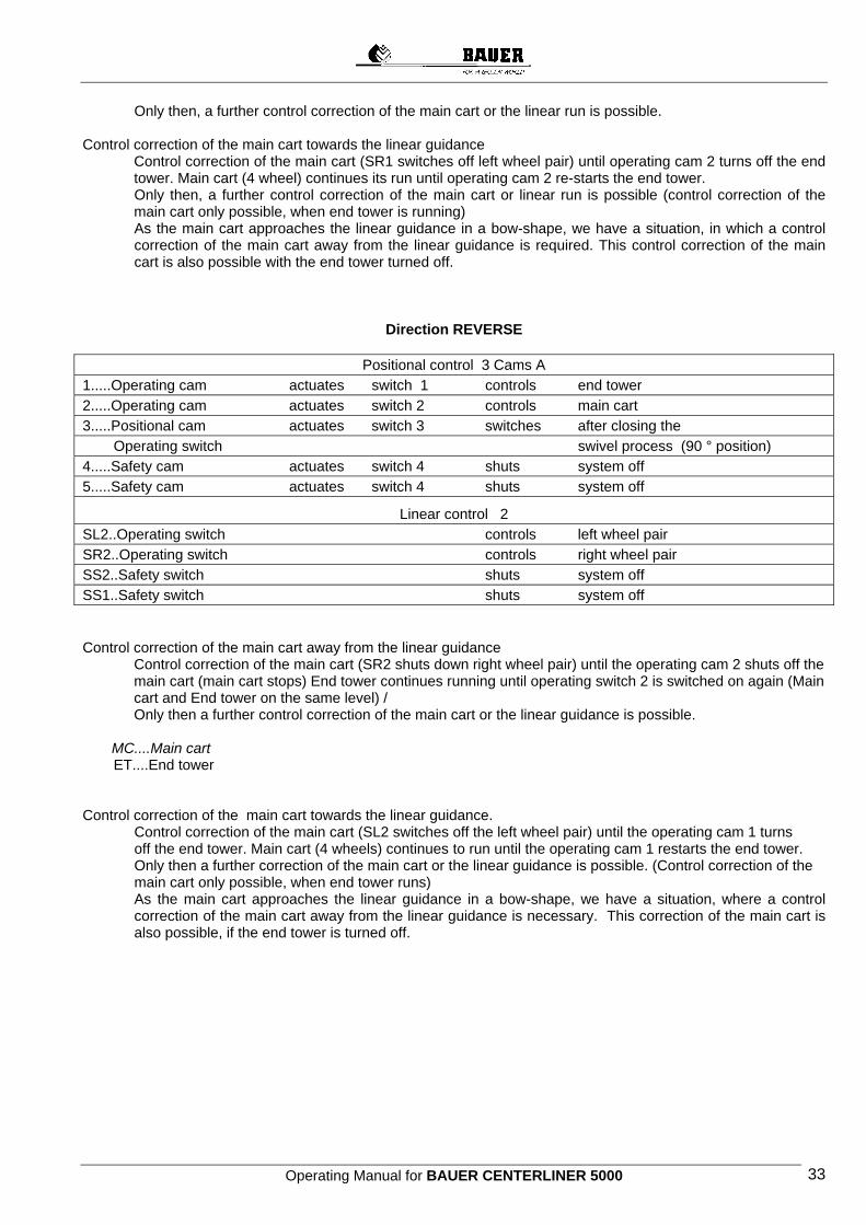
12.1.2 Linear guidance outside of the main cart
Direction FORWARD
Positional control 3 Cams B 1.....Operating cam actuates switch 1 controls main cart 2.....Operating cam actuates switch 2 controls end tower 3.....Position cam actuates switch 3 switches after closing the Operating cam swivel process 4.....Safety cam actuates switch 4 shuts system off 5.....Safety cam actuates switch 4 shuts system off 6.....Position cam actuates switch 6 Linear guidance
Linear control 2 SR2..Operating switch controls right wheel pair SL2..Operating switch controls left wheel pair SS2..Safety switch shuts system off SS1..Safety switch shuts system off
Li G id

Operating Manual for BAUER CENTERLINER 5000 35
Control correction of the main cart towards the linear guidance
Control correction of the main cart (SL2 turns off left wheel pair) until the operating cam 2 switches off the end tower. Main cart (4 wheels) continues to run until the operating cam 2 restarts the end tower. Only then, a further control correction of the main cart or the linear guidance is possible. (control correction of the main cart only possible, when end tower runs) As the main cart approaches the linear guidance in a bow-shape, we have a situation, where a control correction of the main cart away from the linear guidance is necessary. This control correction of the main cart is also possible, when the end tower is turned off.
Control correction of the main cart away from the linear guidance Control correction of the main cart (SR2 turns off the righ wheel pair) until the operating cam 1 shuts off
the main cart (main cart stops). The end tower keeps running until the operating cam 1 switches on again (Main cart and end tower on the same level). Only then, a further correction of the control or the linear guidance is possible.
Direction REVERSE:
Positional control 3 cams B 1.....Operating cam actuates switch 1 controls End tower 2.....Operating cam actuates switch 2 controls Main cart 3.....Position cam actuates switch 3 switches after closing the Operating switch Swivel process 4.....Safety cam actuates switch 4 shuts system off 5.....Safety cam actuates switch 4 shuts system off 6.....Position cam actuates switch 6 linear guidance
Linear control 1 SR1..Switch switches right wheel pair SL1..Switch switches left wheel pair SS1..Safety switch shuts system off SS2..Safety switch shuts system off Control correction of the main cart towards the linear guidance Control correction of the main cart (SR1 shuts down left wheel pair) until the operating cam 1shuts down the end tower Main cart (4 wheels) keeps running until the operating cam 1 restarts the end tower. Only then, a further control correction of the main cart or the linear guidance is possible. (control correction of the main cart only possible, when the end tower runs) As the mai cart approaches the linear guidance in a bow-shape, we have a situation, which requires a control correction of the main cart away from the linear guidance. This control correction of the main cart is also possible, when the end tower is shut down. Control correction of the main cart away from the linear guidance
Control correction of the main cart (SL1 shuts down right wheel pair) until the operating cam 2 shuts off the main cart (main cart stops). End tower keeps running until the operating cam 2 switches on again (main cart and end tower on the same level). Only then a further control correction of the main cart or of the linear guidance is possible.
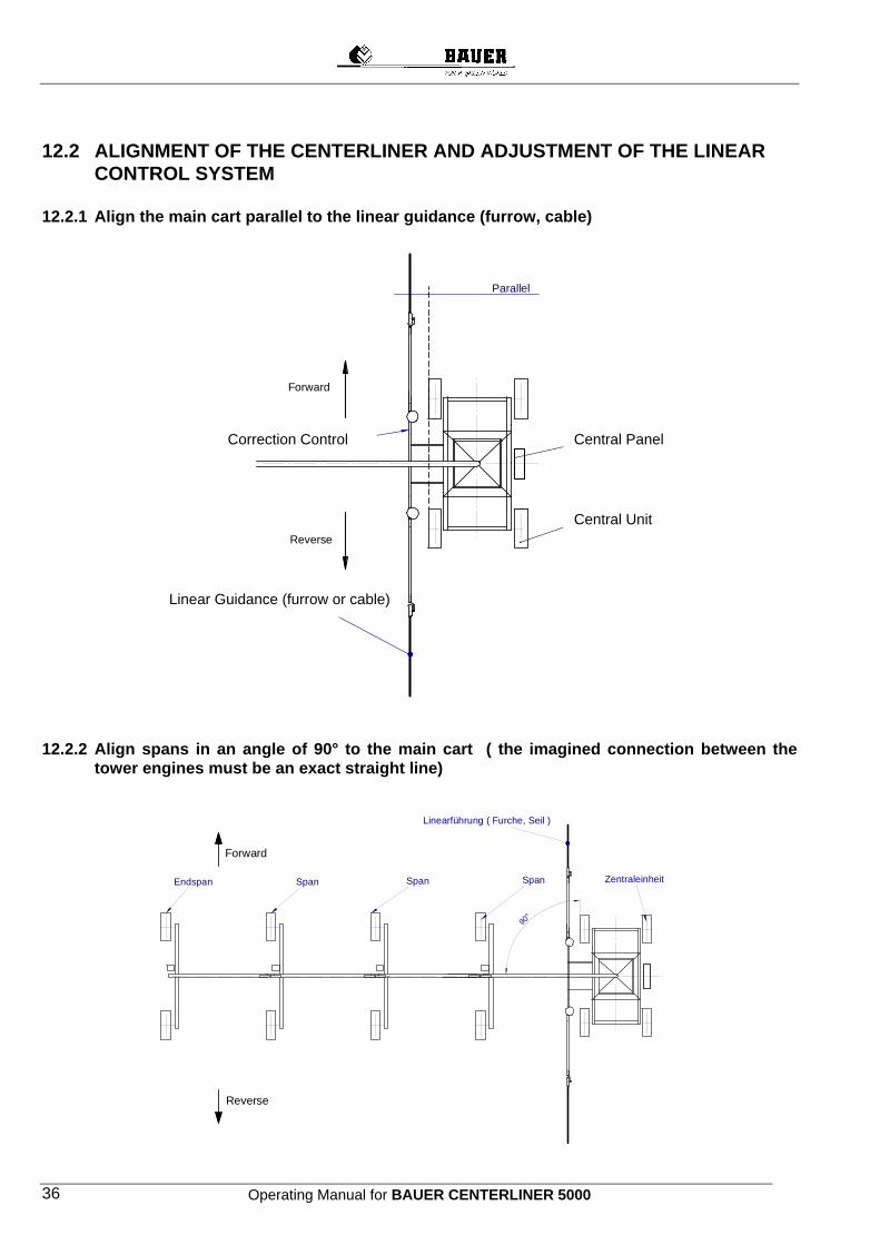
Operating Manual for BAUER CENTERLINER 5000 36
12.2 ALIGNMENT OF THE CENTERLINER AND ADJUSTMENT OF THE LINEAR CONTROL SYSTEM
12.2.1 Align the main cart parallel to the linear guidance (furrow, cable)
12.2.2 Align spans in an angle of 90° to the main cart ( the imagined connection between the tower engines must be an exact straight line)
Linearführung ( Furche oder Seil )
Korrektursteuerung
Zentraleinheit
Schaltschrank
Reverse
Forward
Parallel
Linearführung ( Furche, Seil )
ZentraleinheitSpanSpanSpan
Reverse
Forward
Endspan
90°
Central Panel
Linear Guidance (furrow or cable)
Correction Control
Central Unit
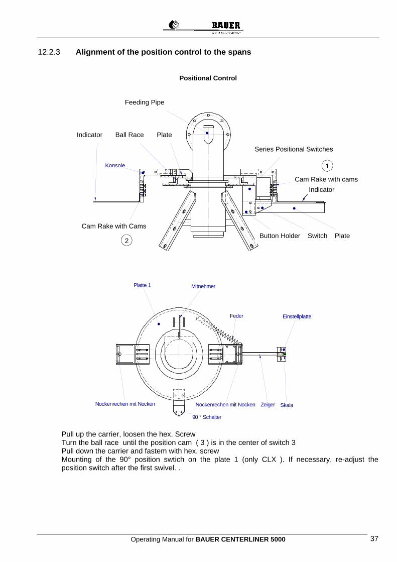
Operating Manual for BAUER CENTERLINER 5000 37
12.2.3 Alignment of the position control to the spans
Positional Control
Pull up the carrier, loosen the hex. Screw Turn the ball race until the position cam ( 3 ) is in the center of switch 3 Pull down the carrier and fastem with hex. screw Mounting of the 90° position swtich on the plate 1 (only CLX ). If necessary, re-adjust the position switch after the first swivel. .
Zeiger
Zeiger
Reihenpositionsschalter
Einspeiserohr 2
Tastenhalter Schalterträger Platte
Kugellenkkranz
Konsole
Nockenrechen mit Nocken
Platte 1
Nockenrechen mit Nocken
1
2
Feder Einstellplatte
SkalaZeiger
MitnehmerPlatte 1
Nockenrechen mit Nocken Nockenrechen mit Nocken
90 ° Schalter
Feeding Pipe
Series Positional Switches
Indicator
Cam Rake with Cams Button Holder Switch Plate
Cam Rake with cams Indicator
Ball Race Plate
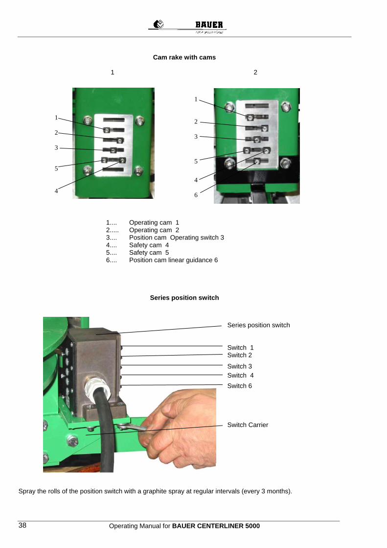
Operating Manual for BAUER CENTERLINER 5000 38
Cam rake with cams
1 2
1.... Operating cam 1 2..... Operating cam 2 3.... Position cam Operating switch 3 4.... Safety cam 4 5.... Safety cam 5 6.... Position cam linear guidance 6
Series position switch
Spray the rolls of the position switch with a graphite spray at regular intervals (every 3 months).
1
2
3
5
4
1
2
3
5
4
6
Series position switch Switch 1 Switch 2
Switch 3
Switch 4
Switch 6
Switch Carrier

Operating Manual for BAUER CENTERLINER 5000 39
Spring
Pointer
Plate
Adjusting plate
Carrier
Ball race
12.3 CHECKING AND RE-ADJUSTMENT OF THE POSITIONAL CONTROL The positional control system has been mounted and set in the workshop. If required, it has to be checked and, if necesary re-adjusted. Proceed as follows:
a) Mount pointer, plate and adjusting plate b) Fasten the spring
c) Turn the ball race until the position cam ( 3 ) is in the center of switch 3
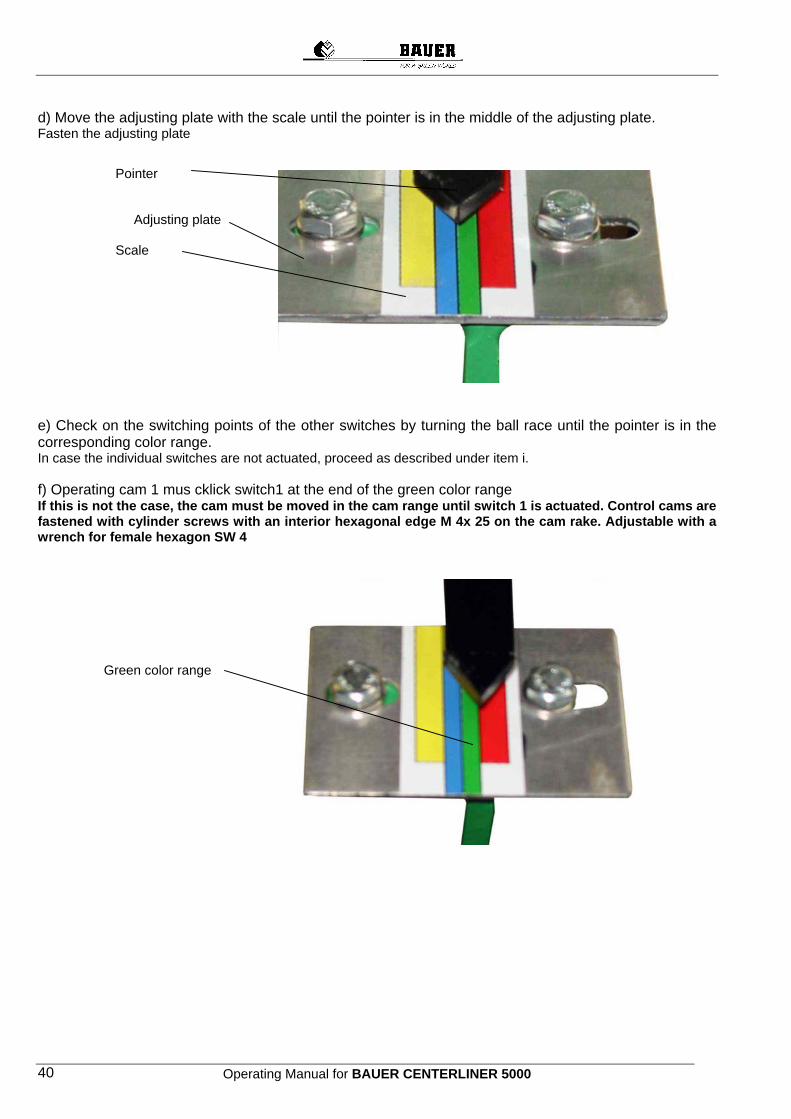
Operating Manual for BAUER CENTERLINER 5000 40
Pointer Adjusting plate Scale
d) Move the adjusting plate with the scale until the pointer is in the middle of the adjusting plate. Fasten the adjusting plate e) Check on the switching points of the other switches by turning the ball race until the pointer is in the corresponding color range. In case the individual switches are not actuated, proceed as described under item i. f) Operating cam 1 mus cklick switch1 at the end of the green color range If this is not the case, the cam must be moved in the cam range until switch 1 is actuated. Control cams are fastened with cylinder screws with an interior hexagonal edge M 4x 25 on the cam rake. Adjustable with a wrench for female hexagon SW 4 Green color range

Operating Manual for BAUER CENTERLINER 5000 41
Adjust cam g) Operating cam 2 must click the switch 2 at the end of the blue color range. Blue color range h) Safety cam 4 must click switch 4 at the end of the white frame of the yellow range.
Yellow color range
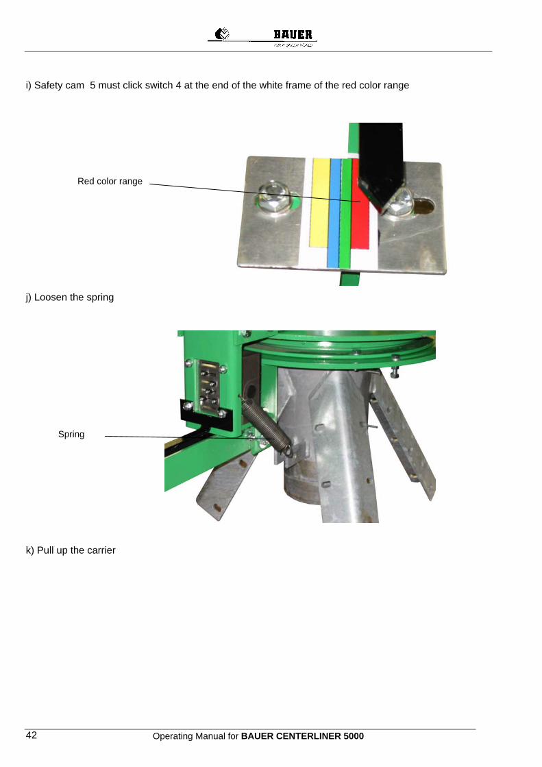
Operating Manual for BAUER CENTERLINER 5000 42
i) Safety cam 5 must click switch 4 at the end of the white frame of the red color range Red color range j) Loosen the spring Spring k) Pull up the carrier
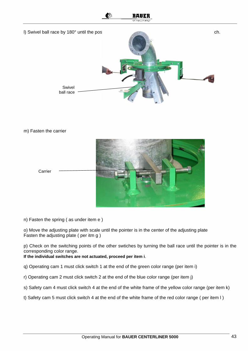
Operating Manual for BAUER CENTERLINER 5000 43
l) Swivel ball race by 180° until the position cam 3 of the cam rake 2 is in the center of the switch.
Swivel ball race m) Fasten the carrier Carrier n) Fasten the spring ( as under item e ) o) Move the adjusting plate with scale until the pointer is in the center of the adjusting plate Fasten the adjusting plate ( per itm g ) p) Check on the switching points of the other swtiches by turning the ball race until the pointer is in the corresponding color range. If the individual switches are not actuated, proceed per item i. q) Operating cam 1 must click switch 1 at the end of the green color range (per item i) r) Operating cam 2 must click switch 2 at the end of the blue color range (per item j) s) Safety cam 4 must click switch 4 at the end of the white frame of the yellow color range (per item k) t) Safety cam 5 must click switch 4 at the end of the white frame of the red color range ( per item l )

Operating Manual for BAUER CENTERLINER 5000 44
u) Position cam linear guidance 6 must click switch 6 in the white color range White range v) ) Loosen the spring ( per item m ) w) Pull up the carrier x) Swivel the ball race by 180° until the position cam 3 of the cam rake 1 is in the centerof the switch. (per item o ) y) Fasten the carrier ( per item p ) z) Demount the pointer, the plate and the adjusting plate.

Operating Manual for BAUER CENTERLINER 5000 45
13 TOWER BOX A tower box is mounted on every tower (between every span). The tower box guarantees the straight run of the CENTERLINERS. Every angular deviation between the individual spans is transmitted via a shift linkage and a control cam to the microswitch, which turn the drive motors on and off and keep the system perfectly aligned. One microswitch is the operating switch, a second one a safety switch, which shuts the system down in case of a too large angular deviation between the spans. In addition to the microswitches an RC-link is mounted, which compensates spikes and protects the control element.
A precise setting of the control element is required for a flawless functioning of the plant. Every alignment control directly delivered from the works is adjusted and tested. Working voltage 400 V, control voltage 220 V/50 Hz.
13.1 MICROSWITCH ADJUSTMENT When a new microswitch (control or safety switch) is mounted in a tower box, set it precisely in the correct working position. Dicsonnect the entire system from power before starting the installation. Set the microswitches as follows: 1. Loosen the switch fixing screw. 2. To set the control switch, rotate the control cam until the switch roller rests in the notch „A“. Adjust the switch in the bolt holes towards the control cam until the control switch (microswitch) actuates (clicks). Therby the bracket of the switch lies near the switch housing. Fix the switch with the screws in this position.
3. To set the safety switch, rotate the control cam until the switch roller rests in notch „B“. Move the switch toward the cam until it actuates (clicks). Thereby the bracket of the switch is near to the switch housing. Fix the switch in this position with the screws. 4. Check the switching points, if necessary, repeat the setting procedure.
Operating Manual for BAUER CENTERLINER 5000 46
14 ELECTRICAL SYSTEM
WARNING !
System is powered by 220 Volts and 400 Volts (460 Volts) ! All installation and service work must be performed with extreme care - only by a qualified person - and in strict compliance with the relevant safety codes !
WARNING !
Complete electrical installation to be carried out ONLY with the system de-energised !
14.1 Cables and markings 1. The pivot cable consists of 11 phases which are marked by colours.
Phase colour Phase number Black 1 Blue 2
Power circuit
Brown 3 Pink 4 Grey 5 Red 6 White 7 Violet 8 Green 9
Control circuit
Orange 10 Grounding conductor yellow/green
2. Cable lengths
The cables are cut to length and stripped at their ends already in the factory. Cable lengths are selected in such a way that the two ends can be pulled into the tower boxes in a slight bend.
3. Mounting the cables On the tower end of the span, where the tower box is mounted on the end pipe, the cable end is laid to the end of the pipe and in this position it is fixed on the pipe with the spring clip. In this position the cable mounting length is correct on both sides.
14.2 Installation and connection of the pivot panel
WARNING !
The electrical supply line must be disconnected from all power for connecting the pivot panel and for all system electrical work !
1. Lay down the collector cable through the cable conduit in the feed pipe. Pull this collector cable into the pivot
panel and connect it to the terminal strip according to the wiring diagram. 2. Connect 3 phases of the feeding cable in the pivot panel according to the connecting diagram. (clockwise
rotating field – check with rotating field tester. In case rotating field is counterclockwise, change 2 phases of the feeding cable on the master switch.
3. Tighten the screwed joints at the panel inlet to prevent entry of moisture.
Operating Manual for BAUER CENTERLINER 5000 47
14.3 Tower box connection 1. The beginning of the pivot cable on the first span is connected to the collector. Numbering of the connections
in the pivot panel, in the collector and in the tower boxes is identical (see wiring diagrams - item 29).
2. Lay 3 cables into the tower box. incoming feeder cable, forwarding of feeder cable, cable to the tower drive motor
3. Connections to be made according to the enclosed wiring diagrams (see wiring diagrams – item 29).
4. Distinguish between different tower box options (see Section 17).
NOTE !
Correct wiring of all tower boxes is essential. If phases are exchanged the towers travel into different directions !
5. Both coupling halves of the spans must be connected to the grounding conductor. 6. Tighten the screwed cable entry into the box to prevent moisture from penetrating into the housing.
15 INITIAL START-UP
15.1 Pivot check-up 1. Are all screwed joints tightened? 2. Is the feed pipe 2 in the pivot head lubricated ? (recommended: Molykote BR 2 plus) 3. Is the stuffing box gland or are the packing bolts not tightened too strongly ? 4. Is the feed pipe 1 flush with feed pipe 2 ? 5. Do the clamps fit tightly to the counter bearing and are they tightly screwed ? 6. Are the pivot panel and the slip ring collector correctly wired ?
Test the conductive continuity by means of the circuit diagrams with a measuring instrument.
15.2 Check-up of trussing and towers 1. Are all screwed joints firmly tightened? (flanged bolts with 100 Nm) 2. Are the ball screws of the wheels firmly tightened? (tightening torque 130 Nm) 3. Is the tyre pressure
1,1 bar with tyres 14,9 - 24 2,1 bar with tyres 11,2 - 24 0,8 bar with tyres 16,9 R 24
4. Are the gearboxes and drive motors filled with oil ? 5. Are the ball joints in the tower couplings lubricated ? (recommended: Molykote BR 2 plus) 6. Are the electric cables fixed properly? 7. Are the cable entries moisture-tight ? 8. Are the sprinklers or spray nozzles installed in the proper position according to the supplied computer chart ?
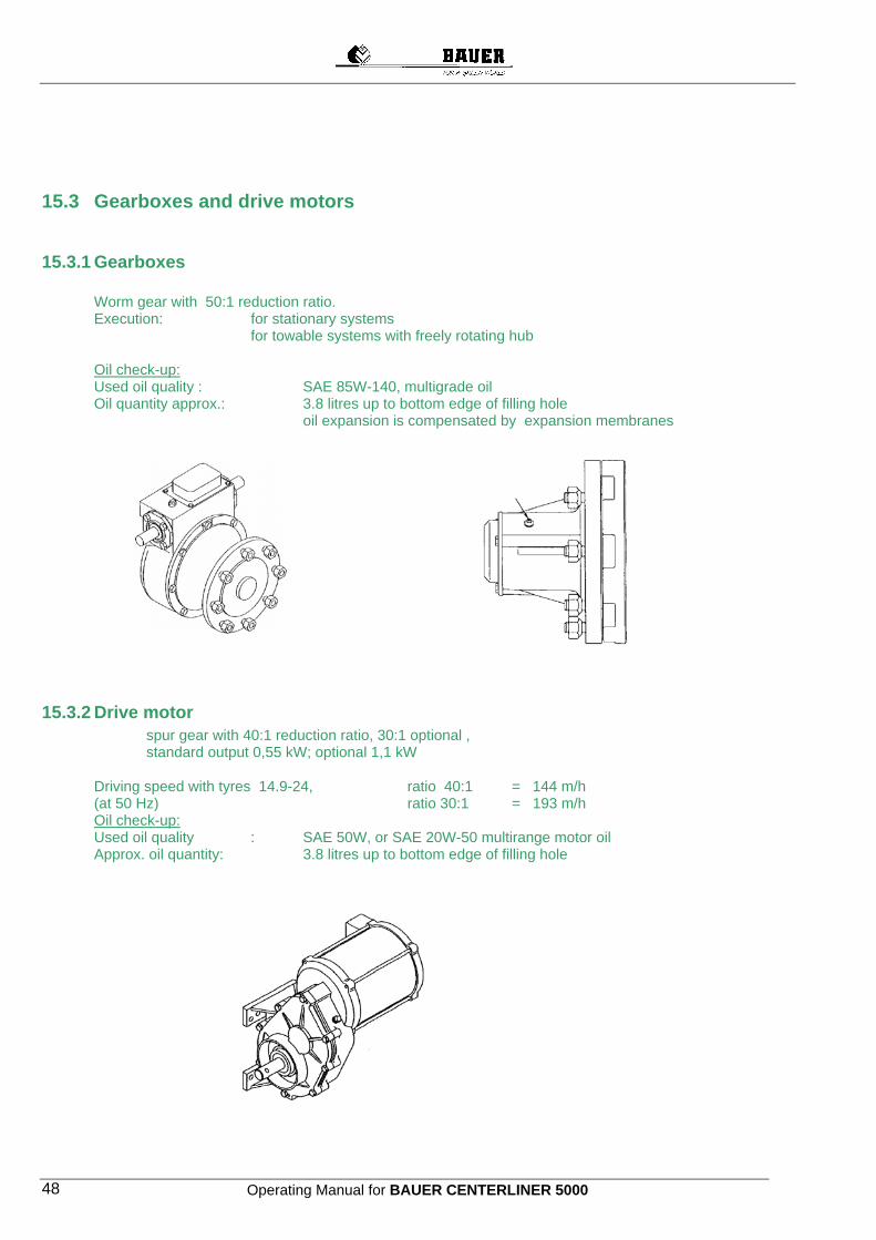
Operating Manual for BAUER CENTERLINER 5000 48
15.3 Gearboxes and drive motors
15.3.1 Gearboxes Worm gear with 50:1 reduction ratio. Execution: for stationary systems for towable systems with freely rotating hub
Oil check-up: Used oil quality : SAE 85W-140, multigrade oil Oil quantity approx.: 3.8 litres up to bottom edge of filling hole
oil expansion is compensated by expansion membranes
15.3.2 Drive motor spur gear with 40:1 reduction ratio, 30:1 optional ,
standard output 0,55 kW; optional 1,1 kW Driving speed with tyres 14.9-24, ratio 40:1 = 144 m/h
(at 50 Hz) ratio 30:1 = 193 m/h Oil check-up: Used oil quality : SAE 50W, or SAE 20W-50 multirange motor oil Approx. oil quantity: 3.8 litres up to bottom edge of filling hole
Operating Manual for BAUER CENTERLINER 5000 49
15.4 Pivot panel
WARNING !
All work on electrical control system to be done only by a qualified electrician ! All metal components of the pivot system must be properly grounded or fitted with an electroconductive connection with a yellow/green protective conductor ! The protective conductor must be connected to a suitable grounding (conforming to local codes).
15.4.1 Check-up of voltage and wiring 1. Check mains voltage by measuring.
3—phase alternating current : 400 V +/− 5% / 50 Hz +/− 2% or alternately 460 V +/− 5% / 60 Hz +/− 2%
2. Check the control voltage on transformer (L11, N11). 230 V +/- 5% 3. Disconnect power supply and disconnect the wires no. 4, 5, and 6 in the pivot panel thus interrupting the
control circuit to the tower boxes. 4. Turn on the power supply by reclosing the main disconnect Q1. 5. Turn the "SAFETY CIRCUIT” switch to OFF position.
WARNING !
In OFF position the "SAFETY CIRCUIT" switch deactivates the safety system !
6. If optional features are mounted, turn them off by means of their respective controls. 7. „CENTERSTAR“ „ON“ 8. Push the green button "FORWARD START" so that the reversing contactor K2 picks up. Towers must not start
to operate. 9. While pushing the "FORWARD START" button check with a measuring instrument if the control voltage of 220
V is applied between the terminals 4 and 6. If not, turn off main disconnect and exchange the lines to the terminals 5 and 6 in the pivot panel
10. Crosscheck in position "REVERSE START" according to diagrams 6 and 7: The control voltage must be applied between the clamps 4 and 5.
11. Turn off power infeed at main disconnect Q1. 12. Reconnect the cores no. 4, 5 and 6 of the pivot cable in the pivot panel.
15.4.2 Check-up of tower travel direction - Turn the "SAFETY CIRCUIT" switch to OFF position .
WARNING !
In OFF position, the “SAFETY CIRCUIT” switch deactivates the safety system !
- start generating set - Turn on power supply at the main disconnect Q1. - Turn „CENTERLINER“ to ON - Hold the “FORWARD START“ button depressed. The system must start in clockwise direction. When pushing the “REVERSE START“ the system must start counter-clockwise. - In case of faulty run the “FORWARD START“ or „REVERSE START must be released immediately ! In case the travel direction of the wheel pairs of the central tower don´t match, change 2 phases of the feeding cable on the main switch Q1 after shut off of electric power supply. - If none of the towers starts correctly into the selected travel direction, two phases of the feeder on the main disconnect Q1 must be exchanged after disconnecting the system from power. - If only individual towers run faulty (travel into the wrong direction), reverse the poles of the motor supply cable at the respective tower – after system has been disconnected from power.
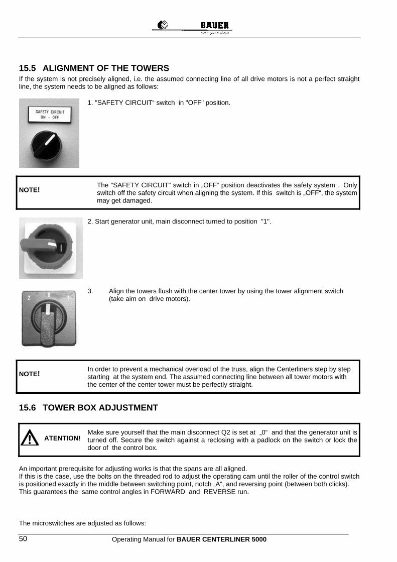
Operating Manual for BAUER CENTERLINER 5000 50
15.5 ALIGNMENT OF THE TOWERS If the system is not precisely aligned, i.e. the assumed connecting line of all drive motors is not a perfect straight line, the system needs to be aligned as follows:
1. "SAFETY CIRCUIT“ switch in "OFF" position.
NOTE! The "SAFETY CIRCUIT" switch in „OFF“ position deactivates the safety system . Only switch off the safety circuit when aligning the system. If this switch is „OFF“, the system may get damaged.
2. Start generator unit, main disconnect turned to position "1".
3. Align the towers flush with the center tower by using the tower alignment switch (take aim on drive motors).
NOTE! In order to prevent a mechanical overload of the truss, align the Centerliners step by step starting at the system end. The assumed connecting line between all tower motors with the center of the center tower must be perfectly straight.
15.6 TOWER BOX ADJUSTMENT Make sure yourself that the main disconnect Q2 is set at „0“ and that the generator unit is
turned off. Secure the switch against a reclosing with a padlock on the switch or lock the door of the control box.
An important prerequisite for adjusting works is that the spans are all aligned. If this is the case, use the bolts on the threaded rod to adjust the operating cam until the roller of the control switch is positioned exactly in the middle between switching point, notch „A“, and reversing point (between both clicks). This guarantees the same control angles in FORWARD and REVERSE run. The microswitches are adjusted as follows:
ATENTION!
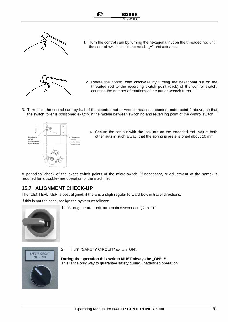
Operating Manual for BAUER CENTERLINER 5000 51
1. Turn the control cam by turning the hexagonal nut on the threaded rod until
the control switch lies in the notch „A“ and actuates.
2. Rotate the control cam clockwise by turning the hexagonal nut on the
threaded rod to the reversing switch point (click) of the control switch, counting the number of rotations of the nut or wrench turns.
3. Turn back the control cam by half of the counted nut or wrench rotations counted under point 2 above, so that
the switch roller is positioned exactly in the middle between switching and reversing point of the control switch.
4. Secure the set nut with the lock nut on the threaded rod. Adjust both
other nuts in such a way, that the spring is pretensioned about 10 mm.
A periodical check of the exact switch points of the micro-switch (if necessary, re-adjustment of the same) is required for a trouble-free operation of the machine.
15.7 ALIGNMENT CHECK-UP The CENTERLINER is best aligned, if there is a sligh regular forward bow in travel directions.
If this is not the case, realign the system as follows:
1. Start generator unit, turn main disconnect Q2 to "1".
2. Turn "SAFETY CIRCUIT" switch "ON". During the operation this switch MUST always be „ON“ !! This is the only way to guarantee safety during unattended operation.
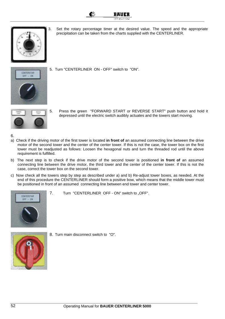
Operating Manual for BAUER CENTERLINER 5000 52
3. Set the rotary percentage timer at the desired value. The speed and the appropriate precipitation can be taken from the charts supplied with the CENTERLINER.
5. Turn "CENTERLINER ON - OFF" switch to "ON".
5. Press the green "FORWARD START or REVERSE START" push button and hold it depressed until the electric switch audibly actuates and the towers start moving.
6. a) Check if the driving motor of the first tower is located in front of an assumed connecting line between the drive
motor of the second tower and the center of the center tower. If this is not the case, the tower box on the first tower must be readjusted as follows: Loosen the hexagonal nuts and turn the threaded rod until the above requirement is fulfilled.
b) The next step is to check if the drive motor of the second tower is positioned in front of an assumed connecting line between the drive motor, the third tower and the center of the center tower. If this is not the case, correct the tower box on the second tower.
c) Now check all the towers step by step as described under a) and b) Re-adjust tower boxes, as needed. At the end of this procedure the CENTERLINER should form a positive bow, which means that the middle tower must be positioned in front of an assumed connecting line between end tower and center tower.
7. Turn "CENTERLINER OFF - ON" switch to „OFF".
8. Turn main disconnect switch to "O".

Operating Manual for BAUER CENTERLINER 5000 53
16 TERMINOLOGY Forward Looking from the main cart in the direction of the system, the CENTERLINER runs to the right or when swivelling the plant the CENTERLINER runs clockwise.
Reverse Looking from the main cart in the direction of the system, the CENTERLINER runs to the left or when swivelling the system the CENTERLINER runs anti-clockwise.
Inward Direction main cart
Outward Direction last tower
Positive bow hurrying ahead If the middle towers are in front of an assumed, straight line in travel direction between main cart and end tower.
Negativer bow hurrying backward If the middle towers are behind an assumed, straight line in travel direction between main cart and end tower.
Dogleg Happens, when a tower gets slower or stands still resp. hurries on ahead of the other towers.
17 START-UP CLS The CENTELINER is only to be released for operation to the customer after it has been completely assembled and installed and after a successful start-up is completed by a qualified person ! As the plant is operated with voltages of 400 V or 460 V, the control components and the electric drive need to be handled with the utmost caution ! Service and repair works should only be done by a professional electrician ! Before starting the system check, if all hooked up generator units (generators) are ready for operation. Have the responsible service center repair possible damages, before you start irrigating. Be extremely cautious with live parts. The starting as described below is valid for a BAUER CENTERLINER without options. In case the system has various options (see chapter options), these should be set or switched on before the start-up .
17.1 STARTING PROCEDURE WITH CONTROL PANEL STANDARD 17.1.1 Start • Connect the supply hose to hydrant and main cart, open water supply. • Turn the disconnect GENERATOR STOP to OFF • Start the generator unit • Turn MAIN DISCONNECT to ON. • Set the desired speed with the percentage setting. • Turn the SAFETY CIRCUIT to ON • Turn LINEAR – SWIVEL switch to LINEAR or SWIVEL. • Turn switch WET – DRY to WET. • Turn CENTERLINER switch to ON. • As desired, press START FORWARD oder START REVERSE.
The CENTERLINER starts operating. If the switch ENDSTOP or INTERMEDIATE STOP is actuated, keep the start button pressed until the main cart has moved out of the operating range.
• If you have option INTERMEDIATE STOP, turn INTERMEDIATE STOP to ON. • Turn generator unit stop to ON
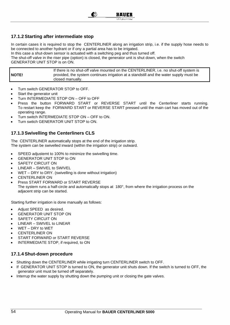
Operating Manual for BAUER CENTERLINER 5000 54
17.1.2 Starting after intermediate stop In certain cases it is required to stop the CENTERLINER along an irrigation strip, i.e. if the supply hose needs to be connected to another hydrant or if ony a partial area has to be irrigated. In this case a shut-down sensor is actuated with a switching peg and thus turned off. The shut-off valve in the riser pipe (option) is closed, the generator unit is shut down, when the switch GENERATOR UNIT STOP is on ON.
NOTE!
If there is no shut-off valve mounted on the CENTERLINER, i.e. no shut-off system is provided, the system continues irrigation at a standstill and the water supply must be closed manually.
• Turn switch GENERATOR STOP to OFF. • Start the generator unit • Turn INTERMEDIATE STOP ON – OFF to OFF • Press the button FORWARD START or REVERSE START until the Centerliner starts running.
To restart keep the FORWARD START or REVERSE START pressed until the main cart has moved out of the operating range.
• Turn switch INTERMEDIATE STOP ON – OFF to ON. • Turn swtich GENERATOR UNIT STOP to ON.
17.1.3 Swivelling the Centerliners CLS The CENTERLINER automatically stops at the end of the irrigation strip. The system can be swivelled inward (within the irrigation strip) or outward. • SPEED adjustemt to 100% to minimize the swivelling time. • GENERATOR UNIT STOP to ON • SAFETY CIRCUIT ON • LINEAR – SWIVEL to SWIVEL • WET – DRY to DRY. (swivelling is done without irrigation) • CENTERLINER ON • Press START FORWARD or START REVERSE
The system runs a half-circle and automatically stops at 180°, from where the irrigation process on the adjacent strip can be started.
Starting further irrigation is done manually as follows:
• Adjust SPEED as desired. • GENERATOR UNIT STOP ON • SAFETY CIRCUIT ON • LINEAR – SWIVEL to LINEAR • WET – DRY to WET • CENTERLINER ON • START FORWARD or START REVERSE • INTERMEDIATE STOP, if required, to ON
17.1.4 Shut-down procedure • Shutting down the CENTERLINER while irrigating turn CENTERLINER switch to OFF. • If GENERATOR UNIT STOP is turned to ON, the generator unit shuts down. If the switch is turned to OFF, the
generator unit must be turned off separately. • Interrup the water supply by shutting down the pumping unit or closing the gate valves.
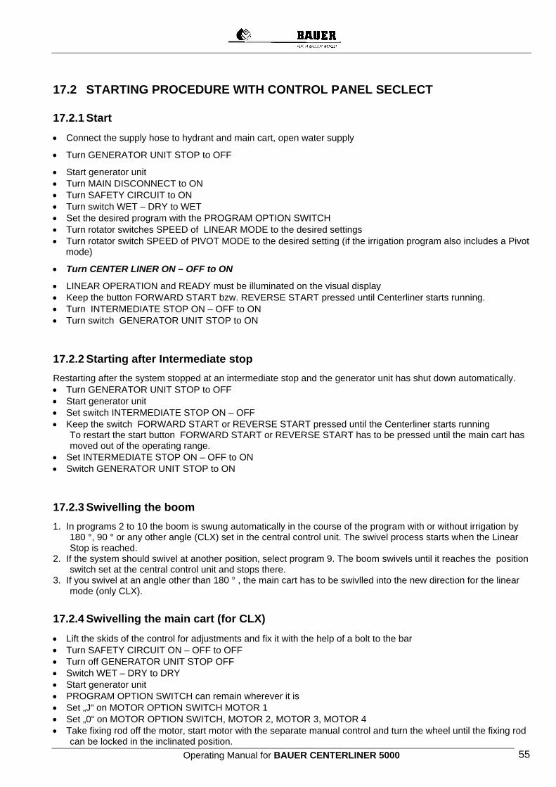
Operating Manual for BAUER CENTERLINER 5000 55
17.2 STARTING PROCEDURE WITH CONTROL PANEL SECLECT
17.2.1 Start • Connect the supply hose to hydrant and main cart, open water supply
• Turn GENERATOR UNIT STOP to OFF
• Start generator unit • Turn MAIN DISCONNECT to ON • Turn SAFETY CIRCUIT to ON • Turn switch WET – DRY to WET • Set the desired program with the PROGRAM OPTION SWITCH • Turn rotator switches SPEED of LINEAR MODE to the desired settings • Turn rotator switch SPEED of PIVOT MODE to the desired setting (if the irrigation program also includes a Pivot mode)
• Turn CENTER LINER ON – OFF to ON
• LINEAR OPERATION and READY must be illuminated on the visual display • Keep the button FORWARD START bzw. REVERSE START pressed until Centerliner starts running. • Turn INTERMEDIATE STOP ON – OFF to ON • Turn switch GENERATOR UNIT STOP to ON
17.2.2 Starting after Intermediate stop Restarting after the system stopped at an intermediate stop and the generator unit has shut down automatically. • Turn GENERATOR UNIT STOP to OFF • Start generator unit • Set switch INTERMEDIATE STOP ON – OFF • Keep the switch FORWARD START or REVERSE START pressed until the Centerliner starts running
To restart the start button FORWARD START or REVERSE START has to be pressed until the main cart has moved out of the operating range.
• Set INTERMEDIATE STOP ON – OFF to ON • Switch GENERATOR UNIT STOP to ON
17.2.3 Swivelling the boom 1. In programs 2 to 10 the boom is swung automatically in the course of the program with or without irrigation by
180 °, 90 ° or any other angle (CLX) set in the central control unit. The swivel process starts when the Linear Stop is reached.
2. If the system should swivel at another position, select program 9. The boom swivels until it reaches the position switch set at the central control unit and stops there.
3. If you swivel at an angle other than 180 ° , the main cart has to be swivlled into the new direction for the linear mode (only CLX).
17.2.4 Swivelling the main cart (for CLX) • Lift the skids of the control for adjustments and fix it with the help of a bolt to the bar • Turn SAFETY CIRCUIT ON – OFF to OFF • Turn off GENERATOR UNIT STOP OFF • Switch WET – DRY to DRY • Start generator unit • PROGRAM OPTION SWITCH can remain wherever it is • Set „J“ on MOTOR OPTION SWITCH MOTOR 1 • Set „0“ on MOTOR OPTION SWITCH, MOTOR 2, MOTOR 3, MOTOR 4 • Take fixing rod off the motor, start motor with the separate manual control and turn the wheel until the fixing rod
can be locked in the inclinated position.

Operating Manual for BAUER CENTERLINER 5000 56
• Turn MOTOR OPTION SWITCH MOTOR 1 to „0“ • Set „J“ on MOTOR OPTION SWITCH MOTOR 2 (MOTOR 3, MOTOR 4 remain at „0“) • Repeat the swivel procedure until all wheels are swivelled. • Set „J“ on all MOTOR OPTION SWITCHES • Start main cart with the separate manual control forward or reverse • Main cart remains in 90 ° position to boom also with manual control turned on. If the subsequent operating
position is at the 90 ° position, the motors are turned off with the manual position. If the subsequent operating position is at another position, the manual control remains turned on and the system continues running after a few seconds, until the manual control is turned off.
• The system is again ready for linear operation, when the visual indication LINEAR OPERATION is illuminated, i.e. when the main cart is at 90 ° to the boom.
• Leave MOTOR OPTION SWITCH MOTOR 1 at „l“ • Set MOTOR OPTION SWITCH, MOTOR 2, MOTOR 3, MOTOR 4 to „0“ • Take fixing rod of motor, start motor with separate manual control and turn the wheel until fixing rod can be
locked in straight position again. • Set MOTOR OPTION SWITCH MOTOR 1 to „0“ • Set MOTOR OPTION SWITCH MOTOR 2 to „l“ (MOTOR 3, MOTOR 4 remain at „0“) • Repeat the swivel procedure until all wheels are swivelled. • Set all MOTOR OPTION SWITCHES to „l“. • Turn SAFETY CIRCUIT to ON • Turn GENERATOR UNIT STOP to ON • Turn switch WET – DRY to WET • Loose the bolt for fixing the skids and bring down the skids • Further starting procedure as described under START
17.2.5 Shut-down procedure Shut down the Centerliner during irrigation • Turn switch CENTERLINER ON – OFF to OFF • If the GENERATOR UNIT STOP switch is turned to ON, the generator unit shuts down automatically. If the
switch is turned to OFF, the generator unit must be turned off separately. • Water supply will be interrupted automatically, if shut-off valve is mounted.
17.3 ALIGNMENT OF THE SYSTEM
The system is only ready for the linear mode, if both „Linear mode“ (7) and „Ready“ (8) are illuminated.
17.3.1 Alignment of the main cart 1. If the main cart is not parallel to the control furrows or the control cable, the main cart must be aligned or put
parallel to the control furrow or control cable. 2. If the linear control or the central control is in the safety circuit, the safety circuit has to be interrupted. (Switch
12) OFF 3. Determine, if the operating range of the linear control is positioned correctly, i.e. the control arms in the
operating range are aligned with the frames of the main cart. If that is not the case, the micro switches have to be re-positioned. Setting as per instructions.
4. Get the boom at 90° to the main cart with program 9. 5. In programm 1 (linear) run system with main cart forward or reverse. Main cart gets more and more aligned
parallel to the control furrow or control cable.
NOTE: Take care that, while aligning, the angle between the main cart and the boom remains close to 90 ° . If the main cart gets too far off, the boom has to be re-set with programm 9. That way, a tension in the system is avoided.
17.3.2 Alignment of the boom for the Linear mode Swivel the boom per item 3.3. until boom is at 90 ° to the main cart and „Linear Mode“ (8) shows up on the illuminated display.
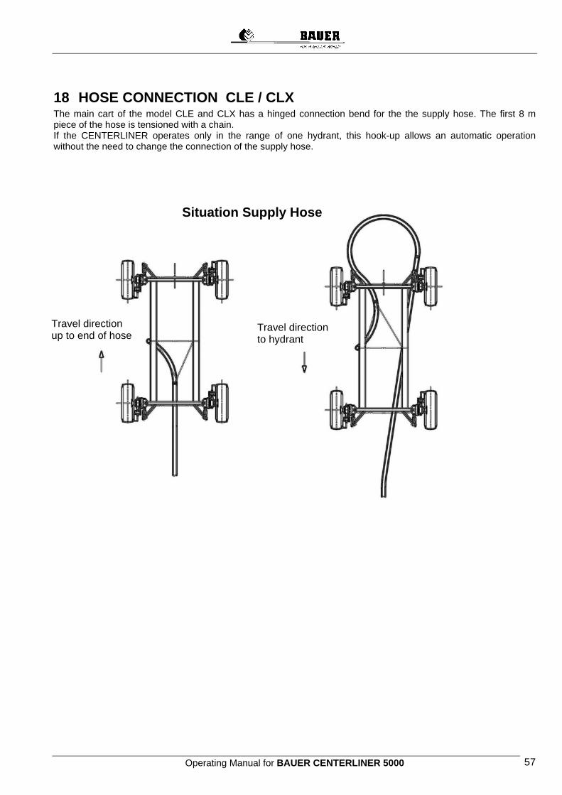
Operating Manual for BAUER CENTERLINER 5000 57
18 HOSE CONNECTION CLE / CLX The main cart of the model CLE and CLX has a hinged connection bend for the the supply hose. The first 8 m piece of the hose is tensioned with a chain. If the CENTERLINER operates only in the range of one hydrant, this hook-up allows an automatic operation without the need to change the connection of the supply hose.
Situation Supply Hose
Travel direction up to end of hose
Travel direction to hydrant
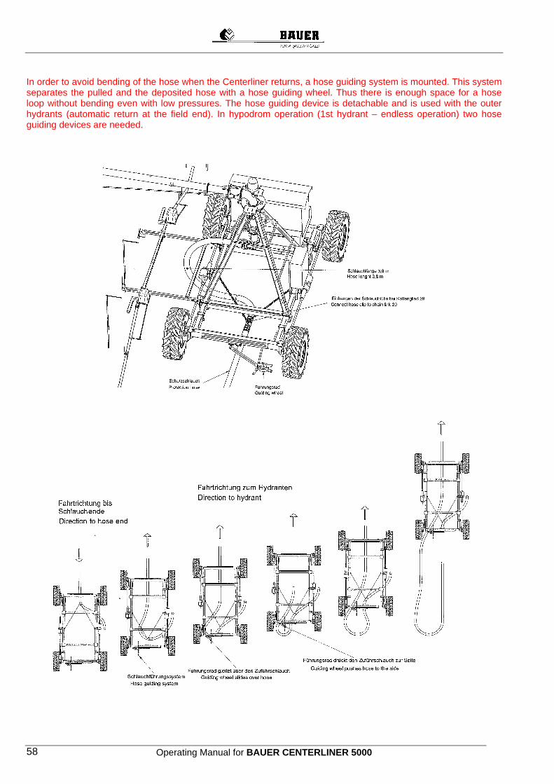
Operating Manual for BAUER CENTERLINER 5000 58
In order to avoid bending of the hose when the Centerliner returns, a hose guiding system is mounted. This system separates the pulled and the deposited hose with a hose guiding wheel. Thus there is enough space for a hose loop without bending even with low pressures. The hose guiding device is detachable and is used with the outer hydrants (automatic return at the field end). In hypodrom operation (1st hydrant – endless operation) two hose guiding devices are needed.
Operating Manual for BAUER CENTERLINER 5000 59
19 MAINTENANCE INSTRUCTIONS Notice Warranty claims will only be accepted if rules of handling and maintenance (according to service plan) has been followed. Service should be done by an authorised dealer and confirmed in the service plan. The service plan is considered as evidence for warranties. The meaning of service plan The service plan suggests when to do a service and what kind of service should be done. In the fields that provides evidence we confirm the carrying out of the service. This services can be a condition for possible warranty claims. We kindly ask you to understand that wasting and damages due to inroad, improper handling or changes are not included in the warranty. Always disconnect the system from all power before starting any maintenance work. Turn the main disconnect to “0“ and activate the safety lock-out to prevent unauthorised or unintentional re-closing of the system. Always disconnect the system yourself - do not depend on other persons. Always re-mount all protective devices dismantled during maintenance.
19.1 Service-ranges Monthly service Annual service
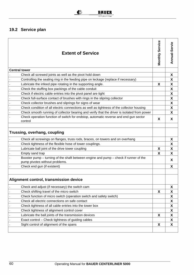
Operating Manual for BAUER CENTERLINER 5000 60
19.2 Service plan
Extent of Service
Mon
thly
Ser
vice
Ann
ual-S
ervi
e
Central tower - Check all screwed joints as well as the pivot hold down X - Controlling the sealing ring in the feeding pipe on leckage (replace if necessary) X - Lubricate the infeed pipe rotating in the supporting angle. X X - Check the stuffing box packings of the cable conduit X - Check if electric cable entries into the pivot panel are tight X - Check full-surface contact of brushes with rings in the slipring collector X - Check collector brushes and sliprings for signs of wear X - Check condition of all electric connections as well as tightness of the collector housing X - Check smooth running of collector bearing and verify that the driver is isolated from power X - Check operation function of switch for endstop, automatic reverse and end gun sector control X X
Trussing, overhang, coupling
- Check all screwings on flanges, truss rods, braces, on towers and on overhang X - Check tightness of the flexible hose of tower couplings. X - Lubricate ball joint of the drive tower coupling X X - Empty sand trap X X - Booster pump – turning of the shaft between engine and pump – check if runner of the pump pivotes without problems. X
- Check end gun (if existent) X
Alignment control, transmission device
- Check and adjust (if necessary) the switch cam X - Check shifting travel of the micro switch X X - Check function of micro switch (operation switch and safety switch) X - Check all electric connections on safe contact X - Check tightness of all cable entries into the tower box X - Check tightness of alignment control cover X - Lubricate the ball joints of the transmission devices X X - Exact control – Check tightness of guiding cables X - Sight control of alignment of the spans X X
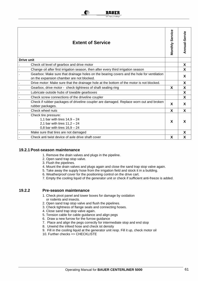
Operating Manual for BAUER CENTERLINER 5000 61
Extent of Service
Mon
thly
Ser
vice
Ann
ual-S
ervi
e
Drive unit - Check oil level of gearbox and drive motor X - Change oil after first irrigation season, then after every third irrigation season X - Gearbox: Make sure that drainage holes on the bearing covers and the hole for ventilation on the expansion chamber are not blocked. X
- Drive motor: Make sure that the drainage hole at the bottom of the motor is not blocked. X - Gearbox, drive motor - check tightness of shaft sealing ring X X - Lubricate outside hubs of towable gearboxes X - Check screw connections of the driveline coupler X - Check if rubber packages of driveline coupler are damaged. Replace worn out and broken rubber packages. X X
- Check wheel nuts X X - Check tire pressure: 1,1 bar with tires 14,9 – 24 2,1 bar with tires 11,2 – 24 0,8 bar with tires 16,9 – 24
X X
- Make sure that tires are not damaged X - Check anti twist device of axle drive shaft cover X X
19.2.1 Post-season maintenance 1. Remove the drain valves and plugs in the pipeline. 2. Open sand trap stop valve. 3. Flush the pipelines. 4. Mount the drain valves and plugs again and close the sand trap stop valve again. 5. Take away the supply hose from the irrigation field and stock it in a building. 6. Weatherproof cover for the positioning control on the drive cart. 7. Empty the cooling liquid of the generator unit or check if sufficient anti-freeze is added.
19.2.2 Pre-season maintenance 1. Check pivot panel and tower boxes for damage by oxidation or rodents and insects. 2. Open sand trap stop valve and flush the pipelines. 3. Check tightness of flange seals and connecting hoses. 4. Close sand trap stop valve again.
5. Tension cable for cable guidance and align pegs 6. Draw a new furrow for the furrow guidance 7. Place and align the pegs correctly for intermediate stop and end stop 8. Unwind the infeed hose and check ist density 9. Fill in the cooling liquid at the generator unit resp. Fill it up, check motor oil 10. Further checks => CHECKLISTE
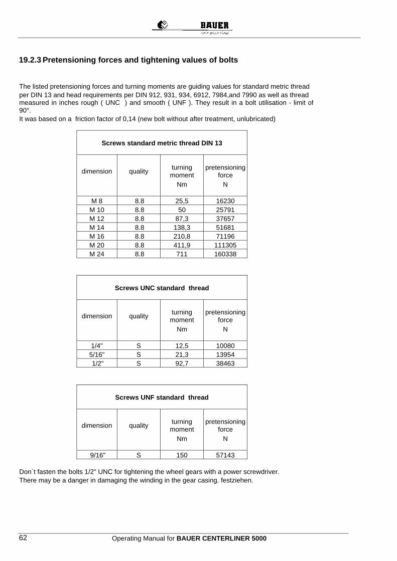
Operating Manual for BAUER CENTERLINER 5000 62
19.2.3 Pretensioning forces and tightening values of bolts The listed pretensioning forces and turning moments are guiding values for standard metric thread per DIN 13 and head requirements per DIN 912, 931, 934, 6912, 7984,and 7990 as well as thread measured in inches rough ( UNC ) and smooth ( UNF ). They result in a bolt utilisation - limit of 90°. It was based on a friction factor of 0,14 (new bolt without after treatment, unlubricated) Screws standard metric thread DIN 13
dimension quality turning
moment pretensioning
force Nm N
M 8 8.8 25,5 16230 M 10 8.8 50 25791 M 12 8.8 87,3 37657 M 14 8.8 138,3 51681 M 16 8.8 210,8 71196 M 20 8.8 411,9 111305 M 24 8.8 711 160338
Screws UNC standard thread
dimension quality turning
moment pretensioning
force Nm N 1/4" S 12,5 10080 5/16" S 21,3 13954 1/2" S 92,7 38463
Screws UNF standard thread
dimension quality turning
moment pretensioning
force Nm N 9/16" S 150 57143
Don´t fasten the bolts 1/2" UNC for tightening the wheel gears with a power screwdriver. There may be a danger in damaging the winding in the gear casing. festziehen.
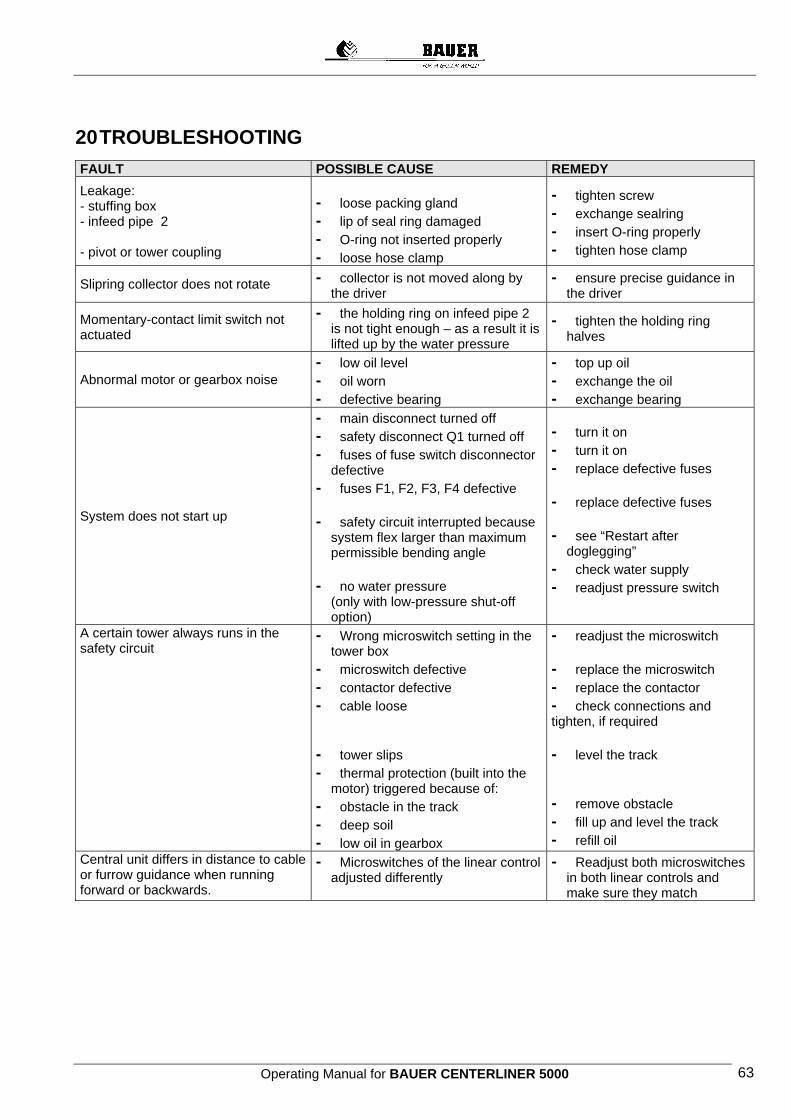
Operating Manual for BAUER CENTERLINER 5000 63
20 TROUBLESHOOTING
FAULT POSSIBLE CAUSE REMEDY Leakage: - stuffing box - infeed pipe 2 - pivot or tower coupling
- loose packing gland - lip of seal ring damaged - O-ring not inserted properly - loose hose clamp
- tighten screw - exchange sealring - insert O-ring properly - tighten hose clamp
Slipring collector does not rotate - collector is not moved along by the driver
- ensure precise guidance in the driver
Momentary-contact limit switch not actuated
- the holding ring on infeed pipe 2 is not tight enough – as a result it is lifted up by the water pressure
- tighten the holding ring halves
Abnormal motor or gearbox noise - low oil level - oil worn - defective bearing
- top up oil - exchange the oil - exchange bearing
System does not start up
- main disconnect turned off - safety disconnect Q1 turned off - fuses of fuse switch disconnector
defective - fuses F1, F2, F3, F4 defective
- safety circuit interrupted because
system flex larger than maximum permissible bending angle
- no water pressure (only with low-pressure shut-off option)
- turn it on - turn it on - replace defective fuses
- replace defective fuses
- see “Restart after
doglegging” - check water supply - readjust pressure switch
A certain tower always runs in the safety circuit
- Wrong microswitch setting in the tower box
- microswitch defective - contactor defective - cable loose - tower slips - thermal protection (built into the
motor) triggered because of: - obstacle in the track - deep soil - low oil in gearbox
- readjust the microswitch - replace the microswitch - replace the contactor - check connections and tighten, if required - level the track - remove obstacle - fill up and level the track - refill oil
Central unit differs in distance to cable or furrow guidance when running forward or backwards.
- Microswitches of the linear control adjusted differently
- Readjust both microswitches in both linear controls and make sure they match
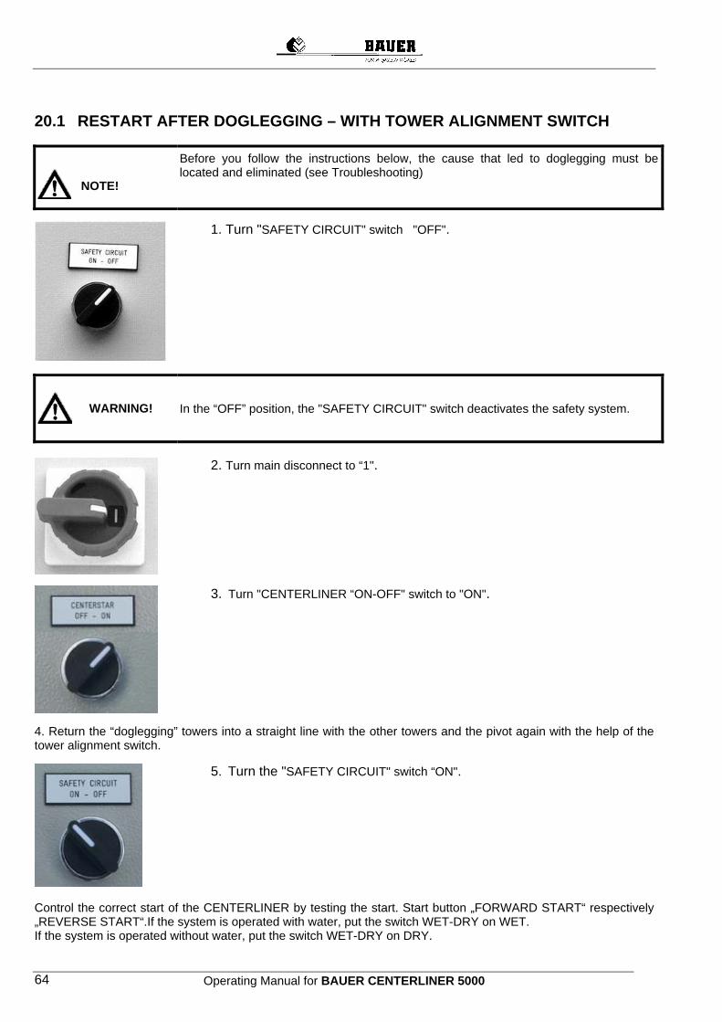
Operating Manual for BAUER CENTERLINER 5000 64
20.1 RESTART AFTER DOGLEGGING – WITH TOWER ALIGNMENT SWITCH Before you follow the instructions below, the cause that led to doglegging must be
located and eliminated (see Troubleshooting)
1. Turn "SAFETY CIRCUIT" switch "OFF".
In the “OFF” position, the "SAFETY CIRCUIT" switch deactivates the safety system.
2. Turn main disconnect to “1".
3. Turn "CENTERLINER “ON-OFF" switch to "ON".
4. Return the “doglegging” towers into a straight line with the other towers and the pivot again with the help of the tower alignment switch.
5. Turn the "SAFETY CIRCUIT" switch “ON".
Control the correct start of the CENTERLINER by testing the start. Start button „FORWARD START“ respectively „REVERSE START“.If the system is operated with water, put the switch WET-DRY on WET. If the system is operated without water, put the switch WET-DRY on DRY.
WARNING!
NOTE!
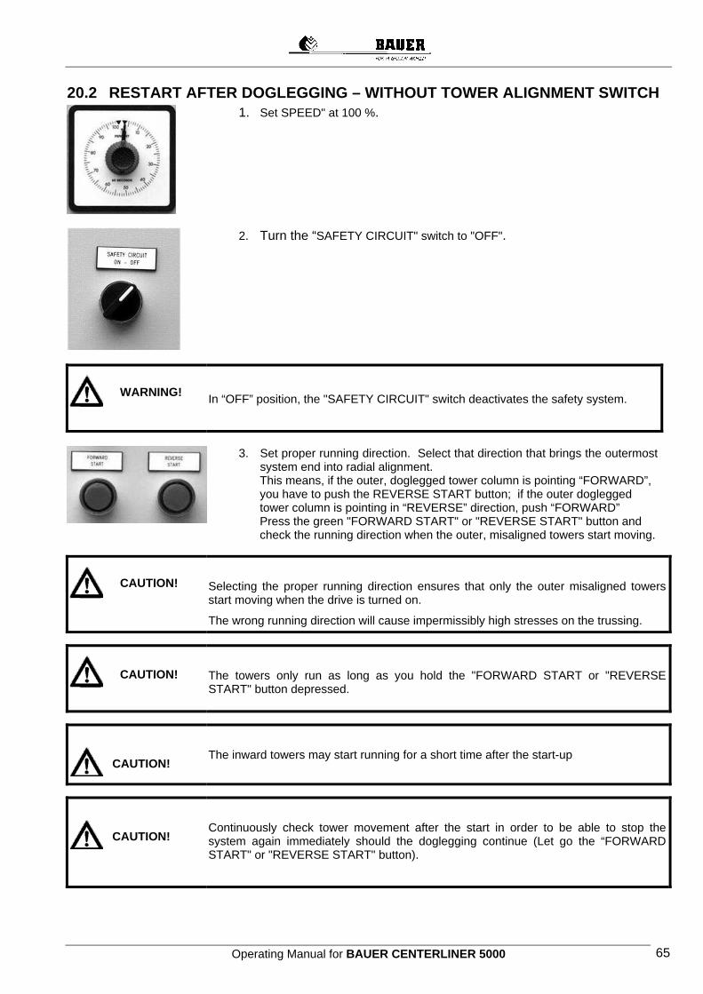
Operating Manual for BAUER CENTERLINER 5000 65
20.2 RESTART AFTER DOGLEGGING – WITHOUT TOWER ALIGNMENT SWITCH
1. Set SPEED" at 100 %.
2. Turn the “SAFETY CIRCUIT" switch to "OFF".
In “OFF” position, the "SAFETY CIRCUIT" switch deactivates the safety system.
3. Set proper running direction. Select that direction that brings the outermost system end into radial alignment.
This means, if the outer, doglegged tower column is pointing “FORWARD”, you have to push the REVERSE START button; if the outer doglegged tower column is pointing in “REVERSE” direction, push “FORWARD” Press the green "FORWARD START" or "REVERSE START" button and check the running direction when the outer, misaligned towers start moving.
Selecting the proper running direction ensures that only the outer misaligned towers start moving when the drive is turned on.
The wrong running direction will cause impermissibly high stresses on the trussing.
The towers only run as long as you hold the "FORWARD START or "REVERSE START" button depressed.
The inward towers may start running for a short time after the start-up
Continuously check tower movement after the start in order to be able to stop the system again immediately should the doglegging continue (Let go the “FORWARD START" or "REVERSE START" button).
WARNING!
CAUTION!
CAUTION!
CAUTION!
CAUTION!
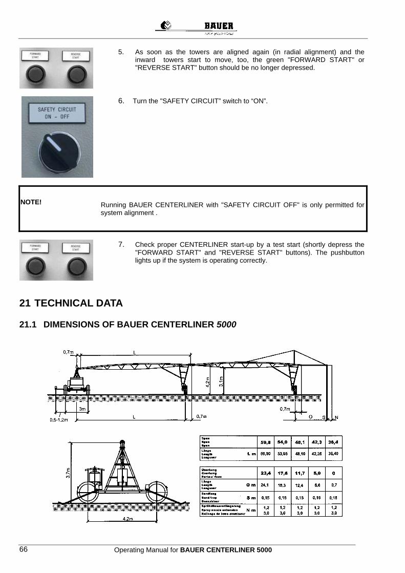
Operating Manual for BAUER CENTERLINER 5000 66
5. As soon as the towers are aligned again (in radial alignment) and the inward towers start to move, too, the green "FORWARD START" or "REVERSE START" button should be no longer depressed.
6. Turn the "SAFETY CIRCUIT” switch to “ON”.
Running BAUER CENTERLINER with "SAFETY CIRCUIT OFF" is only permitted for system alignment .
7. Check proper CENTERLINER start-up by a test start (shortly depress the "FORWARD START" and "REVERSE START" buttons). The pushbutton lights up if the system is operating correctly.
21 TECHNICAL DATA
21.1 DIMENSIONS OF BAUER CENTERLINER 5000
NOTE!
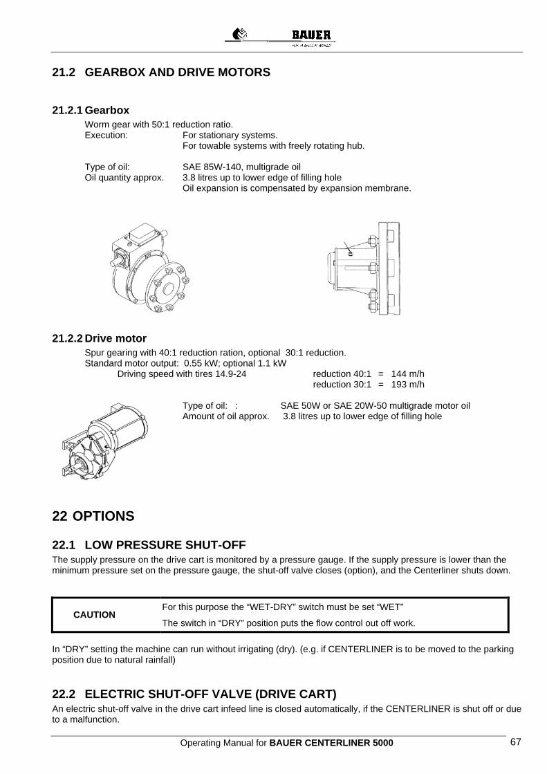
Operating Manual for BAUER CENTERLINER 5000 67
21.2 GEARBOX AND DRIVE MOTORS
21.2.1 Gearbox Worm gear with 50:1 reduction ratio. Execution: For stationary systems. For towable systems with freely rotating hub.
Type of oil: SAE 85W-140, multigrade oil Oil quantity approx. 3.8 litres up to lower edge of filling hole
Oil expansion is compensated by expansion membrane.
21.2.2 Drive motor Spur gearing with 40:1 reduction ration, optional 30:1 reduction.
Standard motor output: 0.55 kW; optional 1.1 kW Driving speed with tires 14.9-24 reduction 40:1 = 144 m/h
reduction 30:1 = 193 m/h
Type of oil: : SAE 50W or SAE 20W-50 multigrade motor oil Amount of oil approx. 3.8 litres up to lower edge of filling hole
22 OPTIONS
22.1 LOW PRESSURE SHUT-OFF The supply pressure on the drive cart is monitored by a pressure gauge. If the supply pressure is lower than the minimum pressure set on the pressure gauge, the shut-off valve closes (option), and the Centerliner shuts down. For this purpose the “WET-DRY” switch must be set “WET”
The switch in “DRY” position puts the flow control out off work.
In “DRY” setting the machine can run without irrigating (dry). (e.g. if CENTERLINER is to be moved to the parking position due to natural rainfall)
22.2 ELECTRIC SHUT-OFF VALVE (DRIVE CART) An electric shut-off valve in the drive cart infeed line is closed automatically, if the CENTERLINER is shut off or due to a malfunction.
CAUTION
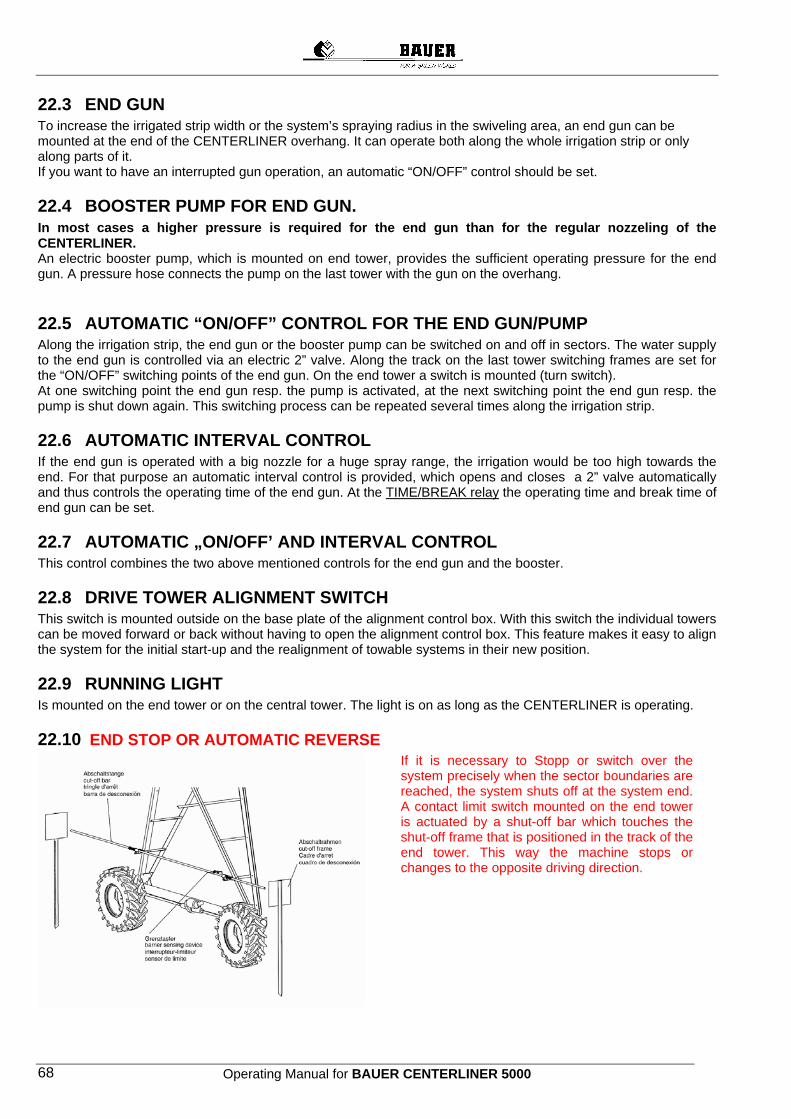
Operating Manual for BAUER CENTERLINER 5000 68
22.3 END GUN To increase the irrigated strip width or the system’s spraying radius in the swiveling area, an end gun can be mounted at the end of the CENTERLINER overhang. It can operate both along the whole irrigation strip or only along parts of it. If you want to have an interrupted gun operation, an automatic “ON/OFF” control should be set.
22.4 BOOSTER PUMP FOR END GUN. In most cases a higher pressure is required for the end gun than for the regular nozzeling of the CENTERLINER. An electric booster pump, which is mounted on end tower, provides the sufficient operating pressure for the end gun. A pressure hose connects the pump on the last tower with the gun on the overhang.
22.5 AUTOMATIC “ON/OFF” CONTROL FOR THE END GUN/PUMP Along the irrigation strip, the end gun or the booster pump can be switched on and off in sectors. The water supply to the end gun is controlled via an electric 2” valve. Along the track on the last tower switching frames are set for the “ON/OFF” switching points of the end gun. On the end tower a switch is mounted (turn switch). At one switching point the end gun resp. the pump is activated, at the next switching point the end gun resp. the pump is shut down again. This switching process can be repeated several times along the irrigation strip.
22.6 AUTOMATIC INTERVAL CONTROL If the end gun is operated with a big nozzle for a huge spray range, the irrigation would be too high towards the end. For that purpose an automatic interval control is provided, which opens and closes a 2” valve automatically and thus controls the operating time of the end gun. At the TIME/BREAK relay the operating time and break time of end gun can be set.
22.7 AUTOMATIC „ON/OFF’ AND INTERVAL CONTROL This control combines the two above mentioned controls for the end gun and the booster.
22.8 DRIVE TOWER ALIGNMENT SWITCH This switch is mounted outside on the base plate of the alignment control box. With this switch the individual towers can be moved forward or back without having to open the alignment control box. This feature makes it easy to align the system for the initial start-up and the realignment of towable systems in their new position.
22.9 RUNNING LIGHT Is mounted on the end tower or on the central tower. The light is on as long as the CENTERLINER is operating.
22.10 END STOP OR AUTOMATIC REVERSE
If it is necessary to Stopp or switch over the system precisely when the sector boundaries are reached, the system shuts off at the system end. A contact limit switch mounted on the end tower is actuated by a shut-off bar which touches the shut-off frame that is positioned in the track of the end tower. This way the machine stops or changes to the opposite driving direction.
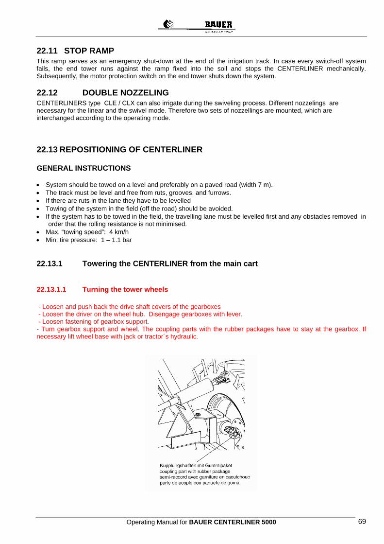
Operating Manual for BAUER CENTERLINER 5000 69
22.11 STOP RAMP This ramp serves as an emergency shut-down at the end of the irrigation track. In case every switch-off system fails, the end tower runs against the ramp fixed into the soil and stops the CENTERLINER mechanically. Subsequently, the motor protection switch on the end tower shuts down the system.
22.12 DOUBLE NOZZELING CENTERLINERS type CLE / CLX can also irrigate during the swiveling process. Different nozzelings are necessary for the linear and the swivel mode. Therefore two sets of nozzellings are mounted, which are interchanged according to the operating mode.
22.13 REPOSITIONING OF CENTERLINER GENERAL INSTRUCTIONS • System should be towed on a level and preferably on a paved road (width 7 m). • The track must be level and free from ruts, grooves, and furrows. • If there are ruts in the lane they have to be levelled • Towing of the system in the field (off the road) should be avoided. • If the system has to be towed in the field, the travelling lane must be levelled first and any obstacles removed in
order that the rolling resistance is not minimised. • Max. “towing speed”: 4 km/h • Min. tire pressure: 1 – 1.1 bar
22.13.1 Towering the CENTERLINER from the main cart
22.13.1.1 Turning the tower wheels - Loosen and push back the drive shaft covers of the gearboxes - Loosen the driver on the wheel hub. Disengage gearboxes with lever. - Loosen fastening of gearbox support. - Turn gearbox support and wheel. The coupling parts with the rubber packages have to stay at the gearbox. If necessary lift wheel base with jack or tractor´s hydraulic.
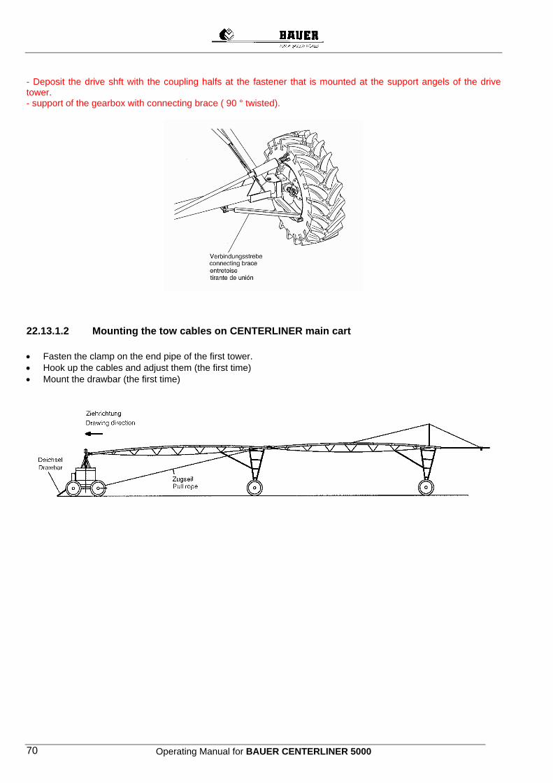
Operating Manual for BAUER CENTERLINER 5000 70
- Deposit the drive shft with the coupling halfs at the fastener that is mounted at the support angels of the drive tower. - support of the gearbox with connecting brace ( 90 ° twisted).
22.13.1.2 Mounting the tow cables on CENTERLINER main cart • Fasten the clamp on the end pipe of the first tower. • Hook up the cables and adjust them (the first time) • Mount the drawbar (the first time)
Operating Manual for BAUER CENTERLINER 5000 71
23 ELECTRIC SWITCHING PLANS
23.1 CENTERLINER CONTROL PANEL STANDARD 23.1.1 Control Panel standard CLS-infeed, sheet 1 23.1.2 Control Panel standard-CLS infeed, sheet 2 23.1.3 Switching Plan, Positional Control CLS 23.1.4 Control Panel standard switching plan, sheet 1 23.1.5 Control Panel standard switching plan, sheet 2 23.1.6 Control Panel standard switching plan, sheet 3 23.1.7 Control Panel standard switching plan, sheet 4 23.1.8 Control Panel standard switching plan, sheet 5
23.2 CENTERLINER CONTROL PANEL SELECT 23.2.1 Control Panel Select CLE, infeed, sheet 1 23.2.2 Control Panel Select CLE, infeed, sheet 2 23.2.3 Control Panel Select CLE, infeed, sheet 3 23.2.4 Control Panel Select CLE, switching plan, sheet 1 23.2.5 Control Panel Select CLE, switching plan, sheet 2 23.2.6 Control Panel Select CLE, switching plan, sheet 3 23.2.7 Control Panel Select CLE, switching plan, sheet 4 23.2.8 Control Panel Select CLE, switching plan, sheet 5 23.2.9 Control Panel Select CLE, switching plan, sheet 6 23.2.10 Control Panel Select CLE, switching plan, sheet 7 23.2.11 Control Panel Select CLE, switching plan, sheet 8 23.2.12 Control Panel Select CLE, switching plan, sheet 9 23.2.13 Control Panel Select CLE, switching plan, sheet 10 23.2.14 Control Panel Select CLE, switching plan, sheet 11 23.2.15 Control Panel Select CLE, switching plan, sheet 12 23.2.16 Control Panel Select CLE, switching plan, sheet 13 23.2.17 Control Panel Select CLX, infeed, sheet 1 23.2.18 Control Panel Select CLX, infeed, sheet 2 23.2.19 Control Panel Select CLX, infeed, sheet 3 23.2.20 Control Panel Select CLX, switching plan, sheet 1 23.2.21 Control Panel Select CLX, switching plan, sheet 11 All the other switching plans for CLX are the same as for CLE
23.3 CENTERLINER CONTROL PANEL, POSITONAL CONTROL 23.3.1 Switching Plan, Positional Control
23.4 CENTERLINER CONTROL PANEL, LINEAR CONTROL 23.4.1 Switching Plan Linear, Control - Furrow Guidance 23.4.2 Switching Plan Linear, Cable Guidance
23.5 CENTERLINER ALIGNMENT CONTROL 23.5.1 Alignment Control Standard 23.5.2 Alignment Control with Tower Adjusting Switch 23.5.3 Alignment Control with Monitoring Device 23.5.4 Alignment Control with Monitoring Device and Tower Adjusting Switch 23.5.5 End Control 23.5.6 End Control with Tower Alignment Switch 23.5.7 Booster Pump
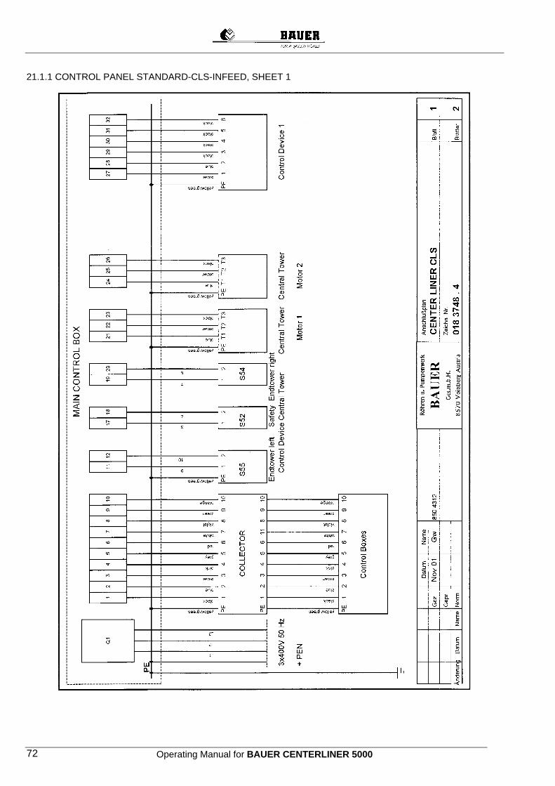
Operating Manual for BAUER CENTERLINER 5000 72
21.1.1 CONTROL PANEL STANDARD-CLS-INFEED, SHEET 1
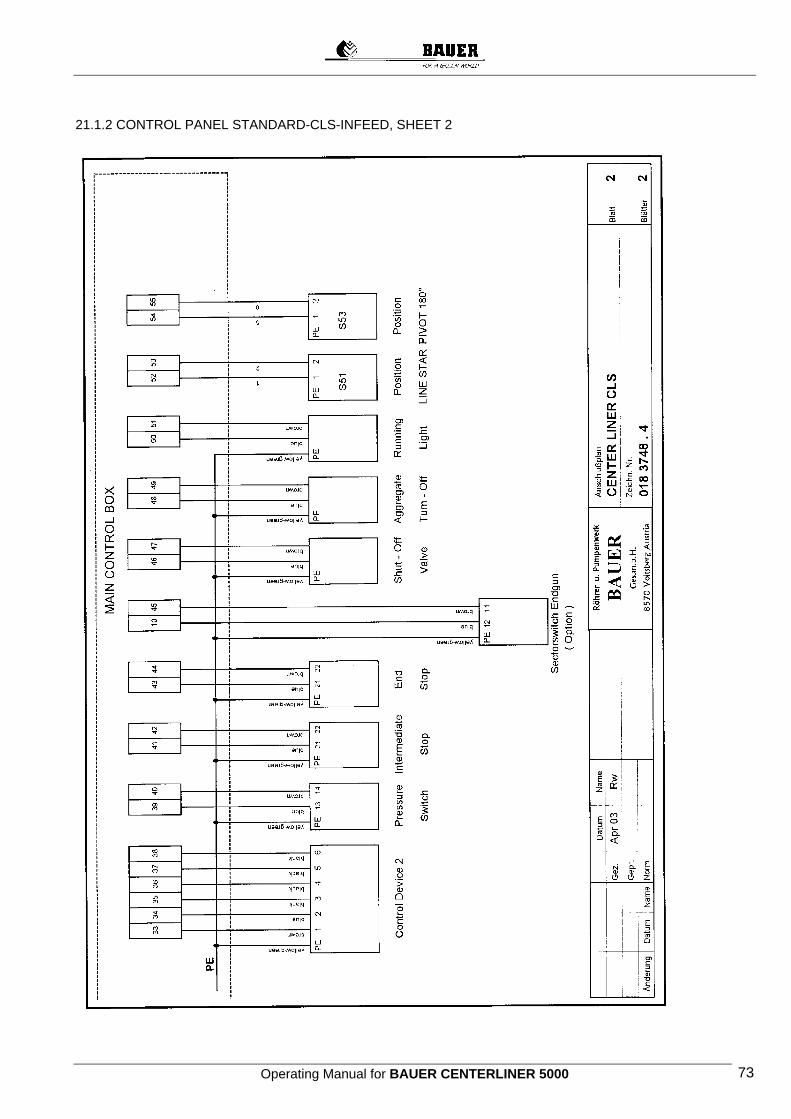
Operating Manual for BAUER CENTERLINER 5000 73
21.1.2 CONTROL PANEL STANDARD-CLS-INFEED, SHEET 2

Operating Manual for BAUER CENTERLINER 5000 74
21.1.3 SWITCHING PLAN, POSITIONAL CONTROL CLS
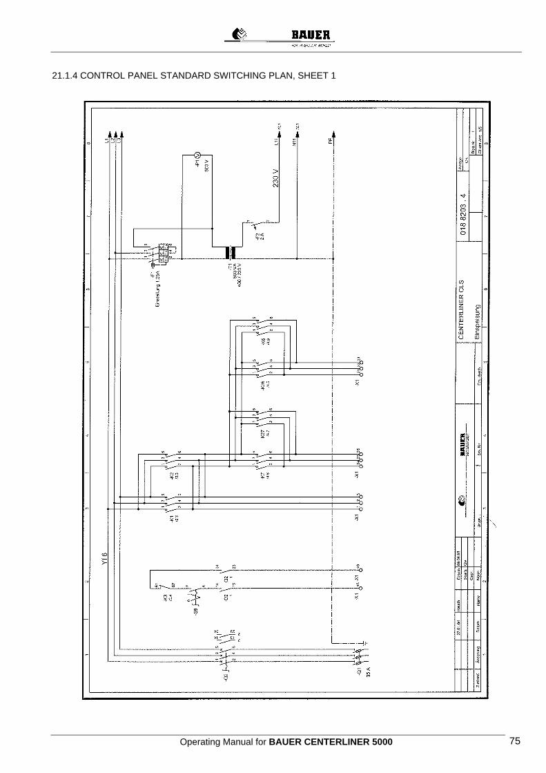
Operating Manual for BAUER CENTERLINER 5000 75
21.1.4 CONTROL PANEL STANDARD SWITCHING PLAN, SHEET 1

Operating Manual for BAUER CENTERLINER 5000 76
21.1.5 CONTROL PANEL STANDARD SWITCHING PLAN, SHEET 2
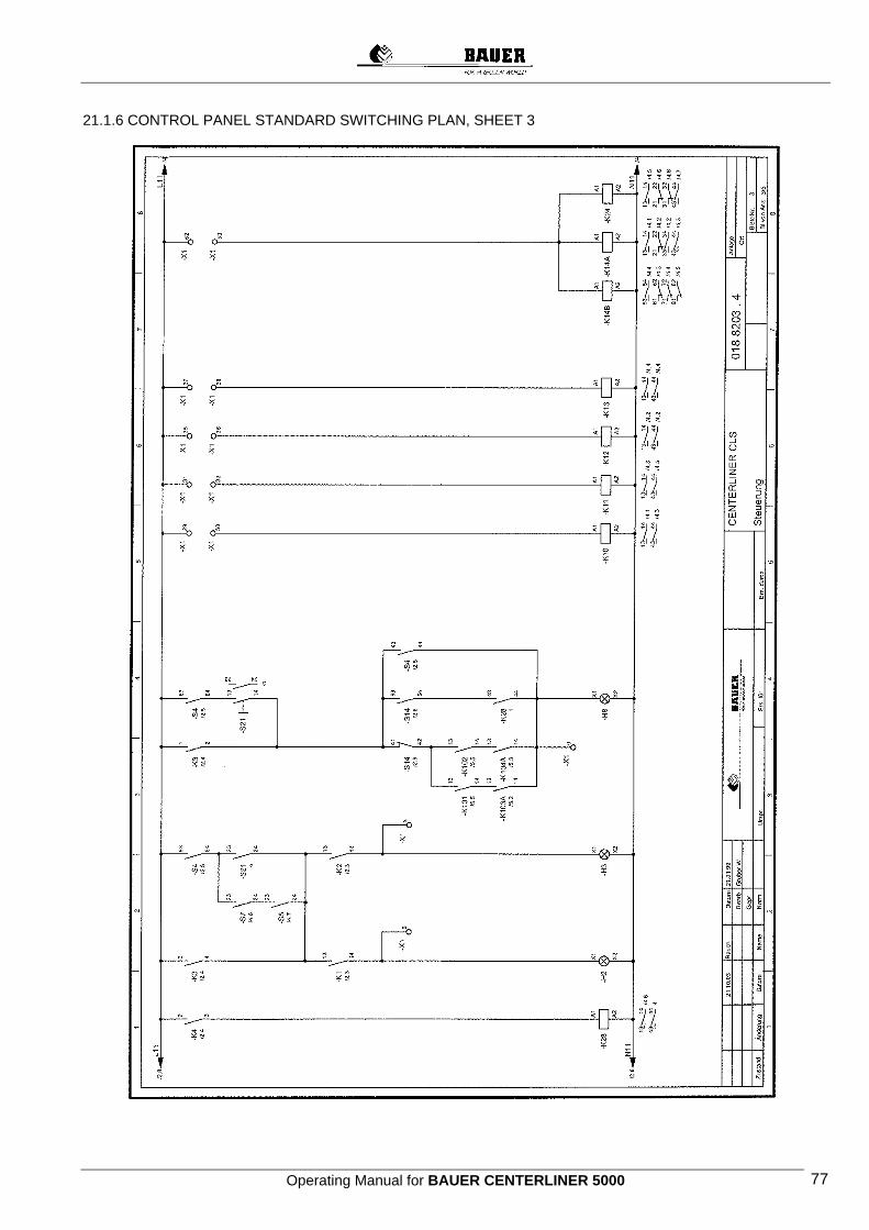
Operating Manual for BAUER CENTERLINER 5000 77
21.1.6 CONTROL PANEL STANDARD SWITCHING PLAN, SHEET 3

Operating Manual for BAUER CENTERLINER 5000 78
21.1.7. CONTROL PANEL STANDARD SWITCHING PLAN, SHEET 4
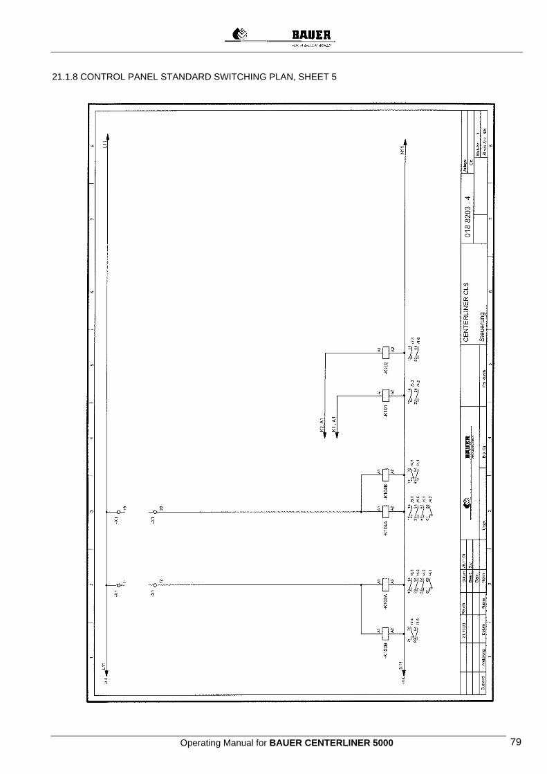
Operating Manual for BAUER CENTERLINER 5000 79
21.1.8 CONTROL PANEL STANDARD SWITCHING PLAN, SHEET 5
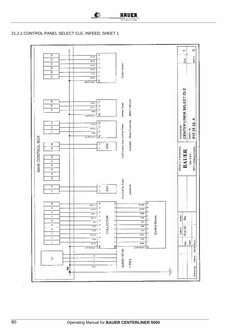
Operating Manual for BAUER CENTERLINER 5000 80
21.2.1 CONTROL PANEL SELECT CLE, INFEED, SHEET 1

Operating Manual for BAUER CENTERLINER 5000 81
21.2.2 CONTROL PANEL SELECT CLE, INFEED, SHEET 2
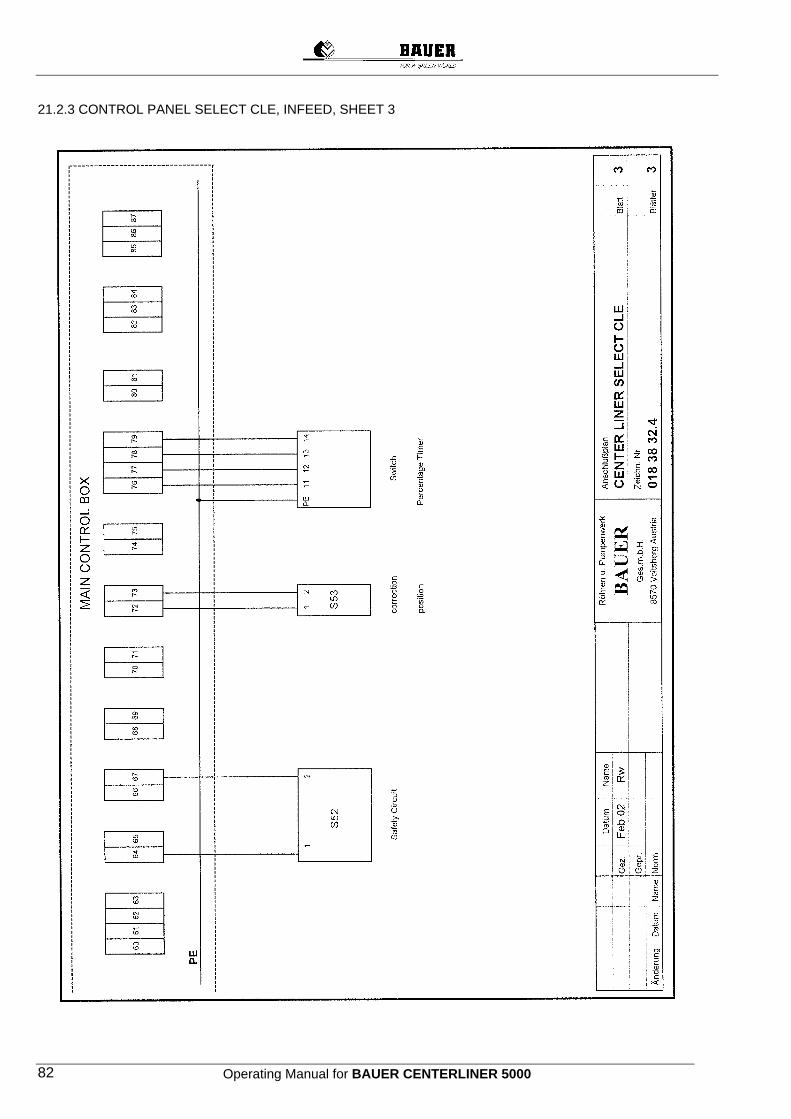
Operating Manual for BAUER CENTERLINER 5000 82
21.2.3 CONTROL PANEL SELECT CLE, INFEED, SHEET 3
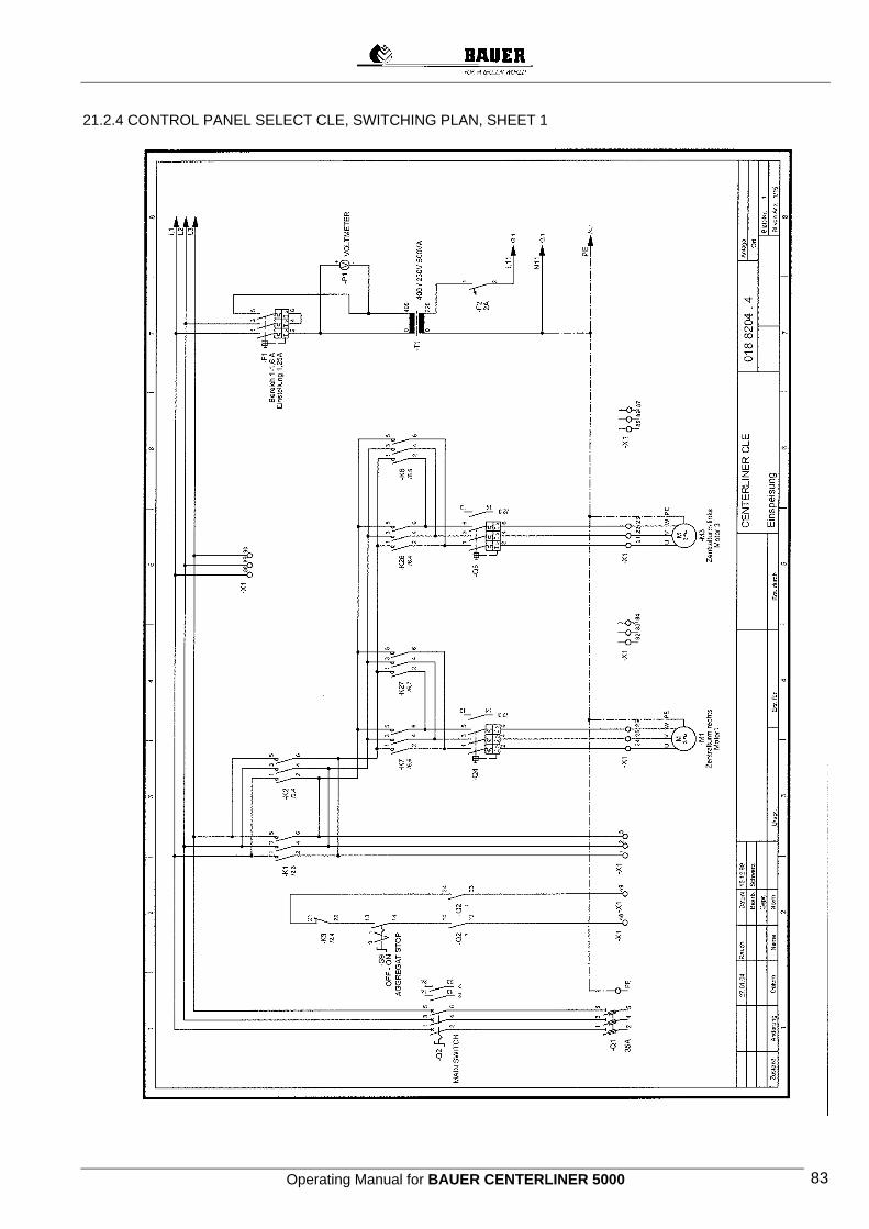
Operating Manual for BAUER CENTERLINER 5000 83
21.2.4 CONTROL PANEL SELECT CLE, SWITCHING PLAN, SHEET 1

Operating Manual for BAUER CENTERLINER 5000 84
21.2.5 CONTROL PANEL SELECT CLE, SWITCHING PLAN, SHEET 2
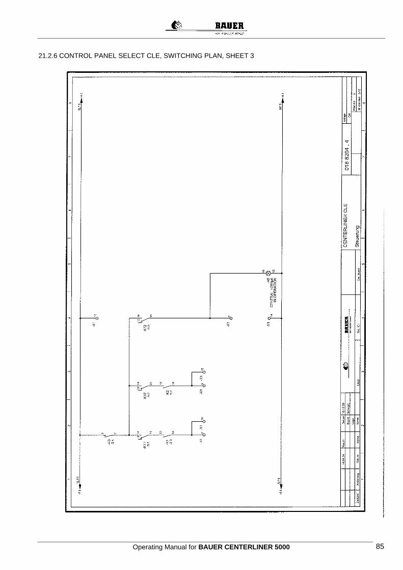
Operating Manual for BAUER CENTERLINER 5000 85
21.2.6 CONTROL PANEL SELECT CLE, SWITCHING PLAN, SHEET 3
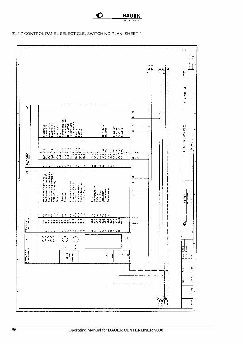
Operating Manual for BAUER CENTERLINER 5000 86
21.2.7 CONTROL PANEL SELECT CLE, SWITCHING PLAN, SHEET 4
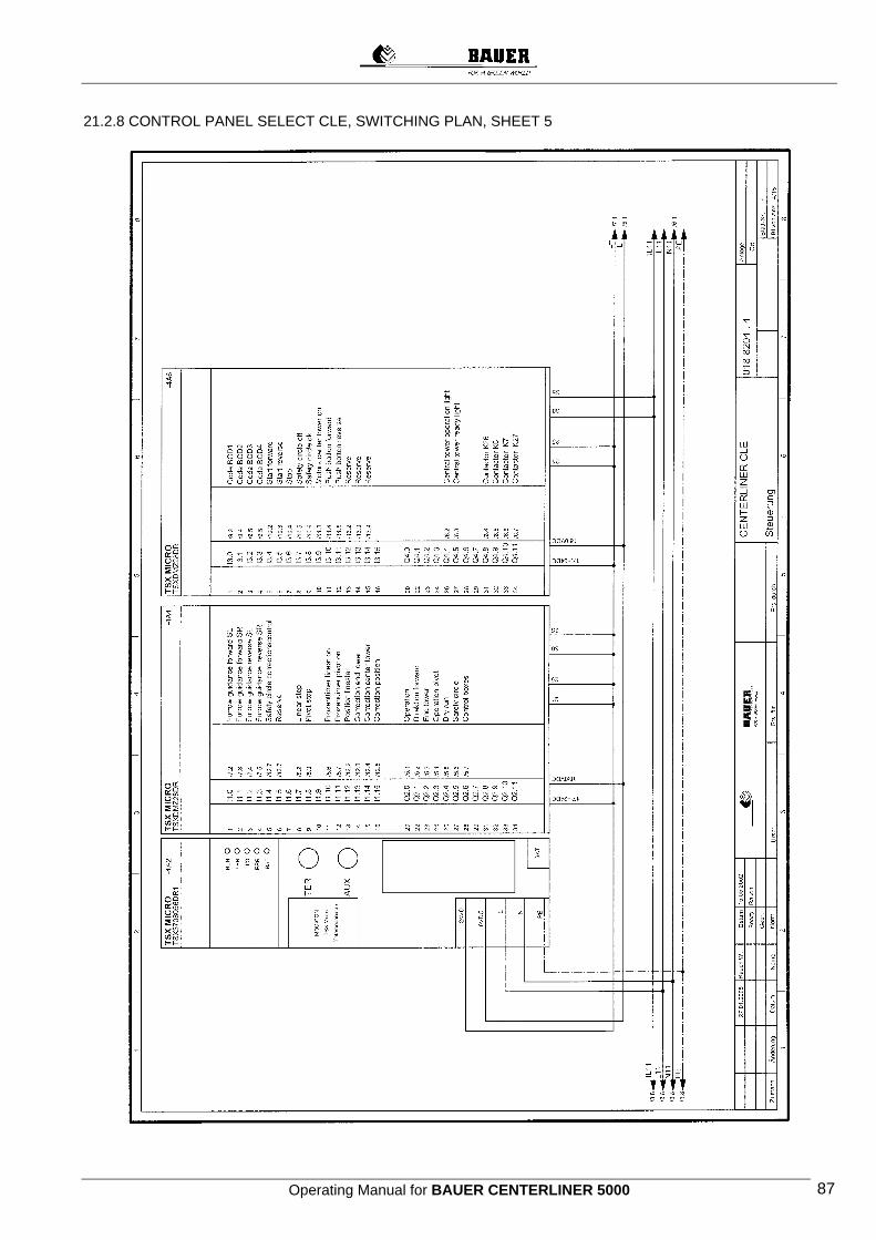
Operating Manual for BAUER CENTERLINER 5000 87
21.2.8 CONTROL PANEL SELECT CLE, SWITCHING PLAN, SHEET 5
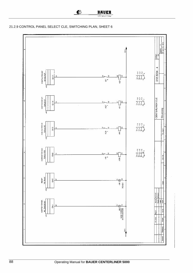
Operating Manual for BAUER CENTERLINER 5000 88
21.2.9 CONTROL PANEL SELECT CLE, SWITCHING PLAN, SHEET 6
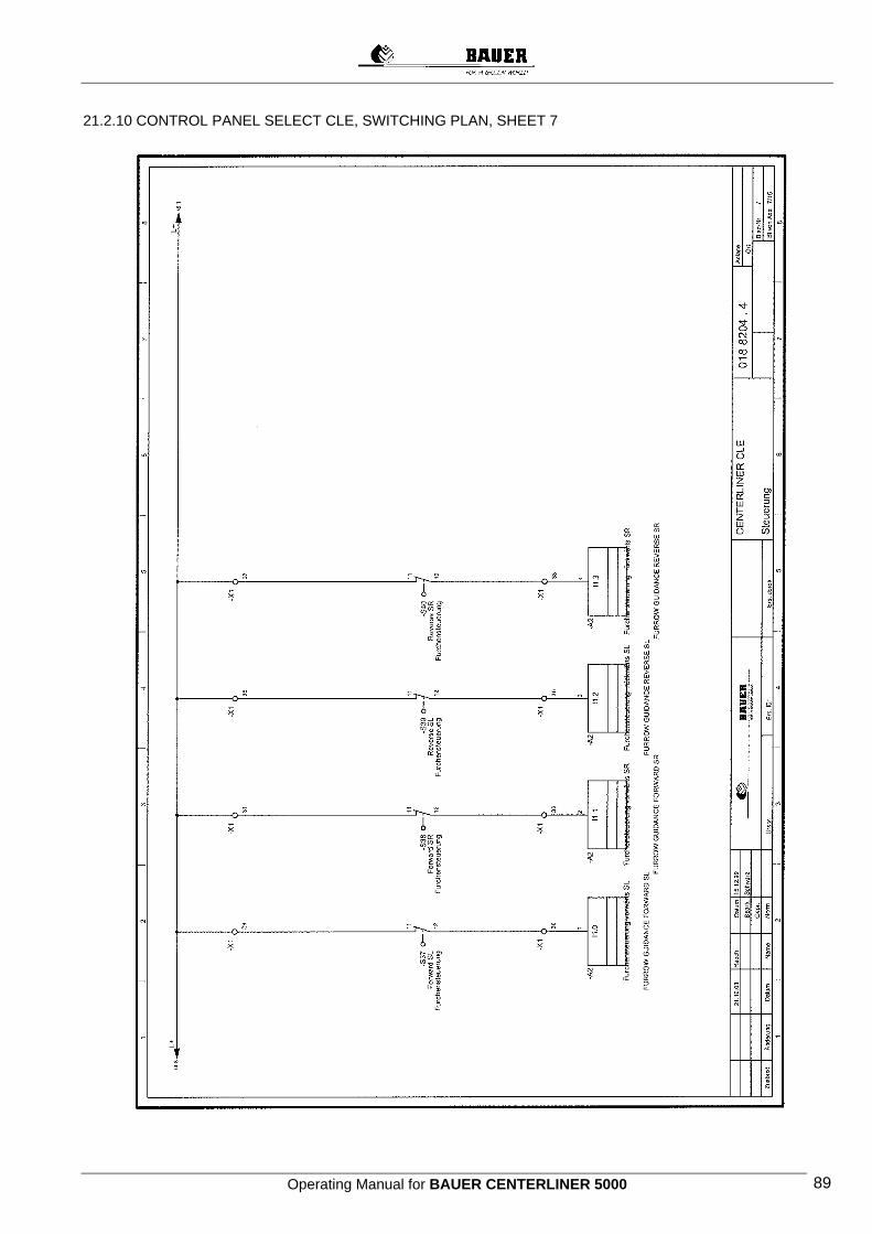
Operating Manual for BAUER CENTERLINER 5000 89
21.2.10 CONTROL PANEL SELECT CLE, SWITCHING PLAN, SHEET 7
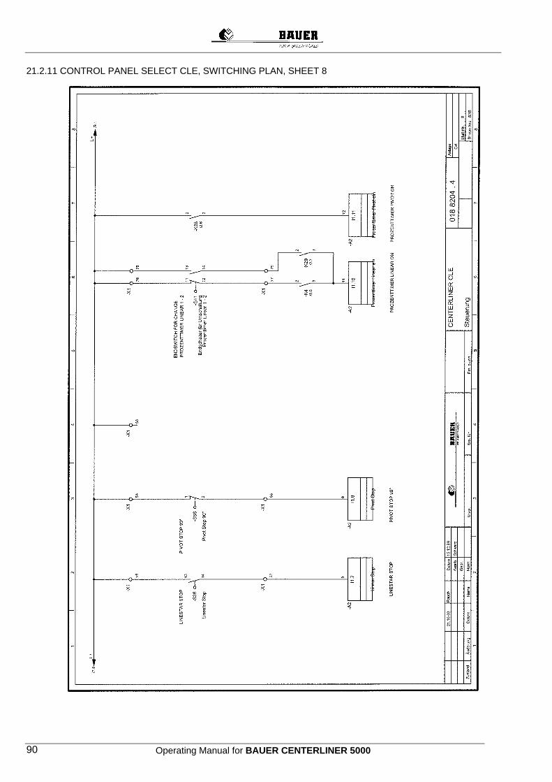
Operating Manual for BAUER CENTERLINER 5000 90
21.2.11 CONTROL PANEL SELECT CLE, SWITCHING PLAN, SHEET 8

Operating Manual for BAUER CENTERLINER 5000 91
21.2.12 CONTROL PANEL SELECT CLE, SWITCHING PLAN, SHEET 9
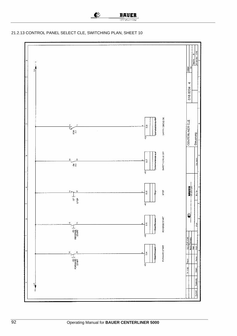
Operating Manual for BAUER CENTERLINER 5000 92
21.2.13 CONTROL PANEL SELECT CLE, SWITCHING PLAN, SHEET 10

Operating Manual for BAUER CENTERLINER 5000 93
21.2.14 CONTROL PANEL SELECT CLE, SWITCHING PLAN, SHEET 11

Operating Manual for BAUER CENTERLINER 5000 94
21.2.15 CONTROL PANEL SELECT CLE, SWITCHING PLAN, SHEET 12
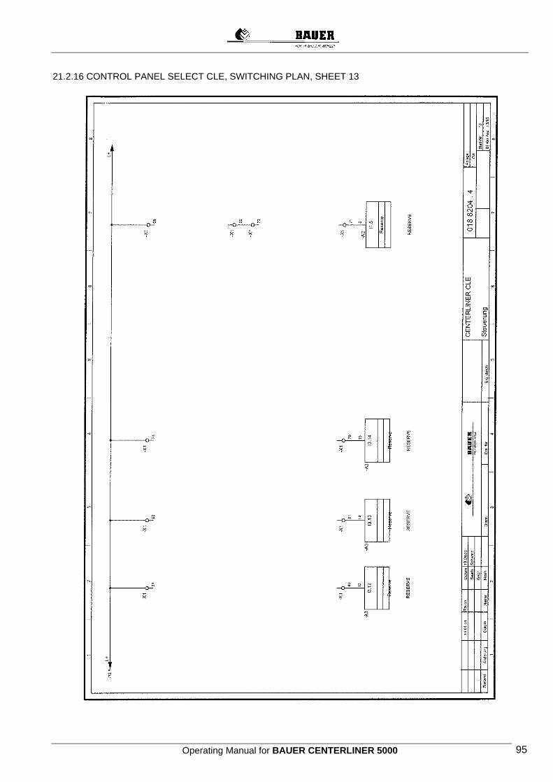
Operating Manual for BAUER CENTERLINER 5000 95
21.2.16 CONTROL PANEL SELECT CLE, SWITCHING PLAN, SHEET 13
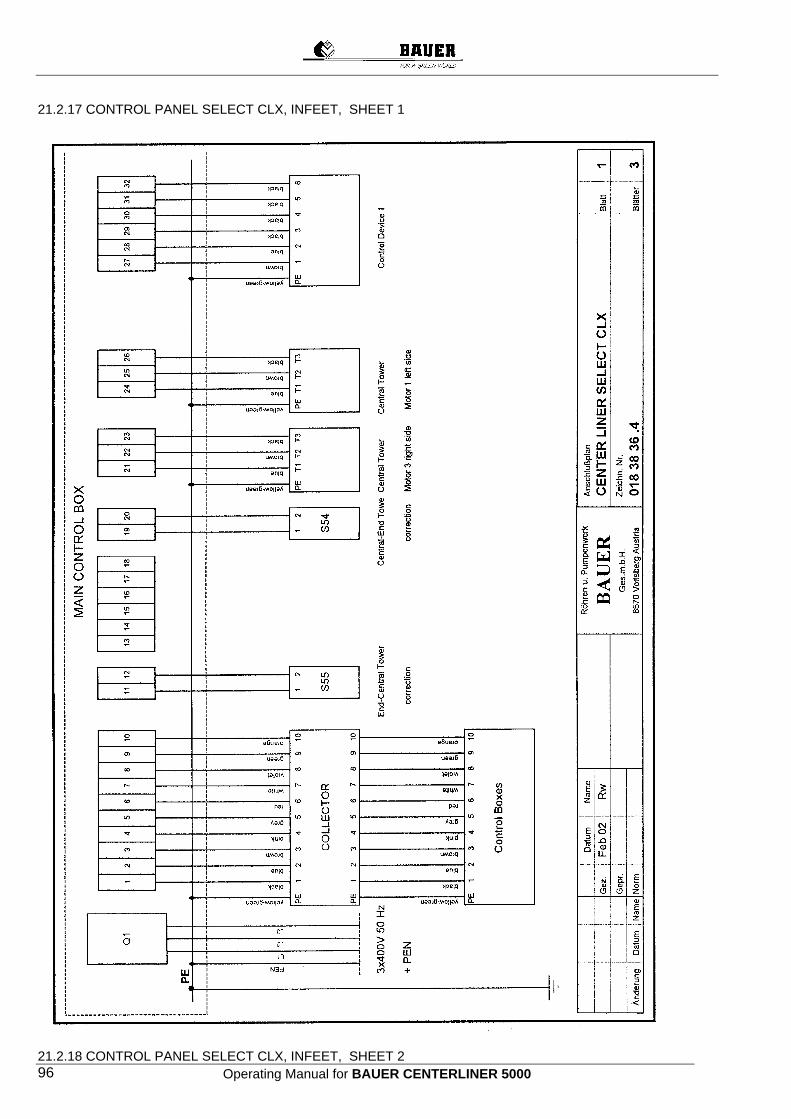
Operating Manual for BAUER CENTERLINER 5000 96
21.2.17 CONTROL PANEL SELECT CLX, INFEET, SHEET 1
21.2.18 CONTROL PANEL SELECT CLX, INFEET, SHEET 2
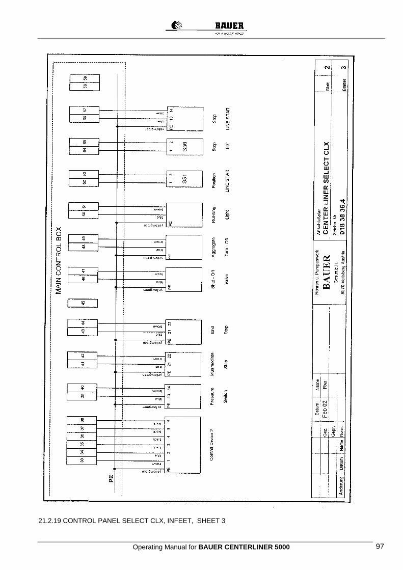
Operating Manual for BAUER CENTERLINER 5000 97
21.2.19 CONTROL PANEL SELECT CLX, INFEET, SHEET 3
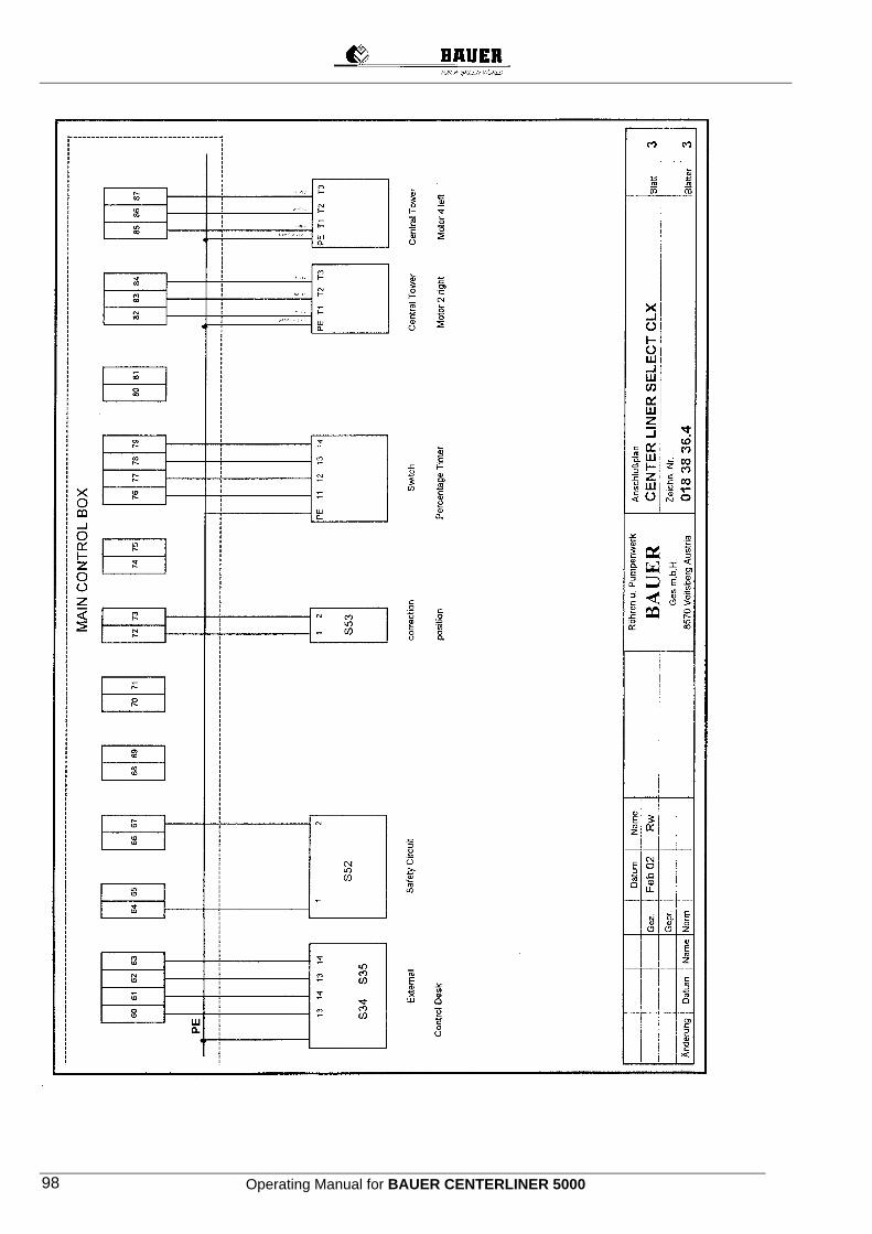
Operating Manual for BAUER CENTERLINER 5000 98
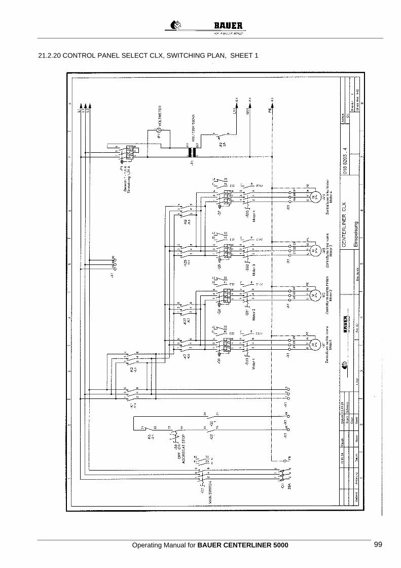
Operating Manual for BAUER CENTERLINER 5000 99
21.2.20 CONTROL PANEL SELECT CLX, SWITCHING PLAN, SHEET 1
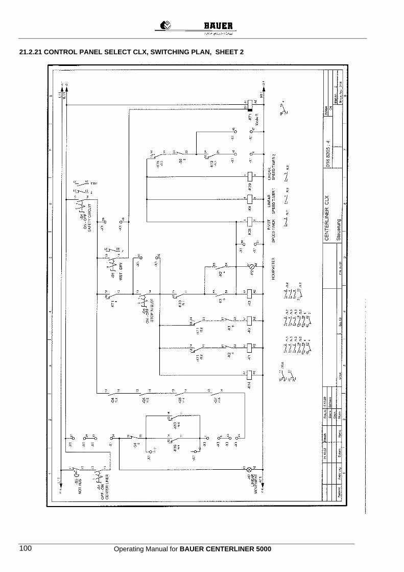
Operating Manual for BAUER CENTERLINER 5000 100
21.2.21 CONTROL PANEL SELECT CLX, SWITCHING PLAN, SHEET 2
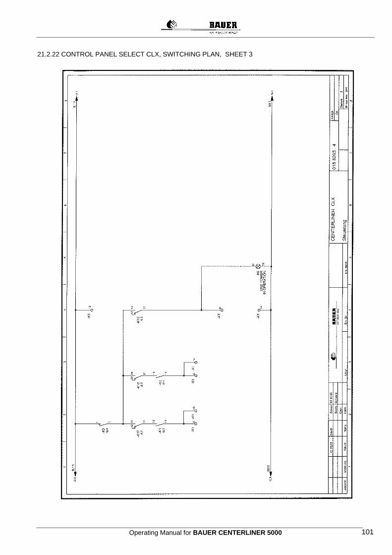
Operating Manual for BAUER CENTERLINER 5000 101
21.2.22 CONTROL PANEL SELECT CLX, SWITCHING PLAN, SHEET 3
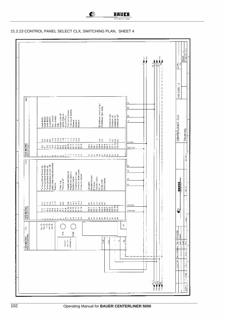
Operating Manual for BAUER CENTERLINER 5000 102
21.2.23 CONTROL PANEL SELECT CLX, SWITCHING PLAN, SHEET 4
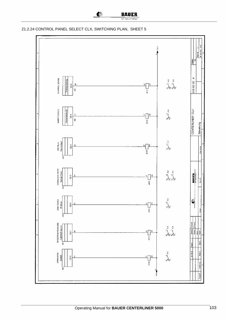
Operating Manual for BAUER CENTERLINER 5000 103
21.2.24 CONTROL PANEL SELECT CLX, SWITCHING PLAN, SHEET 5
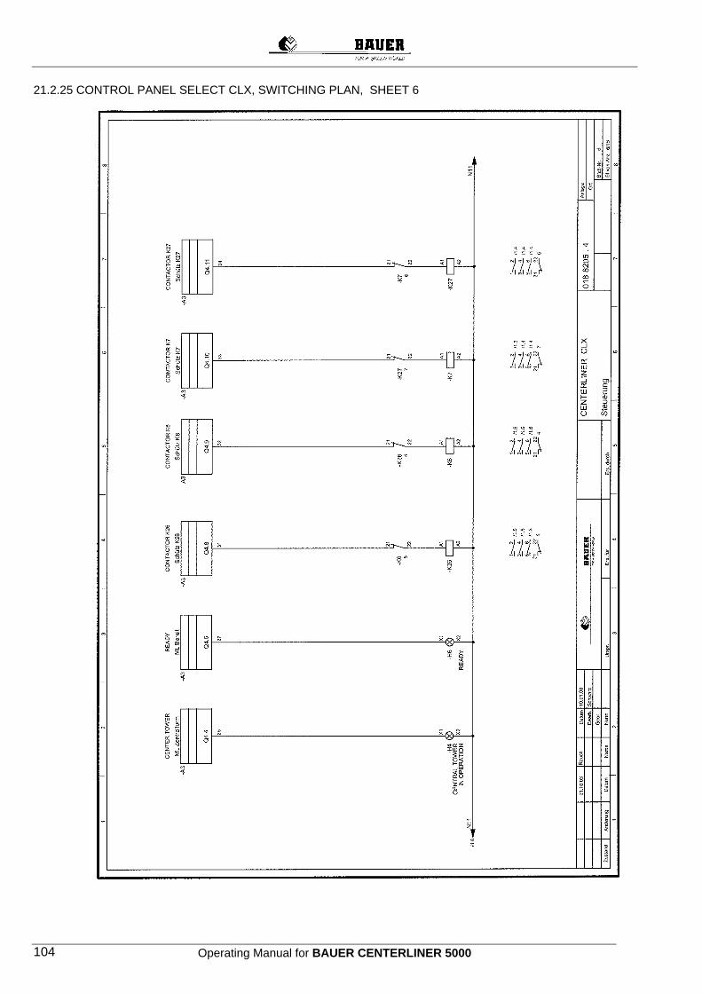
Operating Manual for BAUER CENTERLINER 5000 104
21.2.25 CONTROL PANEL SELECT CLX, SWITCHING PLAN, SHEET 6
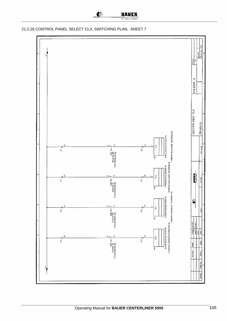
Operating Manual for BAUER CENTERLINER 5000 105
21.2.26 CONTROL PANEL SELECT CLX, SWITCHING PLAN, SHEET 7

Operating Manual for BAUER CENTERLINER 5000 106
21.2.27 CONTROL PANEL SELECT CLX, SWITCHING PLAN, SHEET 8
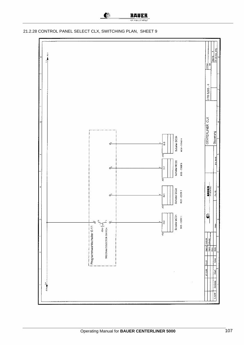
Operating Manual for BAUER CENTERLINER 5000 107
21.2.28 CONTROL PANEL SELECT CLX, SWITCHING PLAN, SHEET 9

Operating Manual for BAUER CENTERLINER 5000 108
21.2.29 CONTROL PANEL SELECT CLX, SWITCHING PLAN, SHEET 10
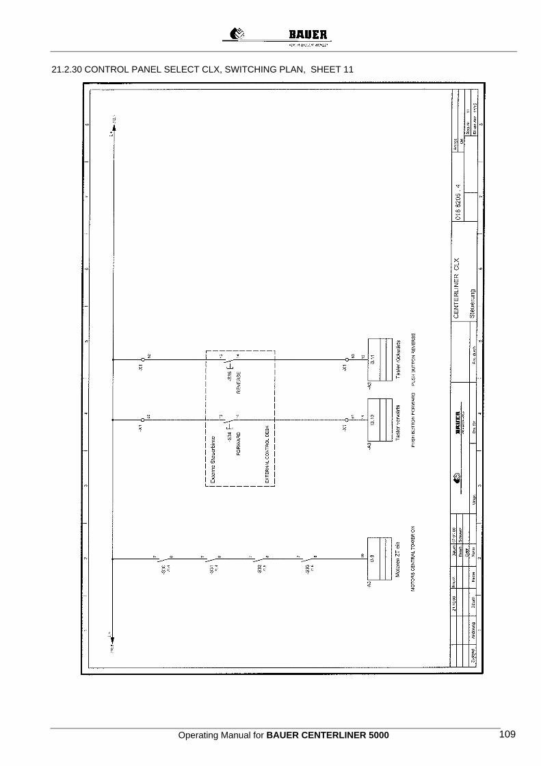
Operating Manual for BAUER CENTERLINER 5000 109
21.2.30 CONTROL PANEL SELECT CLX, SWITCHING PLAN, SHEET 11
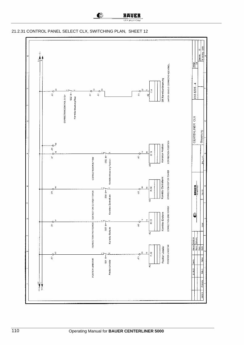
Operating Manual for BAUER CENTERLINER 5000 110
21.2.31 CONTROL PANEL SELECT CLX, SWITCHING PLAN, SHEET 12
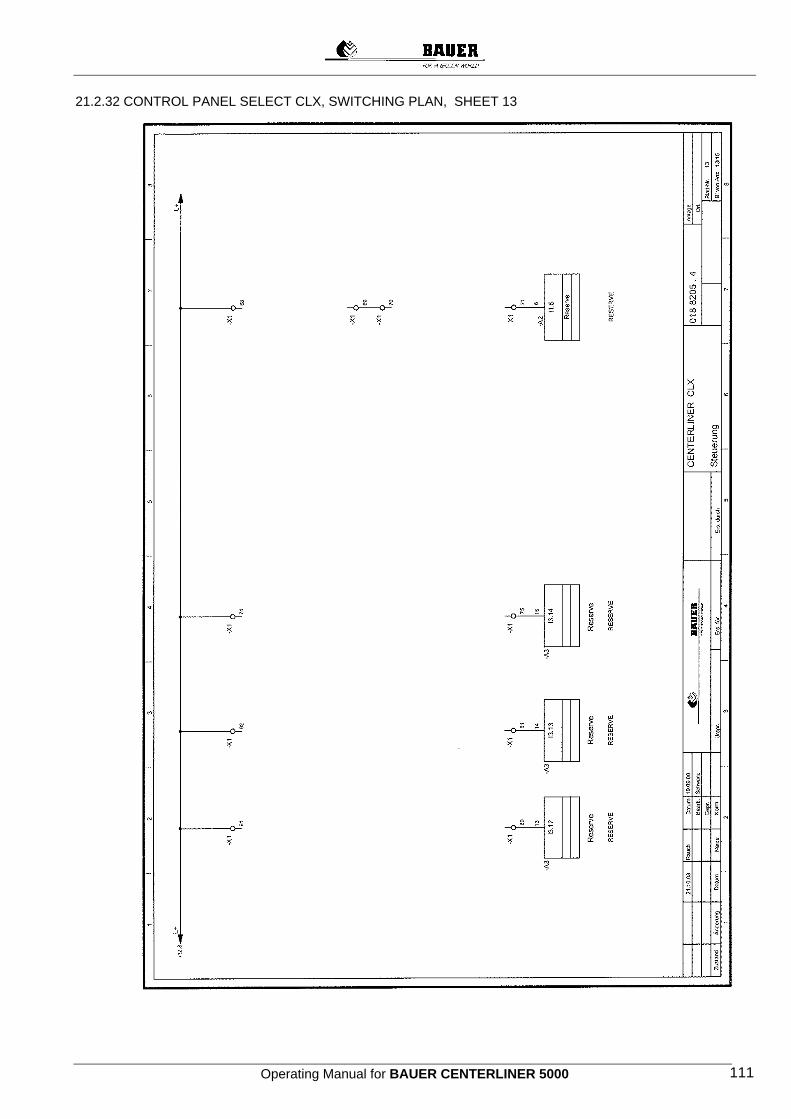
Operating Manual for BAUER CENTERLINER 5000 111
21.2.32 CONTROL PANEL SELECT CLX, SWITCHING PLAN, SHEET 13
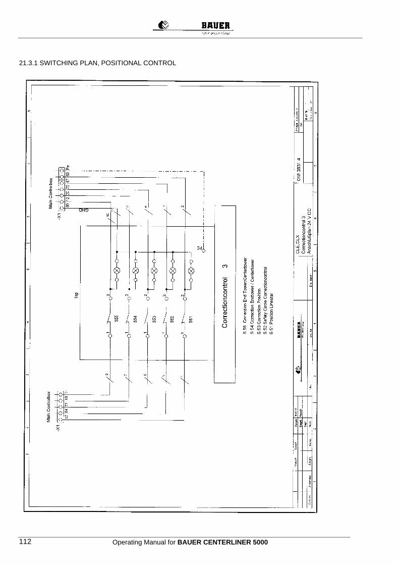
Operating Manual for BAUER CENTERLINER 5000 112
21.3.1 SWITCHING PLAN, POSITIONAL CONTROL
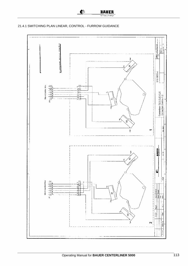
Operating Manual for BAUER CENTERLINER 5000 113
21.4.1 SWITCHING PLAN LINEAR, CONTROL - FURROW GUIDANCE
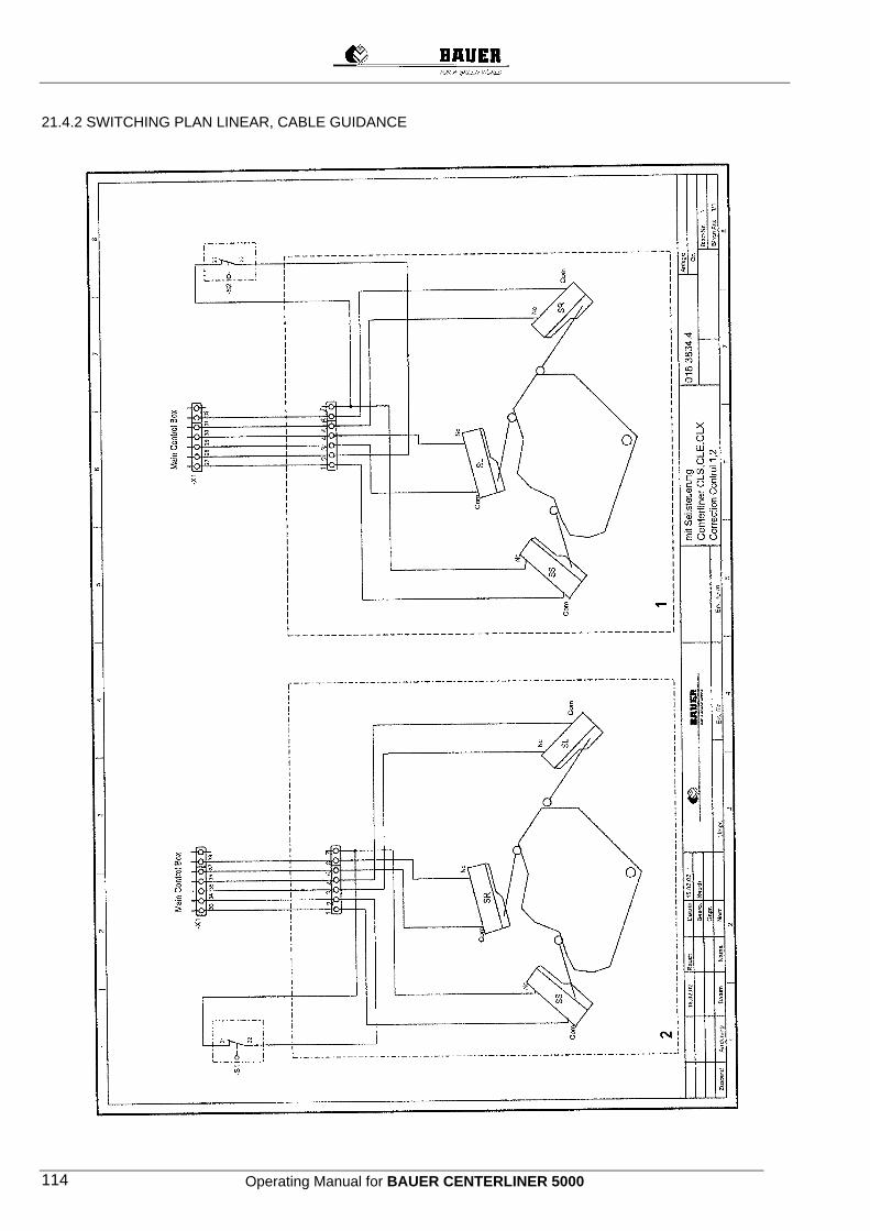
Operating Manual for BAUER CENTERLINER 5000 114
21.4.2 SWITCHING PLAN LINEAR, CABLE GUIDANCE
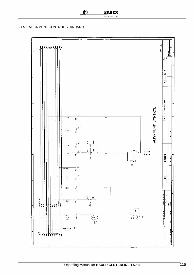
Operating Manual for BAUER CENTERLINER 5000 115
21.5.1 ALIGNMENT CONTROL STANDARD
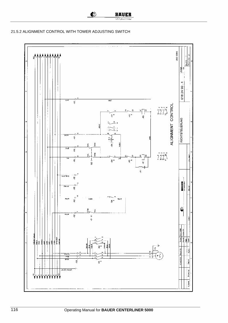
Operating Manual for BAUER CENTERLINER 5000 116
21.5.2 ALIGNMENT CONTROL WITH TOWER ADJUSTING SWITCH

Operating Manual for BAUER CENTERLINER 5000 117
21.5.3 ALIGNMENT CONTROL WITH MONITORING DEVICE
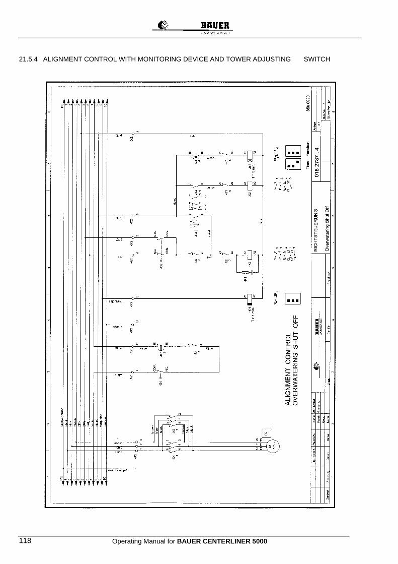
Operating Manual for BAUER CENTERLINER 5000 118
21.5.4 ALIGNMENT CONTROL WITH MONITORING DEVICE AND TOWER ADJUSTING SWITCH
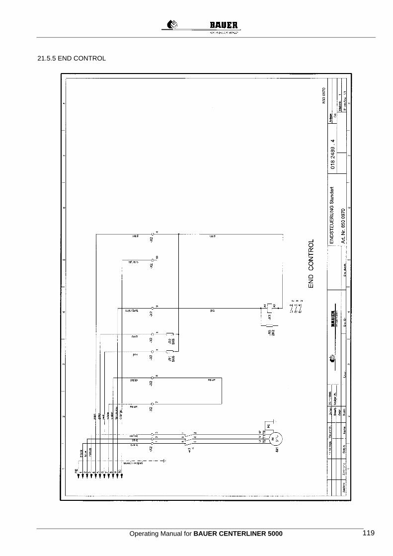
Operating Manual for BAUER CENTERLINER 5000 119
21.5.5 END CONTROL
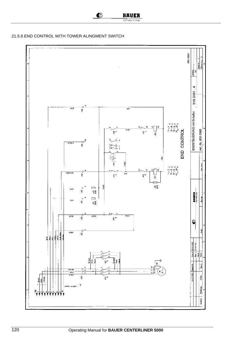
Operating Manual for BAUER CENTERLINER 5000 120
21.5.6 END CONTROL WITH TOWER ALINGMENT SWITCH

Operating Manual for BAUER CENTERLINER 5000 121
21.5.7 CONTROL BOX - BOOSTER PUMP
Operating Manual for BAUER CENTERLINER 5000 122
24 Service – Proof Has been done
Yes No Date Operating hours Proof for the accomplished service
Part -Service
Part -Service
Part -Service
Part -Service
Part -Service
Part -Service
Part -Service
Part -Service
Part -Service
Part -Service
Part-Service
Oil change-Service
Annual-Service Has been done
Yes No Date Operating hours Proof for the accomplished service
Part -Service
Part -Service
Part -Service
Part -Service
Part -Service
Part -Service
Part -Service
Part -Service
Part -Service
Part -Service
Part -Service
Oil change-Service
Annual Service
Operating Manual for BAUER CENTERLINER 5000 123
Has been done
Yes No Date Operating hours Proof for the accomplished service
Part -Service
Part -Service
Part -Service
Part -Service
Part -Service
Part -Service
Part -Service
Part -Service
Part -Service
Part -Service
Part-Service
Oil change-Service
Annual-Service Has been done
Yes No Date Operating hours Proof for the accomplished service
Part -Service
Part -Service
Part -Service
Part -Service
Part -Service
Part -Service
Part -Service
Part -Service
Part -Service
Part -Service
Part -Service
Oil change-Service
Annual Service
Operating Manual for BAUER CENTERLINER 5000 124
Has been done
Yes No Date Operating hours Proof for the accomplished service
Part -Service
Part -Service
Part -Service
Part -Service
Part -Service
Part -Service
Part -Service
Part -Service
Part -Service
Part -Service
Part-Service
Oil change-Service
Annual-Service Has been done
Yes No Date Operating hours Proof for the accomplished service
Part -Service
Part -Service
Part -Service
Part -Service
Part -Service
Part -Service
Part -Service
Part -Service
Part -Service
Part -Service
Part -Service
Oil change-Service
Annual Service

Operating Manual for BAUER CENTERLINER 5000 125
Has been done
Yes No Date Operating hours Proof for the accomplished service
Part -Service
Part -Service
Part -Service
Part -Service
Part -Service
Part -Service
Part -Service
Part -Service
Part -Service
Part -Service
Part-Service
Oil change-Service
Annual-Service Has been done
Yes No Date Operating hours Proof for the accomplished service
Part -Service
Part -Service
Part -Service
Part -Service
Part -Service
Part -Service
Part -Service
Part -Service
Part -Service
Part -Service
Part -Service
Oil change-Service
Annual Service
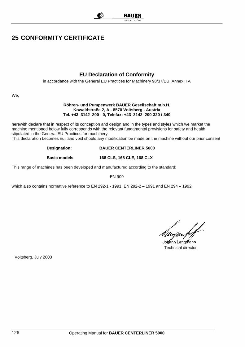
Operating Manual for BAUER CENTERLINER 5000 126
25 CONFORMITY CERTIFICATE
EU Declaration of Conformity in accordance with the General EU Practices for Machinery 98/37/EU, Annex II A
We,
Röhren- und Pumpenwerk BAUER Gesellschaft m.b.H. Kowaldstraße 2, A - 8570 Voitsberg - Austria
Tel. +43 3142 200 - 0, Telefax: +43 3142 200-320 /-340
herewith declare that in respect of its conception and design and in the types and styles which we market the machine mentioned below fully corresponds with the relevant fundamental provisions for safety and health stipulated in the General EU Practices for machinery. This declaration becomes null and void should any modification be made on the machine without our prior consent
Designation: BAUER CENTERLINER 5000 Basic models: 168 CLS, 168 CLE, 168 CLX
This range of machines has been developed and manufactured according to the standard:
EN 909
which also contains normative reference to EN 292-1 - 1991, EN 292-2 – 1991 and EN 294 – 1992.
Technical director
Voitsberg, July 2003