battery desulfator report part 1 2003/5/14 · 2014-02-24 · reaction efficiency of the battery. as...
TRANSCRIPT

E2417 Project
Battery Desulfator Report Part 1
2003/5/14
Group member: Curtis Lin Harry Jao
1
Table of content: 1. Objective and Technical Function P. 3 2. Description of Car Battery P. 4 3. Complete chemical reaction for charging and discharging a car battery P. 5 4. Equipment list P. 6 5. Commercial product and Prototype 1’s layout P. 7 6. Details of parts list to build Prototype 1 P. 8 7. Prototype 2’s layout and Details of parts list to build Prototype 2 P. 9 8. Car battery pulse charging simulation test circuit by using current probe P. 10 9. Commercial product and Prototype 1’s output pulsing current’s waveform P. 11 10. Prototype 2’s output pulsing current’s waveform P.12 11. Reasons of using the design of Prototype 1 to do the final testing P.13 12. Expected and measured discharging time with and without using the desulfator
P.14 & P.15 13. Measured charging time with desulfator P.16 & P.17 14. Conclusion P.18

2
List of Figures: Figure 1: Setup of battery desulfator and 12V car battery P. 3 Figure 2: Commercial and Prototype 1 car battery desulfator (from AMOX Inc). P. 7 Figure 2(a): The Prototype 1 circuit we built P. 8 Figure 3: Prototype 2 car battery desulfator (from website). P. 9 Figure 4: Car battery pulse charging simulation test by using current probe P.10 Figure 5: Car battery pulse charging simulation test by using the scope’s function
MATH = CH1 – CH2 P.10 Figure 6: Commercial product’s output pulsing current P.11 Figure 7: Prototype 1’s output pulsing current P.11 Figure 8: Prototype 2’s output pulsing current P.12 Figure 9: Expected shape of waveform for Battery discharge depth VS voltage P.14 Figure 10: Discharging (BLACK) battery with and without using Prototype 1 desulfator P.15 Figure 11: Charging Current & Voltage wrt. Time P.16 Figure 12: Battery charging current characteristic P.17 List of Tables: Table 1: Equipment list P. 6 Table 2: Parts list of Prototype 1 P. 8 Table 3: Parts list of Prototype 2 P. 9 Table 4: Compare BLACK battery discharge depth with and without desulfator P.14 Table 5: Charging GREEN battery (without Desulfator) P.16 Table 6: Charging BLACK battery (with Desulfator) P.17 Appendix: Appendix A: Milestone Chart Appendix B: Bar Chart (Table 8 to Table 10)

3
Objective: To build a device that improves the sulfate problems in a 12 volts car battery. With the battery desulfator we built, the battery will have a longer lifetime for use. Technical Function: By generating a series of high amplitude current pulse (around 1 Amp) and charging it into the Lead acid battery, the function of battery desulfator that is used in conjunction (in parallel) with the conventional battery charger will activate the large lead sulfate crystals on the cathode plate and improve the charging chemical reaction efficiency of the battery. As a result of repetitive use of the battery desulfator, the lead sulfate crystal size is reduced and more sulfuric acid is returned to the battery solution. The car battery will have a longer lifetime for use.
Figure 1: Setup of battery desulfator and 12V car battery

4
Description of Car Battery: A car battery is formed with six smaller batteries that line up in series. This causes the voltages of each battery to add. The general way a battery works is that when an electronic circuit is connected to the battery, electrons are allowed to flow. Inside the battery, there are 3 important things: 1. There are 2 connectors that come out of the battery. They are called the cathode
and the anode. 2. There is also a solution that the cathode and the anode sit in.
During the normal operation, a chemical reaction occurs between the solution and the anode that releases electrons that flow through the circuit.
3. These reenter the battery through the cathode where another chemical reaction
happens between the cathode and solution.
The electrons are incorporated in the products of this reaction. When run in reverse (with certain batteries), electrons are forced to the other direction in the reverse reactions.
The cathode is lead dioxide (PbO2), the anode is a sponge of lead (Pb), and the solution is sulfuric acid (H2SO4). When the battery is being used, the 2 connections react to form lead sulfate (PbSO4) by reacting with the sulfuric acid. Specifically, the two reactions are: Cathode: PbO2 + 4H+ + SO4(2-) + 2e- ! PbSO4 + 2H2O Anode: Pb + SO4(2-) ! PbSO4 + 2e- Why a battery dies? A battery dies because one or more of the chemical reactants is more or less used up, which means the battery plate is covered in heavy sulfation buildup (lead sulfate crystals). How to prevent a car battery dies? Use a Pulse Technologic products to remove (de-solve) these sulfate crystals and exposes the active material of the battery plates. More active material means stronger batteries.

5
The complete chemical reaction for discharging in a car battery: At the positive electrode (anode) lead (IV) ions gain electrons [2e- + Pb (4+) ---reduction--- ! Pb(2+)] At the negative electrode (cathode) lead atoms lose electrons [Pb ---oxidation--- ! 2e- + Pb(2+)]. The complete chemical reaction for discharging is PbO2+Pb+2H2SO4 ---redox--- ! 2PbSO4+2H2O+electr. energy The complete chemical reaction for charging in a car battery: At the positive electrode (anode) lead(II) ions lose more electrons [Pb(2+) ---oxidation--- ! 2e- + Pb(4+)] at the negative electrode (cathode) lead(II) ions get electrons [2e- + Pb(2+) ---reduction--- ! Pb]. The complete chemical reaction for charging is 2PbSO4+2H2O+electr. energy---redox--- ! PbO2+Pb+2H2SO4 Reduction: The accepting of electrons by a chemical reaction with a reducing agent
(a reactant that gives electrons to another reactant by a chemical reaction: H2, CO)
Oxidation: The loss of electrons by a chemical reaction with an oxidizing agent Redox-Reaction: (Electronen Exchange Reaction)
A reaction in which reduction and oxidation take place at the same time.

6
Equipment list:
Table 1: Equipment list Instrument Manufacture Model
Oscilloscope Tektronix TDS210 Multimeter Fluke 8010A
Multimeter (Portable) Mastech M9502 Slide transformer Tokyo Rikosha RSA-20 Analog Ammeter Techman TP670
Current Probe AEMC instrument MN106 Battery Tester ULTRA Pro 95270
Slide Transformer Tokyo Rikosha RSA-20 12V Car battery Interstate GREEN 12V Car battery Magnacharge BLACK
4Ω 225W Power Resistor Renfrew 10½ CH4R0 Note: Two 12V car batteries are used in our project just in case if one of them does not
work. Magnacharge (BLACK) battery was picked up from Automotive Parts & Light Warehousing in building 1 Newton Campus. Interstate (GREEN) battery was picked up from Burnaby Battery Recycle Center.

7
Procedure: Two types of battery desulfators are built in our project: Prototype1 uses the reference circuit from AMOX Inc (commercial product). Prototype2 uses the reference circuit from Alastair Couper (website).
1. Build the Prototype 1 and Prototype 2 battery desulfator. Prototype 1’s layout is shown in Figure 2. The layout of Prototype 2 is shown in Figure 3.
Commercial and Prototype 1:
R1
10kohm
R2
10kohm
50%2kOhmKey = a
R3
Q1IRF530N
D1
1N4742A
Q2MPSA56
R4
10ohm
R5
33ohm
D2
1N4004GP
D3
1N4004GPR6100ohm
D4
DIODE_VIRTUAL
D5
DIODE_VIRTUAL
C310uF
C4 100uF
L11mH
L295mH
L395mH
C50.224uF
LED_greenLED1
D6
1N4748A
R7
120ohm
R8
12kohm
C6
10nF
Vreg
U2LM7812CT
IN OUT
Q4MPSA06 D
S
2
3
IO1
+12V
U1A
40106BD
21
U1B
40106BD
43
U1C
40106BD
65
U1D
40106BD
89
U1E
40106BD
1011
U1F
40106BD
1213
S1
OL
S2
OLIO3
-12V
Figure 2: Commercial and Prototype 1 car battery desulfator (from AMOX Inc).
Note: We have replaced a 2k ohm resistor pot component called R7 (R7 was 120 ohm in commercial product) to our Prototype 1 from the commercial product. By adjusting the component R7, we are able to adjust the output pulsing current amplitude in Prototype 1.

8
Figure 2(a): The Prototype 1 circuit we built
Details of Parts list to build Prototype 1: Table 2: Parts list of Prototype 1 (Figure 2)
Unit # Component Name Function Unit Price U2 LM7812CT 12V regulator, provides 12V source for
U1 1.26
U1 CD40106BD Hex Schmitt trigger, U1A drives U1B and U1B drives Q1.
0.9
R7 2kΩ pot
Controls the out put pulse amplitude at 1A. Reduce R7 value will increase the out put pulse amplitude.
1.03
The R7’s value is 120 ohm to achieve an output pulsing to be 1 Amp. R3 2kΩ pot Determine the start voltage for the
whole circuit. It controls Q4 & Q2. When Q4 & Q2 are ON, U2 will output 12V.
1.5
S1,S2 1.6A MXXX-002 Protect the circuit been damaged by rapid current.
1.5
D5 1N4742A 12V Zener Diode 1.22 Q1 IRF530N Switching the pulse. 2.39 C5 0.224µF Protect Q1. Increase C5 will increase
the out put pulse amplitude but it also increases junction temperature on Q1.
0.84
D1~D4 1N4004 Diode 0.88 L1,L2 95 mH Transformer 0.54 LED1 Red 3mm LED Indicate circuit starts function when
light on. 0.74
Total is about 12.8 Canadian dollar
9
Prototype 2:
U1
1
DIS7
OUT3
RST4
8
THR6
CON5
TRI2
GND
VCC
LM555CN
R1470kohm
R2
22kohm
R3
330ohm
R4
330ohm
C1
100uF
C2
33uFC3220nF
C4
47nF L1200uH
L21.0mH
D1GI818
M1IRF9530
D
SG
+12V
-12V
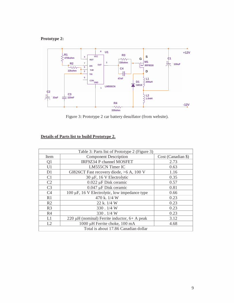
Figure 3: Prototype 2 car battery desulfator (from website).
Details of Parts list to build Prototype 2.
Table 3: Parts list of Prototype 2 (Figure 3) Item Component Description Cost (Canadian $) Q1 IRF9Z34 P channel MOSFET 2.73 U1 LM555CN Timer IC 0.63 D1 GI826CT Fast recovery diode, >6 A, 100 V 1.16 C1 30 µF, 16 V Electrolytic 0.35 C2 0.022 µF Disk ceramic 0.57 C3 0.047 µF Disk ceramic 0.81 C4 100 µF, 16 V Electrolytic, low impedance type 0.66 R1 470 k. 1/4 W 0.23 R2 22 k. 1/4 W 0.23 R3 330 . 1/4 W 0.23 R4 330 . 1/4 W 0.23 L1 220 µH (nominal) Ferrite inductor, 6+ A peak 3.12 L2 1000 µH Ferrite choke, 100 mA 4.68
Total is about 17.86 Canadian dollar
10
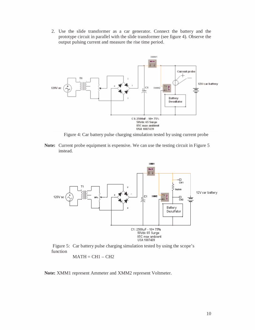
2. Use the slide transformer as a car generator. Connect the battery and the prototype circuit in parallel with the slide transformer (see figure 4). Observe the output pulsing current and measure the rise time period.
Figure 4: Car battery pulse charging simulation tested by using current probe Note: Current probe equipment is expensive. We can use the testing circuit in Figure 5
instead.
Figure 5: Car battery pulse charging simulation tested by using the scope’s function MATH = CH1 – CH2
Note: XMM1 represent Ammeter and XMM2 represent Voltmeter.
11
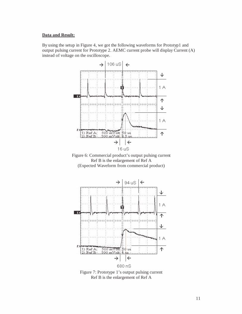
Data and Result: By using the setup in Figure 4, we got the following waveforms for Prototyp1 and output pulsing current for Prototype 2. AEMC current probe will display Current (A) instead of voltage on the oscilloscope.
Figure 6: Commercial product’s output pulsing current
Ref B is the enlargement of Ref A (Expected Waveform from commercial product)
Figure 7: Prototype 1’s output pulsing current
Ref B is the enlargement of Ref A
12
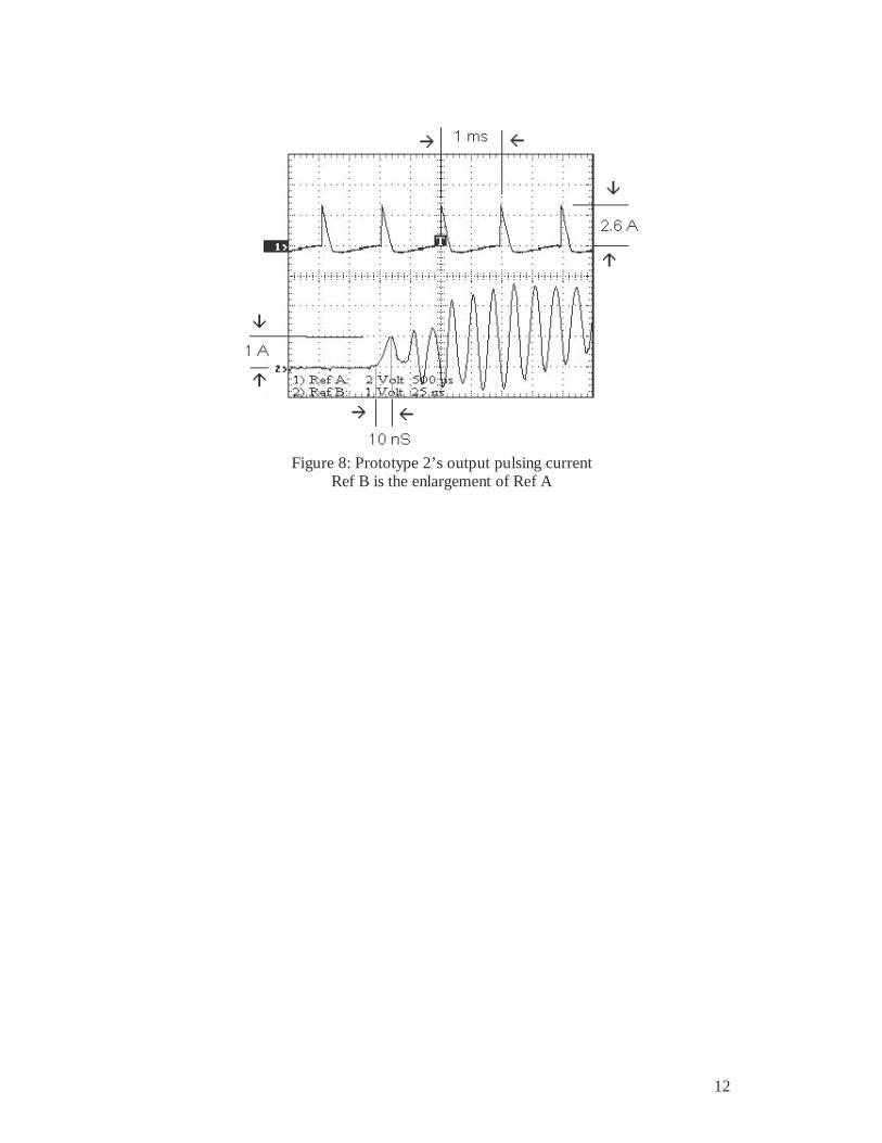
Figure 8: Prototype 2’s output pulsing current
Ref B is the enlargement of Ref A

13
Reasons of using the design of Prototype 1 instead of Prototype 2: As we described earlier in Technical Function part, we need an output pulsing current that equals to 1 Amp as most commercial products specified. The waveform in Figure 6 is our expected waveform from connecting the commercial product to the car battery using the setting as shown in Figure 4. From Figure 7, we can see Prototype 1’s output pulsing current amplitude is 1A and the rise time for the first pulse is only 680nS with 1A. Pulsing current amplitude drops constantly after the first pulse peak. Note: By adjusting the component R7, we have different output pulsing current
amplitude in Prototype 1. See Figure 2 at page 6 and more details in Table 2 at page 7.
From Figure 8, we can see Prototype 2 output pulsing current amplitude is 2.6A. The rise time for the first pulse is only 10nS with 1A. There are too many spikes after the first pulse peak. By studying the waveforms in Figure 6, Figure 7, and Figure 8, we decided to use Prototype 1 to do our final testing. It is because the output pulsing current in Prototype 1 is 1 Amp which is the same as what we expected from commercial products. The output pulsing current in Prototype 2 is 2.6A and has too many spikes after the first pulse peak. The current pulsing amplitude over 1A could vibrate down those crystal sulfate deposits on the plate to the bottom. Our goal is to de-solve the crystal sulfate deposits and to have more sulfuric acid returned to the battery solution, but not to break the crystal sulfate deposits down.
14
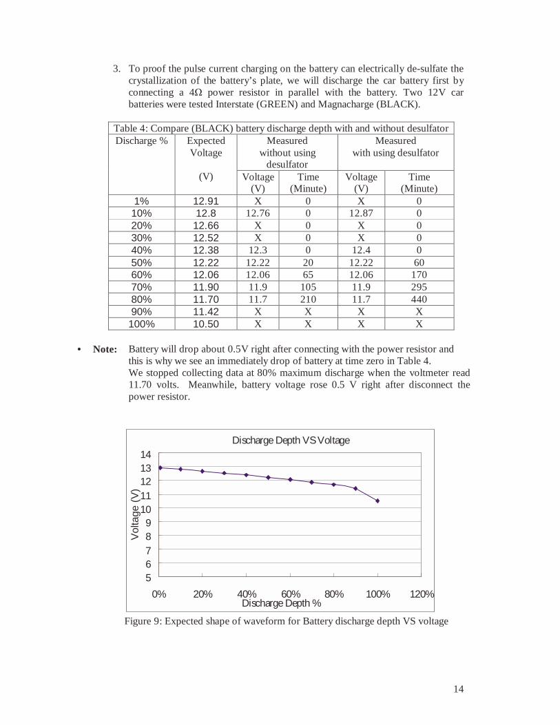
3. To proof the pulse current charging on the battery can electrically de-sulfate the crystallization of the battery’s plate, we will discharge the car battery first by connecting a 4Ω power resistor in parallel with the battery. Two 12V car batteries were tested Interstate (GREEN) and Magnacharge (BLACK).
Table 4: Compare (BLACK) battery discharge depth with and without desulfator
Measured without using
desulfator
Measured with using desulfator
Discharge % Expected Voltage
(V) Voltage
(V) Time
(Minute) Voltage
(V) Time
(Minute) 1% 12.91 X 0 X 0 10% 12.8 12.76 0 12.87 0 20% 12.66 X 0 X 0 30% 12.52 X 0 X 0 40% 12.38 12.3 0 12.4 0 50% 12.22 12.22 20 12.22 60 60% 12.06 12.06 65 12.06 170 70% 11.90 11.9 105 11.9 295 80% 11.70 11.7 210 11.7 440 90% 11.42 X X X X 100% 10.50 X X X X
• Note: Battery will drop about 0.5V right after connecting with the power resistor and
this is why we see an immediately drop of battery at time zero in Table 4. We stopped collecting data at 80% maximum discharge when the voltmeter read 11.70 volts. Meanwhile, battery voltage rose 0.5 V right after disconnect the power resistor.
Discharge Depth VS Voltage
56789
1011121314
0% 20% 40% 60% 80% 100% 120%Discharge Depth %
Vol
tage
(V
)
Figure 9: Expected shape of waveform for Battery discharge depth VS voltage

15
Discharging with and without using desulfator
0
20
65
105
210
0
60
170
295
440
0
0
0
00
1000
0
0
11.6
11.8
12
12.2
12.4
12.6
12.8
13
0 100 200 300 400 500 600 700 800 900 1000
Time (min)
Vol
tage
(V
)Discharging without using desulfator
Discharging with desulfator
Expected Dsicharging a good conditionbattery with desulfator
Figure 10: Discharging (BLACK) battery with and without using Prototype 1 desulfator
• Note: From the graph above, it proves that (BLACK) Battery with the use of Prototype
1 desulfator has longer discharging time than before. Current through Power Resistor Ir = V/R= 12/4 = 3A Measured = 2.88A Calculation for a perfect condition of a 12V car battery: Calculate (BLACK) battery capacity for 80% discharge: Assume (BLACK) battery is in good condition, we expect output 48AH (or 1000minutes) for 80% discharge. Expected: 80% x 60AH=48AH ; 48AH/2.88A = 16.66Hours = 1000 minutes Measured: Before using desulfator, (BLACK) battery has: 2.88A (210 minutes / 60min/hr) = 10.08AH. After using desulfator, (BLACK) battery has: 2.88A (440 minutes / 60min/hr) = 21.12AH
• Note: From Figure 10 we know that (BLACK) battery has not totally improved the sulfate problems due to the data that we measured (440minutes) and expected (1000minutes). The problem might be the battery is too old.
16
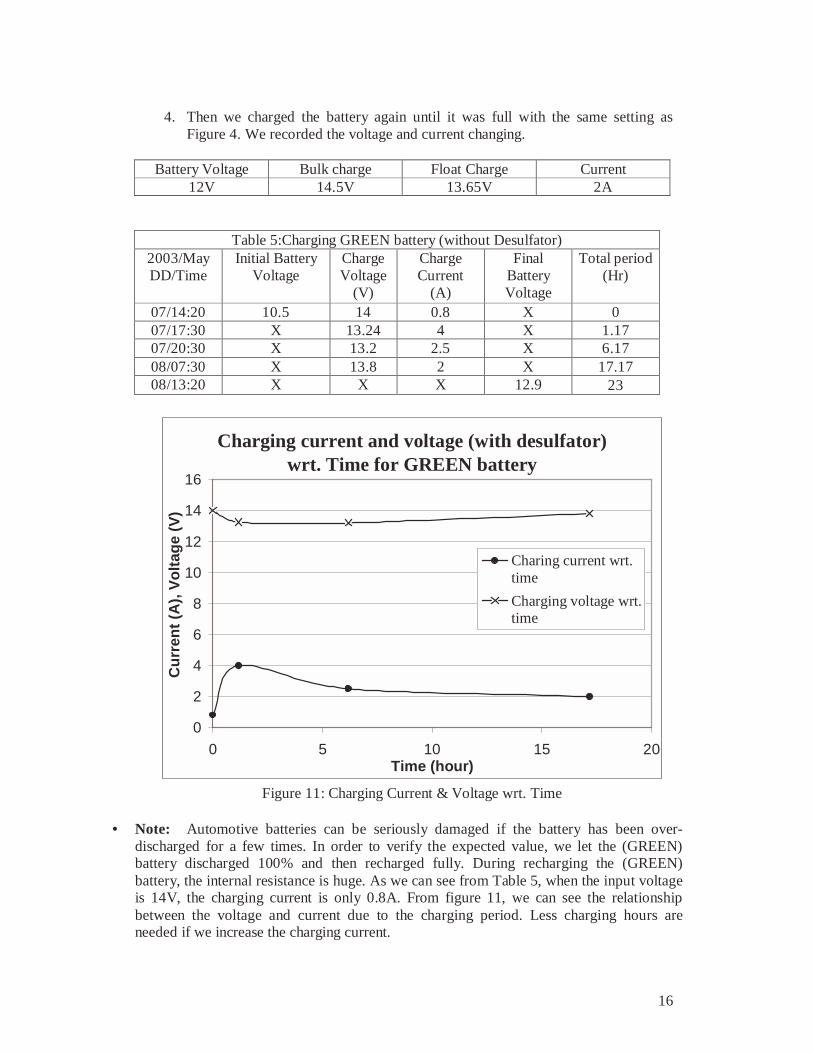
4. Then we charged the battery again until it was full with the same setting as
Figure 4. We recorded the voltage and current changing.
Battery Voltage Bulk charge Float Charge Current 12V 14.5V 13.65V 2A
Table 5:Charging GREEN battery (without Desulfator) 2003/May DD/Time
Initial Battery Voltage
Charge Voltage
(V)
Charge Current
(A)
Final Battery Voltage
Total period (Hr)
07/14:20 10.5 14 0.8 X 0 07/17:30 X 13.24 4 X 1.17 07/20:30 X 13.2 2.5 X 6.17 08/07:30 X 13.8 2 X 17.17 08/13:20 X X X 12.9 23
Charging current and voltage (with desulfator) wrt. Time for GREEN battery
0
2
4
6
8
10
12
14
16
0 5 10 15 20Time (hour)
Cu
rren
t (A
), V
olt
age
(V)
Charing current wrt.time
Charging voltage wrt.time
Figure 11: Charging Current & Voltage wrt. Time
• Note: Automotive batteries can be seriously damaged if the battery has been over-
discharged for a few times. In order to verify the expected value, we let the (GREEN) battery discharged 100% and then recharged fully. During recharging the (GREEN) battery, the internal resistance is huge. As we can see from Table 5, when the input voltage is 14V, the charging current is only 0.8A. From figure 11, we can see the relationship between the voltage and current due to the charging period. Less charging hours are needed if we increase the charging current.

17
Table 6: Charging BLACK battery (with Desulfator)
2003/May DD/Time
Initial Battery Voltage
Charging Voltage
(V)
Charging Current
(A)
Time (Hours)
Final Battery Voltage
11/16:50 11.70 V 14.7 1.97 0 X 11/17:50 X 14.7 1.58 1 X 11/18:55 X 14.7 1.57 2.08 X 11/20:40 X 14.7 1.19 3.83 X 12/09:40 X 14.7 0.75 16.83 X 12/17:50 X 14.7 0.62 24.17 12.68
Charging current (with desulfator) wrt. Time for BLACK battery
0
0.5
1
1.5
2
2.5
0 5 10 15 20 25 30
Time (Hour)
Cha
rgin
g C
urre
nt (
A)
Figure 12: Battery charging current characteristic
• Note: Due to the internal resistance, voltage and current will change while charging the battery. So we set the slide transformer output at 14.7 volts (constant) and
observe the relation between current and time. When battery is getting close to full charge, less current get through into the battery. We expect to see the charging period extend if the battery has been desulfates more times.

18
Conclusion: By generating a series of high amplitude current pulse (around 1 Amp) and charging it into the Lead acid battery from the battery desulfator used in conjunction (in parallel) with the conventional battery charger, we will are able to activate the large lead sulfate crystals on the cathode plate and improve the charging chemical relation efficiecy of the battery.
Therefore, having a battery desulfator hooked up in conjunction with car battery, every time when the engineer is turned, the battery desulfator starts functioning an the lead sulfate crystal size is reduced. More sulfuric acid is returned to the battery solution. The car battery will have a longer lifetime for use. In our project, we built two types of circuit, Prototype 1 and Prototype 2 (see Figure 2 at page 6 and Figure 3 at page8). In our final testing, we decided to use Prototype 1 instead of Prototype 2. It is because Prototype 1 gives a 1 Amp output pulsing current and Prototype 2 gives a 2.6 Amp output pulsing current. In 1 Amp output pulsing current, we are able to vibrate and de-solve the lead sulfate crystals. However, higher output pulsing current will result break down the lead sulfate crystals (see more explanation in page 12). In Prototype 1, we have replaced a 2k ohm resistor pot component called R7 (R7 was 120 ohm in commercial product) from the original commercial design. Therefore, by adjusting the component R7, we are able to adjust the output pulsing current amplitude in Prototype 1. As we see Table 4 at page 13 and Figure 10 at page 14, we see the discharging time almost doubled when a desulfator is connected. Although it is not as good as we predicted for a “perfect condition” of battery used in the testing, we can still say that the battery desulfator works.
19
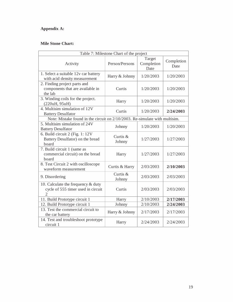
Appendix A: Mile Stone Chart:
Table 7: Milestone Chart of the project
Activity Person/Persons Target
Completion Date
Completion Date
1. Select a suitable 12v car battery with acid density measurement Harry & Johnny 1/20/2003 1/20/2003
2. Finding project parts and components that are available in the lab
Curtis 1/20/2003 1/20/2003
3. Winding coils for the project. (220uH, 95uH)
Harry 1/20/2003 1/20/2003
4. Multisim simulation of 12V Battery Desulfator
Curtis 1/20/2003 2/24/2003
Note: Mistake found in the circuit on 2/10/2003. Re-simulate with multisim. 5. Multisim simulation of 24V Battery Desulfator Johnny 1/20/2003 1/20/2003
6. Build circuit 2 (Fig. 1: 12V Battery Desulfator) on the bread board
Curtis & Johnny
1/27/2003 1/27/2003
7. Build circuit 1 (same as commercial circuit) on the bread board
Harry 1/27/2003 1/27/2003
8. Test Circuit 2 with oscilloscope waveform measurement
Curtis & Harry 2/03/2003 2/10/2003
9. Disordering Curtis & Johnny
2/03/2003 2/03/2003
10. Calculate the frequency & duty cycle of 555 timer used in circuit 2
Curtis 2/03/2003 2/03/2003
11. Build Prototype circuit 1 Harry 2/10/2003 2/17/2003 12. Build Prototype circuit 1 Johnny 2/10/2003 2/24/2003 13. Test the commercial circuit to
the car battery Harry & Johnny 2/17/2003 2/17/2003
14. Test and troubleshoot prototype circuit 1
Harry 2/24/2003 2/24/2003

20
15. Test and troubleshoot prototype
circuit 1 Johnny 2/24/2003 3/24/2003
16. Charge up the battery Harry 3/03/2003 3/03/2003 17. Draw the circuit 1 in multisim Curtis 3/03/2003 3/03/20033 18. Current Probe measurement on commercial product & circuit 1 to the new car battery
Curtis & Harry 3/03/2003 3/03/2003
Note: Prototype circuit 1 & commercial circuit are damaged due to the wrong connection setup of scope probes on 3/03/2003
19. Fix the commercial circuit Harry 3/03/2003 3/03/2003 20. Fix the prototype circuit 1 Harry 3/10/2003 3/10/2003 21. Draw the current probe testing circuit by multisim Curtis 3/24/2003 3/24/2003
22. Searching "car battery charge level wrt. Voltage" on the net Curtis 3/24/2003 3/24/2003
23. Test the prototype circuit 2 with car battery Johnny 3/31/2003 04/14/2003
24. Presentation All group Member 4/07/2003 4/07/2003
25. Wire the new core to improve the amplitude of current for circuit 1
Curtis 04/14/2003 04/14/2003
26. Build prototype circuit 1 as real product
Curtis 04/14/2003 04/14/2003
27. PIC programming for 7-segment display, pulse improvement with cold winding connection
Harry 04/14/2003 04/14/2003
28. Web search for modifying circuit 2
Johnny 04/14/2003 04/14/2003
29. Switching Power supply part 1 Harry 04/14/2003 04/14/2003 30. Real product circuit 1
troubleshooting Johnny 04/28/2003 Not finish
31. Troubleshooting Switching Power supply
Harry 04/28/2003 04/28/2003
32. Prepare for presentation (power point)
Curtis 04/28/2003 04/28/2003

21
33. Current Probe measurement
with working prototype circuit 1 (the current can be adjust by a resistor, R7)
Curtis & Harry 5/05/2003 5/05/2003
34. Finish the final report and prepare for presentation Curtis & Harry 5/05/2003 5/12/2003
35. Real product circuit 1 troubleshooting Harry 5/12/2003 5/12/2003

22
Appendix B: Reference: Magnacharge (Black) Battery: http://www.magnacharge.com/mchg_mcg.htm Magnacharge voltages vs. depth of discharge: http://www.magnacharge.com/mchg_all.htm#Battery%20Charging United States Patent And Trade Mark Office: http://patft.uspto.gov/netacgi/nph-Parser?Sect1=PTO1&Sect2=HITOFF&d=PALL&p=1&u=/netahtml/srchnum.htm&r=1&f=G&l=50&s1=6,184,650.WKU.&OS=PN/6,184,650&RS=PN/6,184,65 http://www.allegromicro.com/techpub2/cadex/index3311.htm http://uuhome.de/william.darden/carfaq9.htm yuasa-battery http://www.yuasa-battery.co.uk/Chargers.html Metals and Electrochemistry http://www.absolit.com/mc/emc7.htm Batterystuff.com http://www.4unique.com/battery/pulsetech/pulsetech.htm