basics of series ac circuits
DESCRIPTION
Basics of AC circuitsTRANSCRIPT
9/5/2014 EET 155 Unit 6: Series AC Circuits
http://people.sinclair.edu/nickreeder/eet155/mod06.htm 1/24
Unit 6: Series AC Circuits
In this unit we'll pull together a lot of things from earlier units and use them to analyze series circuits containing AC voltagesources. You'll need to remember what you've learned about AC fundamentals, capacitors, inductors, complex numbers, andphasors. Once you take all of that into account, though, you'll find that to analyze a series AC circuit, you follow the samesteps that you follow to analyze a series DC circuit.
Also, the same rules that hold for series DC circuits (such as Ohm's law, Kirchhoff's Voltage Law, and the Voltage-DividerRule) also hold for series AC circuits. But the math is a little more complicated, because each step involves phasors (complexnumbers) instead of ordinary numbers.
First, you should read the following sections of Thomas Floyd's Principles of Electric Circuits (8th edition):
Sinusoidal Response of Series RC Circuits (Section 15-2)Impedance of Series RC Circuits (Section 15-3)Analysis of Series RC Circuits (Section 15-4)Sinusoidal Response of Series RL Circuits (Section 16-1)Impedance of Series RL Circuits (Section 16-2)Analysis of Series RL Circuits (Section 16-3)Impedance of Series RLC Circuits (Section 17-1)Analysis of Series RLC Circuits (Section 17-2)
Then work through the e-Lesson and Self-Test questions below.
After you finish the e-Lesson, you'll be ready to take Quiz #6, perform Lab #6, and do Homework #6.
Units 4 and 5 Review
This unit will build on material that you studied in Unit 4 and Unit 5 . So let's begin by taking these two self-tests to

9/5/2014 EET 155 Unit 6: Series AC Circuits
http://people.sinclair.edu/nickreeder/eet155/mod06.htm 2/24
review what you learned in those units.
Review of Series DC Circuits
In EET 150 you learned how to analyze series DC circuits like the one shown below. Let's do a quick review of whatyou learned there.
You should recall that the basic steps in analyzing a circuit like this one are:1. Add the resistance values to find the circuit's total resistance, RT. For the circuit shown, this means that
RT = R1 + R2 + R3
2. Apply Ohm's law to the entire circuit to find the circuit's total current:
IT = VS ÷ RT
3. Recognize that, since we're dealing with a series circuit, each resistor's current is equal to the total current. For thecircuit shown:
I1 = I2 = I3 = IT
9/5/2014 EET 155 Unit 6: Series AC Circuits
http://people.sinclair.edu/nickreeder/eet155/mod06.htm 3/24
4. Apply Ohm's law to each resistor to find the voltage drops:
V1 = I1 × R1 and V2 = I2 × R2 and V3 = I3 × R3
Review: Kirchhoff's Voltage Law in Series DC Circuits
In EET 150 you also learned that Kirchhoff's Voltage Law (KVL) says that the sum of the voltage drops around anyclosed loop equals the sum of the voltage rises around that loop.In terms of a simple series DC circuit like the one you just analyzed, this means that the sum of all the resistor voltagedrops must equal the source voltage.
Review: Voltage Divider Rule in Series DC Circuits
In EET 150 you also learned that the voltage-divider rule is a shortcut rule that you can use to find the voltage dropacross a resistor in a series circuit.The rule says that the voltage across any resistance in a series circuit is equal to the ratio of that resistance to thecircuit's total resistance, multiplied by the source voltage.In equation form, this rule is expressed as:
Vx = VS×(Rx÷RT)
Review: Troubleshooting Series DC Circuits

9/5/2014 EET 155 Unit 6: Series AC Circuits
http://people.sinclair.edu/nickreeder/eet155/mod06.htm 4/24
Troubleshooting a non-working circuit means finding the problem that is preventing the circuit from workingcorrectly.The two most common types of problems are open circuits and short circuits.An open circuit, or "open," is a break in a circuit path.
The most important thing to remember about opens is that no current can flow through an open.Therefore, no current can flow anywhere in a series circuit containing an open.Since no current flows through an open, you can think of the open as having infinite resistance (R = ∞).Usually, an open will not have a voltage drop of 0 V. In fact, in a series DC circuit that contains an open, theentire source voltage will appear across the open, and no voltage will appear across any of the otherresistors.So if you measure the voltage between any two points in a series circuit containing an open, you'll measure 0 V ifthe two points are on the same side of the open, but you'll measure the entire source voltage if the points are onopposite sides of the open.
For example, suppose R3 is open in the circuit shown below. Then there will be 0 V across R1, across R2,and across R4. Also, Vab = 0 V. But there will be 9 V across R3. Also, Vac = 9 V, and Vbc = 9 V.
A short circuit, or "short," is a path of zero resistance connecting two points in a circuit that are not supposed to beconnected.
Since a short has zero resistance, the voltage across it must be zero. This follows from Ohm's law, V = I × R.A component is said to be short-circuited, or "shorted out," when there is a short circuit connected in parallel withit. No current flows through a short-circuited component. Instead, current is diverted through the short itself.
For example, suppose that in the circuit shown below there is a short between points a and b, perhapscaused by a loose wire clipping that connects these two points. Then R2 is short-circuited. No current will

9/5/2014 EET 155 Unit 6: Series AC Circuits
http://people.sinclair.edu/nickreeder/eet155/mod06.htm 5/24
flow through R2; instead, current will follow the path of zero resistance through the short itself (the wireclipping).
A short in a series DC circuit reduces the circuit's total resistance, causing more current to flow out of the voltagesource.
For example, in the circuit shown above, if R2 is short-circuited by a wire clipping that connects points aand b, then R2's resistance disappears from the circuit, and the circuit's total resistance is equal toR1 + R3 + R4.
That ends our quick review of series DC circuits. If you'd like a more thorough review, go to Unit 2 of EET 150. Nowlet's get back to AC circuits.
Sinusoidal Response of AC Circuits (Floyd, p. 610)
Here's an important point that we've mentioned a couple of times before and that is worth repeating: When a sinusoidalvoltage is applied to any circuit containing resistors, capacitors, and inductors, all of the circuit's currentwaveforms and voltage waveforms are sinusoids and have the same frequency as the source voltage.So, for example, if you're given the circuit shown below, and if you're told that the source voltage is a sinusoid having afrequency of 5 kHz, then you can say immediately that the current through every component is a 5-kHz sinusoidalcurrent, and the voltage drop across every component is a 5-kHz sinusoidal voltage.

9/5/2014 EET 155 Unit 6: Series AC Circuits
http://people.sinclair.edu/nickreeder/eet155/mod06.htm 6/24
Where things get a bit tricky is figuring out the peak values and phase shifts of these current and voltage waveforms.But we'll be able to do it, thanks to complex numbers.
Impedance (Floyd, p. 611)
Recall that resistance (R), capacitive reactance (XC), and inductive reactance (XL) are all measured in ohms.Each one of these quantities represents a component's opposition to the flow of AC current.Impedance is the general term that applies to all three of these quantities, or to a combination of them.
For example, if you combine a resistor and a capacitor in series, then their combined opposition to the flow of ACcurrent is called their total impedance. This total impedance is a combination of the resistor's resistance and thecapacitor's reactance.But you can't find total impedance simply by adding resistances and reactances together. For example, if you'vegot a 1-kΩ resistor in series with a capacitor whose reactance is 2 kΩ, their total impedance is not 3 kΩ. As we'llsee soon, you have to use complex numbers to find their total impedance.
The symbol for impedance is Z. It is measured in ohms.
Boldface Notation for Phasors (Floyd, p. 611)
Up to now we have used italicized, non-boldface letters to represent various quantities. In particular:R represents resistance.XC represents capacitive reactance.XL represents inductive reactance.Z represents impedance.V represents voltage.I represents current.

9/5/2014 EET 155 Unit 6: Series AC Circuits
http://people.sinclair.edu/nickreeder/eet155/mod06.htm 7/24
From this point onward, we will usually treat all of these quantities as phasors, which means we'll treat them ascomplex numbers with both a magnitude and an angle. We'll use the italic letters listed above to denote the magnitudeof the phasor, and we'll use boldface letters to represent the total phasor quantity (which includes both the magnitudeand the angle). In particular:
R represents a phasor resistance, which has both a magnitude (R) and an angle.XC represents a phasor capacitive reactance, which has both a magnitude (XC) and an angle.XL represents a phasor inductive reactance, which has both a magnitude (XL) and an angle.Z represents a phasor impedance, which has both a magnitude (Z) and an angle.V represents a phasor voltage, which has both a magnitude (V) and an angle.I represents a phasor current, which has both a magnitude (I) and an angle.
For example, suppose the total impedance in a circuit has a magnitude of 7.36 kΩ and an angle of 26.5°. At times wemight be interested in talking just about the magnitude, in which case we'll write
Z = 7.36 kΩ
At other times we might be interested in talking about the total phasor quantity (magnitude and angle), in which casewe'll write
Z = 7.36 Ð26.5° kΩ
Phasor Form of Resistance
We treat resistance as a phasor R whose magnitude R is the resistance in ohms and whose angle is 0°.We use 0° because voltage and current are in phase in resistors. (In other words, there is a 0° phase angle betweena resistor's current and its voltage.)
So in polar notation, the phasor form of resistance is
R = RÐ0°
We can easily convert this to rectangular notation, to get
R = R + j0
or simply
R = R

9/5/2014 EET 155 Unit 6: Series AC Circuits
http://people.sinclair.edu/nickreeder/eet155/mod06.htm 8/24
Thus, the phasor R for any resistor has a real part but no imaginary part. In the complex plane, resistance lies along thepositive real axis, as shown in the following diagram of a phasor representing a resistance of 50 Ω:
Phasor Form of Capacitive Reactance (Floyd, p. 611)
We treat capacitive reactance as a phasor XC whose magnitude XC is 1 ÷ (2pfC), and whose angle is −90°.We use −90° because voltage lags current by 90° in a capacitor.
So in polar notation, the phasor form of capacitive reactance is
XC = XC Ð−90°
We can easily convert this to rectangular notation, to get
9/5/2014 EET 155 Unit 6: Series AC Circuits
http://people.sinclair.edu/nickreeder/eet155/mod06.htm 9/24
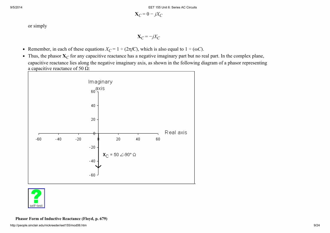
XC = 0 − jXC
or simply
XC = −jXC
Remember, in each of these equations XC = 1 ÷ (2pfC), which is also equal to 1 ÷ (ωC).Thus, the phasor XC for any capacitive reactance has a negative imaginary part but no real part. In the complex plane,capacitive reactance lies along the negative imaginary axis, as shown in the following diagram of a phasor representinga capacitive reactance of 50 Ω:
.
Phasor Form of Inductive Reactance (Floyd, p. 679)
9/5/2014 EET 155 Unit 6: Series AC Circuits
http://people.sinclair.edu/nickreeder/eet155/mod06.htm 10/24
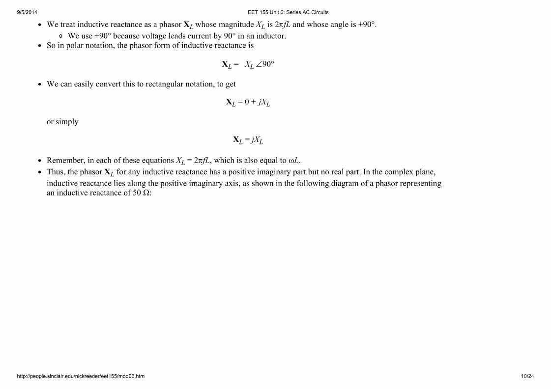
We treat inductive reactance as a phasor XL whose magnitude XL is 2pfL and whose angle is +90°.We use +90° because voltage leads current by 90° in an inductor.
So in polar notation, the phasor form of inductive reactance is
XL = XL Ð90°
We can easily convert this to rectangular notation, to get
XL = 0 + jXL
or simply
XL = jXL
Remember, in each of these equations XL = 2pfL, which is also equal to ωL.Thus, the phasor XL for any inductive reactance has a positive imaginary part but no real part. In the complex plane,inductive reactance lies along the positive imaginary axis, as shown in the following diagram of a phasor representingan inductive reactance of 50 Ω:

9/5/2014 EET 155 Unit 6: Series AC Circuits
http://people.sinclair.edu/nickreeder/eet155/mod06.htm 11/24
.
Phasor Form of Ohm's Law (Floyd, p. 614)
Once you know a component's resistance or reactance, you can use Ohm's law to find the component's current if youknows its voltage, or to find the component's voltage if you knows its current.To use Ohm's law in AC circuits, we'll treat voltages, currents, resistances, and reactances as phasors.For resistors, V = I × R.For capacitors, V = I × XC.For inductors, V = I × XL.Recall that impedance is the general term applied to resistance, capacitive reactance, inductive reactance, or anycombination of these. The symbol for impedance is Z, so we can write the most general form of Ohm's law as:

9/5/2014 EET 155 Unit 6: Series AC Circuits
http://people.sinclair.edu/nickreeder/eet155/mod06.htm 12/24
V = I × Z
Of course, you can also rearrange this equation (and the ones given above) to solve for current if you know voltage andimpedance, or to solve for impedance if you know current and voltage:
I = V ÷ Z
Z = V ÷ I
Remember, in each case, all quantities are phasors, not ordinary numbers.
Series Impedance (Floyd, p. 612)
Suppose we have a resistance in series with a reactance. We'd like to find the total impedance of these two components,but we can't simply add resistances and reactances as ordinary numbers. For example, a 1 kΩ resistance in series witha 2 kΩ capacitive reactance does not add up to 3 kΩ.Instead, we must add them as phasors. So, to find the total impedance of a 1 kΩ resistance in series with a 2 kΩcapacitive reactance, we must add 1Ð0° kΩ plus 2Ð−90° kΩ, which gives us a total of 2.24Ð−63.4° kΩ.It may seem strange that you can combine a 1 kΩ resistance with a 2 kΩ reactance and come up with a total of only2.24 kΩ, but that's how it works.
Analyzing Series AC Circuits
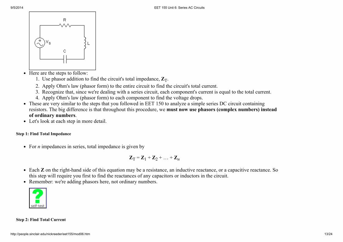
Now that you know how to treat resistances and reactances as phasors, and how to use the phasor form of Ohm's law,and how to use phasors to find total impedance, you're ready to analyze any series AC circuit, such as the series RLCcircuit shown below.
9/5/2014 EET 155 Unit 6: Series AC Circuits
http://people.sinclair.edu/nickreeder/eet155/mod06.htm 13/24
Here are the steps to follow:1. Use phasor addition to find the circuit's total impedance, ZT.2. Apply Ohm's law (phasor form) to the entire circuit to find the circuit's total current.3. Recognize that, since we're dealing with a series circuit, each component's current is equal to the total current.4. Apply Ohm's law (phasor form) to each component to find the voltage drops.
These are very similar to the steps that you followed in EET 150 to analyze a simple series DC circuit containingresistors. The big difference is that throughout this procedure, we must now use phasors (complex numbers) insteadof ordinary numbers.Let's look at each step in more detail.
Step 1: Find Total Impedance
For n impedances in series, total impedance is given by
ZT = Z1 + Z2 + … + Zn
Each Z on the right-hand side of this equation may be a resistance, an inductive reactance, or a capacitive reactance. Sothis step will require you first to find the reactances of any capacitors or inductors in the circuit.Remember: we're adding phasors here, not ordinary numbers.
Step 2: Find Total Current

9/5/2014 EET 155 Unit 6: Series AC Circuits
http://people.sinclair.edu/nickreeder/eet155/mod06.htm 14/24
Knowing the source voltage VS and the total impedance ZT, you can use Ohm's Law to find the current:
IT = VS ÷ ZT
Again, remember that we're dividing phasors, not ordinary numbers.
Step 3: Find Individual Currents
This step is the easiest. It simply requires you to remember that in any series circuit (DC or AC), every component'scurrent is equal to the total current:
IT = I1 = I2 = … = In
Step 4: Find Voltage Drops
Now that you know the current through each component, use Ohm's Law to find the voltage drop across eachcomponent:
V1 = I1 × Z1 and V2 = I2 × Z2 and V3 = I3 × Z3 and ...
Remember, Z1 is the first component's impedance, which will be a resistance if the first component is a resistor, or acapacitive reactance if the first component is a capacitor, or an inductive reactance if the first component is an inductor.Similarly for Z2, Z3, and so on for however many components the circuit contains.Again, remember that we're multiplying phasors, not ordinary numbers.

9/5/2014 EET 155 Unit 6: Series AC Circuits
http://people.sinclair.edu/nickreeder/eet155/mod06.htm 15/24
Phasor Diagrams
After you've analyzed a circuit by finding currents and voltage drops, you can draw a phasor diagram that shows ingraphical form how these quantities relate to each other. A phasor diagram simply shows each voltage and current as avector in the complex plane, drawn with the appropriate angle and magnitude.Here is a simple example showing the current and voltage phasors for a single component:
Here's another example showing the phasors for all voltages and currents in a particular series RC circuit.

9/5/2014 EET 155 Unit 6: Series AC Circuits
http://people.sinclair.edu/nickreeder/eet155/mod06.htm 16/24
From the diagram you can quickly see the relationship between the circuit's current and voltages.In every phasor diagram for a series circuit, you should find that the current and the resistor's voltage drop have thesame angle, since current and voltage in a resistor are always in phase with each other.Also, you should find that inductor voltage and capacitor voltage are always at a 90° angle to the current, whichshould make sense. (Remember ELI the ICEman from Unit 4?)
Kirchhoff's Voltage Law
As in DC circuits, Kirchhoff's Voltage Law (KVL) says that the sum of the voltage drops around any closed loopequals the sum of the voltage rises around that loop.

9/5/2014 EET 155 Unit 6: Series AC Circuits
http://people.sinclair.edu/nickreeder/eet155/mod06.htm 17/24
As we'll see in later units of this course, KVL applies to all circuits, whether series, parallel, or series-parallel.In this unit we're restricting our attention to series circuits containing a single voltage source. In these circuits,KVL simplifies to the following form: the source voltage in a series circuit is equal to the sum of the voltagedrops across the circuit's resistors, capacitors, and inductors.
Whenever you apply KVL to an AC circuit, you must use phasors, not ordinary numbers. If you just add themagnitudes of the voltages, instead of adding the magnitudes along with their angles, you won't get good results.
Voltage-Divider Rule
As in DC circuits, this is a shortcut rule for finding voltage drops in a series circuit.The voltage-divider rule says that the voltage Vx across any impedance Zx in a series circuit with source voltage VSis given by:
Vx = (Zx ÷ ZT) × VS
Again, use phasors, not ordinary numbers.
Troubleshooting Series AC Circuits
Above we reviewed the basics of troubleshooting series DC circuits. Almost all of these same points apply to series ACcircuits. (But there's one important difference noted below.) In particular:No current flows through an open.
Therefore, no current flows anywhere in a series circuit containing an open.Since no current flows through an open, you can think of the open as having infinite resistance (R = ∞).Usually, an open will not have a voltage drop of 0 V. In fact, in a series circuit that contains an open, the entire

9/5/2014 EET 155 Unit 6: Series AC Circuits
http://people.sinclair.edu/nickreeder/eet155/mod06.htm 18/24
source voltage will appear across the open, and no voltage will appear across any of the other resistors,capacitors, or inductors.So if you measure the voltage between any two points in a series circuit containing an open, you'll measure 0 V ifthe two points are on the same side of the open, but you'll measure the entire source voltage if the points are onopposite sides of the open.
A short has zero resistance and zero voltage.A component is said to be short-circuited, or "shorted out," when there is a short connected in parallel with it. Nocurrent flows through a short-circuited component. Instead, current is diverted through the short itself.
So far, everything we've said about opens and shorts in series AC circuits is the same as what we said earlier aboutopens and shorts in series DC circuits. But here's a difference:
A short in a series DC circuit will always reduce the circuit's total resistance, increasing the circuit's total current.But in a series AC circuit, a short could either increase or decrease the circuit's total impedance, and thereforecould either decrease or increase the total current.
Why is there this difference between shorts in DC and AC circuits? It's because of the difference between regularnumbers and complex numbers.
To find a series DC circuit's total resistance, you add two or more regular numbers. If one of the circuit's resistorsis shorted out, then you replace one of these numbers with zero, and this will decrease the total.
For example, suppose a series circuit contains a 100 Ω resistor, a 150 Ω resistor, and a 200 Ω resistor. Thenthe total resistance is 450 Ω. But if the 200 Ω resistor is shorted out, then you replace its resistance withzero, and so the total resistance decreases to 250 Ω. This decrease in total resistance will increase thecircuit's total current.
But to find a series AC circuit's total impedance, you add two or more complex numbers (phasors). If one of thecircuit's components is shorted out, then you replace one of these complex numbers with zero. When you'readding complex numbers, replacing one of them by zero could either decrease or increase the total.
For example, suppose a series AC circuit contains a 100Ð0° Ω resistance, a 150Ð90° Ω inductivereactance, and a 200Ð−90° Ω capacitive reactance. Then the total impedance is 112Ð−26.6° Ω. If thecapacitor is shorted out, then you replace its reactance with zero, and so the total impedance increases to180Ð56.3° Ω. This increase in total impedance will decrease the circuit's total current.On the other hand, suppose that in the same circuit the capacitor is okay and the resistor is shorted out.Then the circuit's total impedance is 50Ð−90° Ω, which is a decrease from the original total impedance.This decrease in total impedance will increase the circuit's total current.So a short in a series AC circuit may either increase or decrease the total impedance.

9/5/2014 EET 155 Unit 6: Series AC Circuits
http://people.sinclair.edu/nickreeder/eet155/mod06.htm 19/24
"Systems View" of a Circuit
In your electronics courses up to now, you've considered a circuit as a collection of individual components such asresistors, capacitors, and inductors. Most of the circuits you've studied have been very small, with just a fewcomponents.But real-world circuits are usually much more complex, with hundreds or even thousands of components. To study andanalyze such circuits, you have to shift your way of looking at circuits. Instead of concentrating on individualcomponents, it's more useful to think of the circuit as a system made up of parts that perform certain functions. The"parts" that I'm referring to here are not individual components. Rather, they are sub-circuits that contain manycomponents connected together to perform some function.For example, in your later courses you'll study amplifier circuits. These circuits contain transistors as well as resistors,capacitors, and inductors, so we're not ready to understand the details now. But there are a number of standard designsfor amplifier circuits, and rather than focusing on the details you might just want to consider the entire amplifier circuitas a "box." This box has two input terminals to which you can connect an input voltage, and two output terminals atwhich the amplifier's output voltage will appear. Here's a diagram:
The amplifier circuit contains many components (resistors, capacitors, transistors). But in this diagram we're notshowing those details.A more complete circuit might consist of an oscillator connected to an amplifier connected to a power amplifier, asshown here:

9/5/2014 EET 155 Unit 6: Series AC Circuits
http://people.sinclair.edu/nickreeder/eet155/mod06.htm 20/24
In this diagram we have three boxes representing three complicated sub-circuits. We're not showing the details of thesesub-circuits, but we are showing how the sub-circuits are connected to each other. (For example, the two lines betweenthe oscillator and the amplifier show that the oscillator's output voltage is also the amplifier's input voltage.)Next we'll look at a few simple series RC and RL circuits that can be thought of as "boxes" that perform a certainfunction.
Lag Circuits and Lead Circuits
In some applications, a designer needs to shift a voltage's phase angle by a certain amount. In such cases the designeruses a circuit that introduces a phase shift between the circuit's output voltage and its input voltage.There are two basic possibilities here. Either:
The circuit's output voltage lags its input voltage, in which case we're dealing with a lag circuit. Or:The circuit's output voltage leads its input voltage, in which case we're dealing with a lead circuit.
RC Lag Circuits and Lead Circuits (Floyd, pp. 620-623)
A simple series RC circuit can serve as either a lag circuit or a lead circuit, depending on whether you take the outputvoltage across the resistor or across the capacitor. In particular:
In any series RC circuit, the capacitor's voltage lags the source voltage, so you'll have a lag circuit if you take theoutput voltage across the capacitor, as shown here:

9/5/2014 EET 155 Unit 6: Series AC Circuits
http://people.sinclair.edu/nickreeder/eet155/mod06.htm 21/24
Also, in any series RC circuit, the resistor's voltage leads the source voltage, so you'll have a lead circuit if youtake the output voltage across the resistor, as shown here:
If you remember ELI the ICEman, you'll be able to quickly identify circuits like the ones above as either lead circuitsor lag circuits.
ICE reminds you that a capacitor's voltage tends to lag everything else in the circuit, so you've got a lag circuit ifyou're taking the output voltage across the capacitor.
Whenever you encounter circuits like these, you can always use the general techniques you learned above to analyze thecircuit and figure out how far the output voltage is shifted from the input voltage. Or you can remember the followingformulas.
For an RC lag circuit, the phase angle φ between the input and output is
φ = −tan−1(R ÷ XC)
For an RC lead circuit, the phase angle φ between the input and output is
φ = tan−1(XC ÷ R)
Using these formulas, and by choosing appropriate values of R and C, you can design a lead circuit or lag circuit to shift

9/5/2014 EET 155 Unit 6: Series AC Circuits
http://people.sinclair.edu/nickreeder/eet155/mod06.htm 22/24
the voltage by any desired angle.Here's a nice memory trick to help you remember those two formulas: Notice that the order of the R and the XC in eachformula is the same as the order of the resistor and the capacitor in the corresponding schematic diagram.
RL Lag Circuits and Lead Circuits (Floyd, pp. 685-689)
A simple series RL circuit can also serve as either a lag circuit or a lead circuit, depending on whether you take theoutput voltage across the resistor or across the inductor. In particular:
In any series RL circuit, the resistor's voltage lags the source voltage, so you'll have a lag circuit if you take theoutput voltage across the resistor, as shown here:
Also, in any series RL circuit, the inductor's voltage leads the source voltage, so you'll have a lead circuit if youtake the output voltage across the inductor, as shown here:
If you remember ELI the ICEman, you'll be able to quickly identify circuits like the ones above as either lead circuitsor lag circuits.

9/5/2014 EET 155 Unit 6: Series AC Circuits
http://people.sinclair.edu/nickreeder/eet155/mod06.htm 23/24
ELI reminds you that an inductor's voltage tends to lead everything else in the circuit, so you've got a lead circuitif you're taking the output voltage across the inductor.
Whenever you encounter circuits like these, you can always use the general techniques you learned above to analyze thecircuit and figure out how far the output voltage is shifted from the input voltage. Or you can remember the followingformulas.
For an RL lag circuit, the phase angle φ between the input and output is
φ = −tan−1(XL ÷ R)
For an RL lead circuit, the phase angle φ between the input and output is
φ = tan−1(R ÷ XL)
Here's a nice memory trick to help you remember those two formulas: Notice that the order of the R and the XL in eachformula is the same as the order of the resistor and the inductor in the corresponding schematic diagram.
Practice Problems
Want more practice analyzing series AC circuits? Here are a couple of learning objects that will generate as manypractice problems as you want, and then let you check your answers against the correct answers.The first one covers series RC circuits:
And the second one covers series RL circuits:

9/5/2014 EET 155 Unit 6: Series AC Circuits
http://people.sinclair.edu/nickreeder/eet155/mod06.htm 24/24
Unit 6 Review
This e-Lesson has covered several important topics, including:series AC circuitsphasor diagramsKirchhoff's Voltage Lawvoltage-divider ruletroubleshooting series AC circuitslag circuits and lead circuits.
To finish the e-Lesson, take this self-test to check your understanding of these topics.
Congratulations! You've completed the e-Lesson for this unit. What's next?
Take Online Quiz #6.Perform Lab #6 and turn in a typed short lab report. (You may wish to review my instructions on writing shortreports.)Do Homework #6.Keep practicing your skills by playing the games on the Games page.Prepare for Unit 7 by reading Sections 15-5, 15-6, 16-4, 16-5, 17-4, and 17-5 of Thomas Floyd's Principles of ElectricCircuits (8th edition).
Then you'll be ready to go on to Unit 7 .
Nick Reeder | Electronics Engineering Technology | Sinclair Community College
Send comments to [email protected]