basics of computer network
TRANSCRIPT
For more Https://www.ThesisScientist.com
Unit 1
1.1 What is a computer network?
Computer network is a distributed system consisting of loosely coupled computers and other
devices. Any two of these devices, which we will from now on refer to as network elements or
transmitting elements, can communicate with each other through a communication medium. In
order for these connected devices to be considered a communicating network, there must be a set
of communicating rules or protocols each device in the network must follow to communicate wit
another device in the network. The resulting combination consisting of hardware and software is
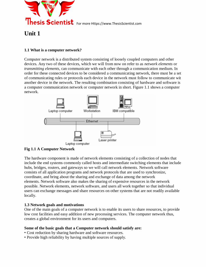
a computer communication network or computer network in short. Figure 1.1 shows a computer
network.
Fig 1.1 A Computer Network
The hardware component is made of network elements consisting of a collection of nodes that
include the end systems commonly called hosts and intermediate switching elements that include
hubs, bridges, routers, and gateways so we will call network elements. Network software
consists of all application programs and network protocols that are used to synchronize,
coordinate, and bring about the sharing and exchange of data among the network
elements. Network software also makes the sharing of expensive resources in the network
possible. Network elements, network software, and users all work together so that individual
users can exchange messages and share resources on other systems that are not readily available
locally.
1.3 Network goals and motivations
One of the main goals of a computer network is to enable its users to share resources, to provide
low cost facilities and easy addition of new processing services. The computer network thus,
creates a global environment for its users and computers.
Some of the basic goals that a Computer network should satisfy are:
• Cost reduction by sharing hardware and software resources.
• Provide high reliability by having multiple sources of supply.

For more Https://www.ThesisScientist.com
• Provide an efficient means of transport for large volumes of data among various locations
(High throughput).
• Provide inter-process communication among users and processors.
• Reduction in delay driving data transport.
• Increase productivity by making it easier to share data amongst users.
• Repairs, upgrades, expansions, and changes to the network should be performed with
minimal impact on the majority of network users.
• Standards and protocols should be supported to allow many types of equipment from
different vendors to share the network (Interpretability).
• Provide centralized/distributed management and allocation of network resources like host
processors, transmission facilities etc.
1.4 Computer Network Models
There are several configuration models that form a computer network. The most common of
these are the centralized and distributed models.
1.4.1 Centralized model: It consists of several computers and devices are interconnected, and
can talk to each other. However, there is only one central computer, called the master, through
which all correspondence must take place. Dependent computers, called surrogates, may have
reduced local resources, such as memory, and sharable global resources are controlled by the
master at the center.As shown in fig 1.2
Fig 1.2 A Centralized Network
Model
1.4.2 Distributed model: It consists of loosely coupled computers interconnected by a
communication network consisting of connecting elements and communication channels. The
computers themselves may own their resources locally or may request resources from a remote
computer. These computers are known by a string of names, including host, client, or node. If a
host has resources that other hosts need, then that host is known as a server. Communication and
sharing of resources are not controlled by the central computer but are arranged between any two
communicating elements in the network. As shown in fig 1.3
Fig 1.3 A Distributed Network Model

For more Https://www.ThesisScientist.com
1.5 Classification of networks
Depending on the transmission technology i.e., whether the network contains switching elements
or not, we have two types of networks:
• Broadcast networks.
• Point-to-point or Switched networks.
1.5.1 Broadcast Networks
Broadcast networks have a single communication channel that is shared by all the machines on
the network. In this type of network, short messages sent by any machine are received by all the
machines on the network. The packet contains an address field, which specifies for whom the
packet is intended. All the machines, upon receiving a packet check for the address field, if the
packet is intended for itself, it processes it and if not the packet is just ignored.
Using Broadcast networks, we can generally address a packet to all destinations (machines) by
using a special code in the address field. Such packets are received and processed by all machine
on the network. This mode of operation is known as “Broadcasting”.
Some Broadcast networks also support transmission to a subset of machines and this is known
as “Multicasting”. One possible way to achieve Multicasting is to reserve one bit to indicate
multicasting and the remaining (n-1) address bits contain group number. Each machine can
subscribe to any or all of the groups. Broadcast networks are easily configured for
geographically localized networks.
Broadcast networks may be Static or dynamic, depending on how the channel is allocated.
� In Static allocation, time is divided into discrete intervals and using round robin method,
each machine is allowed to broadcast only when its time slot comes up. This method is
inefficient because the channel capacity is wasted when a machine has nothing to broadcast
during its allocated slot.
� Dynamic allocation may be centralized or decentralized. In centralized allocation method,
there is a single entity, for example, a bus arbitration unit which determines who goes next
and this is achieved by using some internal algorithm. In Decentralized channel allocation
method, there is no central entity, here each machine decides for itself whether or not to
transmit.

For more Https://www.ThesisScientist.com
The different types of Broadcast networks are:
• Packet Radio Networks.
• Satellite Networks.
• Local Area Networks.
1.5.2 Point-to-Point or Switched Networks
Point–to-point or switched, networks are those in which there are many connections between
individual pairs of machines. In these networks, when a packet travels from source to destination
it may have to first visit one or more intermediate machines. Routing algorithms play an
important role in Point-to-point or Switched networks because often multiple routes of different
lengths are available. An example of switched network is the international dial-up telephone
system.
The different types of Point- to-point or Switched networks are:
• Circuit Switched Networks.
• Packet Switched Networks.
1.6 Computer Network Types
Computer Networks are mostly classified on the basis of the geographical area that the network
covers, the topology used, the transmission media used and the computing model used.
Based on the geographical area covered the networks may be LAN, MAN, WAN.
1.6.1 MAN (Metropolitan Area Network): Metropolitan Area Network is a Computer network
designed for a town or city as shown in fig 1.4. In terms of geographic area MAN’s are larger
than
local-area networks (LANs), but smaller than wide-area networks (WANs). MAN’s are usually
characterised by very high-speed connections using fiber optical cable or other digital media.
The Typical Characteristics of a MAN are:
• Confined to a larger area than a LAN and can range from 10km to a few 100km in length.
• Slower than a LAN but faster than a WAN.
• Operates at a speed of 1.5 to 150 Mbps.
• Expensive equipment.
• Moderate error rates.

For more Https://www.ThesisScientist.com
Fig 1.4 Metropolitan Area Network
1.6.2 WAN (Wide Area Network): Wide Area Network is a computer network that spans a
relatively large geographical area. Typically, a WAN consists of two or more local area networks
(LANs), which are depicted, in Fig 1.5 and Fig 1.6. They can connect networks across cities,
states or even countries. Computers connected to a wide-area network are often connected
through public networks, such as the telephone system. They can also be connected through
leased lines or satellites.
The Typical characteristics of a WAN are:
• A WAN can range from 100km to 1000km and the speed between cities can vary form1.5
Mbps to 2.4 Gbps.
• WAN supports large number of computers and multiple host machines.
• Various segments of network are interconnected using sophisticated support devices like
routers and gateways.
• Usually the speed is much slower than LAN speed.
• Highest possible error rate compared to LAN & MAN.

For more Https://www.ThesisScientist.com
Fig 1.5 WAN Networks
1.6.3 LAN (Local Area Network)
Local Area Network is a computer network that spans over a relatively small area.Most LANs
are confined to a single building or group of buildings within a campus.However, one LAN can
be connected to other LANs over any distance via telephone lines and radio waves. A system of
LANs connected in this way is called a wide-area network (WAN).Most LANs connect
workstations and personal computers. Each node (individual computer) in a LAN has its own
CPU with which it executes programs, but it is also able to access data and devices anywhere on
the LAN. This means that many users can share data as well as expensive devices, such as laser
printers, fax machines etc.Users can also use the LAN to communicate with each other, by
sending e-mail or engaging in chat sessions. There are many different types of LANs, Ethernets
being the most common for PCs.
The following characteristics differentiate one LAN from another:
• Topology: The geometric arrangement of devices on the network. For example, devices
can be arranged in a ring or in a straight line.
• Protocols: The rules and encoding specifications for sending data. The protocols also
determine whether the network uses peer-to-peer or client/server architecture.
• Media: Devices can be connected by twisted-pair wire, coaxial cables, or fiber optic
cables. Some networks communicate via radio waves hence; do not use any connecting
media.
LANs are capable of transmitting data at very fast rates, much faster than data can be transmitted
over a telephone line; but the distances are limited, and there is also a limit on the number of
computers that can be attached to a single LAN.

For more Https://www.ThesisScientist.com
The typical characteristics of a LAN are:
• Confined to small areas i.e., it connects several devices over a distance of 5 to 10 km.
• High speed.
• Most inexpensive equipment.
• Low error rates.
• Data and hardware sharing between users owned by the user.
• Operates at speeds ranging from 10Mbps to 100Mbps. Now days 1000 Mbps are available.
Fig 1.7 of LAN
Network
1.7. Network topology
Topology refers to the shape of a network, or the network’s layout. How different nodes in a
network are connected to each other and how they communicate with each other is determined
by the network's topology. Topologies are either physical or logical.
Some of the most common network topologies are:
• Bus topology
• Star topology
• Ring topology
• Tree topology
• Mesh topology
• Cellular topology.
• Hybrid topology.
1.7.1 Bus Topology
In Bus topology, all devices are connected to a central cable, called the bus or backbone. The bus
topology connects workstations using a single cable. Each workstation is connected to the next

For more Https://www.ThesisScientist.com
workstation in a point-to-point fashion. All workstations connect to the same cable. Fig
1.8shows
computers connected using Bus Topology. In this type of topology, if one workstation goes
faulty all workstations may be affected as all workstations share the same cable for the sending
and receiving of information. The cabling cost of bus systems is the least of all the different
topologies. Each end of the cable is terminated using a special terminator. The common
implementation of this topology is Ethernet. Here, message transmitted by one workstation is
heard by all the other workstations.
Advantages of Bus Topology
• Installation is easy and cheap when compared to other topologies.
• Connections are simple and this topology is easy to use.
• Less cabling is required.
Disadvantages of Bus Topology
• Used only in comparatively small networks.
• As all computers share the same bus, the performance of the network deteriorates when we
increase the number of computers beyond a certain limit.
• Fault identification is difficult.
• A single fault in the cable stops all transmission.
1.7.2 Star Topology
Star topology uses a central hub through which, all components are connected. In a Star
topology, the central hub is the host computer, and at the end of each connection is a terminal as
shown in Fig 1.9. Nodes communicate across the network by passing data through the hub. A
star network uses a significant amount of cable as each terminal is wired back to the central hub,
even if two terminals are side by side but several hundred meters away from the host. The central
hub makes all routing decisions, and all other workstations can be simple. An advantage of the
star topology is, that failure, in one of the terminals does not affect any other terminal; however,
failure of the central hub affects all terminals. This type of topology is frequently used to connect
terminals to a large time-sharing host computer.
Advantages of Star Topology
• Installation and configuration of network is easy.
• Less expensive when compared to mesh topology.
• Faults in the network can be easily traced.
• Expansion and modification of star network is easy.
• Single computer failure does not affect the network.
• Supports multiple cable types like shielded twisted pair cable, unshielded twisted pair

For more Https://www.ThesisScientist.com
cable, ordinary telephone cable etc.
Disadvantages of Star Topology
• Failure in the central hub brings the entire network to a halt.
• More cabling is required in comparison to tree or bus topology because each node is
connected to the central hub.
Fig 1.9 Star topology
1.7.3 Ring Topology
In Ring Topology all devices are connected to one another in the shape of a closed loop, so that
each device is connected directly to two other devices, one on either side of it, i.e., the ring
topology connects workstations in a closed loop, which is depicted in Fig 1.10. Each terminal is
connected to two other terminals (the next and the previous), with the last terminal being
connected to the first. Data is transmitted around the ring in one direction only; each station
passing on the data to the next station till it reaches its destination. Information travels around the
ring from one workstation to the next. Each packet of data sent on the ring is prefixed by the
address of the station to which it is being sent. When a packet of data arrives, the workstation
checks to see if the packet address is the same as its own, if it is, it grabs the data in the packet. If
the packet does not belong to it, it sends the packet to the next workstation in the ring. Faulty
workstations can be isolated from the ring. When the workstation is powered on, it connects
itself to the ring. When power is off, it disconnects itself from the ring and allows the
information to bypass the workstation.
The common implementation of this topology is token ring. A break in the ring causes the entire
network to fail. Individual workstations can be isolated from the ring.
Advantages of Ring Topology
• Easy to install and modify the network.
• Fault isolation is simplified.
• Unlike Bus topology, there is no signal loss in Ring topology because the tokens are data
packets that are re-generated at each node.
Disadvantages of Ring Topology
• Adding or removing computers disrupts the entire network.
• A break in the ring can stop the transmission in the entire network.

For more Https://www.ThesisScientist.com
• Finding fault is difficult.
• Expensive when compared to other topologies.
Fig 1.10 Ring topology
1.7.4 Tree Topology
Tree topology is a LAN topology in which only one route exists between any two nodes on the
network. The pattern of connection resembles a tree in which all branches spring from one root.
Fig 1.11 shows computers connected using Tree Topology. Tree topology is a hybrid topology, it
is similar to the star topology but the nodes are connected to the secondary hub, which in turn is
connected to the central hub. In this topology groups of star-configured networks are connected
to a linear bus backbone.
Advantages of Tree Topology
• Installation and configuration of network is easy.
• Less expensive when compared to mesh topology.
• Faults in the network can be detected traced.
• The addition of the secondary hub allows more devices to be attached to the central hub.
• Supports multiple cable types like shielded twisted pair cable, unshielded twisted pair
cable, ordinary telephone cable etc.
Disadvantages of Tree Topology
• Failure in the central hub brings the entire network to a halt.
• More cabling is required when compared to bus topology because each node is connected
to the central hub.
Fig 1.11 Tree topology
For more Https://www.ThesisScientist.com
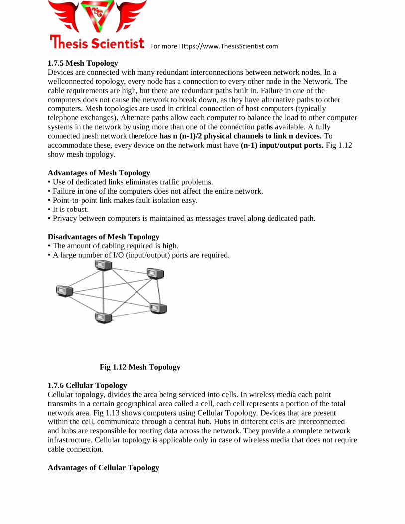
1.7.5 Mesh Topology
Devices are connected with many redundant interconnections between network nodes. In a
wellconnected topology, every node has a connection to every other node in the Network. The
cable requirements are high, but there are redundant paths built in. Failure in one of the
computers does not cause the network to break down, as they have alternative paths to other
computers. Mesh topologies are used in critical connection of host computers (typically
telephone exchanges). Alternate paths allow each computer to balance the load to other computer
systems in the network by using more than one of the connection paths available. A fully
connected mesh network therefore has n (n-1)/2 physical channels to link n devices. To
accommodate these, every device on the network must have (n-1) input/output ports. Fig 1.12
show mesh topology.
Advantages of Mesh Topology
• Use of dedicated links eliminates traffic problems.
• Failure in one of the computers does not affect the entire network.
• Point-to-point link makes fault isolation easy.
• It is robust.
• Privacy between computers is maintained as messages travel along dedicated path.
Disadvantages of Mesh Topology
• The amount of cabling required is high.
• A large number of I/O (input/output) ports are required.
Fig 1.12 Mesh Topology
1.7.6 Cellular Topology
Cellular topology, divides the area being serviced into cells. In wireless media each point
transmits in a certain geographical area called a cell, each cell represents a portion of the total
network area. Fig 1.13 shows computers using Cellular Topology. Devices that are present
within the cell, communicate through a central hub. Hubs in different cells are interconnected
and hubs are responsible for routing data across the network. They provide a complete network
infrastructure. Cellular topology is applicable only in case of wireless media that does not require
cable connection.
Advantages of Cellular Topology

For more Https://www.ThesisScientist.com
• If the hubs maintain a point-to-point link with devices, trouble shooting is easy.
• Hub-to-hub fault tracking is more complicated, but allows simple fault isolation.
Disadvantages of Cellular Topology
• When a hub fails, all devices serviced by the hub lose service (are affected).
Fig 1.13 Cellular topology
1.8 Applications of network
Computer networks are used as a highly reliable medium for exchange of information. Using a
computer network we can do virtually everything that a Mainframe or a Minicomputer can do,
but at a much lower cost. There are numerous applications of computer networks some of them
are:
• Share resources and information.
• Access to remote information.
• Person-to-person communication.
• Interactive entertainment.
1.8.1 Share Resources and Information
Using a Computer network we can share expensive resources such as laser printers, CD-ROM
Drives, Fax machines etc. We can share information and many persons can work together on
projects and tasks that require co-ordination and communication, even though these users may
not be physically close.
1.8.2 Access to Remote Information
Access to remote information involves interaction between a person and a remote database.
Financial Institutions allow access to their information so that people can pay their bills, handle
their investments and manage their bank accounts electronically. Online shopping also allows
people, access to product information before purchasing the product.
These days, many newspapers and digital libraries are available online and allow users to
access news and information which is of interest to them. Another application is the
World Wide Web, which contains information about a wide variety of subjects like health,
sports, science, recreation, history, government etc.
1.8.3 Person-to-person Communication

For more Https://www.ThesisScientist.com
Person-to-person communication is mostly carried out using e-mail (Electronic mail)
Electronic mail is a simple, yet potent facility. E-mail is more valuable and useful than the
telephone because by using e-mail we can convey information that is difficult or impossible to
read over the telephone, like reports, tables, charts, images etc.
Using a computer network, it is also possible to organise virtual meeting among people who
are far away from each other and this is called video conferencing. Virtual meetings have other
applications such as in Distance education, getting medical opinions from distant specialists
(remote diagnosis) etc. Multimedia communication can also be used for tele training.
1.8.4 Interactive Entertainment
Computer Networks such as Internet offer a wide variety of entertainment; there are many
companies online, which offer video-on-demand. A large variety of militiperson real-time
simulation games, like hide-and seek in a virtual dungeon and flight simulators with the players
in one team trying to shoot down the players in the opposite team and many such games are
available on-line.
1.9 Network architecture
Depending on the architecture used Networks can be classified as Client/Server or Peer-to-Peer
Networks.
1.9.1 Client/Server Architecture
Client/Server Architecture is one in which the client (personal computer or workstation) is the
requesting machine and the server is the supplying machine, both of which are connected via a
local area network (LAN) or wide area network (WAN). A client/server network is called
Centralised or Server based network. Fig 1.15 shows the arrangement of computers in the
client/server environment. The client contains the user interface and may perform some or all of
the application processing. Servers can be high-speed microcomputers, minicomputers or even
mainframes. A database serve maintains the databases and processes requests from the client to
extract data from or update the database. An application server provides additional business
processing for the clients. The term client/server is sometimes used to contrast a peer-to-peer
network, in which any client can also act as a server. In that case, a client/server entails having a
dedicated server.
For more Https://www.ThesisScientist.com
Fig 1.15 client /server architecture
Type of client /server architecture are:-
1.9.1.1 Non-client/server
In non-client/server architecture, the server is nothing more than a remote disk drive.
The user’s machine does all the processing. If, many users routinely perform lengthy searches,
this can bog down the network, because each client has to pass the entire database over the net.
At 1,000 bytes per record, a 10,000 record database requires 10MB of data be transmitted.
1.9.1.2 Two-tier client/server
Two-tier client/server is really the foundation of client/server. The database processing is done
in the server. An SQL request is generated in the client and transmitted to the server. The
DBMS searches locally and returns only matching records. If 50 records met the criteria, only
50K would be transmitted. This reduces traffic in the LAN.
1.9.1.3 Three-tier client/server
Many applications lend themselves to centralised processing. If, they contain proprietary
algorithms, security is improved. Upgrading is also simpler. Sometimes, programs are just too
demanding to be placed into every client PC. In three-tier client/server, application processing
is performed in one or more servers.
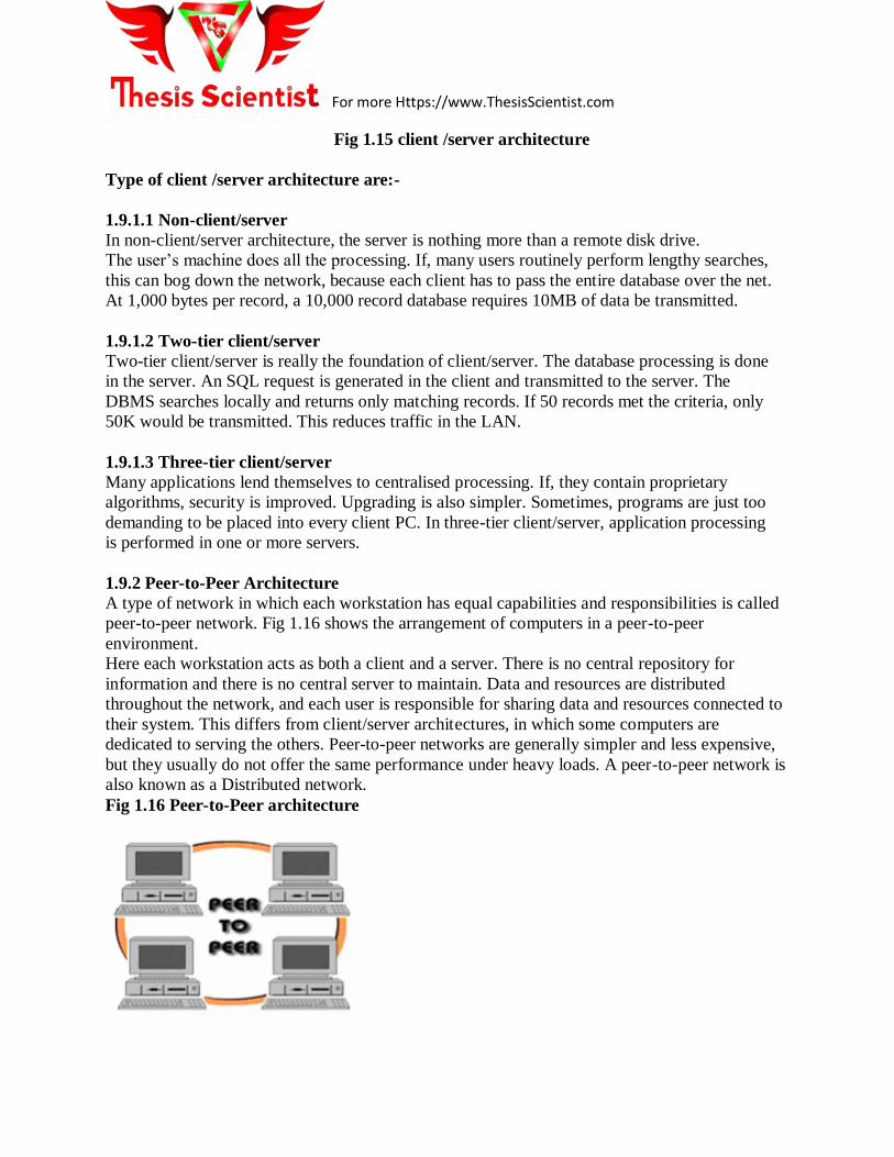
1.9.2 Peer-to-Peer Architecture
A type of network in which each workstation has equal capabilities and responsibilities is called
peer-to-peer network. Fig 1.16 shows the arrangement of computers in a peer-to-peer
environment.
Here each workstation acts as both a client and a server. There is no central repository for
information and there is no central server to maintain. Data and resources are distributed
throughout the network, and each user is responsible for sharing data and resources connected to
their system. This differs from client/server architectures, in which some computers are
dedicated to serving the others. Peer-to-peer networks are generally simpler and less expensive,
but they usually do not offer the same performance under heavy loads. A peer-to-peer network is
also known as a Distributed network.
Fig 1.16 Peer-to-Peer architecture

For more Https://www.ThesisScientist.com
1.10 Network Criteria
A network must be able to meet a certain number of criteria. The most important of these are
performance, reliability, and security.
1.10.1 Performance
Performance can be measured in many ways, including transit time and response time.
Transit time is the amount of time required for a message to travel from one device to another.
Response time is the elapsed time between an inquiry and a response. The performance of a
network depends on a number of factors, including the number of users, the type of transmission
medium, the capabilities of the connected hardware, and the efficiency of the software.
Performance is often evaluated by two networking metrics: throughput and delay. We often
need more throughput and less delay. However, these two criteria are often contradictory. If we
try to send more data to the network, we may increase throughput but we increase the delay
because of traffic congestion in the network.
1.10.2 Reliability
In addition to accuracy of delivery, network reliability is measured by the frequency of failure,
the time it takes a link to recover from a failure, and the network's robustness in a catastrophe.
1.10.3 Security
Network security issues include protecting data from unauthorized access, protecting data from
damage and development, and implementing policies and procedures for recovery from breaches
and data losses.
1.11 Advantages of networks
Computers in a networked environment provide numerous advantages when compared to
computers in a stand alone environment. The immense benefits that the computer networks
provide are in the form of excellent sharing of computational resources, computational load, and
increased level of reliability, economy and efficient person-to-person communication.
Following are some of the major advantages of using computer networks.
1.11.1 Resource Sharing: The main aim of a computer network is to make all programs,
equipment, and data available to anyone on the network without regard to the physical location
of the resource and the user. Users need to share resources other than files, as well. A common
example being printers. Printers are utilised only a small percentage of the time; therefore,
companies don’t want to invest in a printer for each computer. Networks can be used in this
situation to allow all the users to have access to any of the available printers.
1.11.2 High Reliability: Computer networks provide high reliability by having alternative
sources of supply. For example, all files could be replicated on two or three machines, so, if one
of them is unavailable (due to hardware failure), the other copies could be used. In addition, the
presence of multiple CPUs means that if one goes down, the others may be able to take over its
work, although at reduced performance. For military, banking, air traffic control, nuclear reactor

For more Https://www.ThesisScientist.com
safety, and many other applications, the ability to continue operating in the face of hardware
problems is of utmost importance.
1.11.3 Saving Money: Small computers have a much better price/performance ratio than larger
ones. Mainframes are roughly a factor of ten faster than personal computers but they cost much
more. This imbalance has caused many systems designers to build systems consisting of personal
computers, one per user, with data kept on one or more shared file server machines. In this
model, the users are called clients, and the whole arrangement is called the client-server model.
Scalability: The ability to increase the system performance gradually as the workload grows just
by adding more processors. With centralized mainframes, when a system is full, it must be
replaced by a larger one, usually at great expense and even greater disruption to the users. With
client-server model, new clients and new servers can be added when needed.
1.11.4 Communication Medium: A computer network can provide a powerful communication
medium among widely separated users. Using a computer network it is easy for two or more
people who are working on the same project and who live far apart to write a report together.
When one worker, makes a change to an on-line document, the others can see the change
immediately, instead of waiting several days for a letter. Such a speedup makes cooperation
among far-flung groups of people easy whereas previously it was impossible.
1.11.5 Increased Productivity: Networks increase productivity as several people can enter data
at the same time, but they can also evaluate and process the shared data. So, one person can
handle accounts receivable, and someone else processes the profit-and-loss statements
1.12 Network Services
For a communication network to work effectively, data in the network must be able to move
from one network element to another. This can only happen if the network services to move such
data work. For data networks, these services fall into two categories:
• Connection services to facilitate the exchange of data between the two network
communicating end-systems with as little data loss as possible and in as little time as
possible
• Switching services to facilitate the movement of data from host to host across the length
and width of the network mesh of hosts, hubs, bridges, routers, and gateways
1.12.1 Connection Services
How do we get the network transmitting elements to exchange data over the network?
Two types of connection services are used: the connected-oriented and connectionless
services.
1.12.1.1 Connected-Oriented Services
In a connection-oriented service, a connection is first established between the sender and the
receiver. Data are transferred. At the end, the connection is released. Eg three-way handshake.
Connection-oriented transmission has three stages. These are:
(i) Connection establishment: In connection oriented services, before transmitting data, the
For more Https://www.ThesisScientist.com
sending device must first determine the availability of the other to exchange data and a
connection must be established by which data can be sent. Connection establishment requires
three steps.
These are:
a) First the sender computer requests the connection by sending a connection request packet to
the intended receiver.
(b) Then the receiver computer returns a confirmation packet to the requesting computer.
(c) Finally, the sender computer returns a packet acknowledging the confirmation.
(ii) Data transfer: After the connection gets established, the sender starts sending data packets
to the receiver.
(iii) Connection termination: After all the data gets transferred, the connection has to be
terminated. Connection termination also requires a three-way handshake i.e.,
(a) First, the sender computer requests disconnection by sending a disconnection request packet.
(b) Then, the receiver computer confirms the disconnection request.
(c) Finally, the sender computer returns a packet acknowledging the confirmation.
1.12.1.2 Connectionless Service
In a connectionless service, the packets are sent from one party to another with no need for
connection establishment or connection release. The packets are not numbered; they may be
delayed or lost or may arrive out of sequence. There is no acknowledgment either. E.g. UDP
1.12.2 Network Switching Services
Technique by which data is moved from host to host across the length and width of the network
mesh of hosts, hubs, bridges, routers, and gateways. This technique is referred to as data
switching. The type of data switching technique used by a network determines how messages
are transmitted between the two communicating elements and across that network. There are 2
types of data switching techniques: circuit switching, packet switching .
1.12.2.1 Circuit Switching
A circuit-switched network is made of a set of switches connected by physical links, in
which each link is divided into n channels.
Circuit Switched networks use a networking technology that provides a temporary, but dedicated
connection between two stations no matter how many switching devices are used in the data
transfer route . As a trivial example, let us use a circuit-switched network to connect eight
telephones in a small area.

For more Https://www.ThesisScientist.com
Fig 1.18 show circuit switched network
1.12.2.2 Packet Switched Networks
In data communications, we need to send messages from one end system to another. If the
message is going to pass through a packet-switched network, it needs to be divided into packets
of fixed or variable size. The size of the packet is determined by the network and the governing
protocol. In packet switching, there is no resource allocation for a packet. This means that there
is no reserved bandwidth on the links, and there is no scheduled processing time for each packet.
Resources are allocated on demand. The allocation is done on a first-come, first-served basis.
When a switch receives a packet, no matter what is the source or destination, the packet must
wait if there are other packets being processed. Packet-switched networks can further be divided
into two subcategories—virtual-circuit networks and datagram networks
In a datagram network, each packet is treated independently of all others. Even if a packet is
part of a multi packet transmission, the network treats it as though it existed alone. Packets in
this approach are referred to as datagrams. Datagram switching is normally done at the network
layer.
Fig 1.19 shows how the datagram approach is used to deliver four packets from station A to
station X. The switches in a datagram network are traditionally referred to as routers. That is why
we use a different symbol for the switches in the figure.

For more Https://www.ThesisScientist.com
Fig 1.19 shows the datagram network with four routers.
In this example, all four packets (or datagrams) belong to the same message, but may travel
different paths to reach their destination. This is so because the links may be involved in carrying
packets from other sources and do not have the necessary bandwidth available to carry all the
packets from A to X. This approach can cause the datagrams of a transmission to arrive at their
destination out of order with different delays between the packets. Packets may also be lost or
dropped because of a lack of resources. In most protocols A virtual-circuit network is a cross
between a circuit-switched network and a datagram network. It has some characteristics of both.
• As in a circuit-switched network, there are setup and teardown phases in addition to the
data transfer phase.
• Resources can be allocated during the setup phase, as in a circuit-switched network, or on
demand, as in a datagram network.
• As in a circuit-switched network, all packets follow the same path established during the
connection.
• A virtual-circuit network is normally implemented in the data link layer, while a circuit
network is implemented in the physical layer and a datagram network in the
network layer. But this may change in the future.
1.13 Network Connecting Devices:
1.13.1 LAN Connecting Devices
• A Hub
• A Repeater
• A Bridge
• A Switch
1.13.2 Internetworking Devices

For more Https://www.ThesisScientist.com
• Routers
• Gateways
1.13.1 LAN Connecting Devices
Because LANs are small networks, connecting devices in LANs are less powerful with limited
capabilities. There are hubs, repeaters, bridges, and switches.
1.13.1.1 Hub
It simply broadcast the signal to all device it is connected.
This is the simplest in the family of network connecting devices since it connects the LAN
components with identical protocols. It can be used to switch both digital and analog data. In
each node, pre-setting must be done to prepare for the formatting of the incoming data. For
example, if the incoming data is in digital format, the hub must pass it on as packets; however, if
the incoming data is analog, then the hub passes as a signal. There are two types of hubs: simple
and multiple port hubs, as shown in Figs. 1.20 and 1.21. Multiple ports hubs may support more
than one computer up to its number of ports and may be used to plan for the network expansion
as more computers are added at a later time.
Fig 1.20 Simple hub.

For more Https://www.ThesisScientist.com
Fig 1.21 Multi-ported hubs.
Network hubs are designed to work with network adapters and cables and can typically run at
either 10 Mbps or 100 Mbps; some hubs can run at both speeds. To connect computers with
differing speeds, it is better to use hubs that run at both speeds 10/100 Mbps.
In Hub all the traffic on a port is visible on every other port and the bandwidth of the device is
shared amongst all the ports (Broadcasting of signal as shown Fig 1.22). A heavy transfer from
port X to Y will slow down a simultaneous transfer from A to B.
Fig 1.22 show hub operations.
1.13.1.2 A Repeater
A network repeater is a low-level local communication device at the physical layer of the
network that receives network signals, amplifies them to restore them to full strength, and then
re-transmits them to another node in the network.

For more Https://www.ThesisScientist.com
Repeaters are used in a network for several purposes including countering the attenuation that
occurs when signals travel long distances, and extending the length of the LAN above the
specified maximum. Since they work at the lowest network stack layer, they are less intelligent
than their counterparts such as bridges, switches, routers, and gateways in the upper layers of the
network stack. See Fig.
Fig 1.23 A Repeater in OSI model
1.13.1.3 A Bridge
A bridge is like a repeater but differs in that a repeater amplifies electrical signals because it is
deployed at the physical layer; a bridge is deployed at the data link and therefore amplifies
digital signals. It digitally copies frames. It permits frames from one part of a LAN or a different
LAN with different technology to move to another part or another LAN. However, in filtering
and isolating a frame from one network to another or another part of the same network, the
bridge will not move a damaged frame from one end of the network to the other. As it filters the
data packets, the bridge makes no modifications to the format and content of the incoming data.
A bridge filters the frames to determine whether a frame should be forwarded or dropped. All
―noise‖ (collisions, faulty wiring, power surges, etc.) packets are not transmitted.
The bridge filters and forwards frames on the network using a dynamic bridge table. The bridge
table, which is initially empty, maintains the LAN addresses for each computer in the LAN and
the addresses of each bridge interface that connects the LAN to other LANs. Bridges, like hubs,
can be either simple or multi-ported. Figure 1.24 shows a simple bridge, Fig. 1.25 shows a multi-
ported bridge, and Fig. 1.26 shows the position of the bridge in an OSI protocol stack
Fig 1.24 Simple bridge

For more Https://www.ThesisScientist.com
Fig 1.25 Multi-ported bridge
Fig 1.26 shows the position of the bridge in an OSI protocol stack

For more Https://www.ThesisScientist.com
1.13.1.4 A Switch
A switch is a network device that connects segments of a network or two small networks such as
Ethernet or token ring LANs. Like the bridge, it also filters and forwards frames on the network
with the help of a dynamic table. This point-to- point approach allows the switch to connect
multiple pairs of segments at a time, allowing more than one computer to transmit data at a time,
thus giving them a high performance over their cousins, the bridges.
Traffic between two ports isn’t visible on any other port in Switch .The full bandwidth of the
device is available to every port (Fig 1.27 ). For example, if you have a 100Mb/s switch, you can
transfer at 100Mb/s from port X to Y, and separately, at 100Mb/s from port A to B, and at
100Mb/s from Q to R as well. In fact, if your switch is full-duplex, you may even be able to
transfer at 100Mb/s from B to A simultaneously with 100Mb from A to B. (When we upgraded
from a 10Mb/s hub to a 100Mb/s switch, the time to update a particular file over the LAN
reduced from 250 seconds to 11!)
Fig 1.27 switch
The layer-2 device then puts the source hardware address in a filter table and keeps track
of which port it was received on. This tells the switch where that device is located.
After a filter table is built on the layer-2 device, the device will only forward frames to the
segment where the destination hardware address is located. If the destination device is on the
same segment as the frame, the layer-2 device will block the frame from going to any other
segments. If the destination is on another segment, the frame is only transmitted to that segment.
This is called transparent bridging.
When a layer-2 device (switch) interface receives a frame and the destination hardware address
is unknown to the device’s filter table, it will forward the frame to all connected segments. If the
unknown device replies to this forwarding of the frame, the switch updates the filter table on that
device’s location. However, the destination address of the transmitting frame may be a broadcast
address, in which case the switch will forward all broadcasts to every connected segment by
default.
1.13.2 Internetworking Devices
Internetworking devices connect together smaller networks, like several LANs creating much
larger networks such as the Internet. Let us look at two of these connectors: the router and the
gateway.
For more Https://www.ThesisScientist.com
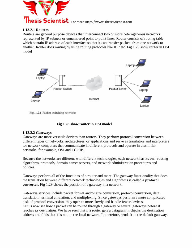
1.13.2.1 Routers
Routers are general purpose devices that interconnect two or more heterogeneous networks
represented by IP subnets or unnumbered point to point lines. Router consists of routing table
which contain IP address of each interface so that it can transfer packets from one network to
another. Router does routing by using routing protocols like RIP etc. Fig 1.28 show router in OSI
model
Fig 1.28 show router in OSI model
1.13.2.2 Gateways
Gateways are more versatile devices than routers. They perform protocol conversion between
different types of networks, architectures, or applications and serve as translators and interpreters
for network computers that communicate in different protocols and operate in dissimilar
networks, for example, OSI and TCP/IP.
Because the networks are different with different technologies, each network has its own routing
algorithms, protocols, domain names servers, and network administration procedures and
policies.
Gateways perform all of the functions of a router and more. The gateway functionality that does
the translation between different network technologies and algorithms is called a protocol
converter. Fig 1.29 shows the position of a gateway in a network.
Gateways services include packet format and/or size conversion, protocol conversion, data
translation, terminal emulation, and multiplexing. Since gateways perform a more complicated
task of protocol conversion, they operate more slowly and handle fewer devices.
Let us now see how a packet can be routed through a gateway or several gateways before it
reaches its destination. We have seen that if a router gets a datagram, it checks the destination
address and finds that it is not on the local network. It, therefore, sends it to the default gateway.

For more Https://www.ThesisScientist.com
The default gateway now searches its table for the destination address. In case the default
gateway recognizes that the destination address is not on any of the networks it is connected to
directly, it has to find yet another gateway to forward it through.
Fig 1.29 shows the position of a gateway in a network.
The routing information the server uses for this is in a gateway routing table linking networks
to gateways that reach them. The table starts with the network entry 0.0.0.0, a catch-all entry, for
default routes. All packets to an unknown network are sent through the default route.
The choice between a router, a bridge, and a gateway is a balance between functionality and
speed. Gateways, as we have indicated, perform a variety of functions; however, because of this
variety of functions, gateways may become bottlenecks within a network because they are slow.
Routing tables may be built either manually for small LANs or by using software called routing
daemons for larger networks.

For more Https://www.ThesisScientist.com
Table 1.3 show comparison between Datagram subnet and Virtual circuit subnet

For more Https://www.ThesisScientist.com
Table 1.4 show comparison between Client/Server and Peer to Peer architecture
Table 1.5 show comparison between Star Topology and Tree Topology

For more Https://www.ThesisScientist.com