basics in minerals processing - metso.com€¦ · basics in mineral processing technical data:...
TRANSCRIPT

Basics in Minerals Processing
BASICS IN MINERAL PROCESSING
CONTENT
Introduction 1
Minerals in operation 2
Size reduction 3 Crushing Grinding
Size control 4 Screening Classification
Enrichment 5 Washing Gravity separation Flotation Magnetic separation Leaching
Upgrading 6 Sedimentation Mechanical dewatering Thermal drying Thermal processing
Materials handling 7 Unloading Storing Feeding Conveying
Slurry handling 8 Slurry transportation Agitation and mixing
Wear in operation 9
Operation and environment 10
Process systems 11
Miscellaneous 12

BASICS IN MINERAL PROCESSING
1. IntroductionBasic definitions _______________________________________________________ 1:1Minerals by value ______________________________________________________ 1:2The process frame of minerals ____________________________________________ 1:3Mineral processing and hardness _________________________________________ 1:4Size and hardness ______________________________________________________ 1:4The stress forces of rock mechanics________________________________________ 1:5
2. Minerals in operationOperation stages ______________________________________________________ 2:1Operation – dry or wet? _________________________________________________ 2:1Mining and quarry fronts ________________________________________________ 2:2Natural fronts _________________________________________________________ 2:2Size reduction _________________________________________________________ 2:4Size control ___________________________________________________________ 2:5Enrichment – washing __________________________________________________ 2:5Enrichment – separation ________________________________________________ 2:6Upgrading ____________________________________________________________ 2:6Materials handling _____________________________________________________ 2:7Wear in operation ______________________________________________________ 2:8Operation and environment _____________________________________________ 2:9Operation values ______________________________________________________ 2:9 3. Size reductionThe size reduction process _______________________________________________ 3:1Feed material _________________________________________________________ 3:2Reduction ratio ________________________________________________________ 3:2The art of crushing _____________________________________________________ 3:3Crushing of rock and gravel ______________________________________________ 3:3Crushing of ore and minerals _____________________________________________ 3:4Crushing – calculation of reduction ratio ___________________________________ 3:5Selection of crushers ___________________________________________________ 3:6Primary crusher – type __________________________________________________ 3:6Primary crusher – sizing _________________________________________________ 3:7Secondary crusher – type _______________________________________________ 3:8Cone crusher – a powerful concept ________________________________________ 3:8Secondary crusher – sizing ______________________________________________ 3:9Final crushing stage – more than just crushing _____________________________ 3:11VSI – a rock protected impactor__________________________________________ 3:11 High Pressure Grinding Rolls (HPGRs) - HRC™ _______________________________ 3:12Final crusher – sizing __________________________________________________ 3:13Wet crushing prior to grinding __________________________________________ 3:14 Technical data: Gyratory crusher – SUPERIOR® MK-II Primary __________________ 3:15Technical data: Jaw crusher – C series _____________________________________ 3:16 Technical data: Impact crusher – NP series _________________________________ 3:17 Technical data: Cone crusher – GPS series _________________________________ 3:18 Technical data: Cone crusher – HP series __________________________________ 3:19 Technical data: Cone crushers – HP 3, 4 and 5 series _________________________ 3:20 Technical data: Cone crusher – MP series __________________________________ 3:21 Technical data: Cone crusher – GP-series __________________________________ 3:22
BASICS IN MINERAL PROCESSING
Technical data: Vertical shaft impactor (VSI) ________________________________ 3:23 Technical data: High pressure grinding rolls (HPGRs) - HRC™ __________________ 3:24 Grinding – introduction ________________________________________________ 3:25Grinding methods ____________________________________________________ 3:25 Grinding mills – reduction ratios _________________________________________ 3:25Grinding – tumbling mills ______________________________________________ 3:26Grinding – stirred mills _________________________________________________ 3:28Grinding – vibrating mills ______________________________________________ 3:29Cost of grinding – typical _______________________________________________ 3:30Mill linings – basic ____________________________________________________ 3:30Grinding mills – sizing _________________________________________________ 3:31 Grinding circuits ______________________________________________________ 3:31 Vertimill® circuits ______________________________________________________ 3:36 Stirred media detritors (SMD) circuits _____________________________________ 3:38Grinding – power calculation ___________________________________________ 3:40Grinding – bonds work index ___________________________________________ 3:40Pulverizing of coal ____________________________________________________ 3:41Vertimill®– more than a grinding mill _____________________________________ 3:42Vertimill® as lime slaker _________________________________________________ 3:43Grinding vs enrichment and upgrading ___________________________________ 3:43 Technical data: AG and SAG mills ________________________________________ 3:44 Technical data: Ball mills _______________________________________________ 3:45 Technical data: Spherical roller bearing supported ball mills __________________ 3:47 Technical data: Conical ball mills _________________________________________ 3:48 Technical data: SRR mill ________________________________________________ 3:49 Technical data: Vertimill® (wide body) _____________________________________ 3:50 Technical data: Vertimill® _______________________________________________ 3:51 Technical data: Vertimill® (lime slaking) ____________________________________ 3:52Technical data: Stirred media grinding mills ________________________________ 3:53 Technical data: Vibrating ball mill ________________________________________ 3:53
4. Size controlSize control – introduction _______________________________________________ 4:1Size control by duties ___________________________________________________ 4:1Size control by methods ________________________________________________ 4:1Screens ______________________________________________________________ 4:2Screening by stratification _______________________________________________ 4:2Screening by free fall ___________________________________________________ 4:2Screen types __________________________________________________________ 4:3Screen capacities ______________________________________________________ 4:3Selection of screening media ____________________________________________ 4:4Particle size – mesh or micron? ___________________________________________ 4:5 Technical data: Single inclination screen – circular motion _____________________ 4:6Technical data: Double inclination screen – linear motion _____________________ 4:7Technical data: Triple inclination screen – linear motion _______________________ 4:8Technical data: Multiple inclination screen – linear motion _____________________ 4:8Classification – introduction _____________________________________________ 4:9Wet classification – fundamentals _________________________________________ 4:9 Hydrocyclone – Introduction ____________________________________________ 4:10Hydrocyclone cluster __________________________________________________ 4:11 Technical data: Hydrocyclone ___________________________________________ 4:12

BASICS IN MINERAL PROCESSING
Spiral classifiers _______________________________________________________ 4:13Dry classification – introduction _________________________________________ 4:15Static classifiers _______________________________________________________ 4:15Dynamic classifiers ____________________________________________________ 4:18Ancillary air solutions __________________________________________________ 4:18Dry grinding _________________________________________________________ 4:20Size control in crushing and grinding circuits _______________________________ 4:22
5. EnrichmentEnrichment – introduction _______________________________________________ 5:1Enrichment – processes _________________________________________________ 5:1Wash water treatment __________________________________________________ 5:3Separation – introduction _______________________________________________ 5:4Separation by gravity ___________________________________________________ 5:4Separation in water ____________________________________________________ 5:4Separation by jigs ______________________________________________________ 5:5 Separation by spiral concentrators ________________________________________ 5:5 Separation by shaking tables _____________________________________________ 5:5 Separation in dense media ______________________________________________ 5:6 Separation by flotation _________________________________________________ 5:7Flotation circuit layout __________________________________________________ 5:8Reactor cell flotation system (RCS) ________________________________________ 5:9Reactor cell flotation system (RCS) – sizing _________________________________ 5:10 Technical data: Flotation machines RCS ___________________________________ 5:13DR flotation cell system ________________________________________________ 5:14 Technical data: Flotation machine DR, metric _______________________________ 5:15 Technical data: Flotation machine DR, US __________________________________ 5:15Column flotation cell system ____________________________________________ 5:17Column flotation – features _____________________________________________ 5:18Magnetic separation – introduction ______________________________________ 5:19 Magnetic separation – methods _________________________________________ 5:20 Magnetic separation – separator types ____________________________________ 5:21Magnetic separation – equipment _______________________________________ 5:21 Dry LIMS, belt drum separator BS ________________________________________ 5:22Technical data: Dry LIMS, belt separator BSA and BSS ________________________ 5:23 Dry LIMS, drum separator DS ____________________________________________ 5:24Technical data: Dry LIMS, drum separator DS _______________________________ 5:25 Wet LIMS – Wet magnetic separators _____________________________________ 5:26Wet LIMS – concurrent (CC) _____________________________________________ 5:26Wet LIMS – counter rotation (CR) and (CRHG) ______________________________ 5:27Wet LIMS – countercurrent (CTC) and CTCHG _______________________________ 5:27Wet LIMS – froth separator (DWHG) ______________________________________ 5:28Wet LIMS – dense media recovery (DM) (DMHG) ____________________________ 5:28 Technical data: Wet LIMS – concurrent (CC) ________________________________ 5:29Technical data: Wet LIMS – counter rotation (CR) and (CRHG) _________________ 5:29Technical data: Wet LIMS – countercurrent (CTC) and CTCHG __________________ 5:30Technical data: Wet LIMS – froth separator (DWHG) __________________________ 5:30 Technical data: Wet LIMS – dense media recovery (DM) (DMHG) _______________ 5:31Wet HGMS/F – magnet design ___________________________________________ 5:32Wet HGMS, HGMF – separator types ______________________________________ 5:32

BASICS IN MINERAL PROCESSING
Wet cyclic HGMS ______________________________________________________ 5:33Wet cyclic HGMS – process system _______________________________________ 5:34Wet cyclic HGMS – operation ____________________________________________ 5:34Wet cyclic HGMS – applications __________________________________________ 5:35Wet cyclic HGMS – sizing _______________________________________________ 5:35 Technical data: Wet cyclic HGMS _________________________________________ 5:36 Wet cyclic high gradiant magnetic filter HGMF _____________________________ 5:37HGMF – applications __________________________________________________ 5:39HGMF – process data __________________________________________________ 5:39HGMF – sizing ________________________________________________________ 5:30 Technical data: Wet cyclic high gradiant magnetic filter HGMF _________________ 5:40Wet continuous HGMS _________________________________________________ 5:41 Wet continuous HGMS – process system __________________________________ 5:41Wet continuous HGMS – applications _____________________________________ 5:41Wet continuous HGMS – sizing and selection _______________________________ 5:42 Technical data: Wet continuous HGMS ____________________________________ 5:43Leaching of metals ____________________________________________________ 5:44 Gold leaching ________________________________________________________ 5:45Gold leaching- carbon adsorption________________________________________ 5:45Gold leaching – CIP ___________________________________________________ 5:46
6. UpgradingUpgrading – introduction _______________________________________________ 6:1 Upgrading by methods _________________________________________________ 6:1 Upgrading by operation costs ____________________________________________ 6:1Sedimentation ________________________________________________________ 6:2 Flocculation __________________________________________________________ 6:2Conventional clarifier ___________________________________________________ 6:3 Conventional clarifier – sizing ____________________________________________ 6:3Conventional thickener _________________________________________________ 6:4 Conventional thickener – sizing __________________________________________ 6:4Conventional clarifier/thickener – design ___________________________________ 6:5Conventional clarifier/thickener – drive system ______________________________ 6:6Conventional clarifier/thickener – drive sizing _______________________________ 6:7Lamella or inclined plate sedimentation – introduction _______________________ 6:9Inclined plate settler (IPS) ______________________________________________ 6:11Inclined plate settler – drives ____________________________________________ 6:12Inclined plate settler – product range _____________________________________ 6:13 Technical data: Inclined plate settler (LT) __________________________________ 6:16Technical data: Inclined plate settler (LTS) _________________________________ 6:17Technical data: Inclined plate settler (LTK) _________________________________ 6:18Technical data: Inclined plate settler (LTE) _________________________________ 6:19Technical data: Inclined plate settler (LTE/C) ________________________________ 6:20Technical data: Inclined plate settler (LTC) _________________________________ 6:21Mechanical dewatering – introduction ____________________________________ 6:22Mechanical dewatering – methods and products ___________________________ 6:22Gravimetric dewatering ________________________________________________ 6:23Spiral dewaterer ______________________________________________________ 6:23Technical data: Spiral dewaterer _________________________________________ 6:24Sand screw __________________________________________________________ 6:25

BASICS IN MINERAL PROCESSING
Dewatering screen ____________________________________________________ 6:25Dewatering wheel ____________________________________________________ 6:25Mechanical dewatering by pressure – introduction __________________________ 6:26 Drum vacuum filters ___________________________________________________ 6:26Belt drum filters ______________________________________________________ 6:27Top feed filters _______________________________________________________ 6:27Vacuum filters – vacuum requirements ____________________________________ 6:28Vacuum plant – arrangement ___________________________________________ 6:28 Vertical plate pressure filter – introduction _________________________________ 6:29Vertical plate pressure filter – design _____________________________________ 6:30Pressure filter VPA – operation ___________________________________________ 6:30Pressure filter VPA – sizes _______________________________________________ 6:32Pressure filter VPA – chamber data _______________________________________ 6:32Pressure filter VPA – nomenclature _______________________________________ 6:32Pressure filter VPA – sizing ______________________________________________ 6:33Pressure filter VPA – moisture in filter cake _________________________________ 6:34Pressure filter VPA – compressor sizing ____________________________________ 6:34Pressure filter VPA – compressor power ___________________________________ 6:35Pressure filter VPA – feed pump selection __________________________________ 6:35Pressure filter VPA – feed pump power ____________________________________ 6:35Pressure filter VPA – product system ______________________________________ 6:36 Technical data: Pressure filter VPA 10 _____________________________________ 6:37Technical data: Pressure filter VPA 15 _____________________________________ 6:38Technical data: Pressure filter VPA 20 _____________________________________ 6:39Tube press – introduction ______________________________________________ 6:40Tube press – design ___________________________________________________ 6:41Tube press – operation _________________________________________________ 6:42Tube press – applications _______________________________________________ 6:43Tube press – material of construction _____________________________________ 6:44Tube press – sizes _____________________________________________________ 6:45Tube press – sizing ____________________________________________________ 6:45Tube press – cycle times and cake moisture ________________________________ 6:46Tube press – capacity __________________________________________________ 6:46Tube press – product system ____________________________________________ 6:47 Tube press – booster system ____________________________________________ 6:48Tube press – mechanical description _____________________________________ 6:49 Technical data: Tube press ______________________________________________ 6:50Thermal processing – introduction _______________________________________ 6:51Direct heat rotary dryer (cascade type) ____________________________________ 6:52Indirect heat rotary dryer (kiln) __________________________________________ 6:52Fluidized bed ________________________________________________________ 6:53Indirect heat screw dryer (Holo-flite®) _____________________________________ 6:55Holo-flite® process system ______________________________________________ 6:55Technical data: Indirect heat screw dryer (Holo-flite®) ________________________ 6:57Fluidized bed ________________________________________________________ 6:54Something about cooling ______________________________________________ 6:58Iron ore pelletizing ____________________________________________________ 6:59Pellet plant schematic _________________________________________________ 6:60Feed preparation _____________________________________________________ 6:61Grate Kiln technology _________________________________________________ 6:62

BASICS IN MINERAL PROCESSING
Major process equipment components of iron ore pellet plant ________________ 6:65Design criteria and plant sizing __________________________________________ 6:67Comparisons of indurating technologies __________________________________ 6:68Lime calcining system _________________________________________________ 6:70Coke calcining system _________________________________________________ 6:73Tire pyrolysis _________________________________________________________ 6:74
7. Materials handlingIntroduction __________________________________________________________ 7:1Loading and unloading _________________________________________________ 7:1Railcar dumpers _______________________________________________________ 7:1Train positioners _______________________________________________________ 7:2Unloaders ____________________________________________________________ 7:3Storage buffering ______________________________________________________ 7:5Stacker reclaimer ______________________________________________________ 7:6Scraper reclaimer ______________________________________________________ 7:6Barrel reclaimer________________________________________________________ 7:7Feeding ______________________________________________________________ 7:8 Technical data sheets Technical data: Feeder – Apron __________________________________________ 7:10Technical data: Feeder – Vibration _______________________________________ 7:11Technical data: Feeder – Unbalanced motor ________________________________ 7:12Technical data: Feeder – Belt ____________________________________________ 7:13Technical data: Feeder – Electromagnetic __________________________________ 7:14Technical data: Feeder – Wobbler ________________________________________ 7:15Conveying ___________________________________________________________ 7:16Conveying systems ____________________________________________________ 7:17Conveyor capacities ___________________________________________________ 7:18Volume weight and angle of inclination ___________________________________ 7:18Conveyor - more than a rubber belt ______________________________________ 7:19 Technical data: Conveyor – Standard belt __________________________________ 7:20 Vertical conveyor system _______________________________________________ 7:21
8. Slurry handlingSlurry handling – introduction ___________________________________________ 8:1Basic definitions _______________________________________________________ 8:2Technical description ___________________________________________________ 8:6Metso slurry pump series and sizes ________________________________________ 8:7Metso horizontal slurry pump wet-end modular configurations ________________ 8:8 Metso vertical slurry pump wet-end modular configurations ___________________ 8:9Slurry pump range MD _________________________________________________ 8:10Slurry pumps – range XM _______________________________________________ 8:11Dredge pumps – range Thomas _________________________________________ 8:12Slurry pumps – range VASA HD and XR ____________________________________ 8:13Slurry pumps – range HR and HM ________________________________________ 8:14Slurry pumps – range MR and MM _______________________________________ 8:15Slurry pumps – range VT _______________________________________________ 8:16Slurry pumps – range VF _______________________________________________ 8:17Slurry pumps – range VS _______________________________________________ 8:18 Slurry pumps – range VSHM , VSHR and VSMM _____________________________ 8:19 Application guide for slurry pumps _______________________________________ 8:20

BASICS IN MINERAL PROCESSING
Selection – by solids ___________________________________________________ 8:21 Selection – by head and volume ________________________________________ 8:21 Selection – by slurry type _______________________________________________ 8:22 Selection – by industrial application ______________________________________ 8:23 Industrial segment: Construction ________________________________________ 8:24 Industrial segment: Coal _______________________________________________ 8:25 Industrial segment: Waste and recycling___________________________________ 8:25Industrial segment: Power and FGD ______________________________________ 8:25 Industrial segment: Pulp and paper ______________________________________ 8:26Industrial segment: Metallurgy __________________________________________ 8:26Industrial segment: Chemical ___________________________________________ 8:27Industrial segment: Mining _____________________________________________ 8:27Slurry transport ______________________________________________________ 8:28Slurry pipeline sizing __________________________________________________ 8:29Wear _______________________________________________________________ 8:31Slurry valves introduction ______________________________________________ 8:35Slurry valves _________________________________________________________ 8:37 9. Wear in operationIntroduction __________________________________________________________ 9:1Wear in operation – caused by ___________________________________________ 9:1Wear by compression ___________________________________________________ 9:2Wear by impaction (high) _______________________________________________ 9:2Wear by impaction (low) ________________________________________________ 9:3Wear by sliding ________________________________________________________ 9:3Wear protection and products ____________________________________________ 9:4 Wear products – application _____________________________________________ 9:4Heavy impact – selection ________________________________________________ 9:5Impact and sliding – selection (modules) ___________________________________ 9:5Impact and sliding – selection (sheeting) ___________________________________ 9:6 Sliding and build up – selection __________________________________________ 9:6Wear protection – wear parts ____________________________________________ 9:7Wear parts – slurry pumps ______________________________________________ 9:10Something about ceramic liners _________________________________________ 9:11Wear in slurry pipelines ________________________________________________ 9:12
10. Operation and environmentOperation and environment – introduction ________________________________ 10:1Dust ________________________________________________________________ 10:1Dust control – basic ___________________________________________________ 10:2Noise _______________________________________________________________ 10:4Noise reduction ______________________________________________________ 10:5Ear protection ________________________________________________________ 10:7
11. Process systemProcess system – Introduction ___________________________________________ 11:1System modules – aggregates ___________________________________________ 11:2 System modules – sand & gravel _________________________________________ 11:2 System modules – ore & minerlas ________________________________________ 11:3 Process system – railway ballast _________________________________________ 11:4 Process system – asphalt / concrete ballast ________________________________ 11:4
BASICS IN MINERAL PROCESSING
Process system – ferrous ore ____________________________________________ 11:5 Process system – base metal ore _________________________________________ 11:5Process system – gold bearing ore _______________________________________ 11:6 Process system – coal __________________________________________________ 11:6 Process system – industrial mineral fillers __________________________________ 11:7 Process system – glass sand _____________________________________________ 11:7Process system – diamond (kimberlite) ____________________________________ 11:8Process system – kaolin ________________________________________________ 11:8 Mobile systems _______________________________________________________ 11:9 Technical data: Primary jaw crusher + grizzly ______________________________11:10 Technical data: Primary impact crusher + grizzly ___________________________11:10 Metso simulation tools ________________________________________________11:11 Consulting business __________________________________________________11:11 Process Technology and Innovation _____________________________________11:12
12. MiscellaneousConversion factors ____________________________________________________ 12:1Tyler standard scale ___________________________________________________ 12:2Density of solids ______________________________________________________ 12:3Water and solids – pulp density data (metric and imperial) ____________________ 12:5

BASICS IN MINERAL PROCESSING
Metso mining and aggregatesBrand names in minerals processing and aggregatesAllis Chalmers (AC)Allis Minerals System Altairac Armstrong Holland Barmac Bergeaud Boliden AllisCable Belt Conrad Scholtz Denver Dominion FACOGFA HardingeHewitt Robins Kennedy Van Saun KVS Kue-ken SecoKoppers LenningsLokomoMarcyMasterscreens McDowell Wellman
McNally WellmanNeims NICONokia NolanNordbergMPSI Orion PECOPyrotherm Read REDLER Sala ScampSkegaStansteelStephens – AdamsonStrachan & HenshawSvedala Thomas TidcoTrellex Tyler

1:1
Introduction
Intr
oduc
tion
BASICS IN MINERAL PROCESSING
“The practice of minerals processing is as old as human civilization. Minerals and products derived from minerals have formed our development cultures from the flints of the Stone Age man to the uranium ores of Atomic Age”.
The ambition with this handbook, “Basics in Minerals Processing”, is not to give a full coverage of the subject above.
The intention is to give technicians involved in mineral operations practical and useful information about the process equipment used, their systems and operational environment.
The technical data given are basic, but will increase the understanding of the individual machines, their functions and performances.
Always contact Metso for information regarding specific products since the data given is subject to change without notice.
Basic definitionsIt is important to know the definitions of mineral, rock and ore as they represent different product values and partly different process systems
Mineral Rock Ore
Na+
Ca2+ Si4+ O2-
CO22- Fe2+ OH-
Heat Pressure Heat Pressure Heat Pressure Deformation Chemical activity
“Natural components of “Compounds of minerals” “Rocks containing minerals or chemical elements” metals which can be recovered with profit”
Artificial minerals
“Man made” minerals are not minerals by definitions. But from processing point of view they are similar to virgin minerals and are treated accordingly (mainly in recycling processes).
Slag Concrete Mill scale Glass & Ceramics
Min
eral
Min
eral
Min
eral
Rock
Rock
Rock
Rock
Ore
Ore
Ore
SiO
2
Ca C
o 3
Fe2 O
3

1:2
Introduction
Intr
oduc
tion
BASICS IN MINERAL PROCESSING
Abr
asiv
es
Coru
ndum
Q
uart
zD
iam
ond
a.o.
Gla
ssQ
uart
zFe
ldsp
arCa
lcite
Dol
omite
a.o
.
Plas
ticCa
lcite
Kaol
inTa
lcW
olla
ston
iteM
ica
a.o.
Cera
mic
sQ
uart
zKa
olin
Feld
spar
a.o
.
Fert
ilise
rsPh
osph
ate
Pota
shCa
lcite
Dol
omite
a.o
.
Fille
rs a
nd p
igm
ent
Barit
eBe
nton
iteCa
lcite
Dol
omite
Feld
spar
Talc
a.o
.
Refr
acto
ries
Wol
last
onite
Calc
iteD
olom
iteCo
rund
um a
.o.
Base
met
als
Copp
erLe
adZi
nc a
.o.
Ligh
t met
als
Alu
min
ium
Mag
nesi
umTi
tani
um
Prec
ious
met
als
Gol
dSi
lver
Plat
inum
a.o
.
Rare
met
als
Ura
nium
Radi
umBe
rylli
um a
.o.
Allo
ying
met
als
Chro
miu
mVa
nadi
umM
olyb
denu
mTu
ngst
ena.
o.
Iron
Min
eral
s by
valu
e
Coal
sO
il sh
ale
(Oil
sand
)
Conc
rete
bal
last
Asp
halt
balla
stRo
ck fi
llIn
dust
rial s
and
a.o.
Agg
rega
te, s
and
& g
rave
l
Non
-fer
rous
F
erro
us a
lloy
Fer
rous
Indu
stri
al m
iner
als
Min
eral
fuel
s
Min
eral
s Rock
Ore
s

1:3
Introduction
Intr
oduc
tion
BASICS IN MINERAL PROCESSING
The process frame of minerals The goal in mineral processing is to produce maximum value from a given raw material. This goal can be a crushed product with certain size and shape or maximum recovery of metals out of a complex ore.The technologies to achieve these goals are classical, complementary and well defined.Below they are presented in the Process Frame of Minerals, classified according to their interrelations in product size and process environment (dry or wet).
Drilling (and blasting) is the technology of achieving primary fragmentation of “in situ” minerals. This is the starting point for most mineral processes with the exception of natural minerals in the form of sand and gravel.
Crushing and screening is the first controlled size reduction stage in the process. This is the main process in aggregate production and a preparation process for further size reduction.
Grinding is the stage of size reduction (wet or dry) where the liberation size for individual minerals can be reached. By further size reduction filler (mineral powder) is produced.
Slurry processing includes the technologies for wet processing of mineral fractions.
Pyro processing includes the technologies for upgrading of the mineral fractions by drying, calcining or sintering.
Materials handling includes the technologies for moving the process flow (dry) forward by loading, transportation, storage and feeding.
Compaction of minerals includes the technologies for moving and densifying minerals by vibration, impaction and pressure, mainly used in construction applications.
Size 1m 100 mm 10 mm 1 mm 100 micron 10 micron 1 micron8
1:4
Introduction
Intr
oduc
tion
BASICS IN MINERAL PROCESSING
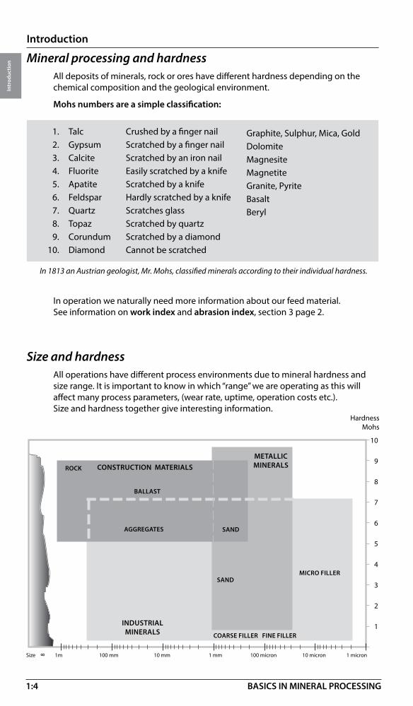
In 1813 an Austrian geologist, Mr. Mohs, classified minerals according to their individual hardness.
Crushed by a finger nailScratched by a finger nailScratched by an iron nailEasily scratched by a knifeScratched by a knifeHardly scratched by a knifeScratches glassScratched by quartzScratched by a diamondCannot be scratched
Graphite, Sulphur, Mica, Gold Dolomite Magnesite Magnetite Granite, Pyrite Basalt Beryl
Mineral processing and hardnessAll deposits of minerals, rock or ores have different hardness depending on the chemical composition and the geological environment.
Mohs numbers are a simple classification:
Size and hardness All operations have different process environments due to mineral hardness and size range. It is important to know in which “range” we are operating as this will affect many process parameters, (wear rate, uptime, operation costs etc.). Size and hardness together give interesting information.
In operation we naturally need more information about our feed material. See information on work index and abrasion index, section 3 page 2.
1. Talc 2. Gypsum 3. Calcite 4. Fluorite 5. Apatite 6. Feldspar 7. Quartz 8. Topaz 9. Corundum 10. Diamond
10
9
8
7
6
5
4
3
2
1
HardnessMohs
INDUSTRIALMINERALS
ROCK
BALLAST
SAND
METALLIC MINERALSCONSTRUCTION MATERIALS
AGGREGATES
COARSE FILLER FINE FILLER
SAND
MICRO FILLER
Size 1m 100 mm 10 mm 1 mm 100 micron 10 micron 1 micron8
1:5
Introduction
Intr
oduc
tion
BASICS IN MINERAL PROCESSING
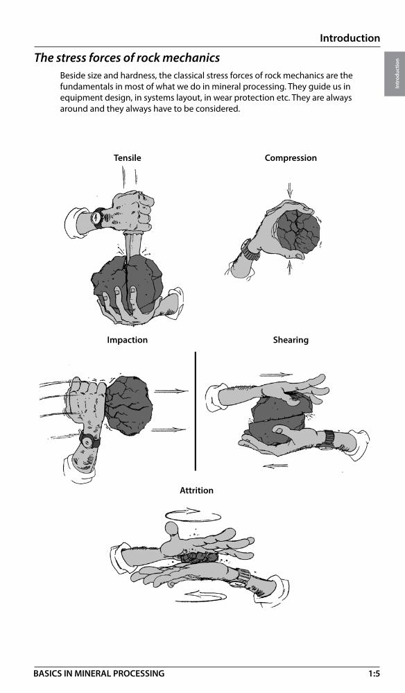
The stress forces of rock mechanicsBeside size and hardness, the classical stress forces of rock mechanics are the fundamentals in most of what we do in mineral processing. They guide us in equipment design, in systems layout, in wear protection etc. They are always around and they always have to be considered.
Tensile Compression
Impaction Shearing
Attrition

2:1
Minerals in operation
BASICS IN MINERAL PROCESSING
Min
eral
s in
oper
atio
n
Operation stagesThe operating stages in minerals processing have remained the same for thousands of years. Of course we have come far in development of equipment and processes since then, but the hard, abrasive and inhomogeneous mineral crystals have to be treated in special ways in order to extract maximum value out of each size fraction.The operation pattern below has been used since the days of “ mineralis antiqua”
Front service: Starting point of mineral processingSize reduction & control: Processes to produce requested size distributions from
feed materialEnrichment: Processes to improve value of minerals by washing
and/or separationUpgrading: Processes to produce requested end products from
value and waste minerals.Materials handling: Operations for moving the processes forward with a
minimum of flow disturbancesProtection: Measures to protect the process environment above
from wear and emissions of dust and sound
Operation – Dry or wet ?
FRONTSERVICE
SIZEREDUCTION
AND CONTROL
ENRICHMENT UPGRADING
MATERIALS HANDLING
PROTECTION
Note! Wear rate is generally higher in wet processing!
In all other cases due to:• Better efficiency• More compact installation• No dusting
• When no water is needed for processing
• When no water is allowed for processing
Dry processing Wet processing

2:2
Minerals in operation
BASICS IN MINERAL PROCESSING
Min
eral
s in
oper
atio
n
Mining and quarry fronts The mining and quarry fronts are the starting points for recovery of rock and mineral values from surface and underground deposits.
Operations are drilling (blasting), primary crushing (optional) and materials handling, dry and wet.
Underground
Natural fronts In the glacial, alluvial and marine fronts nature has done most of the primary size reduction work.
Raw material such as gravel, sand and clay are important for processing of construction ballast, metals and industrial mineral fillers.
Operations are materials handling (wet and dry) and front crushing (optional).
GlacialGlacial sand and gravel occur in areas which are – or have been – covered by ice. The material is rounded and completely unsorted with an heterogeneous size distribution which ranges from boulders larger than 1 m (3 ft) down to silt (2-20 microns). Clay contamination is concentrated in well defined layers.
Open pit
Mining and quarrying
2:3
Minerals in operation
BASICS IN MINERAL PROCESSING
Min
eral
s in
oper
atio
n
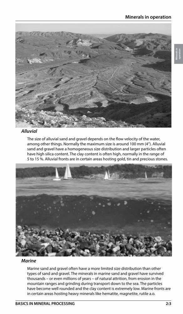
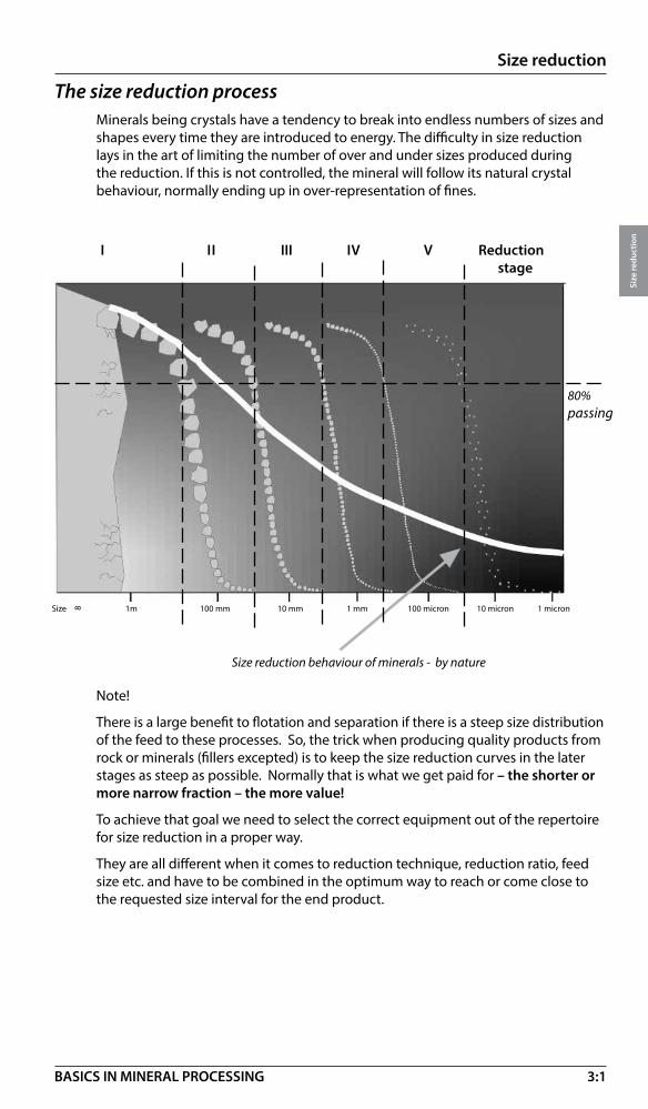
MarineMarine sand and gravel often have a more limited size distribution than other types of sand and gravel. The minerals in marine sand and gravel have survived thousands – or even millions of years – of natural attrition, from erosion in the mountain ranges and grinding during transport down to the sea. The particles have become well rounded and the clay content is extremely low. Marine fronts are in certain areas hosting heavy minerals like hematite, magnetite, rutile a.o.
AlluvialThe size of alluvial sand and gravel depends on the flow velocity of the water, among other things. Normally the maximum size is around 100 mm (4”). Alluvial sand and gravel have a homogeneous size distribution and larger particles often have high silica content. The clay content is often high, normally in the range of 5 to 15 %. Alluvial fronts are in certain areas hosting gold, tin and precious stones.

2:4
Minerals in operation
BASICS IN MINERAL PROCESSING
Min
eral
s in
oper
atio
n
Size reductionCrushing of rock and minerals
By tonnage this is by far the largest process operation in minerals processing. The goal is to produce rock or (more seldom) mineral fractions to be used as rock fill or ballast material for concrete and asphalt production. Quality parameters are normally strength, size and shape. The size fractions, see below, are priced according to defined size intervals and can be reached by crushing only, see section 3.
>1000 >500 >100 >80 64 32 22 16 11 8 4 0 Size mm
PRIMARY GYRATORYCRUSHER
JAWCRUSHER
CRUSHERS
CONE CRUSHERSECONDARY
VSI
CONECRUSHER TERTIARY
Product value
Crushing and grinding of ore and mineralsSize reduction of ores is normally done in order to liberate the value minerals from the host rock. This means that we must reach the liberation size, normally in the interval 100 – 10 micron, see value curve 1 above. If the raw material is a single mineral (Calcite, Feldspar a.o.) the value normally lays in the production of very fine powder (filler), see value curve 2 below.In order to maximise the value in size reduction of rock and minerals, see below, we need both crushing and grinding in various combinations, see section 3.
IMPACTORSHSIPRIMARY AND SECONDARY CRUSHER
1 m 100 mm 1 0 mm 1 mm 100 micron 10 micron 1 micron
100 micron
PRIMARY GYRATORYCRUSHER
JAWCRUSHER VSI
CONECRUSHER
CRUSHERS/ IMPACTORS
MILLS
STIRRED MEDIA DETRITOR
VERTIMILL
PEBBLE
BALL
1.
2.
Size
8
The equipment shown below is a general application range. The actual range depends on the material properties and process requirements.
AG/SAG
ROD
HRC

2:5
Minerals in operation
BASICS IN MINERAL PROCESSING
Min
eral
s in
oper
atio
n
1 m 10 mm 10 mm 1 mm 100 micron 10 micron 1 micron
100 micron
Size controlNeither crushers nor grinding mills are very precise when it comes to the correct sizing of the end products. The reason is to find partly in the variation of the mineral crystals compounds (hard-soft, abrasive – non abrasive), partly in the design and performance of the equipment.
Size control is the tool for improvement of the size fractions in the process stages and in the final products.For the coarser part of the process, screens are used (in practise above 1-2 mm). In the finer part we have to use classification with spiral classifiers, see section 4.
Enrichment – WashingWashing is the simplest method of enrichment used to improve the value of rock and mineral fractions from sand size and upwards. Removing of surface impurities like clay, dust, organics or salts is often a must for a saleable product.Different techniques are used depending on how hard these impurities are attached to the rock or mineral surface, see section 5.
Washing using Wet screens* Scrubbers* Attrition cells* Gravity beds*
* Contact Metso for further information.
Size 8

2:6
Minerals in operation
BASICS IN MINERAL PROCESSING
Min
eral
s in
oper
atio
n
Enrichment – SeparationMost value minerals (both metallic and industrial) are priced by their purity. After liberation by size reduction and size control all minerals are free to be separated from each other.
Depending on the properties of the individual minerals they can be recovered by different methods of separation, see section 5.
DEWATERING BY PRESSURE FILTERS
DEWATERING BY VACUUM FILTERS
SEDIMENTATION
SINTERING
DEWATERING BY TUBE PRESSES
DEWATERING BY SCREENSDEWATERING BY SPIRALS
Size 100 mm 10 mm 1 mm 100 micron 10 micron 1 micron
UpgradingAfter the enrichment operation we end up with a value product (concentrate) and a non-value product (tailings).
These products are probably not sellable nor disposable due to the content of process water, particle size, or chemical composition.
By upgrading we mean the methods of increasing the value of these products by sedimentation, mechanical dewatering, drying, calcining or sintering and recovering the process water from the tailings, making them disposable, see section 6.
Gravimetric Flotation Magnetic Leaching
� ������ �
Upgrading by methods
DRYING
Gravity Air
• = value mineral
CALCINING
RELATIVE COST

2:7
Minerals in operation
BASICS IN MINERAL PROCESSING
Min
eral
s in
oper
atio
n
Materials handlingWithout a proper set up for materials handling no processing system will perform. Different process stages may be in various locations, may have various feed conditions, are on different shift cycles etc.
Materials handling of dry material is based on the operations of loadíng, unloading, transportation, storing and feeding, see section 7.
Materials handling of wet material, called slurry handling is also based on the operations of transportation (by slurry pumps and hoses), feeding (by slurry pumps) and storage (by slurry agitation), see section 8.
�����
����
�����
����
������
��
Dry handling
Slurry handling

2:8
Minerals in operation
BASICS IN MINERAL PROCESSING
Min
eral
s in
oper
atio
n
Wear in operationWhenever energy in any form penetrates rock, ore or mineral, wear will appear.
There is of course a difference whether the minerals are hard or soft, small or large, abrasive or non-abrasive, wet or dry, but wear will always be around. Both machines and structures must be protected from wear using metals, polymers or compound material.
See section 9, wear in operation.

2:9
Minerals in operation
BASICS IN MINERAL PROCESSING
Min
eral
s in
oper
atio
n
Operation and environmentIf wear is dangerous for equipment and structures, dust and noise is primarily a danger to the operators.
Dust is a problem to both equipment and operators in dry processing
Noise is a problem to operators both in wet and dry processing.
By tradition, the environment in mineral processing has a bad reputation.
This is now changing fast due to harder restrictions by law and harder demands from the operators, see section 10, Operation and environment.
Operation valuesPrices for products from your operation are seldom set by yourself, but by the market buying them. There is always a possibility to increase the income from your operation by added values generated by the operation itself.
• By improving the output we can increase the product volumes• By improving the quality we can increase the price of our products• By improving the cost control we can reduce our costs of operation• By improving the comfort for our operators we can improve motivation and
reduce disturbances in operationThis can be done by small adjustments, by improved service or by reinvestment in more effective equipment, see all sections.
Added value in operationVOLUME x PRICE – COSTS + MOTIVATION = S
Output Quality Cost control Comfort
AVAILABILITY(up time)
SIZE /SHAPE CAPITAL SECURITY
CAPACITYPURITY /
RECOVERY ENERGY ENVIRON-MENT
FLEXIBILITYCOMPAC-
TION / DENSITY
MATERIAL RELATIONS
3:1
Size reduction
Size
redu
ctio
n
BASICS IN MINERAL PROCESSING
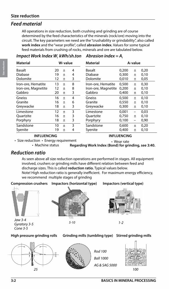
The size reduction processMinerals being crystals have a tendency to break into endless numbers of sizes and shapes every time they are introduced to energy. The difficulty in size reduction lays in the art of limiting the number of over and under sizes produced during the reduction. If this is not controlled, the mineral will follow its natural crystal behaviour, normally ending up in over-representation of fines.
Size reduction behaviour of minerals - by nature
Note!
There is a large benefit to flotation and separation if there is a steep size distribution of the feed to these processes. So, the trick when producing quality products from rock or minerals (fillers excepted) is to keep the size reduction curves in the later stages as steep as possible. Normally that is what we get paid for – the shorter or more narrow fraction – the more value!
To achieve that goal we need to select the correct equipment out of the repertoire for size reduction in a proper way.
They are all different when it comes to reduction technique, reduction ratio, feed size etc. and have to be combined in the optimum way to reach or come close to the requested size interval for the end product.
I II III IV V Reduction stage
80%passing
Size 1m 100 mm 10 mm 1 mm 100 micron 10 micron 1 micron8
3:2
Size reduction
Size
redu
ctio
n
BASICS IN MINERAL PROCESSING
Impact Work Index Wi kWh/sh.ton Abrasion index = Ai
Material Wi value
Basalt 20 ± 4Diabase 19 ± 4Dolomite 12 ± 3Iron-ore, Hematite 13 ± 8Iron-ore, Magnetite 12 ± 8Gabbro 20 ± 3Gneiss 16 ± 4Granite 16 ± 6Greywacke 18 ± 3Limestone 12 ± 3Quartzite 16 ± 3 Porphyry 18 ± 3Sandstone 10 ± 3Syenite 19 ± 4
Material Ai value
Basalt 0,200 ± 0,20 Diabase 0,300 ± 0,10Dolomite 0,010 ± 0,05Iron-ore, Hematite 0,500 ± 0,30Iron-ore, Magnetite 0,200 ± 0,10Gabbro 0,400 ± 0,10Gneiss 0,500 ± 0,10Granite 0,550 ± 0,10Greywacke 0,300 ± 0,10Limestone 0,001 – 0,03Quartzite 0,750 ± 0,10Porphyry 0,100 – 0,90Sandstone 0,600 ± 0,20Syenite 0,400 ± 0,10
INFLUENCING• Size reduction • Energy requirement
• Machine status
INFLUENCING• Wear rate
Feed material All operations in size reduction, both crushing and grinding are of course determined by the feed characteristics of the minerals (rock/ore) moving into the circuit. The key parameters we need are the “crushability or grindability”, also called work index and the “wear profile”, called abrasion index. Values for some typical feed materials from crushing of rocks, minerals and ore are tabulated below.
Reduction ratioAs seen above all size reduction operations are performed in stages. All equipment involved, crushers or grinding mills have different relation between feed and discharge sizes. This is called reduction ratio. Typical values below. Note! High reduction ratio is generally inefficient. For maximum energy efficiency, we recommend multiple stages of grinding
Compression crushers Impactors (horizontal type)
Jaw 3-4Gyratory 3-5Cone 3-5
1-2
Rod 100
Ball 1000
AG & SAG 5000
Impactors (vertical type)
Regarding Work Index (Bond) for grinding, see 3:40.
Grinding mills (tumbling type) Stirred grinding mills
5-10
High pressure grinding rolls
10025
3:3
Size reduction
Size
redu
ctio
n
BASICS IN MINERAL PROCESSING
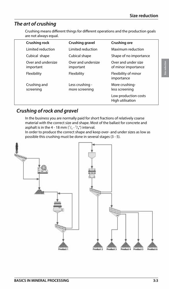
The art of crushingCrushing means different things for different operations and the production goals are not always equal.
Crushing rock Crushing gravel Crushing ore
Limited reduction Limited reduction Maximum reduction
Cubical shape Cubical shape Shape of no importance
Over and undersize Over and undersize Over and under size important important of minor importance
Flexibility Flexibility Flexibility of minor importance
Crushing and Less crushing - More crushing- screening more screening less screening
Low production costs High utilisation
Impactors (vertical type)
Crushing of rock and gravelIn the business you are normally paid for short fractions of relatively coarse material with the correct size and shape. Most of the ballast for concrete and asphalt is in the 4 - 18 mm (1/5 - 3/4’’) interval. In order to produce the correct shape and keep over- and under sizes as low as possible this crushing must be done in several stages (3 - 5).

3:4
Size reduction
Size
redu
ctio
n
BASICS IN MINERAL PROCESSING
Crushing of ore and mineralsIn these operations the value is achieved at the fine end, say below 100 micron (150 mesh).Normally the size reduction by crushing is of limited importance besides the top size of the product going to grinding.This means that the number of crushing stages can be reduced depending on the feed size accepted by primary grinding stage.
”Classical” 3-stage crushing prior to rod mill
Typical 3- stage crushing prior to ball mill
Typical 1-2 stage ore crushing in AG-SAG circuit
Primary crushing
Secondary crushing
Tertiary crushing
Tertiary crushing
Primary crushing
Secondary crushing
Primary crushing
Primary grinding
Secondary crushing
3-stage crushing utilizing an HPGR prior to a rod mill or ball mill
Another option is including HPGRs in the crushing circuit. Commons circuits include utilizing HPGRs as a:– tertiary crusher, followed by a ball mill or VERTIMILL®– quarternary crusher, followed by a ball mill or VERTIMILL®– pebble crusher in a SABC circuit
Primary crushing
Secondary crushing
Tertiary crushing
HPGR crusher
3:5
Size reduction
Size
redu
ctio
n
BASICS IN MINERAL PROCESSING
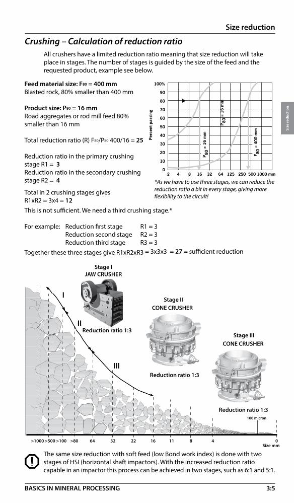
Feed material size: F80 = 400 mmBlasted rock, 80% smaller than 400 mm
Product size: P80 = 16 mmRoad aggregates or rod mill feed 80% smaller than 16 mm
Total reduction ratio (R) F80/P80 400/16 = 25
Reduction ratio in the primary crushing stage R1 = 3Reduction ratio in the secondary crushing stage R2 = 4
Total in 2 crushing stages gives R1xR2 = 3x4 = 12This is not sufficient. We need a third crushing stage.*
For example: Reduction first stage R1 = 3 Reduction second stage R2 = 3 Reduction third stage R3 = 3Together these three stages give R1xR2xR3 = 3x3x3 = 27 = sufficient reduction
Crushing – Calculation of reduction ratioAll crushers have a limited reduction ratio meaning that size reduction will take place in stages. The number of stages is guided by the size of the feed and the requested product, example see below.
The same size reduction with soft feed (low Bond work index) is done with two stages of HSI (horizontal shaft impactors). With the increased reduction ratio capable in an impactor this process can be achieved in two stages, such as 6:1 and 5:1.
100 micron
JAW CRUSHER
CONE CRUSHER
CONE CRUSHER
Reduction ratio 1:3
Reduction ratio 1:3
Stage I
Stage II
Stage III
I
II
III
Reduction ratio 1:3
>1000 >500 >100 >80 64 32 22 16 11 8 4 0 Size mm
*As we have to use three stages, we can reduce the reduction ratio a bit in every stage, giving more flexibility to the circuit!
����
��
��
��
��
��
��
��
��
��
��������������������������������������������������������������
���
���
���
��
�����
�����
�
�����
�����
�
� ����
������
�

3:6
Size reduction
Size
redu
ctio
n
BASICS IN MINERAL PROCESSING
Selection of crushersKnowing the number of crushing stages we can now start to select the correct crusher for each reduction stage. Depending on operating conditions, feed size, capacity, hardness etc, there are always some options. For primary crushers, see below.
Stationary crushers – surface and underground
Mobile Crushers
For mobile crushers see further section 11:9
Primary crusher – TypeFor soft feed and non-abarasive feed (low Bond work index) a horizontal Impactor (HSI) is an option if the capacity is not too high.
For harder feed there is a choice between a gyratory or a jaw crusher, see below.
Note: HSI can be used only if the abrasion index is lower and the plant does not mind fines production. Otherwise, a jaw crusher is preferred for lower capacity aggregate plants.)
Primary Gyratory
Feed opening Feed openingJaw crusher Gyratory crusher
Discharge opening Discharge openingJaw crusher Gyratory crusher
Rule 1: Always use a jaw crusher if you can, jaws are the least capital cost.
Rule 2: For low capacity use jaw crusher and hydraulic hammer for oversize.
Rule 3: For high capacities (800-1500 tph)use jaw crusher with big intake opening.
Rule 4: For very high capacities (1200+ tph use gyratory crusher.
Jaw Impact
Jaw + grizzly Impact + grizzly

3:7
Size reduction
Size
redu
ctio
n
BASICS IN MINERAL PROCESSING
500 1000 1500 2000
MK-II 54 - 75
MK-II 60 - 110 E
Capacity t/h
Feed top size mm (inch: divide by 25)
1500
1000
500
2000 3000 4000 5000 6000 7000 8000 9000
Primary crusher – SizingCrushers are normally sized from top size of feed. At a certain feed size, knowing the capacity, we can select the correct machine, see below.
A correct sizing of any crusher is not easy and the charts below can only be used for guidance.
Ex. Feed is a blasted hard rock ore with top size 750 mm. Capacity is 4750 t/h.• Which primary crusher can do the job? • Check on the two compression machines below and take out the sizing point! • Correct selection is Superior® MK-II Primary Gyratory Crusher type MK-II 60-89
Primary gyratory – Feed size vs capacity
Primary jaw crusher – Feed size vs capacity
Primary impactor – Feed size vs capacity Feed top size mm (inch: divide by 25)
1500
1300
1000900
700600
400350
Capacity t/h
NP1620
NP2023
NP1415NP1313
Data sheet, see 3:15
Data sheet, see 3:17
MK-II 62 - 75 MK-II 60 - 89MK-II 50 - 65
MK-II 42 - 65
00
0%
10%
20%
30%
40%
50%
60%
70%
80%
90%
100%
0,1 1 10 100 1000
3:8
Size reduction
Size
redu
ctio
n
BASICS IN MINERAL PROCESSING
Jaw Crusher
• Big feed opening• High capacity• Controlled feed• Shape
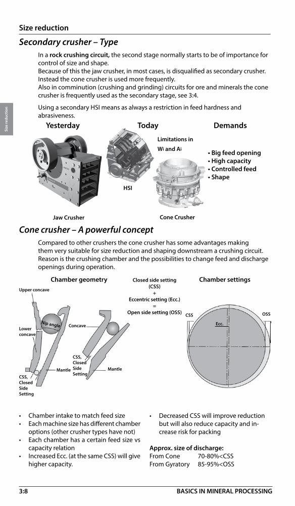
Secondary crusher – TypeIn a rock crushing circuit, the second stage normally starts to be of importance for control of size and shape.Because of this the jaw crusher, in most cases, is disqualified as secondary crusher. Instead the cone crusher is used more frequently.Also in comminution (crushing and grinding) circuits for ore and minerals the cone crusher is frequently used as the secondary stage, see 3:4.
Using a secondary HSI means as always a restriction in feed hardness and abrasiveness.
HSI
Cone Crusher
Cone crusher – A powerful conceptCompared to other crushers the cone crusher has some advantages making them very suitable for size reduction and shaping downstream a crushing circuit. Reason is the crushing chamber and the possibilities to change feed and discharge openings during operation.
Chamber geometry Chamber settings
Nip angle
Mantle
Upper concave
CSS,ClosedSideSetting
OSSCSS
Closed side setting (CSS)
+Eccentric setting (Ecc.)
=Open side setting (OSS)
• Chamber intake to match feed size• Each machine size has different chamber
options (other crusher types have not)• Each chamber has a certain feed size vs
capacity relation• Increased Ecc. (at the same CSS) will give
higher capacity.
• Decreased CSS will improve reduction but will also reduce capacity and in-crease risk for packing
Approx. size of discharge: From Cone 70-80%<CSSFrom Gyratory 85-95%<OSS
Ecc.
Limitations in
Wi and Ai
Mantle
Concave
CSS,ClosedSideSetting
Lower concave
Yesterday Today Demands

3:9
Size reduction
Size
redu
ctio
n
BASICS IN MINERAL PROCESSING
GP7
Capacity t/h
Feed top size mm (inch: divide by 25)
100 300 500 700 900 1100 1300 1500 1700 1900 2100
400
300
200
100
GP500S
GP300S
GP200S
GP100S
Secondary crushers – Feed size vs capacity (GPS range)
Secondary impactor – Feed size vs capacity
Secondary crushers – Sizing
Data sheet, see 3:18
Chamber geometry Chamber settings
100 200 300 400 500 600 700 800 900 1000 1100 1200 1300 1400
Feed top size mm (inch: divide by 25)
1500700
600
500
400
300
200
100 Capacity t/h
Data sheet, see 3:17
0
0
NP13NP15
NP1110
NP20
Cone crusher – Feed size vs capacity HPX rangeFeed top size mm (inch: divide by 25)
Capacity t/h 100 200 300 400 500 600 700 800
HP5
Data sheet, see 3:20300
200
100
HP4
HP3
HP6

3:10
Size reduction
Size
redu
ctio
n
BASICS IN MINERAL PROCESSING
Secondary cone crusher – Feed size vs capacity MP800 - MP1250 seriesFeed top size mm (inch: divide by 25)
Capacity t/h 800 1000 1200 1400 1600 1800 2000 2200 2400 2600 2800 3000
Data sheet, see 3:21
MP 800
400
300
200
100
MP1000MP1250
MP1250
*Feed top size at 19 mm setting for MP 800 - 1250
Tertiary cone crusher – Feed size vs capacity MP800 - MP1250* series
250
200
150
100
Data sheet, see 3:21
MP1000
MP800
Feed top size mm (inch: Divide by 25)
500 600 700 800 900 1000 1100 1200
Secondary and tertiary cone crusher – Feed size vs capacity MP2500Feed top size mm (inch: divide by 25)
500 1000 1500 2000 2500 3000 3500 4000 4500 5000 5500 6000 6500
Data sheet, see 3:21
Secondary MP2500400
300
200
100Capacity t/h
Capacity t/h
Tertiary MP1250

3:11
Size reduction
Size
redu
ctio
n
BASICS IN MINERAL PROCESSING
Final crushing stage – More than just crushingFor many rock and gravel crushing circuits the final crushing stage is of special interest.
The final sizing and shaping will take place in this stage influencing the value of the final product.
For hard, abrasive rock circuits Cone crushers, Vertical Shaft Impactors (VSI) or High Pressure Grinding Rolls (HPGRs) can be used.
VSI – A rock on rock autogeneous crushing impactorHorizontal impactors normally use rock to metal impaction. This means a restriction in crushing circuits with hard feed material, when wear can be dramatically high.
The VSI Impactor of Barmac type is using a rock-to-rock impaction technology where most of the design is protected by rock, see below. This means that we can use the advantages of the impaction techniques also in hard, abrasive rock operations.
The crushing action takes place in the “rock cloud” in the crushing chamber, not against the rock protection.
VSI – function
Most common
Cone crusher VSI HPGR
Rock protection
Demands Variables
• Max feed size Crushing chamber
• Capacity Size of crusher
• Product shape Setting / speed
3:12
Size reduction
Size
redu
ctio
n
BASICS IN MINERAL PROCESSING
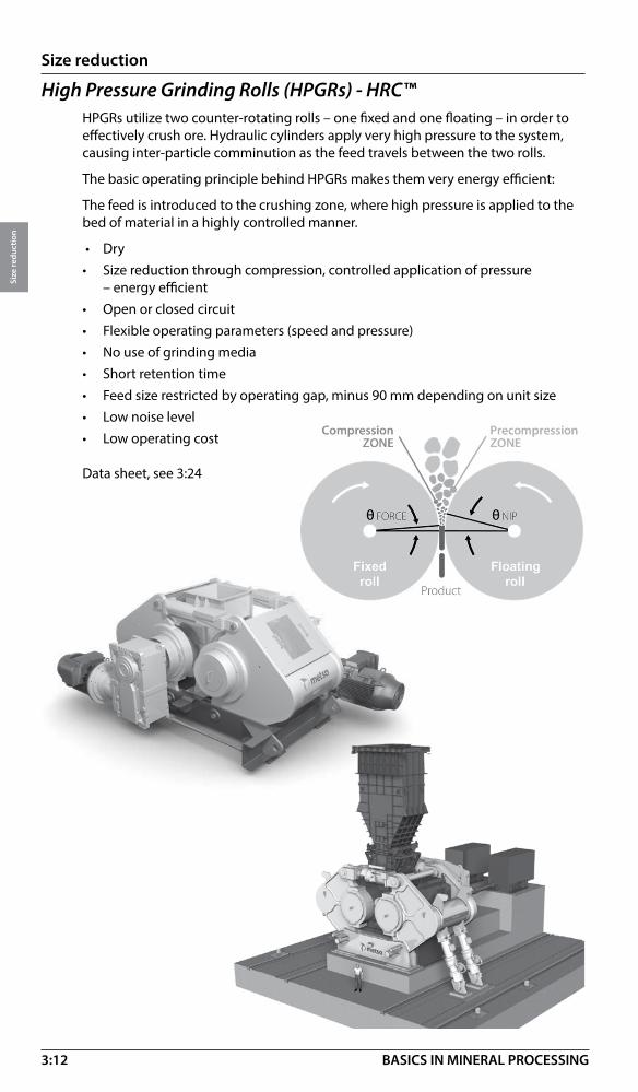
High Pressure Grinding Rolls (HPGRs) - HRC™HPGRs utilize two counter-rotating rolls – one fixed and one floating – in order to effectively crush ore. Hydraulic cylinders apply very high pressure to the system, causing inter-particle comminution as the feed travels between the two rolls.
The basic operating principle behind HPGRs makes them very energy efficient:
The feed is introduced to the crushing zone, where high pressure is applied to the bed of material in a highly controlled manner.
• Dry• Size reduction through compression, controlled application of pressure
– energy efficient• Open or closed circuit• Flexible operating parameters (speed and pressure)• No use of grinding media• Short retention time • Feed size restricted by operating gap, minus 90 mm depending on unit size• Low noise level• Low operating cost
Data sheet, see 3:24

3:13
Size reduction
Size
redu
ctio
n
BASICS IN MINERAL PROCESSING
Tertiary cone crushers – GP* series – Feed size vs capacity
Final crusher – Sizing
VSI crusher – Feed size vs capacity
Data sheet, see 3:22
*Feed top size at minimum setting 10 mm and coarse liner profile
GP550GP330
25 125 250 375 500 625
GP220
Capacity t/h
GP100
Feed top size mm (inch: Divide by 25)
Data sheet, see 3:23
100 200 300 400 500 600 700 800 900 1000
60
50
40
30
20
10
B615
0SE
Capacity t/h
250
200
150
100
Feed top size mm (inch: Divide by 25)
B9100SEB7150SE
HP500
Feed top size mm (inch: divide by 25)
Capacity t/h 100 200 300 400 500 600 700 800
HP300
Data sheet, see 3:19
350
300
200
100
HP200
HP100
HP400
Tertiary cone crushers – HP* series – Feed size vs capacity *Feed top size at 19 mm setting for HP 800

3:14
Size reduction
Size
redu
ctio
n
BASICS IN MINERAL PROCESSING
HPGR - HRC™ 8 - 1450 – Feed size vs capacity
40
30
20
10
0 Capacity t/h
Data sheet, see 3:24
54 80 120 160 200 240 280 320 360 400 440 480 520 560 600 640 680 720 760
HRC™800
HRC™1000 HRC™1200 HRC™1450
Feed top size mm (inch: Divide by 25)
80
70
60
50
40
30
20
10
0 Capacity t/h
Data sheet, 3:24
500 1000 1500 2000 2500 3000 3500 4000 4500 5000 5500 6000 6500
Feed top size mm (inch: Divide by 25)
HPGR - HRC™ 1700 - 3000 – Feed size vs capacity
HRC™ 1700
HRC™2000
HRC™2400
HRC™2600
HRC™3000
HRC™8
Wet crushing prior to grinding*WaterFlush is a patented wet crushing process for producing a flakier finer product from specially designed cone crushers. The method is intended for mining applications comprising secondary crushing, sand manufacturing and fine crushing of ore prior to leaching. The typically crusher discharge is a slurry of 30 to 70% solids. The flakier feed brakes easily in the following grinding mill. WaterFlush can be an alternative to conventional crushing prior to grinding in applications with critical-size-build-up problems in the grinding circuits of type AG/SAG and Pebble mill, see grinding page 3:26-27.
*Not available from Metso
3:15
Size reduction
Size
redu
ctio
n
BASICS IN MINERAL PROCESSING
500 1000 1500 2000 2500 3000 3500 4000 4500 5000 5500 6000 6500
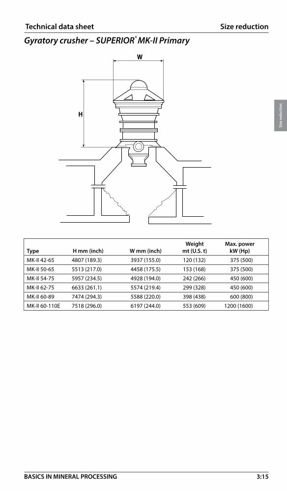
Weight Max. powerType H mm (inch) W mm (inch) mt (U.S. t) kW (Hp)
MK-II 42-65 4807 (189.3) 3937 (155.0) 120 (132) 375 (500)
MK-II 50-65 5513 (217.0) 4458 (175.5) 153 (168) 375 (500)
MK-II 54-75 5957 (234.5) 4928 (194.0) 242 (266) 450 (600)
MK-II 62-75 6633 (261.1) 5574 (219.4) 299 (328) 450 (600)
MK-II 60-89 7474 (294.3) 5588 (220.0) 398 (438) 600 (800)
MK-II 60-110E 7518 (296.0) 6197 (244.0) 553 (609) 1200 (1600)
�
�
SUPERIOR® MK-II Primary Gyratory Crusher
Gyratory crusher – SUPERIOR® MK-II Primary
Technical data sheet

3:16
Size reduction
Size
redu
ctio
n
BASICS IN MINERAL PROCESSING
Technical data sheet
Jaw crusher – C series
� �
�
H L W Weight complete PowerType mm (inch) mm (inch) mm (inch) kg (lbs) kW/Hp
C 80 1700 (67) 2020 (80) 1565 (62) 9520 (21000) 75 (100)
C 96 1930 (76) 2290 (90) 1640 (65) 11870 (26170) 90 (125)
C 106 2400 (95) 2680 (106) 1930 (76) 17050 (37590) 110 (150)
C 116 2650 (104) 2890 (114) 2050 (81) 21500 (47300) 132 (175)
C 120 2950 (116) 3030 (120) 2400 (95) 29300 (64700) 160 (200)
C 130 3330 (131) 3600 (142) 2740 (108) 44000 (97000) 160 (250)
C 150 3680 (145) 3950 (156) 2890 (114) 61430 (135200) 200 (300)
C 160 3850 (152) 4200 (165) 3180 (125) 88500 (194700) 250 (350)
C 200 4220 (166) 4870 (192) 3890 (153) 137160 (302440) 400 (500)
*) complete weight including, feed chute, motor base, guards, motor

3:17
Size reduction
Size
redu
ctio
n
BASICS IN MINERAL PROCESSING
Impact crusher – NP series
�
�
�
Technical data sheet
H L W Weight kW/Hp Type mm (inch) mm (inch) mm (inch) mt (US ton) Max. power
NP 1110 2 716 (107) 3 487 (137) 2 106 (83) 8 (9) 250/350
NP13 2 491 (99) 3 974 (157) 2 531 (100) 12 (13) 315/400
NP15 2 676 (106) 4 187 (165) 2 783 (110) 16 (18) 355 (450)
NP20 3 088 (122) 4 766 (188) 3 720 (147) 27 (31) 630 (2x315) / 800 (2x400)
NP 1313 3 405 (134) 3 396 (134) 2 560 (101) 16 (18) 200/250
NP 1415 3 600 (142) 3 395 (134) 2 790 (110) 20 (22) 250/350
NP 1620 4 400 (173) 3 935 (155) 3 600 (142) 36 (40) 315/400
NP 2023 5 700 (224) 5 040 (198) 4 330 (171) 67 (74) 630 (2x315)/800 (2x400)
3:18
Size reduction
Size
redu
ctio
n
BASICS IN MINERAL PROCESSING
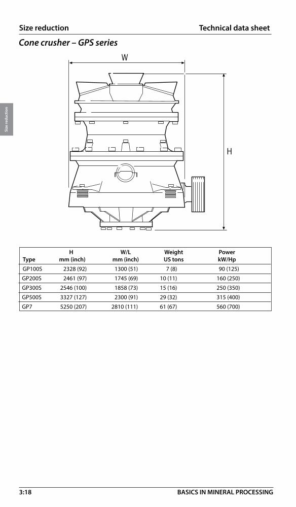
Technical data sheet
Cone crusher – GPS series
�
�
H W/L Weight Power Type mm (inch) mm (inch) US tons kW/Hp
GP100S 2328 (92) 1300 (51) 7 (8) 90 (125)
GP200S 2461 (97) 1745 (69) 10 (11) 160 (250)
GP300S 2546 (100) 1858 (73) 15 (16) 250 (350)
GP500S 3327 (127) 2300 (91) 29 (32) 315 (400)
GP7 5250 (207) 2810 (111) 61 (67) 560 (700)
3:19
Size reduction
Size
redu
ctio
n
BASICS IN MINERAL PROCESSING
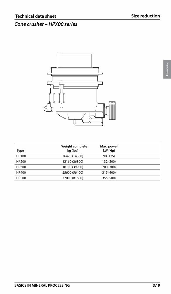
Cone crusher – HPX00 seriesTechnical data sheet
Weight complete Max. powerType kg (lbs) kW (Hp)
HP100 36470 (14300) 90 (125)
HP200 12160 (26800) 132 (200)
HP300 18100 (39900) 200 (300)
HP400 25600 (56400) 315 (400)
HP500 37000 (81600) 355 (500)

3:20
Size reduction
Size
redu
ctio
n
BASICS IN MINERAL PROCESSING
Cone crusher – HPX series
H W Complete* crusher weight Max. powerType mm (inch mm (inch kg (lb) kW (hp)
HP3 2 817 (111) 2 778 (109) 16 100 (35 600) 220 (300)
HP4 3 147 (124) 2 955 (116) 24 200 (53 400) 315 (400)
HP5 3 295 (130) 3 438 (135) 29 000 (64 000) 370 (500)
HP6 3 953 (156) 3 854 (152) 44 500 (98 200) 450 (600)
* Complete crusher weight: crusher + subframe, motor, sub frame, covers, feed and discharge arrangement
W
H
H
W
Cone crusher HP 3 series
Cone crusher HP 4, 5 and 6 series
Technical data sheet
3:21
Size reduction
Size
redu
ctio
n
BASICS IN MINERAL PROCESSING
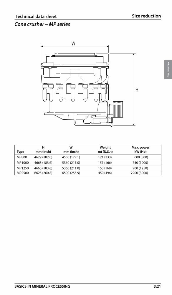
Cone crusher – MP seriesTechnical data sheet
�
�
H W Weight Max. powerType mm (inch) mm (inch) mt (U.S. t) kW (Hp)
MP800 4622 (182.0) 4550 (179.1) 121 (133) 600 (800)
MP1000 4663 (183.6) 5360 (211.0) 151 (166) 750 (1000)
MP1250 4663 (183.6) 5360 (211.0) 153 (168) 900 (1250)MP2500 6625 (260.8) 6500 (255.9) 450 (496) 2200 (3000)
3:22
Size reduction
Size
redu
ctio
n
BASICS IN MINERAL PROCESSING
Technical data sheet
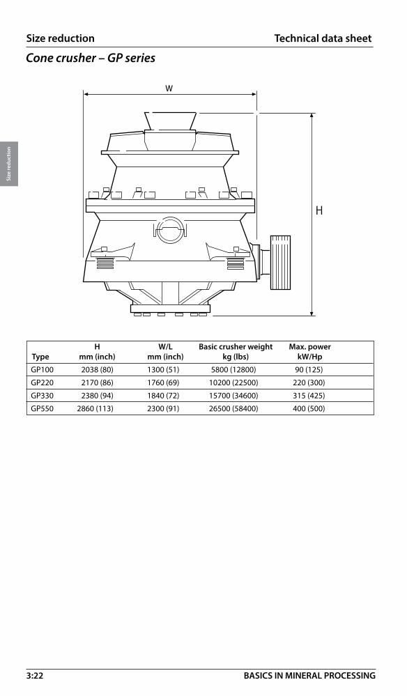
Cone crusher – GP series
�
�
H W/L Basic crusher weight Max. power Type mm (inch) mm (inch) kg (lbs) kW/Hp
GP100 2038 (80) 1300 (51) 5800 (12800) 90 (125)
GP220 2170 (86) 1760 (69) 10200 (22500) 220 (300)
GP330 2380 (94) 1840 (72) 15700 (34600) 315 (425)
GP550 2860 (113) 2300 (91) 26500 (58400) 400 (500)
3:23
Size reduction
Size
redu
ctio
n
BASICS IN MINERAL PROCESSING
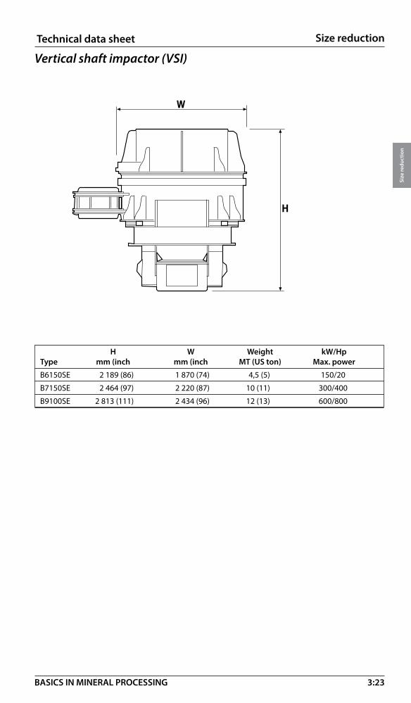
Technical data sheet
H W Weight kW/Hp Type mm (inch mm (inch MT (US ton) Max. power
B6150SE 2 189 (86) 1 870 (74) 4,5 (5) 150/20
B7150SE 2 464 (97) 2 220 (87) 10 (11) 300/400
B9100SE 2 813 (111) 2 434 (96) 12 (13) 600/800
Vertical shaft impactor (VSI)
�
�

3:24
Size reduction
Size
redu
ctio
n
BASICS IN MINERAL PROCESSING
High Pressure Grinding Rolls (HPGRs) - HRC™
Tire Max. motor Max. motor dimensions power power H L WModel mm kW HP mm (inch) mm (inch) mm (inch)
HRC™1200 1200 x 750 2 x 440 kW 2 x 590 HP 2200 (87) 1610 (639) 4400 (173)
HRC™1450 1450 x 900 2 x 650 kW 2 x 872 HP 3556 (140) 2050 (81) 5196 (205)
HRC™1700 1700 x 1000 2 x 900 kW 2 x 1207 HP 3730 (147) 3690 (145) 6240 (246)
HRC™2000 2000 x 1650 2 x 2300 kW 2 x 3084 HP 5309 (209) 6079 (239) 9512 (375)
HRC™2400 2400 x 1650 2 x 3000 kW 2 x 4023 HP 6646 (262) 3630 (143) 9092 (358)
HRC™2600 2600 x 1750 2 x 3700 kW 2 x 4962 HP 6030 (237) 5660 (223) 9380 (369)
HRC™3000 3000 x 2000 2 x 5700 kW 2 x 7644 HP 6937 (273) 6480 (255) 10800 (425)
Tire Max. motor Max. motor dimensions power power H L WModel mm kW HP mm (inch) mm (inch) mm (inch)
HRC™800 730 x 500 2 x 132 kW 2 x 177 HP 2400 (94) 3700 (146) 2700 (106)
HRC™1000 1000 x 625 2 x 260 kW 2 x 349 HP 2700 (106) 3520 (139) 3500 (138)
Technical data sheet
H
W
L
Tire Max. motor Max. motor dimensions power power H L WModel mm kW HP mm (inch) mm (inch) mm (inch)
HRC™8 800 x 500 2 x 75 kW 2 x 100 HP 1630 (64) 2808 (111) 3865 (152)

3:25
Size reduction
Size
redu
ctio
n
BASICS IN MINERAL PROCESSING
Grinding – IntroductionSize reduction by crushing has a size limitation for the final products. If we require further reduction, say below 5-20 mm, we have to use the processes of grinding.Grinding is a powdering or pulverizing process using the rock mechanical forces of impaction, compression, shearing and attrition.The two main purposes for a grinding process are:
• To liberate individual minerals trapped in rock crystals (ores) and thereby open up for a subsequent enrichment in the form of separation.
• To produce fines (or filler) from mineral fractions by increasing the specific surface.
Grinding methods
Grinding mills – Reduction ratiosAll crushers including impactors have limited reduction ratios. Due to the design there is a restricting in retention time for the material passing.
In grinding as it takes place in more “open” space, the retention time is longer and can easily be adjusted during operation. Below the theoretical size reduction and power ranges for different grinding mills are shown. In practise also size reduction by grinding is done in optimised stages.
1 m 100 mm 10 mm 1 mm 100 micron 10 micron 1 micron
AG (kw 15-13 000)
ROD (kw 3-1500)50 mm (2”) 600 microns
BALL (kw 1.5-10 500)15 mm (0.6”)
VERTIMILL® (kw 10-3355)6 mm (3 mesh)
VIBRATING (kw 10-75)6 mm (3 mesh) 45 microns
STIRRED MILL (kw 18.5-1100)1 mm 2 microns
dry/wet
dry/wet
dry/wet
dry
SAG (kw 15-20 000)400 mm (16”)
400 mm (16”) 75 microns
dry/wet
dry/wet75 microns
20 microns
5 microns
by tumbling by stirring by vibration
HPGR HRC™ (kw 150-11 400)90 mm (3.5”)
dry500 microns

3:26
Size reduction
Size
redu
ctio
n
BASICS IN MINERAL PROCESSING
Grinding – Tumbling mills
Autogenous (AG) mill
• Wet or dry• Primary, coarse grinding (up to 400 mm feed size)• Grinding media is grinding feed• High capacity (short retention time)• Sensitive to feed composition (critical size material),
Data sheet 3:44
Semi – Autogenous (SAG) mill
• Wet or dry• Higher capacity than A-G mill grinding• Primary, coarse grinding (up to 400 mm feed size)• Grinding media is grinding feed plus 4-18% ball charge (ball dia.100-125 mm)• High capacity (short retention time)• Less sensitive to feed composition (critical size material), see data sheet 3:44
Rod mill
• Wet only• Coarse grind• Primary mill at plant capacities of
less than 200t/h• Coarse grinding with top size
control without classification• Narrow particle size distribution
• Mostly dry• Coarse grind and high capacity• Special applications• End discharge: finer product• Centre discharge: rapid flow, less
fines• Narrow particle distribution
Overflow End peripheral discharge Center peripheral discharge
Low L/D
High L/D Low L/D
Note! No grate discharge
High L/D

3:27
Size reduction
Size
redu
ctio
n
BASICS IN MINERAL PROCESSING
Ball mill
Pebble mill• Wet or dry• Always grate discharge• Secondary grinding• Grinding media: – A fraction screened out from feed
– Flint pebbles– Porcelain balls– Al2O3 balls
• Larger than ball mills at same power draw
• Grinding without metallic contamination
• Wet only • Dry or wet• Robust and simple • Discharge end more complicated• Mostly in closed circuit (secondary) • Mostly in closed circuit • Finer grind (longer retention time) (secondary) • Higher risk for over grinding • Coarser grind (shorter retention• Ball charge 35-40% time) • Lower risk for over grinding Data sheet, see 3:45-46 • Can take about 5-10% more ball with correspondingly higher through put
Spherical roller antifriction bearing supported mill• Wet or dry• Overflow or grate discharge• Economic solution • Simple design type trunnion anti-
friction roller bearings and lubrication system
• Smaller capacity• Reliable technology
Data sheet, see 3:47
Overflow Grate discharge
3:28
Size reduction
Size
redu
ctio
n
BASICS IN MINERAL PROCESSING
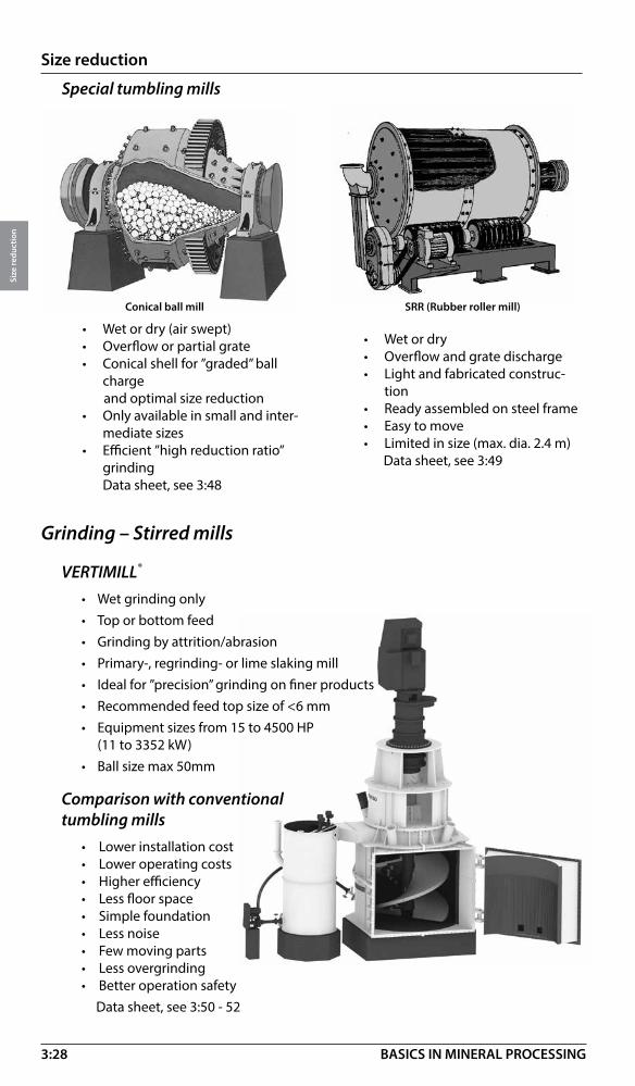
Grinding – Stirred mills
VERTIMILL®
• Wet grinding only• Top or bottom feed• Grinding by attrition/abrasion• Primary-, regrinding- or lime slaking mill• Ideal for ”precision” grinding on finer products• Recommended feed top size of <6 mm• Equipment sizes from 15 to 4500 HP
(11 to 3352 kW)• Ball size max 50mm
Comparison with conventional tumbling mills
• Lower installation cost• Lower operating costs• Higher efficiency• Less floor space• Simple foundation• Less noise• Few moving parts• Less overgrinding• Better operation safety Data sheet, see 3:50 - 52
Special tumbling mills
• Wet or dry• Overflow and grate discharge• Light and fabricated construc-
tion• Ready assembled on steel frame• Easy to move• Limited in size (max. dia. 2.4 m)
Data sheet, see 3:49
• Wet or dry (air swept)• Overflow or partial grate• Conical shell for ”graded” ball
charge and optimal size reduction• Only available in small and inter-
mediate sizes• Efficient ”high reduction ratio”
grinding Data sheet, see 3:48
Conical ball mill SRR (Rubber roller mill)

3:29
Size reduction
Size
redu
ctio
n
BASICS IN MINERAL PROCESSING
Wet grinding only
• Open or closed circuit• Recommended feed size 100 micron and below
• Product size down to 2 micronGrinding media:
Ceramic or Sand Grinding Media, 1-8 mm in diameter
Ceramic media is typically recommended because of lower media consumption,l higher grinding efficiency, and lower wear rates of internal components.
1 Lab Unit, 2 Pilot Units, and 4 full size machines are available (90 kW, 185 kW, 355 kW,and 1100 kW).
Data sheet, see 3:53
Stirred media grinding mIll
Grinding – Vibrating mills
Vibrating ball mill
• Wet or dry
• Impact, shearing and attrition
• Open or closed circuit
• Short retention time - less overgrinding
• Feed size, minus 5 mm
• Limited in size 2x37 kW, 2x50 hp
• High noise level
• Low cost, simple installations
• Low capacity
• Specially applications
Data sheet, see 3:53
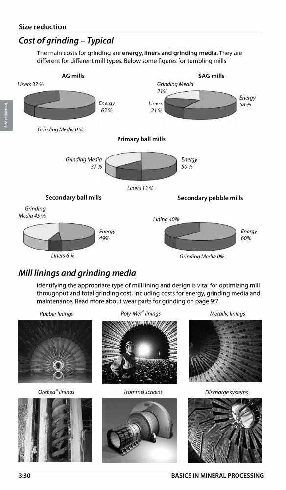
3:30
Size reduction
Size
redu
ctio
n
BASICS IN MINERAL PROCESSING
Secondary ball mills Secondary pebble mills
Primary ball mills
SAG millsAG millsLiners 37 %
Grinding Media 0 %
Liners21 %
Energy58 %
Liners 13 %
Energy50 %
Grinding Media37 %
Liners 6 %
Energy49%
Grinding Media 45 % Lining 40%
Energy60%
Grinding Media 0%
Energy63 %
Cost of grinding – TypicalThe main costs for grinding are energy, liners and grinding media. They are different for different mill types. Below some figures for tumbling mills
Mill linings and grinding mediaIdentifying the appropriate type of mill lining and design is vital for optimizing mill throughput and total grinding cost, including costs for energy, grinding media and maintenance. Read more about wear parts for grinding on page 9:7.
Rubber linings Poly-Met® linings
Orebed® linings Discharge systems
Metallic linings
Trommel screens
Grinding Media 21%

3:31
Size reduction
Size
redu
ctio
n
BASICS IN MINERAL PROCESSING
Grinding circuits
Wet grinding of feed k80 25 - 30 mm (1” - 1 1/4”) to product size k80 0.3 mm to 2 mm (8 Mesh - 48 Mesh) in open circuit.
One of the most common flow-sheets for concentrating plants to wet grind - 25 mm (1”) feeds (or finer) to desired product size. Rod mill discharge ab. 1 mm (16 Mesh).
Grinding mills – SizingEven today this is more of an art than a science. Therefore it should be left to the application offices of your supplier for any valid statements or quotes.
Below will be described some basics of how mills are sized, only.
Fundamental to all mill sizing is determining the necessary specific power consumption for the grinding stage (primary, secondary, tertiary etc.) in question.
It can be established in many ways, some including:
1. Operating data from existing mill circuit (direct proportioning).
2. Grinding tests in pilot scale, where the specific power consumption is determined (kWh/t dry solids).
3. Laboratory tests in small batch mills to determine the specific energy consumption.
4. Energy and power calculations based on Grind Ability Index, for example, Bond work index, (called Wi and normally expressed in kWh/ short ton), see 3:40.
5. Population balance modeling and other simulation techniques
Scale-up criterion is the net specific power consumption, i.e. the power consumed by the mill rotor itself minus all mechanical and electrical losses divided by the feed rate of solids. For the full scale mill this is then to be multiplied by the feed rate to get the net mill power. This must then be increased by the anticipated mechanical inefficiencies (trunnion and pinion bearing friction, ring gear/pinion friction and possible speed reducer losses) as well as electrical losses, in order to arrive at the gross power.
In our labs we can run tests batchwise (in kg scale), or for more critical applications in pilot scale (200-1000 kg/h). The pilot tests are more accurate, but also more expensive.
For all AG or SAG installations such tests are mandatory, since they will tell whether this type of grinding is possible at all, as well as establishing the necessary specific power consumption.
Rod
Rod Ball

3:32
Size reduction
Size
redu
ctio
n
BASICS IN MINERAL PROCESSING
Typical duties: (Single stage ball grinding and single classification circuit)
The most simple and common (although not the most efficient) circuit to wet grind from max. feed sizes of k80 15 mm (5/8”) and finer to required product sizes. Tend to produce more slimes than multistage grinds and classifying.
Typical duties: 1. Autogenous-Single stageFor the rare cases where primary AG milling will inherently produce the required product size. (Wet or dry)
Typical duties: 2. Autogenous + CrusherFor the also not too common cases where critical size pebbles are created and thus inefficient grinding results. With pebble ports in the mill grate and separate crushing of the critical sizes this can be remedied. However, resulting product size must match product requirements. (Wet or dry)
To process
To process

3:33
Size reduction
Size
redu
ctio
n
BASICS IN MINERAL PROCESSING
Typical duties: 3. Autogenous + Ball mill + CrusherThis is also called ”ABC-circuit” and has a ball mill added in comparision with the above circuit No 2. This can be used to correct a too coarse product from the primary mill, and in this way be more useful and common. Mostly operated wet, but also dry possible.
Typical duties: 4. Autogenous + Pebble millTwo stage AG-grinding with the primary mill in open circuit and the secondary pebble mill in closed circuit. The pebble mill gets competent pebbles screened out from the primary mill discharge as needed (or otherwise recirculated to the primary mill). Frequently used by the Boliden mines.
Typical duties: 5. Autogenous + Ball mill / VertiMillSame as the above, but with the pebble mill replaced by a ball mill or a Vertimill. This is used when there is not enough pebbles available in the circuit, or all autogenous grinding produces too much fines.
To process
To process
To process
To process
1. 2.

3:34
Size reduction
Size
redu
ctio
n
BASICS IN MINERAL PROCESSING
Typical duties: 7. Semi-autogenous-Single stageSame as No.1 above, but with the mill as semi-autogenous. This will increase capacity as well as application range, but will also increase wear costs (balls and lining) and still be dependent on ”natural” product size being close to the desired. Common circuit in the US and Canada.
Typical duties: 6. Semi-autogenous + Ball mill / VertiMill
Same as the above No. 5, but with the primary mill as semi-autogenous, which in most cases means higher capacity for the circuit. Many circuits type No. 5 in the US / Canada have been converted to this circuit.
To process To process
1. 2.
To process
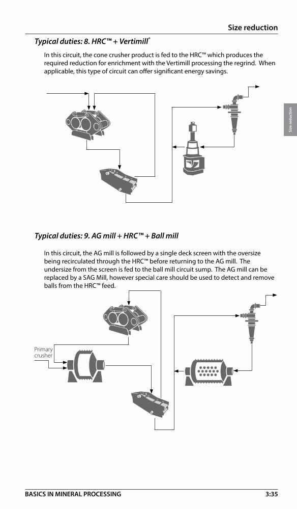
3:35
Size reduction
Size
redu
ctio
n
BASICS IN MINERAL PROCESSING
In this circuit, the cone crusher product is fed to the HRC™ which produces the required reduction for enrichment with the Vertimill processing the regrind. When applicable, this type of circuit can offer significant energy savings.
Typical duties: 8. HRC™ + Vertimill®
In this circuit, the AG mill is followed by a single deck screen with the oversize being recirculated through the HRC™ before returning to the AG mill. The undersize from the screen is fed to the ball mill circuit sump. The AG mill can be replaced by a SAG Mill, however special care should be used to detect and remove balls from the HRC™ feed.
Primary crusher
Typical duties: 9. AG mill + HRC™ + Ball mill

3:36
Size reduction
Size
redu
ctio
n
BASICS IN MINERAL PROCESSING
VERTIMILL® Circuits
Typical duties: 10. Reversed closed circuitScalped or fresh feed directly into the millIf it is desirable to use cyclones, the next decision is where in the process the cyclones should be – either closed circuit or reversed closed circuit. Typical closed circuit has the feed to the Vertimill circuit coming directly to the mill. This means that every particle regardless of size will enter the mill and may be ground. For reverse close circuit, the feed to the Vertimill circuit is introduced at the cyclone sump. The material feeding the circuit that is already at product size will have a chance to bypass the Vertimill all together, and the grinding energy will only be spent on the coarse material. This can reduce the size (and capital cost) of the Vertimill installation.
Mineralogically, there may be some benefit to direct feed in that flotation recovery may improve if all the particles surfaces, regardless of the particle size, are polished or refreshed. The reversed arrangement will minimize fines generation, which may also improve recovery. To best make a mineralogical decision, you need to have a good understand on where the losses are in the flotation circuit.
From a circuit energy perspective, in general, if the feed has very little material (<10%) that is final product size, it is better to feed it directly to the mill because the cyclone or other classifying device will send it all back to the Vertimill anyway and you would be putting undue load on the cyclone feed pumps. If there is a fair amount of fines and the classification is reasonable efficient, pre-classifying the material is beneficial.
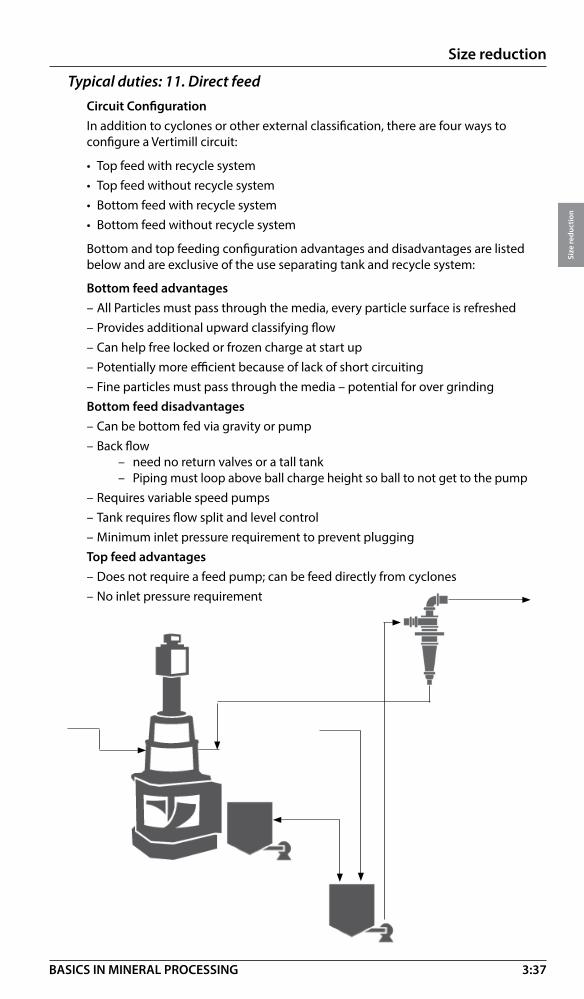
3:37
Size reduction
Size
redu
ctio
n
BASICS IN MINERAL PROCESSING
Typical duties: 11. Direct feedCircuit ConfigurationIn addition to cyclones or other external classification, there are four ways to configure a Vertimill circuit:
• Top feed with recycle system• Top feed without recycle system• Bottom feed with recycle system• Bottom feed without recycle system
Bottom and top feeding configuration advantages and disadvantages are listed below and are exclusive of the use separating tank and recycle system:
Bottom feed advantages– All Particles must pass through the media, every particle surface is refreshed– Provides additional upward classifying flow– Can help free locked or frozen charge at start up– Potentially more efficient because of lack of short circuiting– Fine particles must pass through the media – potential for over grindingBottom feed disadvantages– Can be bottom fed via gravity or pump– Back flow – need no return valves or a tall tank – Piping must loop above ball charge height so ball to not get to the pump– Requires variable speed pumps– Tank requires flow split and level control– Minimum inlet pressure requirement to prevent pluggingTop feed advantages– Does not require a feed pump; can be feed directly from cyclones– No inlet pressure requirement

3:38
Size reduction
Size
redu
ctio
n
BASICS IN MINERAL PROCESSING
Typical duties: 13. Open circuit, scalped feedIf the losses in the flotation circuit are in the coarse, un-liberated material and fines generation needs to be minimized, then the SMD will be most efficient at increasing the recovery by grinding just the coarse material. Scalping cyclones can be used ahead of the mill to scalp the fines and send them straight to the next process, and the cyclone under flow feeds the SMD, and is then recombined with the cyclone overflow for the next process.
As previously stated, the SMD is best operated between 40-50% solids, and a scalping cyclone also provides a nice solution to thicken the feed to the mill.
Stirred Media Detritors (SMD) Circuits
Typical duties: 12. Open circuit, whole feedSMDs already utilize inert grinding media to improve flotation recovery, but the surface preparation of the particle may also be important for the flotation response. The whole stream can be fed direct to the mills in open circuit so that all of the material gets some grinding to prepare the surface for flotation.
If the upstream process can provide steady feed rate and solids concentration (i.e. a thickener), the SMD can be operated in open circuit with no additional equipment required. If the feed rate or solids concentration will fluctuate periodically, then including a buffer tank to feed the mills is advised.
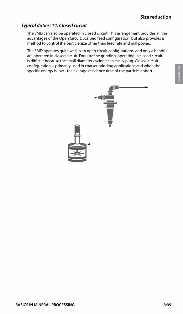
3:39
Size reduction
Size
redu
ctio
n
BASICS IN MINERAL PROCESSING
Typical duties: 14. Closed circuitThe SMD can also be operated in closed circuit. This arrangement provides all the advantages of the Open Circuit, Scalped feed configuration, but also provides a method to control the particle size other than feed rate and mill power..
The SMD operates quite well in an open circuit configurations, and only a handful are operated in closed circuit. For ultrafine grinding, operating in closed circuit is difficult because the small diameter cyclone can easily plug. Closed circuit configuration is primarily used in coarser grinding applications and when the specific energy is low - the average residence time of the particle is short.
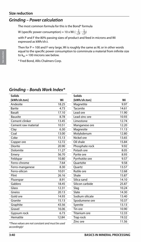
3:40
Size reduction
Size
redu
ctio
n
BASICS IN MINERAL PROCESSING
Grinding – Power calculationThe most common formula for this is the Bond* formula
W (specific power consumption) = 10 x Wi ( )
with P and F the 80% passing sizes of product and feed in microns and Wi expressed as kWh/sh.t.
Then for P = 100 and F very large, Wi is roughly the same as W, or in other words equal to the specific power consumption to comminute a material from infinite size to k80 = 100 microns see below.
* Fred Bond, Allis Chalmers Corp.
Grinding – Bonds Work Index*Solids [kWh/sh.ton] WiAndesite 18.25Barite 4.73Basalt 17.10Bauxite 8.78Cement clinker 13.45Cement raw material 10.51Clay 6.30Coal 13.00Coke 15.13Copper ore 12.72Diorite 20.90Dolomite 11.27Emery 56.70Feldspar 10.80Ferro-chrome 7.64Ferro-manganese 8.30Ferro-silicon 10.01Flint 26.16Fluorspar 8.91Gabbro 18.45Glass 12.31Gneiss 20.13Gold ore 14.93Granite 15.13Graphite 43.56Gravel 16.06Gypsum rock 6.73Hematite 12.84
Solids [kWh/sh.ton] WiMagnetite 9.97Taconite 14.61Lead ore 11.90Lead-zinc ore 10.93Limestone 12.74Manganese ore 12.20Magnesite 11.13Molybdenum 12.80Nickel ore 13.65Oil shale 15.84Phosphate rock 9.92Potash ore 8.05Pyrite ore 8.93Pyrrhotite ore 9.57Quartzite 9.58Quartz 13.57Rutile ore 12.68Shale 15.87Silica sand 14.10Silicon carbide 25.87Slag 10.24Slate 14.30Sodium silicate 13.40Spodumene ore 10.37Syenite 13.13Tin ore 10.90Titanium ore 12.33Trap rock 19.32Zinc ore 11.56
*These values are not constant and must be used accordingly!
� ���� ���

3:41
Size reduction
Size
redu
ctio
n
BASICS IN MINERAL PROCESSING
Pulverizing of coalCoal pulverizing is an important application for grinding mills (ball mill type) and the advantages of using tumbling grinding are many.
Pulverized coal to burners
• Wear on media and linings is low
• High availability (above 95%)
• Constant capacity
• Large reserve capacity
• Abrasive fuels – no problem
• Drying and pulverization in one step
• Efficient blending
Raw coal feedRaw coal feed
Typical capacities (feed moisture 8%)
Mill size m ft Coal flow (mtph) Motor power kW/hp3.8x5.8 12.5x19 42 820/1 1004.0x6.1 13x20 50 969/1 3004.3x6.4 14x21 62 1193/1 6004.7x7.0 15.5x23 82 1640/2 2005.0x7.7 16.5x25 110 2237/3 0005.5x8.2 18x27 141 2760/3 700
Double ended, air-swept ball mill system

3:42
Size reduction
Size
redu
ctio
n
BASICS IN MINERAL PROCESSING
VERTIMILL® – More than a grinding millThe VERTIMILL® grinding mill is considered to be an “intelligent” grinding concept giving an energy saving and controlled process of size reduction. For comparison with tumbling mills, see 3:26.
Mineral applications• Fine / Ultra fine grinding
• Primary grinding
• Secondary grinding
• Tertiary grinding
• “In circuit” regrinding of concentrates
FGD applications• Fine grinding of lime stone
• Lime slaking, see next page
Fuel preparation• Clean coal
• Coal / water
• Coal / oil
Motor
Gear reducer
Reducer pedestal
Feed chute
Separating tank
Dart valve operator
Recycle hose
Recycle pump
Drain Product elbow
Low speed coupling
Thrust bearing
Drive shaft
Upper body
Lower body
Access doorScrew with liners
Magnetic lining
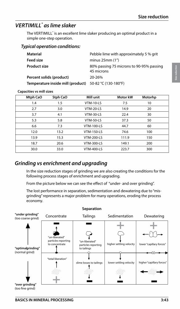
3:43
Size reduction
Size
redu
ctio
n
BASICS IN MINERAL PROCESSING
� � �
�
�
� � �
Grinding vs enrichment and upgradingIn the size reduction stages of grinding we are also creating the conditions for the following process stages of enrichment and upgrading.
From the picture below we can see the effect of “under- and over grinding”.
The lost performance in separation, sedimentation and dewatering due to “mis-grinding” represents a major problem for many operations, eroding the process economy.
“un-liberated”particles reportingto concentrate
“un-liberated”particles reportingto tailings
higher settling velocity lower “capillary forces”
“total liberation”slime losses to tailings lower settling velocity higher “capillary forces”
“under grinding” (too coarse grind)
“optimal grinding”(normal grind)
“over grinding”(too fine grind)
Separation
Concentrate Tailings Sedimentation Dewatering
VERTIMILL® as lime slakerThe VERTIMILL® is an excellent lime slaker producing an optimal product in a simple one-step operation.
Typical operation conditions:Material Pebble lime with approximately 5 % gritFeed size minus 25mm (1”)Product size 80% passing 75 microns to 90-95% passing 45 micronsPercent solids (product) 20-26%Temperature inside mill (product) 50-82 °C (130-180°F)
Capacities vs mill sizes
Mtph CaO Stph CaO Mill unit Motor kW Motorhp
1.4 1.5 VTM-10-LS 7.5 10
2.7 3.0 VTM-20-LS 14.9 20
3.7 4.1 VTM-30-LS 22.4 30
5.3 5.8 VTM-50-LS 37.3 50
6.6 7.3 VTM-100-LS 44.7 60
12.0 13.2 VTM-150-LS 74.6 100
13.9 15.3 VTM-200-LS 111.9 150
18.7 20.6 VTM-300-LS 149.1 200
30.0 33.0 VTM-400-LS 223.7 300
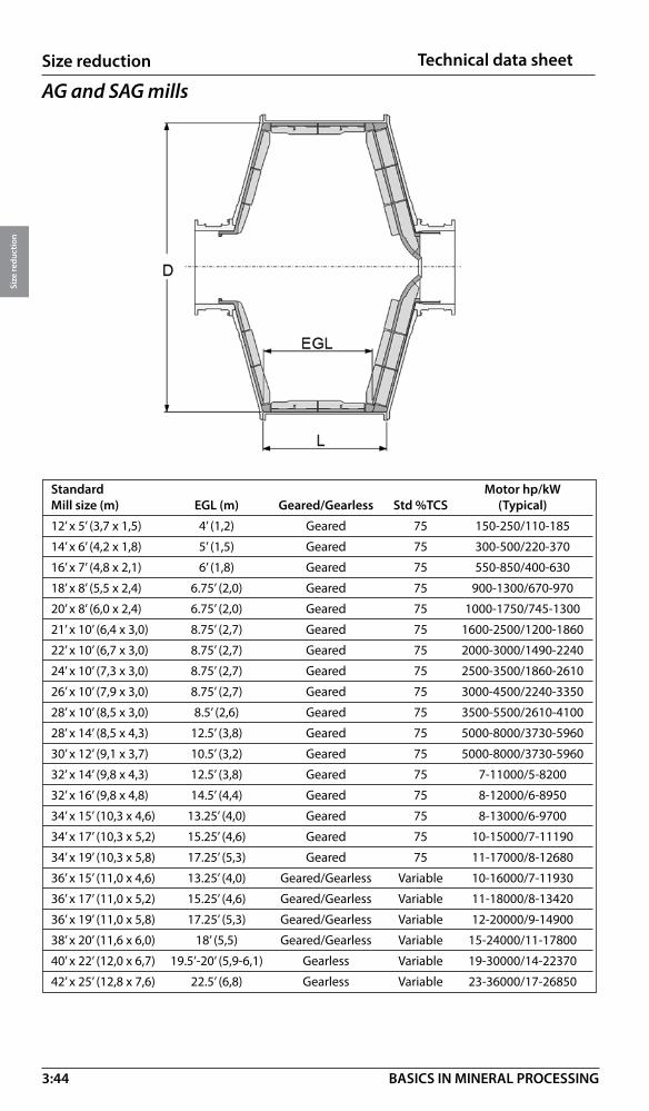
3:44
Size reduction
Size
redu
ctio
n
BASICS IN MINERAL PROCESSING
AG and SAG mills
Technical data sheet
Standard Motor hp/kWMill size (m) EGL (m) Geared/Gearless Std %TCS (Typical)
12’ x 5’ (3,7 x 1,5) 4’ (1,2) Geared 75 150-250/110-185
14’ x 6’ (4,2 x 1,8) 5’ (1,5) Geared 75 300-500/220-370
16’ x 7’ (4,8 x 2,1) 6’ (1,8) Geared 75 550-850/400-630
18’ x 8’ (5,5 x 2,4) 6.75’ (2,0) Geared 75 900-1300/670-970
20’ x 8’ (6,0 x 2,4) 6.75’ (2,0) Geared 75 1000-1750/745-1300
21’ x 10’ (6,4 x 3,0) 8.75’ (2,7) Geared 75 1600-2500/1200-1860
22’ x 10’ (6,7 x 3,0) 8.75’ (2,7) Geared 75 2000-3000/1490-2240
24’ x 10’ (7,3 x 3,0) 8.75’ (2,7) Geared 75 2500-3500/1860-2610
26’ x 10’ (7,9 x 3,0) 8.75’ (2,7) Geared 75 3000-4500/2240-3350
28’ x 10’ (8,5 x 3,0) 8.5’ (2,6) Geared 75 3500-5500/2610-4100
28’ x 14’ (8,5 x 4,3) 12.5’ (3,8) Geared 75 5000-8000/3730-5960
30’ x 12’ (9,1 x 3,7) 10.5’ (3,2) Geared 75 5000-8000/3730-5960
32’ x 14’ (9,8 x 4,3) 12.5’ (3,8) Geared 75 7-11000/5-8200
32’ x 16’ (9,8 x 4,8) 14.5’ (4,4) Geared 75 8-12000/6-8950
34’ x 15’ (10,3 x 4,6) 13.25’ (4,0) Geared 75 8-13000/6-9700
34’ x 17’ (10,3 x 5,2) 15.25’ (4,6) Geared 75 10-15000/7-11190
34’ x 19’ (10,3 x 5,8) 17.25’ (5,3) Geared 75 11-17000/8-12680
36’ x 15’ (11,0 x 4,6) 13.25’ (4,0) Geared/Gearless Variable 10-16000/7-11930
36’ x 17’ (11,0 x 5,2) 15.25’ (4,6) Geared/Gearless Variable 11-18000/8-13420
36’ x 19’ (11,0 x 5,8) 17.25’ (5,3) Geared/Gearless Variable 12-20000/9-14900
38’ x 20’ (11,6 x 6,0) 18’ (5,5) Geared/Gearless Variable 15-24000/11-17800
40’ x 22’ (12,0 x 6,7) 19.5’-20’ (5,9-6,1) Gearless Variable 19-30000/14-22370
42’ x 25’ (12,8 x 7,6) 22.5’ (6,8) Gearless Variable 23-36000/17-26850

3:45
Size reduction
Size
redu
ctio
n
BASICS IN MINERAL PROCESSING
Technical data sheet
Ball mills
Standard Std Approx MotorMill size (m) Geared/Gearless %TCS hp/kW hp/kW
9’ x 12’ (2,7x3,7) Geared 76 388/290 450/335
9’ x 14’ (2,7x4,2) Geared 76 455/340 500/373
9.5’ x 15’ (2,9x4,6) Geared 76 564/420 600/447
10’ x 15’ (3,0x4,6) Geared 76 596/445 700/522
10.5’ x 15’ (3,2x4,6) Geared 76 734/547 800/597
10.5’ x 17’ (3,2x5,2) Geared 76 836/623 900/671
11’ x 17’ (3,3x5,2) Geared 76 944/704 1000/746
11.5’ x 18’ (3,5x5,5) Geared 76 1125/839 1250/932
13’ x 17’ (3,9x5,2) Geared 76 1460/1089 1500/1119
13’ x 19’ (3,9x5,8) Geared 76 1637/1220 1750/1305
14’ x 18’ (4,2x5,5) Geared 76 1877/1400 2000/1491
14’ x 20’ (4,2x6,0) Geared 76 2091/1559 2250/1677
15’ x 19’ (4,6x5,8) Geared 76 2372/1769 2500/1864
15.5’ x 21’ (4,7x6,4) Geared 76 2861/2133 3000/2237
16.5’ x 21’ (5,0x6,4) Geared 76 3362/2507 3000/2237
16.5’ x 24’ (5,0x7,3) Geared 76 3854/2873 4000/2983
16.5’ x 27’ (5,0x8,2) Geared 76 4346/3240 4500/3356
16.5’ x 30’ (5,0x9,1) Geared 76 4838/3608 5000/3728
16.5’ x 33’ (5,0x10,0) Geared 76 5330/3975 5500/4101
18’ x 29’ (5,5x8,8) Geared 76 5847/4360 6000/4474
18’ x 31.5’ (5,5x9,6) Geared 76 6360/4743 6000/4474
18’ x 33.5’ (5,5x10,2) Geared 76 6771/5049 7000/5220
Continues on next page.
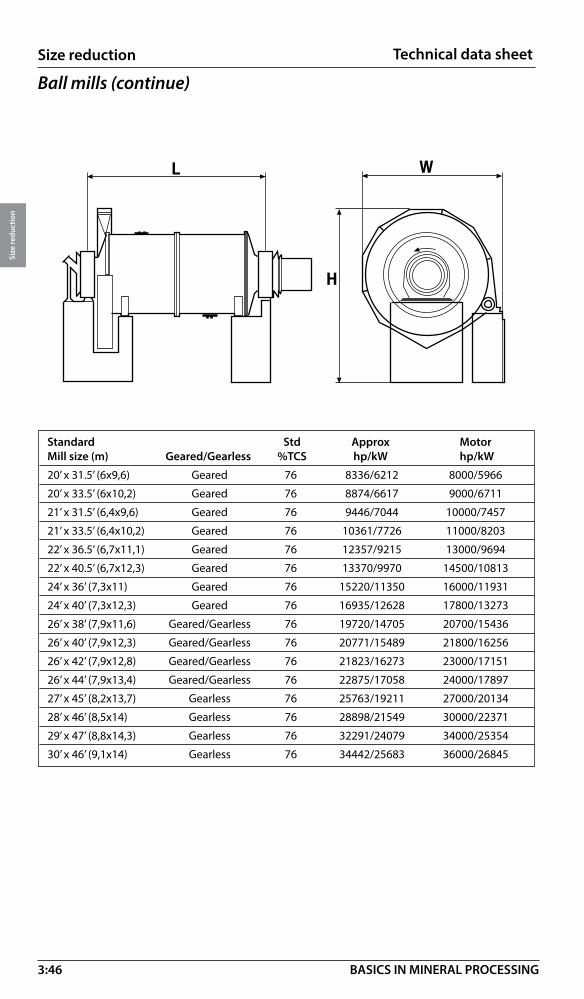
3:46
Size reduction
Size
redu
ctio
n
BASICS IN MINERAL PROCESSING
� �
�
Ball mills (continue)
Standard Std Approx MotorMill size (m) Geared/Gearless %TCS hp/kW hp/kW
20’ x 31.5’ (6x9,6) Geared 76 8336/6212 8000/5966
20’ x 33.5’ (6x10,2) Geared 76 8874/6617 9000/6711
21’ x 31.5’ (6,4x9,6) Geared 76 9446/7044 10000/7457
21’ x 33.5’ (6,4x10,2) Geared 76 10361/7726 11000/8203
22’ x 36.5’ (6,7x11,1) Geared 76 12357/9215 13000/9694
22’ x 40.5’ (6,7x12,3) Geared 76 13370/9970 14500/10813
24’ x 36’ (7,3x11) Geared 76 15220/11350 16000/11931
24’ x 40’ (7,3x12,3) Geared 76 16935/12628 17800/13273
26’ x 38’ (7,9x11,6) Geared/Gearless 76 19720/14705 20700/15436
26’ x 40’ (7,9x12,3) Geared/Gearless 76 20771/15489 21800/16256
26’ x 42’ (7,9x12,8) Geared/Gearless 76 21823/16273 23000/17151
26’ x 44’ (7,9x13,4) Geared/Gearless 76 22875/17058 24000/17897
27’ x 45’ (8,2x13,7) Gearless 76 25763/19211 27000/20134
28’ x 46’ (8,5x14) Gearless 76 28898/21549 30000/22371
29’ x 47’ (8,8x14,3) Gearless 76 32291/24079 34000/25354
30’ x 46’ (9,1x14) Gearless 76 34442/25683 36000/26845
Technical data sheet
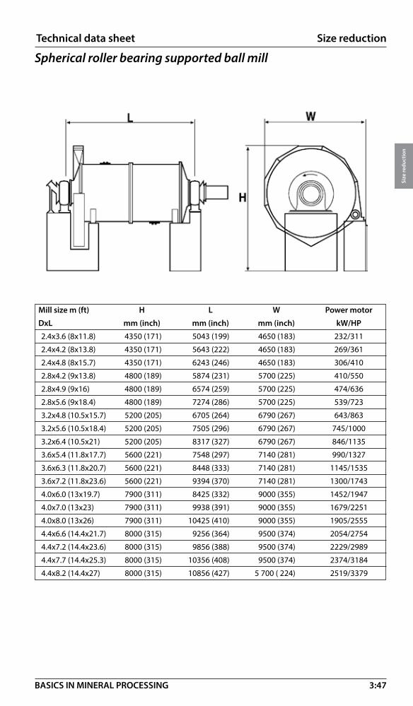
3:47
Size reduction
Size
redu
ctio
n
BASICS IN MINERAL PROCESSING
Spherical roller bearing supported ball mill
Mill size m (ft) H L W Power motor
DxL mm (inch) mm (inch) mm (inch) kW/HP
2.4x3.6 (8x11.8) 4350 (171) 5043 (199) 4650 (183) 232/311
2.4x4.2 (8x13.8) 4350 (171) 5643 (222) 4650 (183) 269/361
2.4x4.8 (8x15.7) 4350 (171) 6243 (246) 4650 (183) 306/410
2.8x4.2 (9x13.8) 4800 (189) 5874 (231) 5700 (225) 410/550
2.8x4.9 (9x16) 4800 (189) 6574 (259) 5700 (225) 474/636
2.8x5.6 (9x18.4) 4800 (189) 7274 (286) 5700 (225) 539/723
3.2x4.8 (10.5x15.7) 5200 (205) 6705 (264) 6790 (267) 643/863
3.2x5.6 (10.5x18.4) 5200 (205) 7505 (296) 6790 (267) 745/1000
3.2x6.4 (10.5x21) 5200 (205) 8317 (327) 6790 (267) 846/1135
3.6x5.4 (11.8x17.7) 5600 (221) 7548 (297) 7140 (281) 990/1327
3.6x6.3 (11.8x20.7) 5600 (221) 8448 (333) 7140 (281) 1145/1535
3.6x7.2 (11.8x23.6) 5600 (221) 9394 (370) 7140 (281) 1300/1743
4.0x6.0 (13x19.7) 7900 (311) 8425 (332) 9000 (355) 1452/1947
4.0x7.0 (13x23) 7900 (311) 9938 (391) 9000 (355) 1679/2251
4.0x8.0 (13x26) 7900 (311) 10425 (410) 9000 (355) 1905/2555
4.4x6.6 (14.4x21.7) 8000 (315) 9256 (364) 9500 (374) 2054/2754
4.4x7.2 (14.4x23.6) 8000 (315) 9856 (388) 9500 (374) 2229/2989
4.4x7.7 (14.4x25.3) 8000 (315) 10356 (408) 9500 (374) 2374/3184
4.4x8.2 (14.4x27) 8000 (315) 10856 (427) 5 700 ( 224) 2519/3379
Technical data sheet

3:48
Size reduction
Size
redu
ctio
n
BASICS IN MINERAL PROCESSING
Conical ball mill
Mill size m (ft) H) L W Power motor
DxL mm (inch mm (inch mm (inch kW/Hp
2.4x0.9 (8x3) 3 350 (132) 3 430 (135) 3 200 (126) 112/150
2.4x1.2 (8x4) 3 350 (132) 3 730 (147) 3 200 (126) 130/175
2.4x1.5 (8x5) 3 350 (132) 4 040 (159) 3 200 (126) 150/200
2.4x1.8 (8x6) 3 350 (132) 4 340 (171) 3 200 (126) 186/250
2.7x1.5 (9x5) 3 960 (156) 4 270 (168) 3 660 (144) 224/300
3.0x1.2 (10x4) 4 360 (168) 3 810 (150) 3 660 (144) 260/350
3.0x 1.7 (10x5.5) 4 360 (168) 4 110 (162) 3 860 (152) 300/400
3.0x1.8 (10x6) 4 360 (168) 4 420 (174) 3 860 (152) 336/450
3.0x2.1 (10x7) 4 360 (168) 4 720 (186) 3 860 (152) 373/500
� �
�
����������������
Technical data sheet

3:49
Size reduction
Size
redu
ctio
n
BASICS IN MINERAL PROCESSING
Technical data sheet
SRR mill
�
�
�
*Dual drive
SRR Ball millMill size m (ft) H L W Power motor Weight (empty)DxL mm (inch) mm (inch) mm (inch) kW/Hp ton
0.6x0.9 (2x3) 1 110 (44) 1 830 (72) 1 220 (48) 2.2/3 0.9
1.0x1.5 (3.3x5) 1 635 (64) 2 700 (106) 1 850 (73) 11/15 2.4
1.2x2.4 (4x8) 1 970 (78) 3 670 (144) 2 740 (108) 30/40 5.6
1.5x3.0 (3.3x6.6) 2 255 (89) 4 550 (179) 3 150 (124) 75/100 9.2
1.8x3.6 (6x12) 2 660 (105) 5 560 (219) 3 500 (138) 132/177 12.8
2.1x3.6 (7x12) 3 150 (124) 5 830 (230) 4 400 (173) 132+75/ 22.0
177+100 *
SRR Rod millMill size m (ft) H L W Power motor Weight (empty)DxL mm (inch) mm (inch mm (inch kW/Hp ton
0.6x0.9 (2x3) 1 110 (44) 1 830 (72) 1 220 (48) 2.2/3 1.0
1.0x1.5 (3.3x5) 1 635 (64) 2 700 (106) 1 850 (73) 11/15 3.0
1.2x2.4 (4x8) 1 970 (78) 3 670 (144) 2 740 (108) 30/40 6.2
1.5x3.0 (3.3x6.6) 2 255 (89) 4 550 (179) 3 150 (124) 75/100 10.0
1.8x3.6 (6x12) 2 790 (110) 5 600 (220) 3 900 (154) 55+55/ 14.5
74+74*

3:50
Size reduction
Size
redu
ctio
n
BASICS IN MINERAL PROCESSING
H L W Power motor Weight (empty)Model mm (inch) mm (inch) mm (inch) kW/Hp ton
VTM-15-WB 7 060 (278) 1 520 (60) 1 320 (52) 11/15 5.5
VTM-20-WB 7 180 (283) 1 520 (60) 1 320 (52) 15/20 5.9
VTM-40-WB 7 460 (294) 1 780 (70) 1 520 (60) 3040 8.2
VTM-60-WB 7 600 (299) 1 780 (70) 1 520 (60) 45/60 8.8
VTM-75-WB 7 900 (311) 1 960 (77) 1 700 (67) 56/75 12.5
VTM-125-WB 9 270 (365) 2 670 (105) 2 310 (91) 93/125 17.9
VTM-150-WB 9 780 (385) 2 670 (105) 2 310 (91) 112/150 19.6
VTM-200-WB 9 780 (385) 2 670 (105) 2 310 (91) 150/200 20.5
VTM-250-WB 9 650 (380) 3 660 (144) 3 180 (125) 186/250 33.8
VTM-300-WB 9 650 (380) 3 660 (144) 3 180 (125) 224/300 35.7
VTM-400-WB 11 320 (446) 3 910 (154) 3 380 (133) 298/400 52.7
VTM-500-WB 12 070 (475) 3 860 (152) 3 780 (149) 373/500 66.1
VERTIMILL®
Type WB (Wet grinding – B design) is larger in diameter, but also have larger diameter, screw turning at lower speed and shorter overall height compared with the LS type. They are designed to operate at full motor power. Orebed lining.
Regarding type LS (Lime Slaking) for size reduction and slaking of lime, see 3:52
SECTION C-C
Technical data sheet
C
SECTION C-C
C
H
W
LC
SECTION C-C
C
H
W
L
H
L
W

3:51
Size reduction
Size
redu
ctio
n
BASICS IN MINERAL PROCESSING
H L W Power motor Weight (empty)Model mm (inch) mm (inch) mm (inch) kW/Hp ton
VTM-650-WB 12 270 (483) 3 250 (128) 3 860 (152) 485/650 82.6
VTM-800-WB 13 460 (530) 3 560 (140) 4 060 (160) 597/800 100.4
VTM-1000-WB 13 460 (530) 3 660 (144) 4 270 (168) 746/1 000 116.1
VTM-1250-WB 13 460 (530) 4 090 (161) 4 520 (178) 932/1 250 125.4
VTM-1500-WB 14 220 (560) 4 370 (172) 4 570 (180) 1 118/1 500 167.0
VTM-3000-WB 17 590 (692) 6 820 (268) 6 880 (271) 2 237/3 000 343.0
VTM-4500-C 18 600 (732) 6 820 (268) 6 880 (271) 3355/4500 367.0
VERTIMILL®
H
W Section C-C
L
c c
Technical data sheet
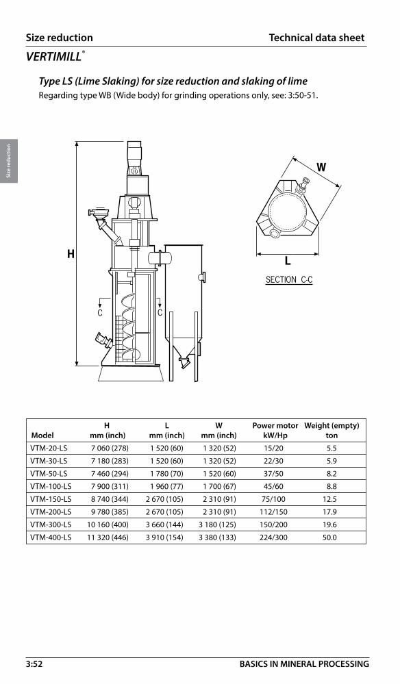
3:52
Size reduction
Size
redu
ctio
n
BASICS IN MINERAL PROCESSING
Technical data sheet
H L W Power motor Weight (empty)Model mm (inch) mm (inch) mm (inch) kW/Hp ton
VTM-20-LS 7 060 (278) 1 520 (60) 1 320 (52) 15/20 5.5
VTM-30-LS 7 180 (283) 1 520 (60) 1 320 (52) 22/30 5.9
VTM-50-LS 7 460 (294) 1 780 (70) 1 520 (60) 37/50 8.2
VTM-100-LS 7 900 (311) 1 960 (77) 1 700 (67) 45/60 8.8
VTM-150-LS 8 740 (344) 2 670 (105) 2 310 (91) 75/100 12.5
VTM-200-LS 9 780 (385) 2 670 (105) 2 310 (91) 112/150 17.9
VTM-300-LS 10 160 (400) 3 660 (144) 3 180 (125) 150/200 19.6
VTM-400-LS 11 320 (446) 3 910 (154) 3 380 (133) 224/300 50.0
VERTIMILL®
Type LS (Lime Slaking) for size reduction and slaking of lime Regarding type WB (Wide body) for grinding operations only, see: 3:50-51.
�
��
������������
� �
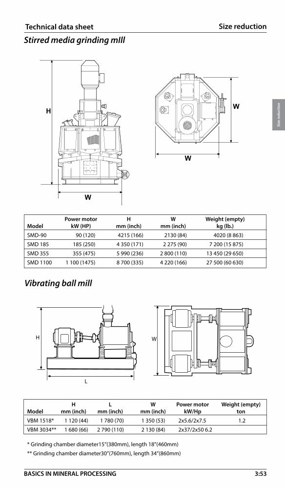
3:53
Size reduction
Size
redu
ctio
n
BASICS IN MINERAL PROCESSING
Stirred media grinding mIll
Power motor H W Weight (empty)Model kW (HP) mm (inch) mm (inch) kg (lb.)
SMD-90 90 (120) 4215 (166) 2130 (84) 4020 (8 863)
SMD 185 185 (250) 4 350 (171) 2 275 (90) 7 200 (15 875)
SMD 355 355 (475) 5 990 (236) 2 800 (110) 13 450 (29 650)
SMD 1100 1 100 (1475) 8 700 (335) 4 220 (166) 27 500 (60 630)
�
�
�
�
Technical data sheet
Vibrating ball mill
�
�
�H
L
W
H L W Power motor Weight (empty) Model mm (inch) mm (inch) mm (inch) kW/Hp ton
VBM 1518* 1 120 (44) 1 780 (70) 1 350 (53) 2x5.6/2x7.5 1.2
VBM 3034** 1 680 (66) 2 790 (110) 2 130 (84) 2x37/2x50 6.2
* Grinding chamber diameter15”(380mm), length 18”(460mm)
** Grinding chamber diameter30”(760mm), length 34”(860mm)
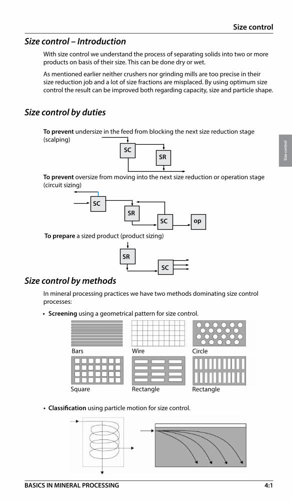
4:1
Size control
Size
con
trol
BASICS IN MINERAL PROCESSING
Size control – IntroductionWith size control we understand the process of separating solids into two or more products on basis of their size. This can be done dry or wet.
As mentioned earlier neither crushers nor grinding mills are too precise in their size reduction job and a lot of size fractions are misplaced. By using optimum size control the result can be improved both regarding capacity, size and particle shape.
Size control by duties
• Classification using particle motion for size control.
Size control by methodsIn mineral processing practices we have two methods dominating size control processes:
• Screening using a geometrical pattern for size control.
To prevent undersize in the feed from blocking the next size reduction stage (scalping)
To prevent oversize from moving into the next size reduction or operation stage (circuit sizing)
To prepare a sized product (product sizing)
SCSR
SC op
SCSR
SR
SC
Bars Wire Circle
Square Rectangle Rectangle

4:2
Size control
Size
con
trol
BASICS IN MINERAL PROCESSING
ScreensPerformance of screens will fall back on three main parameters: Motion – Inclination – Screening media
Screen motions
Screening by stratificationBy building up a material bed on a screen deck the material will stratify when the motion of the screen will reduce the internal friction in the material. This means that the finer particles can pass between the larger ones giving a sharp separation.
Stratification
Separation
Inclined
Circularmotion
Horizontal
Ellipticalmotion
Straightline motion
Horizontal
Straightline throw Inclined
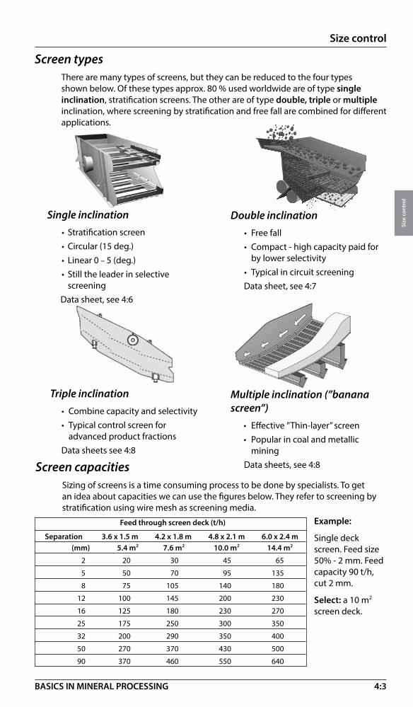
4:3
Size control
Size
con
trol
BASICS IN MINERAL PROCESSING
Single inclination• Stratification screen • Circular (15 deg.)• Linear 0 – 5 (deg.)• Still the leader in selective screeningData sheet, see 4:6
Triple inclination• Combine capacity and selectivity• Typical control screen for advanced product fractions Data sheets see 4:8
Multiple inclination (’’banana screen’’)
• Effective ”Thin-layer” screen• Popular in coal and metallic miningData sheets, see 4:8
Double inclination• Free fall • Compact - high capacity paid for by lower selectivity• Typical in circuit screeningData sheet, see 4:7
Screen types There are many types of screens, but they can be reduced to the four types shown below. Of these types approx. 80 % used worldwide are of type single inclination, stratification screens. The other are of type double, triple or multiple inclination, where screening by stratification and free fall are combined for different applications.
Screen capacities Sizing of screens is a time consuming process to be done by specialists. To get an idea about capacities we can use the figures below. They refer to screening by stratification using wire mesh as screening media.
Feed through screen deck (t/h)
Separation 3.6 x 1.5 m 4.2 x 1.8 m 4.8 x 2.1 m 6.0 x 2.4 m (mm) 5.4 m2 7.6 m2 10.0 m2 14.4 m2
2 20 30 45 65
5 50 70 95 135
8 75 105 140 180
12 100 145 200 230
16 125 180 230 270
25 175 250 300 350
32 200 290 350 400
50 270 370 430 500
90 370 460 550 640
Example:
Single deck screen. Feed size 50% - 2 mm. Feed capacity 90 t/h, cut 2 mm.
Select: a 10 m2 screen deck.
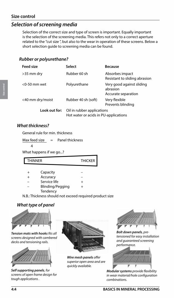
4:4
Size control
Size
con
trol
BASICS IN MINERAL PROCESSING
Rubber or polyurethane?Feed size Select Because
>35 mm dry Rubber 60 sh Absorbes impact Resistant to sliding abrasion <0-50 mm wet Polyurethane Very good against sliding abrasion Accurate separation<40 mm dry/moist Rubber 40 sh (soft) Very flexible Prevents blinding Look out for: Oil in rubber applications Hot water or acids in PU-applications
Selection of screening mediaSelection of the correct size and type of screen is important. Equally important is the selection of the screening media. This refers not only to a correct aperture related to the ”cut size ”, but also to the wear in operation of these screens. Below a short selection guide to screening media can be found.
THINNER THICKER
+ Capacity – + Accuracy – – Service life + – Blinding/Pegging + TendencyN.B.: Thickness should not exceed required product size
What happens if we go...?
General rule for min. thickness
Max feed size = Panel thickness 4
What thickness?
What type of panel
Tension mats with hooks fits all screens designed with cambered decks and tensioning rails.
Bolt down panels, pre-tensioned for easy installation and guaranteed screening performance.
Self supporting panels, for screens of open frame design for tough applications .
Modular systems provide flexibility in wear material/hole configuration combinations.
Wire mesh panels offer superior open area and are quickly available.

4:5
Size control
Size
con
trol
BASICS IN MINERAL PROCESSING
General guideline for wire mesh:
“Required product size plus 5 – 10%”
General guideline for rubber panels:
“Required product size plus 25 – 30%”
General guideline for PU panels:
“Required product size plus 15 – 20%”
What hole size? (Inclined deck)
The standard choice
For improved service life (coarse screening)
For improved capacity
For improved accuracy and dewatering
What type of hole?
mesh* micron mesh micron mesh micron 2½ 8000 14 1180 80 180 3 6700 16 1000 100 150 3½ 5600 20 850 115 125 4 4750 24 710 150 106 5 4000 28 600 170 90 6 3350 32 500 200 75 7 2800 35 425 250 63 8 2360 42 355 270 53 9 2000 48 300 325 45 10 1700 60 250 400 38 12 1400 65 212 500 25
*Taylor serie (US)
Mesh number = the number of wires per inch or the number of square apertures per inch
4000 micron
1 2 3 4 5
1”
Particle size – Mesh or Micron?
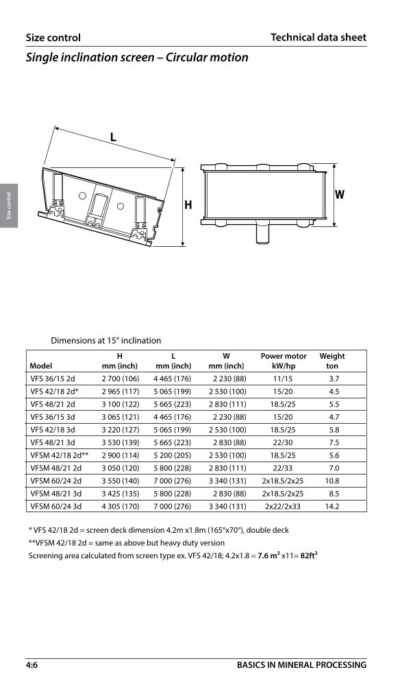
4:6
Size control
Size
con
trol
BASICS IN MINERAL PROCESSING
Technical data sheet
Dimensions at 15° inclination
H L W Power motor Weight Model mm (inch) mm (inch) mm (inch) kW/hp ton
VFS 36/15 2d 2 700 (106) 4 465 (176) 2 230 (88) 11/15 3.7
VFS 42/18 2d* 2 965 (117) 5 065 (199) 2 530 (100) 15/20 4.5
VFS 48/21 2d 3 100 (122) 5 665 (223) 2 830 (111) 18.5/25 5.5
VFS 36/15 3d 3 065 (121) 4 465 (176) 2 230 (88) 15/20 4.7
VFS 42/18 3d 3 220 (127) 5 065 (199) 2 530 (100) 18.5/25 5.8
VFS 48/21 3d 3 530 (139) 5 665 (223) 2 830 (88) 22/30 7.5
VFSM 42/18 2d** 2 900 (114) 5 200 (205) 2 530 (100) 18.5/25 5.6
VFSM 48/21 2d 3 050 (120) 5 800 (228) 2 830 (111) 22/33 7.0
VFSM 60/24 2d 3 550 (140) 7 000 (276) 3 340 (131) 2x18.5/2x25 10.8
VFSM 48/21 3d 3 425 (135) 5 800 (228) 2 830 (88) 2x18.5/2x25 8.5
VFSM 60/24 3d 4 305 (170) 7 000 (276) 3 340 (131) 2x22/2x33 14.2
* VFS 42/18 2d = screen deck dimension 4.2m x1.8m (165“x70“), double deck
**VFSM 42/18 2d = same as above but heavy duty version
Screening area calculated from screen type ex. VFS 42/18; 4.2x1.8 = 7.6 m² x11= 82ft²
Single inclination screen – Circular motion
�
��
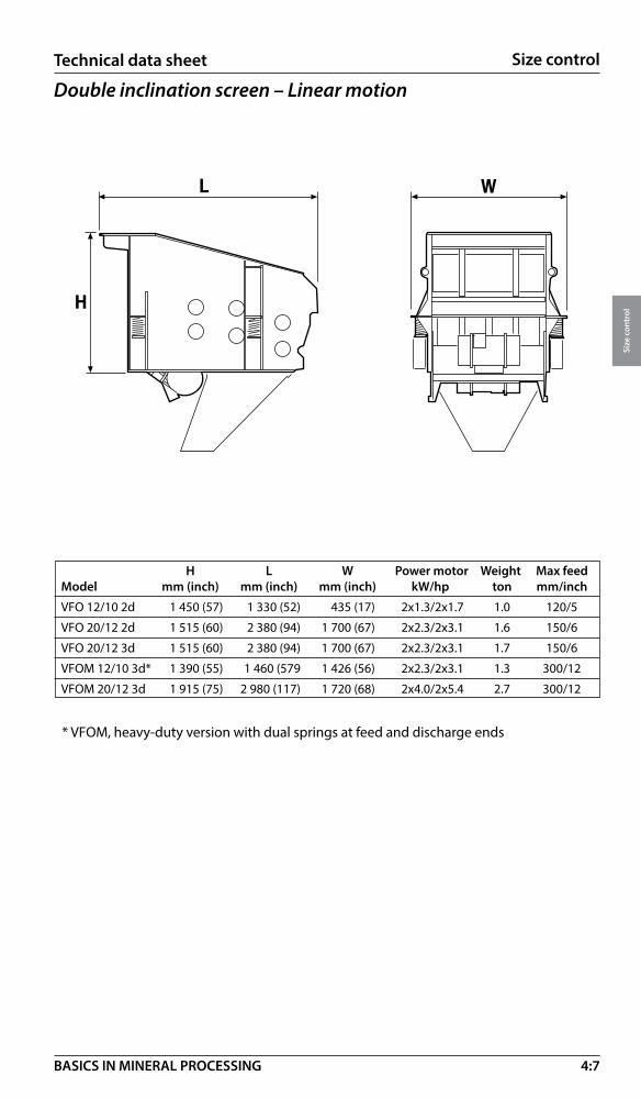
4:7
Size control
Size
con
trol
BASICS IN MINERAL PROCESSING
Technical data sheet Technical data sheet
Double inclination screen – Linear motion
�
�
�
H L W Power motor Weight Max feedModel mm (inch) mm (inch) mm (inch) kW/hp ton mm/inch
VFO 12/10 2d 1 450 (57) 1 330 (52) 435 (17) 2x1.3/2x1.7 1.0 120/5
VFO 20/12 2d 1 515 (60) 2 380 (94) 1 700 (67) 2x2.3/2x3.1 1.6 150/6
VFO 20/12 3d 1 515 (60) 2 380 (94) 1 700 (67) 2x2.3/2x3.1 1.7 150/6
VFOM 12/10 3d* 1 390 (55) 1 460 (579 1 426 (56) 2x2.3/2x3.1 1.3 300/12
VFOM 20/12 3d 1 915 (75) 2 980 (117) 1 720 (68) 2x4.0/2x5.4 2.7 300/12
* VFOM, heavy-duty version with dual springs at feed and discharge ends

4:8
Size control
Size
con
trol
BASICS IN MINERAL PROCESSING
Technical data sheet
Triple inclination screen – Linear motion
Multiple inclination screen – Linear motion (Banana screen)
H L W Power motor Weight Model mm (inch) mm (inch) mm (inch) kW/hp ton
MF 1800x6100 1d 2 703 (107) 6 430 (253) 2 555 (101) 22/30 6.7
MF 2400x6100 1d 2 691 (106) 6 431 (253) 3 166 (125) 30/40 8.5
MF 3000x6100 1d 2 897 (114) 6 614 (260) 3 774 (149) 45/60 11.5
MF 3000x6100 2d 4 347 (171) 6 759 (266) 3 774 (149) 45/60 17.0
� �
�
L W
A
* TS 2.2 = 2 decks and TS 2.3 = 3 decks screen
L W A Power Weight Model mm (inch) mm (inch) m2 (Sq. ft.) motor kW /HP ton
TS 2.2* 5 830 (230) 1 530 (60) 7.5 (80) 15/20 6
TS 2.3* 5 830 (230) 1 530 (60) 7.5 (80) 15/20 8
TS 3.2 6 330 (249) 1 839 (72) 11 (116) 22/30 8
TS 3.3 6 330 (249) 1 839 (72) 11 (116) 22/30 10
TS 4.2 6 350 (250) 2 445 (96) 15 (156) 30/40 9
TS 4.3 6 350 (250) 2 445 (96) 15 (156) 30/40 12
TS 5.2 8 595 (338) 2 445 (96) 20 (215) 30/40 16
TS 5.3 8 595 (338) 2 445 (96) 20 (215) 2x22/2x30 20
TS 6.2 8 734 (344) 3 045 (120) 25 (269) 2x22/2x30 20
TS 6.3 8 736 (344) 3 045 (120) 25 (269) 2x30/2x40 24

4:9
Size control
Size
con
trol
BASICS IN MINERAL PROCESSING
Classification – IntroductionFor size control of particles finer than 1 mm, we are moving out of the practical range of conventional screens.
Classification is the process of separating particles by size into two or more products according to their behavior in air or water (liquids).
Classification methods
• Wet classification with hydrocyclones using separation by centrifugal force covering the size range of 100 –10 micron (typical)
• Wet classification with spiral classifiers using separation by gravity covering the size range of 100 – 1000 micron (typical)
• Dry classification using separation by centrifugal force covering the range of 150 – 5 micron (typical).
Wet classification – fundamentals
If a particle has no interference from other particles it moves faster than a particle surrounded by other particles due to increased density and viscosity of the slurry.This is called free and hindered movement and is valid both for gravity and centrifugal classification.
��
��
�
�
Coarse particles move faster than fine particles at equal density
High density particles move faster than low density particles at equal size
��
��
�
�
Free movement Hindered movement

4:10
Size control
Size
con
trol
BASICS IN MINERAL PROCESSING
Hydrocyclone – Introduction• Feed is pumped tangentially into
the hydrocyclone.• Centrifugal forces classify solids
by mass (size).• Pressure drop within the
hydrocyclone creates an air core in the center.
• High mass particles closer to outer wall report to the underflow.
• Low mass particles closer to the center report to the overflow.
• Apex and Vortex Finder define the size of the air core and, therefore, the size classification
• Classification in grinding circuits • Dewatering and thickening • Desliming and washing
• Classification of multi-component ore• Enrichment of heavy minerals (DMS) • a.o.
Although the hydrocyclone by nature is a size controlling machine the number of applications in mineral are many:
Hydrocyclone applications – more than size control
Feed inlet
Overflow pipe
Vortex finder
Head housings
Head liners
Single componet zoon
Apex housing
Apex
Pump
Overflow
Feed steram
Vortex finder
Apexorifice
Underflow

4:11
Size control
Size
con
trol
BASICS IN MINERAL PROCESSING
Hydrocyclone cluster
Flows processed through a hydrocyclone are wide ranging in particle size distribution, slurry density, volumetric throughput, etc. Because of this, multiple hydrocyclones of a particular model are typically supplied in a larger package called a hydrocyclone cluster or hydrocyclone pack.
This hydrocyclone cluster consists of: individual hydrocyclones, hydrocyclone feed distributor, underflow launder, overflow launder, knife gate valves, and support structure. Working platforms for access are also optional for ease of maintenance tasks.
The hydrocyclone feed distributor can either be a linear or a radial design to evenly distribute feed to each hydrocyclone. A local pressure gauge and pressure transmitter can also be included for process monitoring of the hydrocyclones.
The underflow launder and the overflow launder combine the flows from the multiple hydrocyclones into one stream for each product. In classification of a grinding circuit, underflow may report back to the grinding mill while the overflow leaves the circuit as product.
To maintain high availability, many hydrocyclone clusters are supplied with one or more additional hydrocyclones than required to act in a stand-by capacity. Knife gate valves are installed to isolate each individual hydrocyclone so that maintenance tasks can be completed on stand-by hydrocyclones while the other hydrocyclones are operating.

4:12
Size control
Size
con
trol
BASICS IN MINERAL PROCESSING
A
B
C
Technical data sheet
A B C Nominal Max feed mm (inch) mm (inch) mm (inch) Weight operating slurry flow Cyclone Cyclone body Cyclone body (empty) pressure m3/hr Model height lenght width kg kPa (psi) (gpm)
MHC 100 881 (35) 220 (9) 200 (8) 7 200 (29) 24.7 (108.8)
MHC 150 1 097 (43) 308 (12) 273 (11) 12 150 (22) 47.5 (209.1)
MHC 250 1 841 (72) 580 (23) 498 (20) 125 120 (17) 114.9 (505.9)
MHC 375 2 223 (88) 827 (33) 730 (29) 201 100 (15) 239.8 (1 055.8)
MHC 500 2 626 (103) 1 063 (42) 902 (36) 375 90 (13) 398.1 (1 752.8)
MHC 650 3 295 (130) 1 337 (53) 1 152 (45) 800 80 (12) 759.0 (3 341.8)
MHC 800 2 978 (157) 1 616 (64) 1 349 (53) 1 125 75 (11) 1 171.0 (5 155.8)
Hydrocyclone

4:13
Size control
Size
con
trol
BASICS IN MINERAL PROCESSING
Spiral classifier* By combining a gravity settler of rectangular section with a sloped transport spiral for the sediment – we have a spiral classifier.
Spiral classifier – Nomenclature24” Model 100-MF-SP
Pitch – Single (SP) or Double (DP) Tank Style – Straight (ST), Modified Flare (MF) and Full Flare (FF) Spiral Submergence Model – 100%, 125% or 150% Spiral Diameter
Spiral classifier – DesignBy combining the proper submergence of the spiral as shown in the drawings of the three models at right with one of the three tank designs a choice of combinations are possible. Thus the selection can be tailored to suit each problem. The proper combination of pool depth, area and spiral construction, result in controlled turbulence for accurate size separations or efficient washing or dewatering as desired.
The required pool area is balanced with the sand raking capacity of the spiral by the design of the tank. Tank designs to suit specific applications are shown below.
Straight Modified Full flare side tank flare tank tank design
Straight side: For coarse separations.
Modified flare: Increases pool area for intermediate to fine separations and for washing and dewatering.Full flare: Maximum pool area for fine to very fine separations and for washing and dewatering where large volumes of water are to be handled.Sand raking and conveying is usually a major consideration in any classifier application, and the full range of spiral diameters available cover all requirements. Each of these units is designed for high efficiency and greater raking capability due to the increased lead or helix angle of the spiral. This increased lead angle results in improved conveying efficiency and greater conveying capacity.
100% Spiral submerge
125% Spiral submerge
150% Spiral submerge
Model 100
Model 125
Model 150
Technical data sheet

4:14
Size control
Size
con
trol
BASICS IN MINERAL PROCESSING
Single pitch:
Single pitch spirals are available on all sizes of classifier and consist of one continuous spiral ribbon.
Double pitch:
The double pitch spiral has twice the raking capacity of a single pitch assembly and consists of two duplicate spiral ribbons. This construction is available for all sizes of classifier.
24” 30” 36” 42” 48” 54” 60” 66” 72” 78”
* Contact Metso for further information about this product.
4:15
Size control
Size
con
trol
BASICS IN MINERAL PROCESSING
Dry classification – Introduction
GeneralThe Static and dynamic air classifiers offer solutions in combination with ancillary equipment to meet the demands of almost any dry separation requirement. This equipment offers solutions to the mining, construction, industrial mineral and chemical industries. A wide range of separations are available from 1.4mm (12#) down to 10μm (#1250) with separation efficiencies of up to 95%. Full, flexible engineering design and support is available to ensure full integration.
Classifier throughputs range from lab size units to applications processing hundreds of tones per hour. Application, feed type, fineness of classification and classification accuracy required influence the allowable moisture in the feed which typically ranges from 2.5% to below 1% dependant on the process.
The static and dynamic classifiers offer tailored solutions for a wide range of applications Machine sizing and selection is normally done in consultation with the product line to ensure correct application and matching with required ancillary equipment.
Typical applicationsMining Dry grindingArid zone mining
ConstructionConcrete sandAsphalt sandMineral filler
Industrial Minerals Silicates Graphite Glass Ceramics Salts Feldspar Talc Chalk
Diatomaceous earth Gypsum Betonite
Cement and Pozzolan Fly AshSlag Cement Other pozzolan
Chemical Soda Ash Metallurgical processing additives Cosmetics Stearate (salts) Fertilizer Bicarbonate (FGD)
Static classifiersStatic air classifiers achieve accurate separations from 1.4 mm (12 mesh) to 20μm (635 mesh). The static air classifiers are designed to achieve extremely accurate separations even though they contain no moving elements in the airstream.
This is achieved through airflow design and use of recirculating, secondary airflow on finer separations to scrub the coarse product before it is discharged. The re- cir culating airflow is adjustable so the amount of undersize retained is also adjust-able. This provides fine tuning of the end products so exact product specifications can be achieved. The design of the recirculating systems mean that adjustments can be done during production and results are instant.
The static design of these classifiers offers excellent wear characteristics through the use of ceramic linings whose lifetimes are measured in years, low maintenance requirements and low power draw.

4:16
Size control
Size
con
trol
BASICS IN MINERAL PROCESSING
Gravitational classifiersThe gravitational classifiers are designed for coarser separations in the range of 1.4mm/150µm (12/100#). The feed material is spread over the width of the classi-fier and drops as a continuous feed curtain through the top of the classifier. Low velocity air enters the classifier through the front inlet and is drawn through the feed curtain which is dropping in front of the angled vanes on the air outlet.
The air stream enters the feed curtain perpendicularly and draws the finer particles from the curtain of mate-rial. The air current then draws the particles up almost vertical through the vane rack. Gravitational classifiers are suitable for closing grinding circuits, de-dusting of coarser feeds, reducing a high feed loading rate to a finer classifier and it can also be used as a density separator if the specific gravity difference of the product : waste ratio is > 5:1.
Gravitational inertial classifiersThese units combine gravitational, inertial, centrifugal and aerodynamic forces to achieve separations from 300 μm /63μm (50/230#). The feed material is spread over the width of the classifier and drops as a continuous feed curtain through the top of the classifier. The primary air also enters the top of the classifier in a downward direction with the feed. The air is drawn through the feed curtain and then through a 120° change in direction and exits through the vanes carrying undersize particles with it.
The coarser particles that are not drawn away drop down to where a secondary air flow is drawn into the classifier. The coarse particle curtain is scrubbed by this secondary air with the finer fraction being drawn by the secondary airflow back into the primary feed curtain. By making simple adjustments to the secondary air damper the end products can be modified. As there are no moving parts within the material flow stream significantly reduces maintenance requirements. Use of ceramic lining throughout the classifier gives impressive wear resistance.
Gravitational inertial classifier
Gravitational classifier

4:17
Size control
Size
con
trol
BASICS IN MINERAL PROCESSING
Centrifugal classifiersThe centrifugal classifier utilizes centrifugal forces in a similar way to cyclones to in-duce fine particle separation. The classifier is capable of separations in the range of 100/15μm (140/800#). The classifier has widespread acceptance in industrial miner-als, cement and fly ash applications where its high degree of separation accuracy and exceptionally low maintenance requirements exceeds operator expectations. The classifier is used in conjunction with a dust collector and system fan. Systems can have an open or closed loop dependant on application and numerous dust collector and silo storage options.
Cyclonic ultrafine classifiersSpecially designed high efficiency cyclonic classifiers with controllable reverse air flow systems can achieve adjustable ultrafine classifications. The cyclonic ultra-fine classifier is a hybrid air cyclone that combines cyclone and classifier designs to separate very fine particles. In conventional air cyclones, the aim is to remove as much of the particulate from the airstream as possible. However the cyclonic ultrafine classifier is designed to allow the finest particles to be removed in the ascending vortex.
This separation is achieved by introducing a reverse airflow into the specially designed disengaging hop-per that weakens the descending vortex and creates a stronger entraining force in the ascending vortex that draws the required particles away to the fines collector. Control of the separation point is achieved by varying the percentage of reverse airflow relative to the total air.
The cyclonic ultrafine classifier is designed to achieve separations in the region of 50μm (#270) to 10μm (#1250) with a top feed size of 5mm (#4). The cyclonic ultrafine classifiers are very low maintenance even on highly abrasive feeds. The unit contains no moving parts and adjustments can be made on-line. The range of manufacturing materials available includes abrasion resistant, stainless and mild steels and aluminum. For abrasive applications, ceramic lining is available which give exceptional sliding wear resistance.
Centrifugal classifier, dust collector and fan
Cyclonic ultrafine classifier
4:18
Size control
Size
con
trol
BASICS IN MINERAL PROCESSING
Dynamic classifiersThe dynamic air classifiers are built to suit a range of applications and systems and have been often installed on air swept mills circuits. The gyrotor, a rotating vane air classifier, separates dry, solid, homogenous particles by size. Delta-sizers are designed for accurate separation of dry feeds at high efficiency and low power consumption on a continuous basis.
GyrotorsUtilizes a rotating vane to separate dry solid particles by size for separations for 500/45µm (35/325 mesh). Gyrotors can be integrated into a conventional closed or open dry grinding circuit. Gyrotors can also be utilized in a classifi-cation only system complete with cyclone, fan, dust collec-tor and rotary air locks.
Delta-sizersDelta-sizers are designed for accurate separation of dry feeds at high efficiency and low power consump-tion on a continuous basis. The Metso Delta-sizer can be integrated into a conventional closed or open dry grinding circuit; or utilized in a classification only system complete with cyclone, fan, dust collector and rotary air locks.
Ancillary air solutions Ancillary air solutions provide the systems required for the correct operation of the classifier equipment as well as offering other dry solution capabilities.
High efficiency cyclonesHigh efficiency cyclone technologies are specifically tai-lored to the needs of the mining, industrial mineral and construction industries.
The high efficiency cyclones are the product of signi-ficant development with the aim of achieving extremely high levels of particle removal from the airstream. The unique inlet scroll is designed with a smooth flow elbow to eliminate currents perpendicular to the main direc-tion of gas flow that is present in standard conventional rectangular entrance cyclones.
Custom designed disengaging hoppers give high efficient separations by creating a void that hosts the bottom section of the descending vortex and allows the particles to disengage from the airstream before it ascends the gas outlet tube.
Gyrotor
Delta-sizer
High efficiency cyclone

4:19
Size control
Size
con
trol
BASICS IN MINERAL PROCESSING
Multi-stage fluid bed coolersDirect particle cooling and cleaning technologies are designed to process granular feeds. Multi-stage fluid bed coolers have been developed to offer simple practical solutions for cooling and cleaning granular feeds. These coolers are designed to work in conjunc-tion with a dust collector and system fan to create a drop in pressure that draws in atmospheric air.
The feed enters the cooler through an airlock and is then evenly distributed onto the first perforated plate tray. Each tray has specifically designed apertures and is individually vibrated by an electric activator mounted above the plate. The rising airflow passes through the tray apertures and creates a fluidized bed of particles whilst carrying the ultrafine particles away to the dust collector. The fluidized bed dictates the particles residence time before dropping down to the next level plate. The individual particles eventually pass into the collection hopper where they exit the cooler through the sample valve airlock.
Smart package dust collectorsTo fully support the classification solutions offering, the ancillary equipment requirement must be considered.
To fully support this offering, the ancillary equipment requirement must be consid-ered. The smart package was developed to offer a quality dust collecting solution without unnecessary transportation costs while ensuring quality solutions. Dust collectors tend to be large, bulky pieces of equipment that are expensive to trans-port due to their significant volume. The smart package is designed as an easily transportable solution that offers a simple, local manufacturing solution to customers requiring pulse jet dust collec-tors. The smart package consists of the tube sheet, solenoids, pulse pipes and
air manifold. The Smart Package is supplied with Metso’s pulse jet dust collector engineering design to ensure success-ful installation. Smart package designs are available to meet the capacity requirements of the air classifier range and are also suitable for other dust collection duties.
The smart package dust collector. Close up of the smart package tube sheet, solenoids, pulse pipes and air manifold.
Multi-stage fluid bed cooler

4:20
Size control
Size
con
trol
BASICS IN MINERAL PROCESSING
Grate discharge mill in closed circuit with a Gravitational Inertial classifier producing products in the range of 300/63µm (#50/230)
Air swept mill feeding a cyclone disengaging the throughput into Centrifugal classifier with the oversize returning to the mill and producing products in the range of 100/20µm (#140/635)
System fan
Dust collector
Productsilo
Gravitational inertial
classifier Bucket elevator
Bucket elevator
Mill
Feed
Return oversize
Dust collector
Feed
Return oversize
Dust collector
Mill
Productsilo
Cyclone
Cyclone
Vent fan
SystemfanReturn
system air
Systemfan
Centrifugalclassifier
Dry Grinding There are a wide variety of dry grinding layouts. The design of which are dependent on multiple factors which include: open/closed circuit, tonnage, material flow properties, separation size required, space available, storage and transportation and mill discharge type. Below are a few examples of classifiers in closed circuit dry grinding operations.

4:21
Size control
Size
con
trol
BASICS IN MINERAL PROCESSING
Grate discharge mill in closed circuit with a Gyrotor Classifier to produce products in the range of 500/45µm (#35/325)
Grate discharge mill in closed circuit with both a Centrifugal classifier and a Cyclonic Classifier to produce products in the range of 50/10µm (#270/1250)
Return oversize
Mill
Dust collector
Vent fan
Cyclone
Productsilo
Systemfan
Gyrotorclassifier
Feed
Return oversize
Feed
Mill
Centrifugalclassifier
Dust collector
Return system airSystem
fan
Cyclonicclassifier

4:22
Size control
Size
con
trol
BASICS IN MINERAL PROCESSING
Size control in crushing and grinding circuits
Crushing circuits – Open screening• Screening ahead of a crusher avoids packing • Less wear in the crusher • Higher total capacity • The screening media is “controlling” the product
in two dimensions. No “flaky shortcuts”.
Crushing circuits – Closed screening• The screens are lowering the capacity • Calibration of the product is improved • Better cubical shape • Higher reduction ratio
Grinding circuits – Screening• Used for “trapping critical sizes” in AG - SAG circuits (1) • Used for taking out size fractions from AG circuits for pebble grinding (1) • Used in circuits with heavy minerals – avoiding over grinding (fine screening) (2) • Screens being static (fixed cut point) are not too tolerant to changes in product
size, causing variations in circulating loads.• Mechanical damage or clogging of screening media can disturb operation.
Grinding circuits – Classification • Classifiers being dynamic (floating cut point) are more tolerant to changes in
product size as the cut point is moving with the changes • Cyclones, being most common, are effective as classifiers at cut points below
300 microns (1) • Spiral classifiers are effective as classifiers at cut points up to 800 microns. For
the coarse fraction solids up to 50mm (2”) can be removed by the spiral. • Spiral classifiers and cyclones can be used complementary if cut point is coarser
than 200 microns. (2)
1 2
1 2

5:1
Enrichment
Enri
chm
ent
BASICS IN MINERAL PROCESSING
Enrichment – Introduction With enrichment we understand the process of improving the mineral or rock value by removing impurities by
• Washing, mainly used in the enrichment process of industrial minerals, coal, aggregates, sand and gravel, normally with the products in solid form. (size = 1 mm and coarser)
Value Waste
• Separation, mainly used in the enrichment processes of metallic minerals and high value industrial minerals, normally with the products in liberated particle form (size = 1mm and smaller)
Value Waste
Enrichment – ProcessesWashing by using Separation by Log washers (not covered) Gravity separation (wet) Wet screens Magnetic separation (dry & wet)Aquamator separators (not covered) Flotation (wet)Tumbling scrubbers Leaching (wet)Attrition scrubbers(all wet processes)
Wet screens*Water spraying can be used to wash materials on a screen regardless of hole size in the screening media. If the hole size is 20 mm or less, water spraying increases the capacity (inversely proportional to the hole size).
Water requirements (typical) m3/h at minimum 2 bar
Sand and gravel 1.0 Aggregates - hard rock 0.5 Mining - raw ore 0.5 Recycling (concrete) 0.2 Capacities typical, see 4:3.
*Not available from Metso.
5:2
Enrichment
Enri
chm
ent
BASICS IN MINERAL PROCESSING
Tumbling scrubber*If solids of rock, gravel or minerals contain a high and sticky content of clay and dirt that has to be removed, wet screening is normally not effective enough. A medium speed washing drum for scrubbing solids against solids is then the option. The drum is relatively short in relation to its diameter. Water requirements per ton is the same as for wet screening. Typical capacities 8 –120 t/h.
Attrition scrubber*These scrubbers are mainly used for washing of material below 10 mm in size. Very high energy inputs are possibly used for washing of silica sand for glass making and cleaning of foundry sand. The machine is also suitable for clay blunging and lime slaking, see further page 8:31.
* Contact Metso for further information about this product.

5:3
Enrichment
Enri
chm
ent
BASICS IN MINERAL PROCESSING
PRIMARY TREATMENT SECONDARY TREATMENT FINAL TREATMENT
Alternativedisposal
Finaldisposal
Slurry feed
1. Hydrocyclone
2. Dewatering spiral
3. Dewatering screen
6. Simple Pressure filter*
7. Belt press*
*Not covered in this handbook
Wash water treatment
General All washing operations are normally consuming a lot of expensive water. Not only costly, but also containing a lot of washing effluents both coarse and fine. Water and effluents that have to be processed partly to recover some value (coarse material and water), partly to protect the environment from damage (sludge fractions).Most washing operations today must have systems for this treatment.
Wash water treatment stages Depending on local conditions and restrictions, one, two or three treatment stages may be required, see below.
Wash water treatment – closed systemAfter recovery of coarser material the fines can be treated in a closed system recovering all process water and bringing the fine solids into a transportable form.
4. Conventional clarifier
5. Compact clarifier
For more information see section 6!
Recovered water
Recoveredwater
Feed
Sedimentation
Dewatering

5:4
Enrichment
Enri
chm
ent
BASICS IN MINERAL PROCESSING
Separation – IntroductionAfter liberation of all individual minerals in a rock or an ore feed, either by grinding or by natural size reduction (beach sands a.o.) they can be separated individually. Depending on their behavior, different technologies are applied. We will cover the classical methods of separation as per below.
Separation by gravityIf there is a certain difference in density between two minerals or rock fractions they can be separated by using this difference. Separation by gravity covers two different methods.
• Separation in water (Gravity concentration)
• Separation in a heavy medium (Dense Media Separation, DMS, not covered)
The formula for Separation in water is:
Density difference (Dd) = (D (heavy mineral)-1) / (D (light mineral)-1)
The formula for Dense Media Separation is:
Dd= D (heavy mineral)- D (heavy media) / D (light mineral) - D (heavy media)
Value of Dd Separation Comments + 2.50 easy applicable down to 100 micron and lower 1.75 – 2.50 possible applicable down to 150 micron 1.50 – 1.75 difficult applicable down to 1700 micron 1.25 – 1.50 very difficult applicable only for sand & gravel. See washing 5:2 < 1.25 not possible
Separation in water
Equipment Particle size range Typical applicationsCoal jigs 40 – 200 mm (1.6 - 8”) CoalMineral jigs 75 µm – 6 mm (31/2 mesh) Gold, Chromite, Galena
Spirals 75 µm – 1.0 mm light, (16 mesh) Coal, Beach sands, Iron
Relative velocity
Gravimetric Flotation Magnetic Leaching
75 µm – 0.5 mm heavy, (32 mesh) CassiteritShaking tables 50 µm – 2 mm (9 mesh) Tin, Copper, Gold, Lead, Zinc, Tungsten

5:5
Enrichment
Enri
chm
ent
BASICS IN MINERAL PROCESSING
Gravimetric Flotation Magnetic Leaching
Separation by jigs*The jig operation consists of two actions. One is the effect of hindered settling meaning that a heavier particle will settle faster than a light particle. The other one is the separation process in an upward flow of water which will separate the particles by their density.
These two actions are combined in a Jig by slurry pulses generated mechanically or by air.
Separation by spiral concentrators*A spiral concentrator uses gravity to separate particles of different densities. It should not be confused with a spiral classifier which usually separates particles of different size, see section 4.
A spiral concentrator consists of one or more helical profiled troughs supported on a central column. As slurry travels down the spiral high and low density particles are stratified and separated with adjustable splitters at the end of the spiral.
Separation by shaking tables*A cross stream of water transports material over the table to riffles running perpendicular to the direction of feed. Particles build up behind each riffle and stratification occurs with heavier particles sinking to the bottom. The light particles are carried over each riffle to the tailings zone. The shaking action of the tables carries the heavy particles along the back of each riffle to the concentrate discharge.
Water feed Slurry feed
Concentrate
Middlings
Tailings
Light
Heavy
*Not available from Metso

5:6
Enrichment
Enri
chm
ent
BASICS IN MINERAL PROCESSING
0 2 (23) 4 (46) 6 (65) 8 (86)
Deck area m2 (ft2)
4
3
2
1
0
ton/
hr (s
olid
s)
Sizing
Separation in dense mediaGravity separation utilizes the settling rate of different particles in water to make a separation. Particle size, shape and density all affect the efficiency of the separation.
Dense Media Separation (DMS) takes place in fluid media with a density between that of the light and heavy fractions that are to be separated. The separation is dependent upon density only
DMS – fluid media Media DensitySand in water 1.2 – 1.6Fine (- 50 micron or 270 mesh) Magnetite in water 1.6 – 2.5Atomized Ferrosilicon in water 2.4 – 3.5“Heavy Liquids” for lab testing 1.5 – 3.5
5:7
Enrichment
Enri
chm
ent
BASICS IN MINERAL PROCESSING
Separation by flotationFlotation is a mineral separation process, which takes place in a water-mineral slurry.The surfaces of selected minerals are made hydrophobic (water-repellent) by conditioning with selective reagents. The hydrophobic particles become attached to air bubbles that are introduced into the pulp and are carried to a froth layer above the slurry thereby being separated from the hydrophilic (wetted) particles.
In addition to the reagents added, the flotation process depends on two main parameters.
• Retention time needed for the separation process to occur determines the volume and number of flotation cells required.
• Agitation and aeration needed for optimum flotation conditions, determine the type of flotation mechanism and the power input required.
Size of cells – lengths of banksAs flotation is based on retention time we have two alternative approaches:
• Small cells and longer banks• Fewer large cells and shorter banks
The first alternative is a more conservative approach and is applicable to small and medium tonnage operations. Using more smaller cells in flotation means
• Reduced short circuiting• Better metallurgical control• Higher recovery
The second alternative is becoming more accepted for high tonnage operations using large unit volume flotation machines. Modern flotation equipment gives opportunities to use larger cells and shorter circuits.
• Effective flow pattern minimizes short-circuiting• Improved on line analyzers will maintain good metallurgical control• Less mechanical maintenance• Less energy input per volume pulp• Lower total cost
Selection of cell size is made on the basis of the largest individual cell volume that will give the required total flotation volume with an acceptable number of cells per bank. Typical figures for different minerals are given later in this section.
Air bubble
Particlesurface
Particle
Air bubble
Hydrophobic reagents

5:8
Enrichment
Enri
chm
ent
BASICS IN MINERAL PROCESSING
Typically the first rougher stage would comprise 10 – 40 % of the total rougher volume and will produce a good grade concentrate with but only medium recovery. The second rougher stage comprises 60 – 90 % of the total rougher volume and is designed to maximize recovery.
The scavenger cells would have a cell volume equal to the total rougher stage and are included when particularly valuable minerals are being treated or a very high recovery is needed. Cleaner cells are used to maximize the grade of the final concentrate. Typical cleaner retention time is 65 – 75% of that for rougher flotation and will be at a lower percent solids. Less cells per bank than for rougher duties can be used.
Complex circuit (e.g. copper)Two stages roughing (a, b), one stage scavenging (c), three stages cleaning (d), cleaner scavenger (e), regrind.
Commonly used circuit (e.g. lead)Single stage rougher, two stages of cleaning, no regrind.
Flotation circuit layoutFlotation circuit designs vary in complexity depending primarily on the type of mineral, degree of liberation of valuable minerals, grade (purity) of the product and the value of the product.
Simple circuit (e.g. coal)Single stage flotation, with no cleaning of the froth.
W aste
Product
Feed
W aste
Product
Feed
W aste
Product
Feed
Middling
a
d
d
d e
b c
to (a) afteregrinding
Feed Waste
Product
Feed Waste
Product
Feed Waste
Product
Middlingsto (a) afterregrinding
5:9
Enrichment
Enri
chm
ent
BASICS IN MINERAL PROCESSING
Reactor cell flotation system (RCS)The RCSTM (Reactor Cell System) flotation machine utilizes the patent protected DVTM (Deep Vane) Mechanism. Flow pattern characteristics are:
• Powerful radial slurry flow patterns to tank wall (1).
• Primary return flow to underside of impeller (2).
• Secondary top recirculation (3).
Flotation enhanced due to:
• Maximum particle-bubble contacts within the mechanism and tank.
• Effective solids suspension during operation and re-suspension after shutdown.
• Effective air dispersion throughout the complete cell volume.
1 1
2 2
33
Features of the RCSTM (Reactor Cell System):• Active lower zone for optimum solid suspension and particle – bubble contact.• Upper zone with reduced turbulence to prevent particle – bubble separation.• Quiescent cell surface to minimize particle re-entrainment.• Circular tank with low level slurry entry and exit to minimize slurry short circuiting.• Cell size 3 – 600 m3 (28 – 21190 ft3)• V-belt drive up to 70 m3. Gearbox drive for 100 m3 and above. • Automatic level control by dart valves.• Separate source of low pressure air.• Internal peripheral launders (central crowder optional).• Application: The majority of mineral flotation duties.See data sheet 5:13.
5:10
Enrichment
Enri
chm
ent
BASICS IN MINERAL PROCESSING
Reactor cell system (RCS) – Sizing, metricSelection of the size and number of cells for each stage of the flotation circuit (roughing, cleaning etc) is made by a three-step calculation.
1. Determination of total flotation cell volumeTotal flotation cell volume required can be calculated from the formula:
Vf = Q x Tr x S
60 x Ca
Vf = Total flotation volume required (m3)
Q = Feed flow rate m3/hr
Tr = Flotation retention time (minutes). Typical figures for different minerals are given overleaf, alternatively the retention time may be specified by the customer or be determined from test work.
S = Scale up factor dependent upon source of flotation retention time date (above)
Tr specified by customer S = 1.0
Tr taken from typical industrial data S = 1.0
Tr taken from continuous Pilot Plant test S = 1.0
Tr taken from laboratory scale test work S = 1.6 – 2.6
Ca = Aeration factor to account for air in pulp. 0,85 unless otherwise specified.
2. Select the number of cells per bankThe table overleaf shows typical number of cells per bank for common mineral flotation duties. Divide Vf calculated above by number of cells selected to calculate volume (m3) per cell. Check that Q is in flow rate range for cell size selected. Reselect if necessary.
3. Select the bank arrangementTo ensure necessary hydraulic head to allow slurry to flow along the bank intermediate boxes may be required. Maximum numbers of cells in a section between intermediate or discharge boxes are given overleaf. Each bank will also need a feed box and a discharge box.
Typical bank designation is F-4-I-3-D, i.e. Feed box, four cells, intermediate box, three cells, discharge box.

5:11
Enrichment
Enri
chm
ent
BASICS IN MINERAL PROCESSING
Retention time Mineral % solids in feed min (normal) No. of cells/bank
Barite 30 – 40 8 – 10 6 – 8
Copper 32 – 42 13 – 16 8 – 12
Fluorspar 25 – 32 8 – 10 6 – 8
Feldspar 25 – 35 8 – 10 6 – 8
Lead 25 – 35 6 – 8 6 – 8
Molybdenum 35 – 45 14 – 20 10 – 14
Nickel 28 – 32 10 – 14 8 – 14
Phosphate 30 – 35 4 – 6 4 – 5
Potash 25 – 35 4 – 6 4 – 6
Tungsten 25 – 32 8 – 12 7 – 10
Zinc 25 – 32 8 – 12 6 – 8
Silica (iron ore) 40 – 50 8 – 10 8 – 10
Silica (phosphate) 30 – 35 4 – 6 4 – 6
Sand (impurity) 30 – 40 7 – 9 6 – 8
Coal 4 – 12 4 – 6 4 – 5
Effluents as received 6 – 12 4 – 6
Reactor cell system flotation sizingSelection data for rougher flotation duties are as follows:
For cleaning applications use 60% of the rougher percent solids. Required retention time for cleaning is approx. 65% of rougher retention time. Selection data for reactor cell system (metric) are as follows:
Maximum bank Volume feed rate Maximum cells Model (m3) (m3/h) per section (1)
RCS 0,8 0,8 25 4
RCS 3 3,0 120 5
RCS 5 5,0 200 5
RCS 10 10,0 400 4
RCS 15 15,0 600 4
RCS 20 20,0 800 4
RCS 30 30,0 1120 3
RCS 40 40,0 1360 3
RCS 50 50,0 1650 2
RCS 70 70,0 2040 2
RCS 100 100,0 2550 2
RCS 130 130,0 3050 2
RCS 160 160,0 3450 1
RCS 200 200,0 3990 1
RCS 300 300,0 5250 1
RCS 600 600,0 9000 1
(1) Number of cells on same level between connecting boxes

5:12
Enrichment
Enri
chm
ent
BASICS IN MINERAL PROCESSING
Reactor cell system flotation – Example calculationRequirement:
Single rougher bank. Copper flotation.
Feed pulp flow rate 1400 m3/h (6160 USGPM).
Retention time 16 minutes, determined by continuous pilot plant test.
1. Determination of total flotation cell volume
Vf = Q x Tr x S 1400 x 16 x 1 = 439 m3 total bank volume 60 x Ca 60 x 0.85
2. Select the number of cells in bank
Minimum cell size to handle 1400 m3/hr is RCS 50 (Maximum 1650 m3/hr).
439 / 50 = 8.78 cells. Normal range for copper is 8 - 12 cells, so this is a valid selection. If this was not the case choose the next cell size up or down as appropriate.
9 x RCS 50 cells required. Total volume 9 x 50 = 450 m3.
3. Select the bank arrangement
For RCS 50 the maximum number of cells in one section is 3. So, to have 9 cells choose bank arrangement.
RCS 50 F-3-I-3-I-3-D
RCS specifications
=
(1) VB - spindle bearing with V-belt drive GB - gearbox with direct drive
(2) Active flotation volume
(3) Per cell and applicable up to 1.35 slurry sg. If higher slurry sg, consult Metso
(4) Per cell and applicable up to 1.35 slurry sg. If higher slurry sg, consult Metso Air requirement is at flotation mechanism, pressure losses from blower to flotation bank should be considered when specifying blower
Standard Cell volume (2) Connected motor (3) Air requirements (4) Model Drive (1) m3 ft3 kW HP Am3/min kPag Acfm psig
RCS 3 VB 3 105 11 15 2 17 70 2,5
RCS 5 VB 5 175 15 20 3 19 110 2,8
RCS 10 VB 10 355 22 30 4 22 140 3,2
RCS 15 VB 15 530 30 40 6 25 210 3,6
RCS 20 VB 20 705 37 50 7 27 250 3,9
RCS 30 VB 30 1060 45 60 9 31 320 4,5
RCS 40 VB 40 1410 55 75 10 34 350 4,9
RCS 50 VB 50 1765 75 100 12 38 420 5,5
RCS 70 VB 70 2470 90 125 15 41 530 5,9
RCS 100 GB 100 3530 110 150 19 47 670 6,8
RCS 130 GB 130 4590 132 200 23 51 810 7,4
RCS 160 GB 160 5650 160 200/250 25 55 880 8,0
RCS 200 GB 200 7060 200 250 30 59 1060 8,6
RCS 300 GB 300 10595 250 335 38 67 1342 9,8
RCS 600 GB 600 21190 450 600§ 50 85 1765 12,4
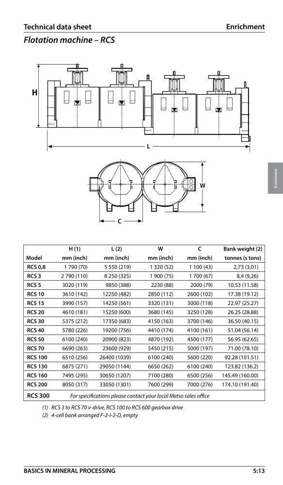
5:13
Enrichment
Enri
chm
ent
BASICS IN MINERAL PROCESSING
�
�
�
H (1) L (2) W C Bank weight (2)
Model mm (inch) mm (inch) mm (inch) mm (inch) tonnes (s tons)
RCS 0,8 1 790 (70) 5 550 (219) 1 320 (52) 1 100 (43) 2,73 (3,01)
RCS 3 2 790 (110) 8 250 (325) 1 900 (75) 1 700 (67) 8,4 (9,26)
RCS 5 3020 (119) 9850 (388) 2230 (88) 2000 (79) 10.53 (11.58)
RCS 10 3610 (142) 12250 (482) 2850 (112) 2600 (102) 17.38 (19.12)
RCS 15 3990 (157) 14250 (561) 3320 (131) 3000 (118) 22.97 (25.27)
RCS 20 4610 (181) 15250 (600) 3680 (145) 3250 (128) 26.25 (28.88)
RCS 30 5375 (212) 17350 (683) 4150 (163) 3700 (146) 36.50 (40.15)
RCS 40 5780 (226) 19200 (756) 4410 (174) 4100 (161) 51.04 (56.14)
RCS 50 6100 (240) 20900 (823) 4870 (192) 4500 (177) 56.95 (62.65)
RCS 70 6690 (263) 23600 (929) 5450 (215) 5000 (197) 71.00 (78.10)
RCS 100 6510 (256) 26400 (1039) 6100 (240) 5600 (220) 92.28 (101.51)
RCS 130 6875 (271) 29050 (1144) 6650 (262) 6100 (240) 123.82 (136.2)
RCS 160 7495 (295) 30650 (1207) 7100 (280) 6500 (256) 145.49 (160.00)
RCS 200 8050 (317) 33050 (1301) 7600 (299) 7000 (276) 174.10 (191.40)
RCS 300 For specifications please contact your local Metso sales office
(1) RCS 3 to RCS 70 v-drive, RCS 100 to RCS 600 gearbox drive (2) 4-cell bank arranged F-2-I-2-D, empty
Flotation machine – RCSTechnical data sheet
W
L
C
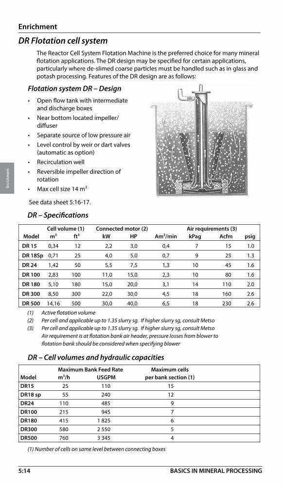
5:14
Enrichment
Enri
chm
ent
BASICS IN MINERAL PROCESSING
DR Flotation cell systemThe Reactor Cell System Flotation Machine is the preferred choice for many mineral flotation applications. The DR design may be specified for certain applications, particularly where de-slimed coarse particles must be handled such as in glass and potash processing. Features of the DR design are as follows:
Flotation system DR – Design• Open flow tank with intermediate
and discharge boxes• Near bottom located impeller/
diffuser• Separate source of low pressure air• Level control by weir or dart valves
(automatic as option)• Recirculation well• Reversible impeller direction of
rotation• Max cell size 14 m3
(1) Active flotation volume (2) Per cell and applicable up to 1.35 slurry sg. If higher slurry sg, consult Metso (3) Per cell and applicable up to 1.35 slurry sg. If higher slurry sg, consult Metso Air requirement is at flotation bank air header, pressure losses from blower to flotation bank should be considered when specifying blower
See data sheet 5:16-17.
DR – Specifications
(1) Number of cells on same level between connecting boxes
DR – Cell volumes and hydraulic capacities Maximum Bank Feed Rate Maximum cells Model m3/h USGPM per bank section (1) DR15 25 110 15DR18 sp 55 240 12DR24 110 485 9DR100 215 945 7DR180 415 1 825 6DR300 580 2 550 5DR500 760 3 345 4
Cell volume (1) Connected motor (2) Air requirements (3) Model m3 ft3 kW HP Am3/min kPag Acfm psig
DR 15 0,34 12 2,2 3,0 0,4 7 15 1.0
DR 18Sp 0,71 25 4,0 5,0 0,7 9 25 1.3
DR 24 1,42 50 5,5 7,5 1,3 10 45 1.6
DR 100 2,83 100 11,0 15,0 2,3 10 80 1.6
DR 180 5,10 180 15,0 20,0 3,1 14 110 2.0
DR 300 8,50 300 22,0 30,0 4,5 18 160 2.6
DR 500 14,16 500 30,0 40,0 6,5 18 230 2.6
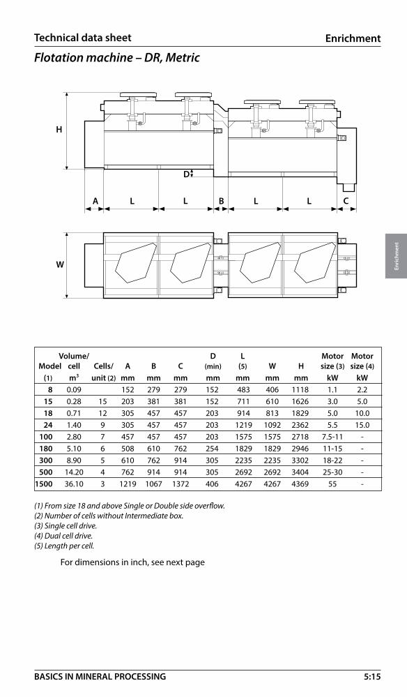
5:15
Enrichment
Enri
chm
ent
BASICS IN MINERAL PROCESSING
Flotation machine – DR, Metric
Technical data sheet
Volume/ D L Motor Motor Model cell Cells/ A B C (min) (5) W H size (3) size (4) (1) m3 unit (2) mm mm mm mm mm mm mm kW kW 8 0.09 152 279 279 152 483 406 1118 1.1 2.2 15 0.28 15 203 381 381 152 711 610 1626 3.0 5.0 18 0.71 12 305 457 457 203 914 813 1829 5.0 10.0 24 1.40 9 305 457 457 203 1219 1092 2362 5.5 15.0 100 2.80 7 457 457 457 203 1575 1575 2718 7.5-11 - 180 5.10 6 508 610 762 254 1829 1829 2946 11-15 - 300 8.90 5 610 762 914 305 2235 2235 3302 18-22 - 500 14.20 4 762 914 914 305 2692 2692 3404 25-30 - 1500 36.10 3 1219 1067 1372 406 4267 4267 4369 55 -
(1) From size 18 and above Single or Double side overflow. (2) Number of cells without Intermediate box. (3) Single cell drive. (4) Dual cell drive. (5) Length per cell.
For dimensions in inch, see next page
W
L
H
A B L C
D
L
W
H
LA B CL L
D

5:16
Enrichment
Enri
chm
ent
BASICS IN MINERAL PROCESSING
Flotation machine – DR, US
Volume/ D L Motor Motor Model cell Cells/ A B C (min) (5) W H size (3) size (4) (1) ft3 unit (2) inch inch incn inch inch inch inch hp hp
8 3 6 11 11 6 19 16 44 1 ½ 3 15 12 15 8 15 15 6 28 24 64 4 7 18 25 12 12 18 18 8 36 32 72 6½ 14 24 50 9 12 18 18 8 48 43 93 7 20 100 100 7 18 18 18 8 62 62 107 10-15 - 180 180 6 20 24 30 10 72 72 116 15-20 - 300 300 5 24 30 36 12 88 88 130 25-30 - 500 500 4 30 36 36 12 106 106 134 30-40 - 1500 1500 3 48 42 54 16 168 168 172 74 -
(1) From size 18 and above Single or Double side overflow. (2) Number of cells without Intermediate box. (3) Single cell drive. (4) Dual cell drive. (5) Length per cell.
For metric dimensions see previous page
Technical data sheet
W
L
H
A B L C
D
L
W
H
LA B CL L
D

5:17
Enrichment
Enri
chm
ent
BASICS IN MINERAL PROCESSING
Column flotation cellsColumn flotation cells, like mechanical cells, are used to perform mineral separations. Column cells do not use mechanical agitation (impellers). Instead, mixing is achieved by the turbulence provided by the rising bubbles. Columns are mostly used to produce final grade concentrates because they are capable of high selectivity. Other features which distinguish them from mechanical cells are their shape, bubble generation system and the use of wash water. An optimum flotation circuit is a combination of mechanical cells and column cells.
In specific applications such as cleaning duties or handling of very fine particles column flotation will offer the following advantages:
• Improved metallurgical performance
• Low energy consumption
• Less floor area
• Less maintenance
• Improved control
Schematic of Microcel flotation column
Wash water
Froth
Non-Floated MICROCEL SPARGER SYSTEM
Air
Slurry feed
Colle
ctio
n zo
neCl
eani
ng z
one
Slurry
Pulp
Automatic control valveor
variable speed pump Air
Valve
Wash waterdistributor
Froth
Static mixer
Recycleslurry pump
Shear element

5:18
Enrichment
Enri
chm
ent
BASICS IN MINERAL PROCESSING
Column flotation – Microcel sparger featuresThe Microcel sparger consists of inline static mixers and a recycle slurry pump. Tailings
slurry is pumped from the base of the column through the static mixers where air and slurry are mixed together under high shear conditions to create the bubble dispersion. As the air/slurry mixture passes through the stationary blades located inside the mixer the air is sheared into very small bubbles by the intense agitation. The bubble suspension is
ApplicationsApplications for flotation columns include:
• Sulfides
• Iron ore
• Phosphate
• Coal
• Industrial minerals
• Potash
introduced near the column base.Slurry level control is achieved by using ultrasonic sensor or differential pressure transmitters to automatically adjust the tailings flow control valve.Wash water addition improves grade by removing mechanically entrained particles.
Standard column optionsColumn size Height Sparger pipe size Air only spargerdiameter m in Sparger quantity port quantity 1,0 m 9, 10, 11, 12, 13 3, 4 1 1 1,5 m 9, 10, 11, 12, 13 4 1,2 3 3,0 m 9, 10, 11, 12, 13 4 6, 7, 8 12 3,6 m 9, 10, 11, 12, 13 4 8, 10 16 4,5 m 10, 11, 12, 13 4 12, 14 24 5,0 m 10, 11, 12, 13, 14 6 6, 7, 8 30
SelectionFor detailed column design – contact your support center supplier. A preliminary indication of design parameters can be derived from the following notes.
• Column designs available up to 6 m in diameter. Flotation column cells are custom designed for each application.
• Typical superficial slurry velocity: 0.2 – 1.2 cm/s
• Typical froth carrying capacity: 2 t/h/m2
• Typical superficial air velocity: 1.5 – 1.8 cm/s
• Height of column selected to give slurry retention time in range 10 – 20 min.
• Typical superficial wash water velocity: 0.05 – 0.2 cm/s

5:19
Enrichment
Enri
chm
ent
BASICS IN MINERAL PROCESSING
Magnetic separation – IntroductionBy creating an environment comprising a magnetic force (Fm), a gravitational force (Fg) and a drag force (Fd) magnetic particles can be separated from non-magnetic particles by Magnetic Separation.
Magnetic separation - Magnetic attraction force (Fm) Fm = V x c x H x grad H V = particle volume (determined by process) c = magnetic susceptibility (see table below) H = magnetic field (created by the magnet system design) in mT (milliTesla) or kG (kiloGauss) 1 kG = 100 mT = 0.1 T grad H = Magnetic field gradient (created by the magnet system design) in mT/m
Magnetic field and magnetic gradient are equally important factors for creating the magnet attraction force.
Mineral Magnetic susceptibility (Xm x 106 emu/g)
Magnetite 20 000 – 80 000 Ferromagnetic (strong magnetic)Pyrrhotite 1 500 – 6 100Hematite 172 – 290 Paramagnetic (weakly magnetic)Ilmenite 113 – 271
Siderite 56 – 64
Chromite 53 – 125
Biotite 23 – 80
Goethite 21 – 25
Monazite 18.9
Malachite 8.5 – 15.0
Bornite 8.0 – 14.0
Rutile 2.0
Pyrite 0.21
Cassiterite – 0.08 Diamagnetic (repelling)Fluorite – 0.285
Galena – 0.35
Calcite – 0.377
Quartz – 0.46
Gypsum – 1.0
Sphalerite – 1.2
Apatite – 2.64
Fd
Fg Fd
Fg
Fm

5:20
Enrichment
Enri
chm
ent
BASICS IN MINERAL PROCESSING
Magnetic separation – Competing forces• Gravitational force (Fg) is determined by particle size and density.
• Drag force (hydrodynamic, aerodynamic), Fd, is determined by particle size, shape, fluid density, viscosity, turbidity and velocity.
• Centripetal force (Fc).
• Adhesion
• Electrostatic forces etc.
Magnetic separation – Methods
Low Intensity Magnetic Separation, LIMS • Dry and wet methods
• For separation of ferromagnetic particles
• Magnetic field intensity up to 300 mT
• Particle sizes up to 300 mm
Medium Intensity Magnetic Separation, MIMS*• Dry and wet methods
• For separation of ferromagnetic particles
• Magnetic field intensity up to 800 mT
*N B At present MIMS is not available from Metso. When MIMS becomes available the above data may alter.
High Gradient Magnetic Separation, HGMS• Cyclic and continuous methods
• For separation of paramagnetic particles
• Magnetic field intensity up to 2 T
• Limited to processing of particles finer than about 1 mm

5:21
Enrichment
Enri
chm
ent
BASICS IN MINERAL PROCESSING
NS
NS
FcFm
Fg
Dry LIMS = Low intensity magnetic separators• Dry separation of ferromagnetic particles
• Magnetic field in* separation zone up to 1.2 kGauss
* approx. 15 mm (5/8 inch) from magnet surface
� �
���������
���
����
����
��
FdFd
Fd
Wet HGMS = High gradient magnetic separators• Wet separation of paramagnetic particles
• Magnetic field in separation zone* = 2 – 20 kGauss
* on matrix surface
Magnetic separation equipmentAll LIMS models, wet and dry versions, comprise magnetic drum assemblies mounted in either tanks or dust housings. The magnetic assembly comprises a stationary magnetic array installed in a rotating outer drum. The drum rotation speed and direction are selected for the application in question.
Generally coarse material is processed by dry LIMS and fine material by either dry or wet LIMS. The upper particle size limit for wet processing is about 8 mm but with special arrangements coarser material can be processed by wet methods.
Magnetic separation – Separator types
Wet LIMS = Low intensity magnetic separators• Wet separation of ferromagnetic particles
• Magnetic field in separation zone * up to 1.2 kGauss
* approx. 50 mm (2 inches) from drum surface
NS N
S
FdFmFg

5:22
Enrichment
Enri
chm
ent
BASICS IN MINERAL PROCESSING
Dry LIMS – Belt drum separator, BSThe belt drum separator, BS, is generally used in iron ore beneficiation to either produce coarse final products or for reducing feed mass to following process stages. It is also used for steel slag and pyrite cinder treatment.
Features
• Magnetic system with three different pole pitches with alternating polarity (models BSA)
• Special pole design with fixed polarity in rotating direction for coarse material, (model BSS)
• For low to high Fe grade feed
• Belt speeds up to 3 m/s (20 ft/min)
• Belt feed for even distribution of feed material
• Adjustable product splitter for product quality control
• Coarse particle tolerant, up to 250 - 300 mm
• Basically used in primary stages
• Can be arranged in single stage or multistage processing
• Very large unit capacity
Recommended pole pitch and capacity ranges
Pole pitch Feed size Feed size Capacity Model (pp) mm inch t/h / m, st/h/ft, up to
BSA1200-112 112 5 – 75 3/16 – 3 150, 50
BSA1200-174 174 5 – 100 3/16 – 4 200, 70
BSA1200-258 258 5 – 200 3/16 – 8 200, 70
BSS1200-300 300 5 – 300 3/16 – 12 400, 140
Capacities vary with grade as well as particle size

5:23
Enrichment
Enri
chm
ent
BASICS IN MINERAL PROCESSING
Dry LIMS – Belt separator (BSA and BSS)
Technical data sheet
Drum W Power Weight Model DxL mm (ft) mm (inch) kW/hp* ton
BSA1206 1200 x 600 (4x2) 1800 (71) 5,5/7,5 2,1
BSA1212 1200x1200 (4x4) 2400 (95) 7,5/10 3,8
BSA1218 1200x1800 (4x6) 3000 (118) 7,5/10 5,6
BSA1224 1200x2400 (4x8) 3600 (142) 7,5/10 7,5
BSA1230 1200x2400 (4x10) 4200 (172) 11/15 9,3
BSS1212 1200x1200 (4x4) 2400 (95) 7,5/10 4,7
BSS1218 1200x1800 (4x6) 3000 (118) 7,5/10 6,9
BSS1224 1200x2400 (4x8) 3600 (142) 7,5/10 9,2
*) At peripheral drum speed 2 m/s (400 ft/min)
H
W
L 4 360 (172)
2 000 (79)
W

5:24
Enrichment
Enri
chm
ent
BASICS IN MINERAL PROCESSING
Dry LIMS – Drum separator, DSThe Dry Drum Separator, DS, is generally used in iron ore beneficiation to either produce coarse final products or for reducing feed mass to following process stages. It is also used for steel slag and pyrite cinder treatment. The metal powder industry uses the separator for final product control.
Features• Magnetic system with four different pole pitches
• For low to high Fe grade feed
• Drum speeds up to 8 m/s (1600 ft/min)
• Top feed
• Coarse particle tolerant, normally up to 20 – 25 mm (3/4 – 1 inch)
• Basically used in primary stages as cobber and rougher
• Can be arranged in single stage or multistage processing
• Can be connected to dust control systems
• Large unit capacity
Recommended pole pitch
Pole pitch Feed size Feed size (pp) mm inch
(25) 45 0 – 5 0 – 3/16
45 0 – 10 0 – 3/8
65 0 – 15 0 – 9/16
112 0 – 20 0 – 3/4
174 0 – 25 0 – 1
Note pp 25 is intended only for special application
DS – Capacities
Type Capacity Capacity t/h and m drum width st/h /ft drum width
DS900 series 50 – 150 15 – 45
DS1200 series 50 – 200 15 – 60
Capacities vary with grade and particle size

5:25
Enrichment
Enri
chm
ent
BASICS IN MINERAL PROCESSING
Dry LIMS – Drum separator – (DS)
Drum dimensions L Power Weight emptyModel DxL mm (ft.) mm (ft.) kW/HP* Ton
DS906 916 x 600 (3x2) 1550 (61) 4/5 1,6
DS912 916 x1200 (3x4) 2170 (85) 5,5/7,5 2,5
DS918 916 x1800 (3x6) 2780 (109) 7,5/10 3,2
DS924 916 x2400 (3x8) 3400 (134) 7,5/10 4,0
Drum dimensions L Power Weight emptyModel DxL mm (ft.) mm (ft.) kW/HP* Ton
DS1206 1200 x 600 (4x2) 1550 (61) 4/5 2,2
DS1212 1200 x1200 (4x4) 2170 (85) 5,5/7,5 3,1
DS1218 1200 x1800 (4x6) 2780 (109) 7,5/10 3,9
DS1224 1200 x2400 (4x8) 3400 (134) 7,5/10 4,8
DS1230 1200 x3000 (4x10) 4020 (158) 7,5/10 5,6
*) At drum peripheral speed of 2 m/s (400 ft/min)
Technical data sheet
H
L AB WH WL
H 1400 (55)
1360 (54)
H
L AB WH WL
H 1670 (66)
1844 (73)

5:26
Enrichment
Enri
chm
ent
BASICS IN MINERAL PROCESSING
Wet LIMS – Concurrent CC• Medium lenght magnetics pick up zone• Standard magnetic system• For low to high Fe grade feed• Concurrent operation• Tank bottom spigots for tailings flow control• Coarse particle tolerant, normally up to 8 mm• Used in primary stages as cobber and rougher• Can be arranged as single stage or multistage units on same level for
reprocessing of the magnetic product• Large unit capacity• Feed density acceptable in a wide range, normally 35 to 45 percent solids by
weight
Please always check with Metso for final selection!
Wet LIMS – Wet magnetic separatorsThe wet magnetic separators are generally used in the iron ore industry in several stages of the process from coarse separation to fine concentration of magnetite ore, in single concentration means or in combination with other methods (e.g. flotation, gravity concentration, screening).
Wet LIMS are also used in other mineral industries for e.g. preparation of dense media, reduction of pyrrhotite content in base metal concentrates, removal of ferromagnetic contaminants etc.

5:27
Enrichment
Enri
chm
ent
BASICS IN MINERAL PROCESSING
Wet LIMS – Countercurrent CTC and CTCHG• Long magnetics pick up zone• Available with either standard or High Gradient magnetic systems• Countercurrent operation • Commonly arranged as multistage units on same level for reprocessing of the
magnetic product• Fixed overflow weir for tailings flow control• Medium particle tolerant, normally up to 0,8 mm• Used in cleaning or finishing stages • Feed density acceptable in a wide range, normally up to 40 percent solids by weight
Wet LIMS – Counter rotation CR and CRHG• Extra long magnetics pick up zone • Available with either standard or High Gradient magnetic systems• For low to high Fe grade feed• Counter rotational operation• Manually adjustable weir for tailings flow control• Coarse particle tolerant, normally up to 3-4 mm• Used in primary stages as cobber or rougher• Also used for dense media recovery• Large unit capacity• Mostly used in single unit operation but can installed as double units on two
levels • Feed density acceptable in a wide range, normally 25 to 45 percent solids by
weight

5:28
Enrichment
Enri
chm
ent
BASICS IN MINERAL PROCESSING
Wet LIMS – Counter rotation froth DWHG• Long magnetics pick up zone• High Gradient magnetic systems• Counter rotational operation • Extra large feed box for deaeration of feed slurry• Normally installed as a single stage unit• Manually adjustable weir for tailings flow control• Coarse particle tolerant, normally up to 3-4 mm• Designed to improve recovery from aerated (frothy) slurries• Used for recovery of magnetics in slurries emanating from flotation • Feed density acceptable in a wide range, normally up to 45 percent solids by weight
InletSlurry
Separator drum
OutletTailings
OutletMagnetic Concentrate
Separator tank
Wet LIMS – Dense media recovery DM and DMHG• Very long magnetics pick up zone
• Standard and High Gradient (HG) magnetic systems available
• For low to high Fe grade feed
• Concurrent operation with long magnetics pick-up zone
• Bottom spigots combined with effluent weir overflow for tailings flow control
• Coarse particle tolerant, normally up to 8 mm
• Used in both primary and secondary stages in single stage units
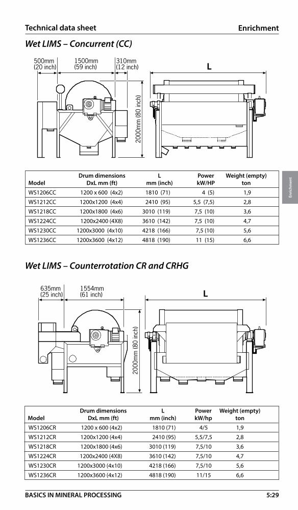
5:29
Enrichment
Enri
chm
ent
BASICS IN MINERAL PROCESSING
Technical data sheet
Wet LIMS – Concurrent (CC)
Drum dimensions L Power Weight (empty)Model DxL mm (ft) mm (inch) kW/HP ton
WS1206CC 1200 x 600 (4x2) 1810 (71) 4 (5) 1,9
WS1212CC 1200x1200 (4x4) 2410 (95) 5,5 (7,5) 2,8
WS1218CC 1200x1800 (4x6) 3010 (119) 7,5 (10) 3,6
WS1224CC 1200x2400 (4X8) 3610 (142) 7,5 (10) 4,7
WS1230CC 1200x3000 (4x10) 4218 (166) 7,5 (10) 5,6
WS1236CC 1200x3600 (4x12) 4818 (190) 11 (15) 6,6
��������������
���������������
��������������
����
�����
������
�
�
Wet LIMS – Counterrotation CR and CRHG
Drum dimensions L Power Weight (empty)Model DxL mm (ft) mm (inch) kW/hp ton
WS1206CR 1200 x 600 (4x2) 1810 (71) 4/5 1,9
WS1212CR 1200x1200 (4x4) 2410 (95) 5,5/7,5 2,8
WS1218CR 1200x1800 (4x6) 3010 (119) 7,5/10 3,6
WS1224CR 1200x2400 (4X8) 3610 (142) 7,5/10 4,7
WS1230CR 1200x3000 (4x10) 4218 (166) 7,5/10 5,6
WS1236CR 1200x3600 (4x12) 4818 (190) 11/15 6,6
��������������
���������������
����
�����
������
�
�

5:30
Enrichment
Enri
chm
ent
BASICS IN MINERAL PROCESSING
Wet LIMS – Countercurrent CTC and CTCHG
��������������
���������������
�������������� �
����
�����
������
�
Drum dimensions L Power Weight (empty)Model DxL mm (ft) mm (inch) kW/hp ton
WS1206CTC 1200 x 600 (4x2) 1810 (71) 4/5 1,9
WS1212CTC 1200x1200 (4x4) 2410 (95) 5,5/7,5 2,8
WS1218CTC 1200x1800 (4x6) 3010 (119) 7,5/10 3,6
WS1224CTC 1200x2400 (4X8) 3610 (142) 7,5/10 4,7
WS1230CTC 1200x3000 (4x10) 4218 (166) 7,5/10 5,6
WS1236CTC 1200x3600 (4x12) 4818 (190) 11/15 6,6
WS1200CTC and WS1200CTCHG carry identical dimensions
Technical data sheet
Drum dimensions L Power Weight (empty)Model DxL mm (ft) mm (inch) kW/hp ton
WS1206DWHG 1200 x 600 (4x2) 1810 (71) 1,5/2,0 1,9
WS1212DWGH 1200x1200 (4x4) 2410 (95) 2,2/3,0 2,8
WS1218DWHG 1200x1800 (4x6) 3010 (119) 3,0/4,0 3,6
WS1224DWHG 1200x2400 (4X8) 3610 (142) 3,0/4,0 4,7
WS1230DWHG 1200x3000 (4x10) 4218 (166) 4,0/5,0 5,6
WS1236DWHG 1200x3600 (4x12) 4818 (190) 4,0/5,0 6,6
1020 mm40 inch
2575 mm, 101 inch
Wet LIMS – Counter rotation froth DWHG��������������
���������������
����
�����
������
�
�

5:31
Enrichment
Enri
chm
ent
BASICS IN MINERAL PROCESSING
Technical data sheet
Wet LIMS – Dense media DM and DMHG
���������������
��������������
����
�����
������
�
�
Drum dimensions L Power Weight (empty)Model D x L mm (ft) mm (inch) kW/hp ton
WS1206DM 1200 x 600 (4x2) 1810 (71) 1,5/2,0 1,9
WS1212DM 1200x1200 (4x4) 2410 (95) 2,2/3,0 2,8
WS1218DM 1200x1800 (4x6) 3010 (119) 3,0/4,0 3,6
WS1224DM 1200x2400 (4X8) 3610 (142) 3,0/4,0 4,7
WS1230DM 1200x3000 (4x10) 4218 (166) 4,0/5,0 5,6
WS1236DM 1200x3600 (4x12) 4818 (190) 4,0/5,0 6,6
WS1200DM and WS1200DMHG carry identical physical dimensions
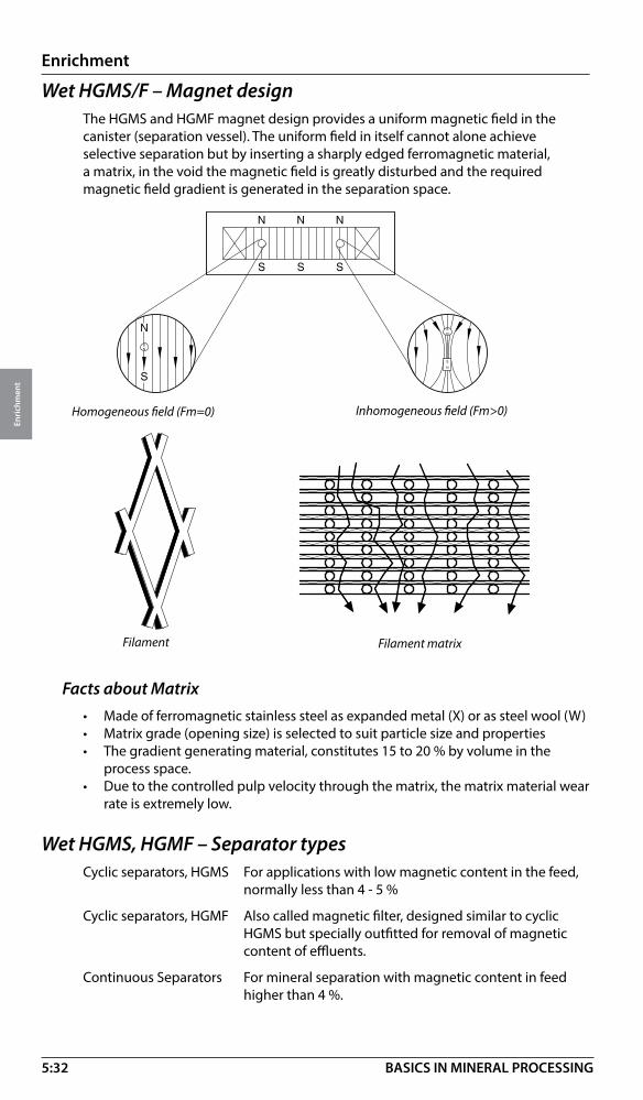
5:32
Enrichment
Enri
chm
ent
BASICS IN MINERAL PROCESSING
Wet HGMS/F – Magnet designThe HGMS and HGMF magnet design provides a uniform magnetic field in the canister (separation vessel). The uniform field in itself cannot alone achieve selective separation but by inserting a sharply edged ferromagnetic material, a matrix, in the void the magnetic field is greatly disturbed and the required magnetic field gradient is generated in the separation space.
Homogeneous field (Fm=0) Inhomogeneous field (Fm>0)
Filament Filament matrix
Facts about Matrix• Made of ferromagnetic stainless steel as expanded metal (X) or as steel wool (W)• Matrix grade (opening size) is selected to suit particle size and properties• The gradient generating material, constitutes 15 to 20 % by volume in the
process space. • Due to the controlled pulp velocity through the matrix, the matrix material wear
rate is extremely low.
Wet HGMS, HGMF – Separator typesCyclic separators, HGMS For applications with low magnetic content in the feed, normally less than 4 - 5 %
Cyclic separators, HGMF Also called magnetic filter, designed similar to cyclic HGMS but specially outfitted for removal of magnetic content of effluents.
Continuous Separators For mineral separation with magnetic content in feed higher than 4 %.
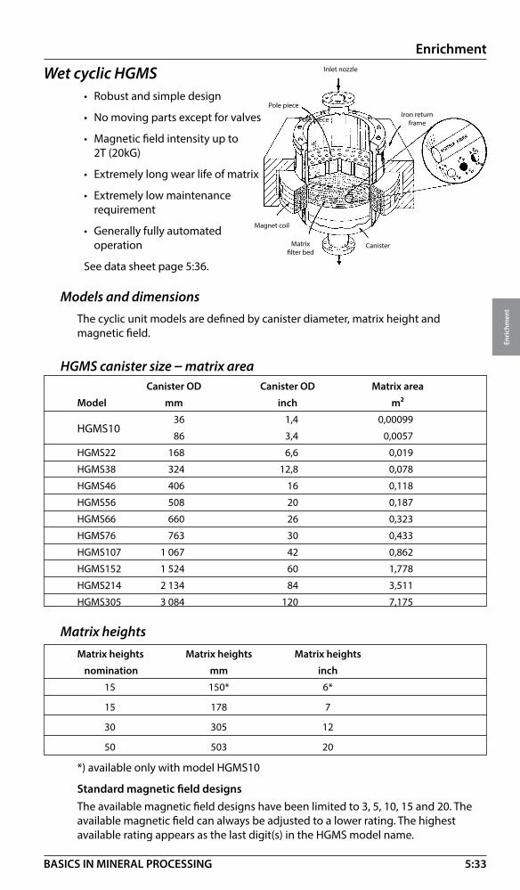
5:33
Enrichment
Enri
chm
ent
BASICS IN MINERAL PROCESSING
Inlet nozzle
Pole pieceIron return
frame
CanisterMatrix filter bed
Magnet coil
Pole piece
Wet cyclic HGMS• Robust and simple design
• No moving parts except for valves
• Magnetic field intensity up to 2T (20kG)
• Extremely long wear life of matrix
• Extremely low maintenance requirement
• Generally fully automated operation
See data sheet page 5:36.
Models and dimensionsThe cyclic unit models are defined by canister diameter, matrix height and magnetic field.
HGMS canister size – matrix area Canister OD Canister OD Matrix area
Model mm inch m²
HGMS10 36 1,4 0,00099
86 3,4 0,0057
HGMS22 168 6,6 0,019
HGMS38 324 12,8 0,078
HGMS46 406 16 0,118
HGMS56 508 20 0,187
HGMS66 660 26 0,323
HGMS76 763 30 0,433
HGMS107 1 067 42 0,862
HGMS152 1 524 60 1,778
HGMS214 2 134 84 3,511
HGMS305 3 084 120 7,175
Matrix heights Matrix heights Matrix heights Matrix heights
nomination mm inch
15 150* 6*
15 178 7
30 305 12
50 503 20
*) available only with model HGMS10
Standard magnetic field designsThe available magnetic field designs have been limited to 3, 5, 10, 15 and 20. The available magnetic field can always be adjusted to a lower rating. The highest available rating appears as the last digit(s) in the HGMS model name.

5:34
Enrichment
Enri
chm
ent
BASICS IN MINERAL PROCESSING
Model definitionIn the model name canister diameter, matrix height and nominal magnetic rating are appearing, e.g. HGMS107-15-10 had a diameter of 1067mm a matrix height of 178 mm and a magnetic rating of 10 kG.
Matrix grades for cyclic HGMS unitsMatrix Type of Maximum particle Maximum particle grade matrix size, µm size, mesh
XR1.1 Expanded metal 1000 16
XR Expanded metal 800 22
XM1.1 Expanded metal 450 35
XM Expanded metal 350 42
XMG0 Expanded metal 300 48
XF1.1 Expanded metal 150 106
XF Expanded metal 100 150
WC Steel wool 20
WM Steel wool 10
WF Steel wool 7
CONTROLLER
POWERSUPPL Y
FLUSH W ATER
RINSE WATER
MAGNET
FEED
NON-MAGNETICPRODUCT
MA TRIX
MAGNETICPRODUCT
to valves
s
s
RETURN FRAME
COIL
FEED
to valvesCONTROLLER
POWERSUPPLY
RINSEWATER
MAGNET
RETURN FRAME
COIL
FLUSH WATER
NON-MAGNETICPRODUCT
MATRIX
Wet cyclic HGMS – Process system• Compact system design
• Fail-safe protection (thermal)
• Customer built power supply
• Completely automatic process control
Wet cyclic HGMS – Operation
Magneton
Feed
Non-mag.product
Magneton
Non-mag.product
Rinsewater
Magnetoff
Magnetoff
Mag.product
Flushwater
FEED
RINSEWATER
MAGNETON
FLUSH WATER
NON-MAGNETICPRODUCT
NON-MAGNETICPRODUCT
MAGNETON
MAGNETOFF
MAGNETOFF
MAGNETICPRODUCT
Cycle 1 Cycle 2 Cycle 3 Cycle 4 Separation Rinse Demagnetizing Flushing
• Magnet activated • Magnet activated • Magnet off • Magnet off• Feed on • Feed off • Feed off • Feed off • Washing on • Washing off • Washing on

5:35
Enrichment
Enri
chm
ent
BASICS IN MINERAL PROCESSING
Typical cycle times (Kaolin separation): Separation 4 min.
Rinse 1.5 min.
Magnetizing / Demagnetizing < 1 min.
Flush < 1 min.
Wet cyclic HGMS – Applications• Kaolin beneficiation (brightening)
• Fe2O3 reduction in glass sand, feldspar, barite
• Cu-reduction in Mo Cu concentrates
• De-ashing and desulphurisation of coal
• Phosphates upgrading
• Testing and research (Laboratory unit HGMS10-15-20)
Wet cyclic HGMS – Sizing (indicative)Ex: Cleaning of kaolin clay, 4 t/h. Select the separator size.
1. Calculate the cycle time:
• Feed 4 min.
• Rinse 1.5 min.
• Magnet on/off 1 min.
• Flushing 1 min.
Total cycle time 7.5 min.
2. Calculate the actual separation time (feed) from 1. above
4 / (4 + 1,5 + 1 + 1) = 4 / 7,5 = 0,53 (53%)
3. Calculate the volume flow of 4.0 t/h (at say 25% solids and S.G. 2.5) which gives 13.6 m3/h (0.75 ft / min)
As actual separation time is 53% of total time, separator volumetric capacity must be = 13,6/0,53 = 25,7 m³/h (15.1 cuft / min)
4. Kaolin (very fine particles) means matrix of W-type. Typical flow velocity for kaolin processing is 8 mm/s or 28,8 m/h (19.0 inch / min)
5. Calculate separator size matrix area (m²) = volume capacity (m³/h) / flow velocity (m/h) = 25,7 / 28,8 = 0,89 m² (9.6 sqft)
Machine size, see above, is HGMS 107-30-20

5:36
Enrichment
Enri
chm
ent
BASICS IN MINERAL PROCESSING
Wet cyclic HGMS
Technical data sheet
H
W
L
Power Weight H L W (magnet) (empty) Matrix areaModel mm (ft) mm (ft) mm (ft) kW ton m² (ft²)
38-15-10* 4 000 (13) 3 800 (12) 2 450 (8) 40 10 0.11 (1.18)
56-15-10 4 100 (13) 4 000 (13) 2 450 (8) 46 13 0.19 (2.05)
76-15-10 4 100 (13) 4 200 (14) 2 450 (8) 53 14 0.43 (4.63)
107-15-10 4 380 (14) 5 150 (17) 2 900 (10) 63 26 0.85 (9.15)
152-15-10 ** ** ** 80 46 1.75 (18.84)
214-15-10 ** ** ** 103 ** 3.42 (36.81)
305-15-10 ** ** ** - ** 7.30 (78.58)
*38-15-10= 38(Outer diameter in cm)-15 (matrix height in cm) -10 (field rating in kGauss)
Magnetic field available 5,10,15 and 20 kGauss
** Site specific
W
L
H

5:37
Enrichment
Enri
chm
ent
BASICS IN MINERAL PROCESSING
Wet cyclic high gradient magnetic filter HGMFThe Cyclic HGMF is in principle based on the cyclic HGMS but arranged to work as filter instead of as separator. It is normally used for magnetic filtration of liquids and effluents.
Features • Robust and simple design• No moving parts except for valves• Magnetic field intensity up to 2T (20kG)• Extremely long wear life of matrix• Extremely low maintenance requirement• Generally fully automated operation• Can be arranged for special process requirements like high pressure and
temperatures See data sheet page 5:41.
Models and sizesThe cyclic HGMF units are defined by canister diameter, matrix height and magnetic field.
The laboratory model is available as HGMS10-15-20 and is used for both HGMS and HGMF investigations.

5:38
Enrichment
Enri
chm
ent
BASICS IN MINERAL PROCESSING
Standard magnetic field designsThe available magnetic field designs have been limited to 3, 5, 10, 15 and 20. The available magnetic field can always be adjusted to a lower rating. The highest available rating appears as the last digit(s) in the HGMS model name.
Model definitionIn the model name canister diameter, matrix height and nominal magnetic rating are appearing, e.g. HGMF107-15-10 has a diameter of 1067mm a matrix height of 178 mm and a magnetic rating of 10 kG.
Matrix grades for cyclic HGMF units
Matrix Type of Maximum particle Maximum particle grade matrix size, µm size, mesh
XR1.1 Expanded metal 1000 16XR Expanded metal 800 22XM1.1 Expanded metal 450 35XM Expanded metal 350 42XMG0 Expanded metal 300 48XF1.1 Expanded metal 150 106XF Expanded metal 100 150WC Steel wool 20 WM Steel wool 10 WF Steel wool 7
Canister OD Canister OD Matrix area
Model mm inch m²
HGMS10 36 1,4 0,00099
86 3,4 0,0057HGMF22 168 6,6 0,019HGMF38 324 12,8 0,078HGMF46 406 16,0 0,118HGMF56 508 20,0 0,187HGMF66 660 26,0 0,323HGMF76 763 30,0 0,433HGMF107 1 067 42,0 0,862HGMF152 1 524 60,0 1,778HGMF214 2 134 84,0 3,511HGMF305 3 084 120,0 7,175
Matrix heights Matrix heights Matrix heights Matrix heights
nomination mm inch 15 150* 6*
15 178 7
30 305 12
50 503 20
*) available only with model HGMS10
HGMF – Canister diameters and matrix areas

5:39
Enrichment
Enri
chm
ent
BASICS IN MINERAL PROCESSING
HGMF - ApplicationsGenerally: For high pressure, high temperature and “lack of space” applications
• Removal of iron and copper particles from boiler circuits• Cleaning of district heating systems• Removal of weakly magnetic particles from process water (mill scale,
metal lurgical dust etc.)
HGMF – Process dataSolids in feed Normally low ppm levels
Particle size in feed Restricted by matrix type Matrix type XF will allow particles – 100 microns
HGMF – SizingSizing similar to conventional clarification sizing, see section 6:3.
Surface load (m3/h)/m2 and (ft3/h)/ft2 is the flow velocity through the matrix for optimal clarification.
Surface load Surface load
Application * (m3/h)/m2 (ft3/h)/ft2 Flush interval
Condensate polishing 500 – 1 500 27 – 81 7 – 21 days
District heating systems 500 – 1 500 27 – 81 24 hours
Steel mill cooling water 200 – 800 11 – 44 0.3 – 1 hours
* Magnetic field 3 kg
Ex 1:
Steel mill cooling water can be treated with a surface load of 500 (m3/h)/m2 at 3 kG. The flow is 800 m3/h.
Required area 800 / 500 = 1.6 m2
Select HGMF 152 - 15 - 3
Ex 2:
Paper mill Condensate water can be treated with a surface load of approx. 500 GPMPSF (Gallon per minute per square foot)
Flow is 3000 GPM
HGMF model 107 has an area = 9.1 ft2
3000 / 9.1 = 330 GPMPSF (OK!)

5:40
Enrichment
Enri
chm
ent
BASICS IN MINERAL PROCESSING
Wet cyclic high gradient magnetic filter – HGMFTechnical data sheet
W
L
H
W
L
H
H L W Power (magnet) Matrix areaModel mm (ft) mm (ft) mm (ft) kW m² (ft²)
38-15-3* 1 905 (6) 3 048 (10) 1 321 (4) 9 0.07 (0.8)
45-15-3 2 032 (7) 3 556 (12) 1 524 (5) 12 0.11 (1.2)
56-15-3 2 210 (7) 4 064 (13) 1 829 (6) 12 0.19 (2.0)
76-15-3 2 464 (8) 4 115 (14) 1 829 (6) 24 0.43 (4.6)
107-15-3 3 073 (10) 5 588 (18) 1 981 (7) 24 0.85 (9.15)
152-15-3 ** ** ** 28 1.75 (18.84)
214-15-3 ** ** ** 37 3.42 (36.81)
*38-15-3= 38 (Outer diameter in cm)-15 (matrix height in cm) -3 (field rating in kGauss)
Magnetic field available 3,5,10,15 and 20 kGauss
** Site specific

5:41
Enrichment
Enri
chm
ent
BASICS IN MINERAL PROCESSING
��������������������
�
����
�
�
����������������
����������������
���
Wet continuous HGMSFeatures
• Continuous operation
• Fully automatic processing
• Broad range of applications
• Fine particle processing
• High separation efficiency
• Reliable design
• Low specific power consumption
• Large process capacity
• Long component life See data sheet page 5:44
Wet continuous HGMS – Process system1. Oversize control
2. Passive matrix
3. Separator
4. Power supply
5. Cooling system
6. Vacuum system
7. Control system
Wet continuous HGMS – Applications1. Concentration of paramagnetic oxide minerals such as:
• Chromite • Hematite • Ilmenite • Manganite • Volframite
2. Rare earth minerals3. Industrial minerals (reduction of paramagnetic contaminations)4. Coal (desulphurization and de-ashing)5. Separation of base metal minerals such as:
• Cu-Mo • Cu-Pb • Zn-Pb

5:42
Enrichment
Enri
chm
ent
BASICS IN MINERAL PROCESSING
Matrix Type of Maximum particle Maximum particle grade matrix size, µm size, mesh
XR1.1 Expanded metal 1000 16
XR Expanded metal 800 22
XM1.1 Expanded metal 450 35
XM Expanded metal 350 42
XMG0 Expanded metal 300 48
XF1.1 Expanded metal 150 106
XF Expanded metal 100 150
Wet continuous HGMS – Approximate water consumption Rinse/mag head Flush/mag head Seal water/unit Cooling water* Size (m3/h) (m3/h) (m3/h) (m3/h) 120 15 20 8 3 185 70 90 12 4 250 200 250 27 6 350 350 450 40 9
* One magnet head 7 kGauss
Rinse/mag head Flush/mag head Seal water/unit Cooling water* Size (USGPM) (USGPM) (USGPM) (USGPM) 120 65 90 35 15 185 310 395 50 20 250 880 1 095 120 25 350 1 535 1 975 175 40
* One magnet head 7 kGauss
Magnetic field Matrix loading Flow velocityApplication T g/cm3 mm/sHematite 0,3 – 0,7 0,3 – 0,65 180 – 250Martite 0,3 – 0,7 0,3 – 0,6 180 – 250Ilmenite 0,5 – 0,7 0,3 – 0,45 180 – 200Chromite 0,5 – 0,7 0,3 – 0,5 150 – 200Manganese 1,0 – 1,5 0,3 – 0,5 100 – 200Apatite 0,7 – 1,5 0,3 100 – 150Kyanite 1,5 0,3 100 – 150Wolframite 1,0 0,3 100 – 150Nepheline Syenite 1,2 – 1,5 0,3 60 – 90Glass sand 1,5 0,3 – 1,0 60 – 90Mica 0,8 – 1,0 0,3 – 0,8 60 – 90Retreatment of current tailings and exist. deposits Varying Varying Varying
Matrix grades for continuous HGMS units
Wet continuous HGMS – Sizing and selectionNote: The sizing and selection of the equipment should be carried out by authorized personnel.Matrix loading (ML) = Allowable feed solids (dry weight) per matrix volume, g/cm3. Pulp flow velocity (PFV), mm/s The factors feed density, Magnetic field, ML and PFV are determined by laboratory testing. The data in the tables below are only indicative.
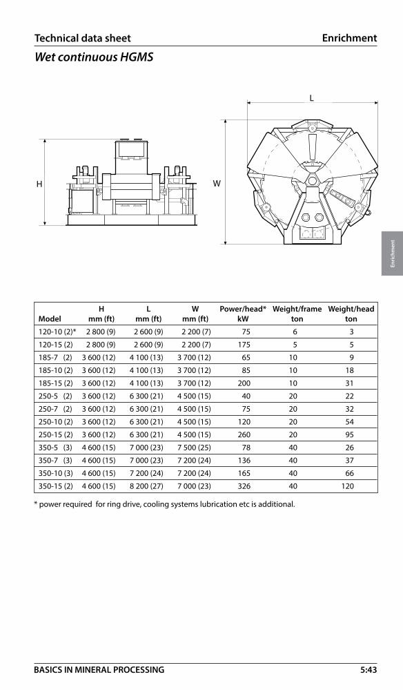
5:43
Enrichment
Enri
chm
ent
BASICS IN MINERAL PROCESSING
Wet continuous HGMSTechnical data sheet
W
L
H W
L
H
H L W Power/head* Weight/frame Weight/headModel mm (ft) mm (ft) mm (ft) kW ton ton
120-10 (2)* 2 800 (9) 2 600 (9) 2 200 (7) 75 6 3
120-15 (2) 2 800 (9) 2 600 (9) 2 200 (7) 175 5 5
185-7 (2) 3 600 (12) 4 100 (13) 3 700 (12) 65 10 9
185-10 (2) 3 600 (12) 4 100 (13) 3 700 (12) 85 10 18
185-15 (2) 3 600 (12) 4 100 (13) 3 700 (12) 200 10 31
250-5 (2) 3 600 (12) 6 300 (21) 4 500 (15) 40 20 22
250-7 (2) 3 600 (12) 6 300 (21) 4 500 (15) 75 20 32
250-10 (2) 3 600 (12) 6 300 (21) 4 500 (15) 120 20 54
250-15 (2) 3 600 (12) 6 300 (21) 4 500 (15) 260 20 95
350-5 (3) 4 600 (15) 7 000 (23) 7 500 (25) 78 40 26
350-7 (3) 4 600 (15) 7 000 (23) 7 200 (24) 136 40 37
350-10 (3) 4 600 (15) 7 200 (24) 7 200 (24) 165 40 66
350-15 (2) 4 600 (15) 8 200 (27) 7 000 (23) 326 40 120
* power required for ring drive, cooling systems lubrication etc is additional.

5:44
Enrichment
Enri
chm
ent
BASICS IN MINERAL PROCESSING
� � � � �
Leaching of metalsBelow find the flow sheets for classical leaching circuits, heap leaching for coarse fractions (crushing only) of low grade ores and agitation leaching for finer fraction of high value ores.
In the heap leaching process the ground is protected by a sealed surface, collecting the leaching chemicals, re- circulated by pumping. When the solution is “pregnant” its clarified by sedimentation or sand filtration and taken to metal recovery by electrowinning.
In the agitation leaching circuit the feed is finer (typical –200 microns) and the slurry moves in the same direction as the chemicals (con current flow). In this case, the pregnant solution has to be recovered from the solids by mechanical dewatering due to particle size, see section 6.
minus 20 mmAcids
Leaching solution
Metal recoveryElectrowinning
Sand filter
minus 0.2 mm
Acids
Trash
Metal recoveryElectrowinning Tailings
Air pressure filter(Solid/liquid separation)

5:45
Enrichment
Enri
chm
ent
BASICS IN MINERAL PROCESSING
Gold leachingEnrichment by leaching is mainly used for recovery of gold often in combination with pre separation by gravity. If free coarse gold is released during size reduction, this fraction (typical – 1mm) is recovered in gravity spirals, see 5:8. If finer fractions of free gold are present centrifuge technology can be applied (not covered here). Alternatively, when processing an ore containing gold metal only, leaching with carbon adsorption are frequently used.
Gold leaching – Carbon adsorptionLeaching reaction
2 Au + 4 CN¯ + O2 (air)+ 2H2 O 2 Au (CN)2¯ + OH¯ pH>8 (lime)
Process stages
1. Leaching by agitation to dissolve Au by reaction above. Agitators are arranged in con current flow. CIL (Carbon in leach) is a method where the gold adsorption by carbon is done in the leaching circuit. The method, seldom used due to high operating costs, is not covered here.
2. CIP (Carbon in pulp) adsorption by slow agitation using active carbon granules to adsorb the Au solution from the pulp. Agitators are arranged in counter current flow (carbon travelling towards the pulp flow). See flowsheet on next page.
Carbon granules must be:
a. Hard to resist abrasion (made from coconut shells)
b. Coarse to be separated from slurry by sizing (1-3 mm, 16-6 Mesh)
c. High in specific surface
3. Carbon recovery is done by sizing over a screen (cut at 0,7 mm, 24 Mesh) bringing the loaded carbon out of the pulp system
4. Au stripping is the process of removing the gold solution by “washing” the carbon granules in a solution (cyanide + Na OH) at 135°C. (retention time 6-8 hours).
5. Carbon reactivation is needed after the washing to restore the active surface of the granules. This is done in a kiln at 125° C
6. Cyanide destruction of the pulp leaving the CIP circuit is done in an agitator adding an oxidant (typical hypocloride) bringing remaining cyanide to a harmless state.
7. Au electrowinning by plating out the gold metal is done with steel wool cathodes. These cathodes are sent to fluxing and smelting (8).
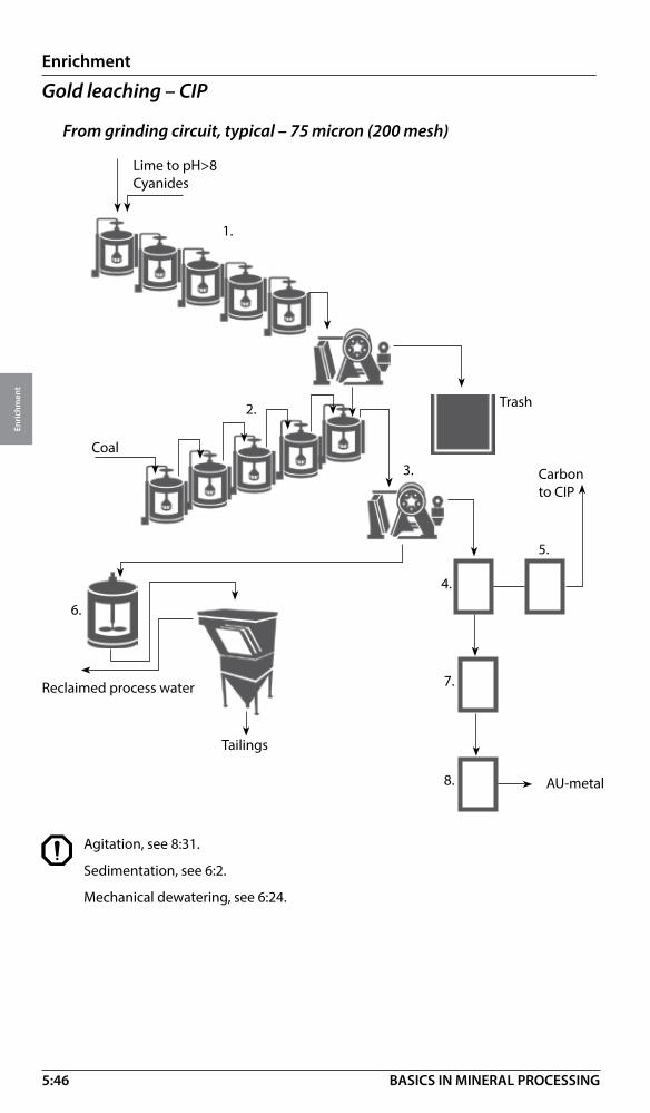
5:46
Enrichment
Enri
chm
ent
BASICS IN MINERAL PROCESSING
Gold leaching – CIP
From grinding circuit, typical – 75 micron (200 mesh)
Agitation, see 8:31.
Sedimentation, see 6:2.
Mechanical dewatering, see 6:24.
1.
2.
3.
4.
5.
6.
7.
8.
Lime to pH>8 Cyanides
Coal
Carbon to CIP
AU-metal
Tailings
Reclaimed process water
Trash
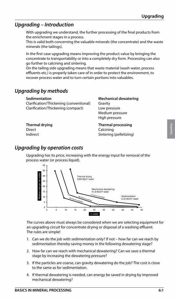
6:1
Upgrading
Upg
radi
ng
BASICS IN MINERAL PROCESSING
Upgrading – IntroductionWith upgrading we understand, the further processing of the final products from the enrichment stages in a process.This is valid both concerning the valuable minerals (the concentrate) and the waste minerals (the tailings).
In the first case upgrading means improving the product value by bringing the concentrate to transportability or into a completely dry form. Processing can also go further to calcining and sintering.On the tailing side upgrading means that waste material (wash water, process effluents etc.) is properly taken care of in order to protect the environment, to recover process water and to turn certain portions into valuables.
Upgrading by methods Sedimentation Mechanical dewatering Clarification/Thickening (conventional) GravityClarification/Thickening (compact) Low pressure Medium pressure High pressure
Thermal drying Thermal processing Direct CalciningIndirect Sintering (pelletizing)
Upgrading by operation costsUpgrading has its price, increasing with the energy input for removal of the process water (or process liquid).
The curves above must always be considered when we are selecting equipment for an upgrading circuit for concentrate drying or disposal of a washing effluent. The rules are simple!
1. Can we do the job with sedimentation only? If not – how far can we reach by sedimentation thereby saving money in the following dewatering stage?
2. How far can we reach with mechanical dewatering? Can we save a thermal stage by increasing the dewatering pressure?
3. If the particles are coarse, can gravity dewatering do the job? The cost is close to the same as for sedimentation.
4. If thermal dewatering is needed, can energy be saved in drying by improved mechanical dewatering?
Thermal drying 2260 Mj/m3 water

6:2
Upgrading
Upg
radi
ng
BASICS IN MINERAL PROCESSING
FlocculationAll sedimentation technologies are related to particle size. One way of improving the settling speed generally is therefore to increase the size of the particles.
Fine particles can be connected together by coagulation or flocculation. The settling rate of the combined particles will be higher than that of each individual particle. This can also be applied prior to mechanical dewatering.
Coagulation: Surface charges are neutralized by addition of chemicals of opposite charge.
Ex: Fe+++ (iron sulphate)Al+++ (aluminium sulphate)Ca++ (lime)
A coagulated aggregate will reform after breaking (e.g. pumping).
Flocculation: Polymers with molecule chains which physically link the particles together (mechanical bridging).
A flocculated aggregate will not reform after breaking.
Flocculation systemA handling system is needed for flocculent utilisation. This comprises provision to mix, store and dilute the polymer. The dilute polymer is then mixed with the feed slurry and allowed to condition (or age) before a sedimentation or dewatering process.
Flocculation - addition and mixing time Mixing time Addition rateApplication Flocculant charge min g/m3
Sand wash water an- or non-ionic 0.5 – 1 0.5 – 5Scrubber water (gas cleaning) an-ionic 0.5 – 2 0.5 – 2Coal tailings non- and cat.ionic 0.5 – 1 2.0 – 10Mineral tailings an-ionic 0.5 – 1 1.0 – 5 (40-80 g/t)
SedimentationSedimentation is a continuous solid-liquid separation process with settling of solids by gravity. Clarification is the process for removal of solids from a dilute solid/liquid suspension. Thickening is the process for concentrating particles in a supension by gravity compression
To sedimentation

6:3
Upgrading
Upg
radi
ng
BASICS IN MINERAL PROCESSING
Conventional clarifierClarification is achieved when the liquid “upstream” velocity VL (rise rate) is lower than the sedimentation velocity of the solids VS
Example
A wash water (100 m3/h) coming from a sand operation needs to be clarified. Surface load is 0.5 m3/h/m2. Select clarifier diameter.
Required area is: 100/0.5 = 200 m2= pd2
= 200 where d is required diameter = 15.9. 4
Select a 16 m clarification tank!
Note! When thickening is also a critical part of the sedimentation process, the tank diameter has to be cross-checked with the diameter for thickener duty, see next page.
Conventional clarifier – sizingClarifier diameter is selected to give a suitable upstream velocity (m/h). Sizing is usally done using “Surface Load”, meaning the volume of slurry m3/h fed per m2 of clarifier surface. Typical surface loads are given below.
Surface load Surface load Surface loadmaterial Feed % m3/m2, h ft3/ft2, minBrine purification 0.1 – 5 0.5 – 1.7 0.03 – 0.07Coal refuse 0.5 – 6 0.7 – 1.7 0.04 – 0.09Clean coal fines 1.0 – 5 1.0 – 1.9 0.06 – 0.10 (with flocculation) Heavy media magnetite 20 – 30 6 – 7.5 0.32 – 0.41Gas cleaning 0.2 – 2 1.5 – 3.7 0.08 – 0.20 (with flocculation) Gypsum desulphurization 1 – 3 1 – 2 0.06 – 0.12Sand wash water 1 – 5 0.3 – 1 0.02 – 0.06 (without flocculation) 1 – 5 1 – 4 0.06 – 0.22 (with flocculation)Ore flotation tailings 10 – 20 0.1 – 0.3 0.005 – 0.02 (without flocculation) 10 – 20 0.5 – 1.5 0.03 – 0.08 (with flocculation)

6:4
Upgrading
Upg
radi
ng
BASICS IN MINERAL PROCESSING
Conventional thickenerContinuous thickening to give the required solids concentration in the underflow depends on balancing the volumetric solids flow rate at a critical concentration with the diameter of the thickener.
Conventional thickeners – SizingThickener selection is based upon the unit area, defined as m2 of thickener area required per tph of solids. Typical figures for unit area are given below.
Underflow Feed solids Solids Unit areaApplication % w/w % w/w m2 / t/h ft2/st x 24hIndustrial minerals conc. k80 150 µm 15-25 50-60 3-6 1-3Industrial minerals conc. k80 100 µm 15-25 45-55 4-8 2-4Industrial minerals conc. k80 50 µm 15-25 40-50 6-12 1-5Industrial minerals conc. k80 30 µm 15-25 30-40 8-15 4-7Mineral tailings k80 90 µm 10-20 50-60 5-6 2-3Mineral tailings k80 50 µm 10-20 40-50 6-10 3-5Metallic mineral conc. k80 130 µm 20-30 60-70 1-2 0,5-1
Metallic mineral conc. k80 80µm 20-30 55-65 2-3 1-2
Metallic mineral conc. k80 50 µm 20-30 50-60 3-5 2-3
Metallic mineral conc. k80 30 µm 20-30 45-55 4-7 2-3
Metallic mineral conc. k80 20 µm 20-30 40-50 5 3-4
Clarification/ thickening – cross checking (metric)Clarification and thickening are process definitions. The equipment can be applied to both duties. If this is the case we have to select the tank area for each duty and select the largest of the two.
Ex: Cu concentrate (k80= 80 µm), 10 t/h or 18m³/h
Surface load (with flocculation) = 1.5 m/hUnit area = 2 m²/(t/h)Clarification area = 18/ 1.5 = 12 m²Thickening area = 10x2 = 20 m²Select a clarifier/thickener of 20m² , diameter 5 m.
Heavy minerals are easier to treat. Mo and Zn are more difficult than i.e. Cu and Fe.

6:5
Upgrading
Upg
radi
ng
BASICS IN MINERAL PROCESSING
Conventional clarifier/thickener – Design*
Bridge typeFor smaller thickeners, up to 30 – 40 m diameter, the rakes and drive mechanism are supported on a bridge superstructure, which straddles the tank as shown.
See data sheet 6:10.
Centre pier typeFor tanks over 30 – 40 m diameter a bridge structure will be impractical. The mechanism and rakes are therefore supported from a centre pier and the bridge is only used for access and to support feed pipe and launder.
Design options
Up to 20 m elevated tank with underflow at ground level. Above 20 m tank at ground level with underflow in a tunnel.
Owerflow Outlet
Liquor Level
Feedwell
Rake Drive
Rake Lift
Beam for Access and Feed support
Feed Pipe or Launder
Tank
Rake arm with Ploughs/Blades
Underflow Outlet
Discharge Trench
Trench Scraper
Owerflow Launder
*Contact Metso for further information about this product.

6:6
Upgrading
Upg
radi
ng
BASICS IN MINERAL PROCESSING
Conventional clarifier/thickener* – Drive system
Drive mechanismFor bridge and centre pier mounting.
Options with and without automatic rake lifting system.
Automatic torque monitoring
Slewing ring bearing toaccommodate out of balance loads on rakesWorm and wheel and multistageepicyclic gearbox drive
Conventional clarifier/thickener drives – torque definitions10 year torque The torque loading at which the drive head will have a
calculated wear life of 10 years (also called equivalent torque)
Cut out torque Nominal 3000 hours wear life. App. 3 x “10 year torque”. If the monitoring system detects a torque above this level the drive head will stop and a alarm will be raised in order to protect the rakes.
Peak torque Practical maximum torque. App. 2 x “cut out torque”.
Conventional clarifier/thickener – controlTorque is electronically detected and monitored. Increased torque is a sign that the solids loading in the thickener may be building up. This could indicate a process problem (change in feed, blocked underflow etc.). In all these cases rakes and drive have to be protected.
*Contact Metso for further information about this product.
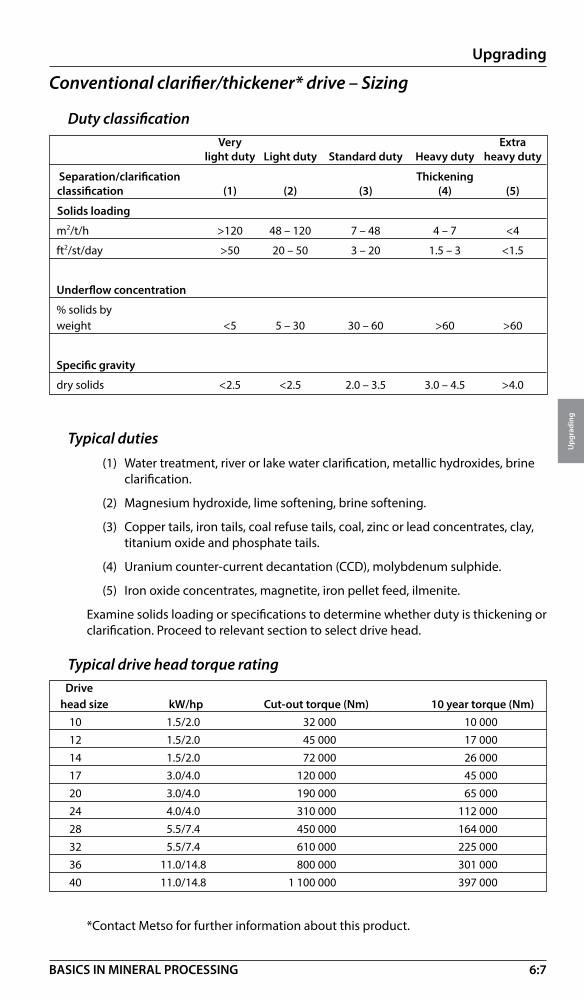
6:7
Upgrading
Upg
radi
ng
BASICS IN MINERAL PROCESSING
Conventional clarifier/thickener* drive – Sizing
Duty classification Very Extra
light duty Light duty Standard duty Heavy duty heavy duty
Separation/ clarification Thickeningclassification (1) (2) (3) (4) (5)
Solids loading
m2/t/h >120 48 – 120 7 – 48 4 – 7 <4
ft2/st/day >50 20 – 50 3 – 20 1.5 – 3 <1.5
Underflow concentration
% solids byweight <5 5 – 30 30 – 60 >60 >60
Specific gravity
dry solids <2.5 <2.5 2.0 – 3.5 3.0 – 4.5 >4.0
Typical duties (1) Water treatment, river or lake water clarification, metallic hydroxides, brine
clarification.
(2) Magnesium hydroxide, lime softening, brine softening.
(3) Copper tails, iron tails, coal refuse tails, coal, zinc or lead concentrates, clay, titanium oxide and phosphate tails.
(4) Uranium counter-current decantation (CCD), molybdenum sulphide.
(5) Iron oxide concentrates, magnetite, iron pellet feed, ilmenite.
Examine solids loading or specifications to determine whether duty is thickening or clarification. Proceed to relevant section to select drive head.
Typical drive head torque rating Drive head size kW/hp Cut-out torque (Nm) 10 year torque (Nm) 10 1.5/2.0 32 000 10 000 12 1.5/2.0 45 000 17 000 14 1.5/2.0 72 000 26 000 17 3.0/4.0 120 000 45 000 20 3.0/4.0 190 000 65 000 24 4.0/4.0 310 000 112 000 28 5.5/7.4 450 000 164 000 32 5.5/7.4 610 000 225 000 36 11.0/14.8 800 000 301 000 40 11.0/14.8 1 100 000 397 000
*Contact Metso for further information about this product.

6:8
Upgrading
Upg
radi
ng
BASICS IN MINERAL PROCESSING
Clarifier drive selectionClarifiers, see duty page 6:8, operate with a low solids loading and drives are selected according to formula below
Tc = KxD2
Tc = Process Cut Off torque (Nm)K = Clarifier duty factor (see below)D = Clarifier Diameter (m)
Duty factor
Select a drive head from the” Drive Head Torque” values above, so that the specified “cut out torque” is greater then calculated Tc.
Example: Select a bridge mounted drive head for a 35 m diameter clarifier (no lift required). Application: lime sludge clarifying.
K factor = 210 giving a Tc = 210 x 35² = 257 250 Nm. Select a drive head type BN 24, cut out torque 310 000 Nm.
Thickener drive selectionHere we are calculating with Process Equivalent Torque (or 10 year torque).
Te = 256 x D x √MTe = Process Equivalent TorqueD = Thickener diameter (m)M = Solids in underflow (tph), see duty above
Select a drive head from the “Drive Head Torque” values above, so that the 10 year torque is greater than Te calculated above.
Example: Select a pier mounted drive head with a lift suitable for a 50 m dia- meter thickener handling an underflow of 130 tph of solids.
Te = 256 x 50 x √130 = 145 952 Nm. Select CL 28 drive head with a 10 year torque of 164 000 Nm.
Clarifying application Duty factorBrine purification 60Lime softening 80Metal hydroxides 150-200Lime sludge 210Pulp and paper sludge 250Metall works process water 200-250Gas cleaning water 350Heat treatment (metal) sludge 440

6:9
Upgrading
Upg
radi
ng
BASICS IN MINERAL PROCESSING
Lamella plates
Particles between the inclined plates migrate to each plate surface along the resultant vector of thetwo forces - fluid drag (Fl) and gravity (Fg).
Once on the plates, the particles slide down to
discharge into the thickening zone.
Water & solidsFI
Fg Fluid drag: FIGravity: Fg
Metso’s inclined plate principle uses several parallel inclined plates to maximise the available area for any floor area. In this way, the size and cost of the gravity settler can be minimised by matching the thickening and clarifying requirements more closely.
The two basic criteria for gravity settling equipment are good clarity of the over flow liquid and maximum density of the underflow solids discharge.
The area required to clarify a suspension is often greater than that needed for thickening.
This means that in a cylindrical thickening tank, the lower section with rakes and drive mechanism can be oversized.
Clarification is achieved when upstream velocity is low enough to allow solids to report to the inclined plate.
Inclined plate thickening is achieved as primary thickening on the lamella plates and secondary thickening and compression in the lower inclined plate tank.
Inclined plate sedimentation – Introduction

6:10
Upgrading
Upg
radi
ng
BASICS IN MINERAL PROCESSING
Inclined plates – principleThe clarifiers and thickeners are utilising the “Inclined plate principle” to perform sedimentation processes in much more compact equipment than would be possible using conventional techniques. Some typical comparisons of floor area requirements are given below (for clarification applications):
The inclined plate concept offers many practical advantages:
• Reduced plant area requirements• Reduced retention time• Possibility to optimize the ratio of clarification & thickening area• Low heat losses – easy to insulate• Low water losses due to evaporation – easy to cover• Transport of the unit is more practical• More suitable for indoor installation• Quicker installation• Easier to manufacture special designs (rubber lined, stainless steel etc.)• Lower capital costs
There are limitations to the “inclined plate concept” and in some of these cases conventional thickeners can be preferred. Examples are:
• High surface loads (above approx. 5.0 m3/m2h (0.28 ft3/ft2min)• Feeds with very high solids content / sludge volumes• High froth content (flotation concentrates)
Inclined plates – functionThe area above the feed points is regarded as clarification area (Acl), this can be up to 80% of the total plate area. The area beneath the feed point is thickening area (Ath), this can be up to 50% of the total plate area.

6:11
Upgrading
Upg
radi
ng
BASICS IN MINERAL PROCESSING
Inclined Plate Settler – IPS
DesignThe inclined plate settler consists of two main compo nents, the upper tank containing the inclined plates, inclined at 55°, and the lower conical or cylindrical sludge container.
The feed for the inclined plate settler enters through vertical chambers on either side of the plate packs and passes into each plate gap through slotted feed ports. Clarification takes place above the suspension inlet so there is no mixing of the clarified fluid with the incoming feed.
Above each pack is a full-length overflow launder fitted with throttling holes to create a slight hydraulic back pressure on the incoming feed stream. This method of feed control guarantees equal distribution to all inclined plate chambers with minimum turbulence at the entry points.
The solids settle onto and slide down each plate to the sludge container where the solids are further thickened and compressed with the assistance of the raking system.
Feed inlet
Flocculationagitator
Inclinedplate pack
Sludge hopper
Rake
Overflow outlet
Overflow launders
Flocculationagitator
Rake drive with lift (optional)
Underflow outlet

6:12
Upgrading
Upg
radi
ng
BASICS IN MINERAL PROCESSING
Inclined Plate Settler – Drives
Design 1. Gear motor 2. Planetary gear 3. Screw jack 4. Frame
Sizes Max. operating Cut - out Power Lifting Drive unit torque torque range capacitysize (Nm) (ft lbs) (Nm) (ft lbs) (kW) (hp) (kN) (lbf)SFL 02 2 000 1 475 2 700 1 990 0.18 – 0.75 1/4 – 1 50 11 240
SFL 05 5 000 3 690 6 750 5 000 0.37 – 2.2 1/2 – 3 50 11 240
SFL 10 10 000 7 380 13 500 9 956 0.37 – 5.5 1/2 – 71/2 50 11 240
SFL 20 20 000 14 760 27 000 19 900 0.55 – 4.0 3/4 – 5 50 11 240
SFL 30 30 000 22 140 40 500 29 900 0.75 – 5.5 1 – 71/2 50 11 240
SFL 60 60 000 44 255 80 000 59 005 0.75 – 5.5 1 – 71/2 100 22 480
SFL 80 80 000 59 000 108 000 79 655 3-5,5 4-7,5 100 22 480
SFL 100 100 000 73 755 135 000 99 550 3’-4 4-5,5 100 22 480
SFL 130 130 000 95 885 175 500 129 440 4-5,5 5,5-7,5 150 33 720
Lifting sequencesDefinition: 100% load equal to max torque recommended by supplier.
Load Function
< 50% Normal operation with rakes in lower position.
> 75% Rakes are lifted until 100% load is reached. Rakes stay in upper position until 70% is reached, then lowering towards bottom position.
> 100% Cut-out torque stops rotation of rakes. Lifting to the top position and alarm. Starts up normally from drive head control panel.
Control panel• PLC controlled• Fully automatic incl. functions for:
– Speed control of flocculator– Torque signal– Start and stop sequences– Alarm indications for levels, flows etc.
– Control of underflow valve and pump
1 1
2
3
2
3
4

6:13
Upgrading
Upg
radi
ng
BASICS IN MINERAL PROCESSING
Inclined Plate Settler – Product range
Type LTO• Sizes up to 400 m2 (4 305 ft2) effective
clarification area (500 m² total projected area)
• Effective also with coarser material
• Limited solids content in feed
• Extension of lower part as option
• Lifting device as option
Type LTS• Sizes up to 400 m2 (4 305 ft2) effective
clarification area (500 m² total projected area)
• Not suitable for coarse material (> 0.5-1 mm, 32 – 16 Mesh)
• Higher solids load
• Extension of lower part as option
• Lifting device as option
Type LTK• Sizes up to 400 m2 (4 305 ft2) effective
clarification area (500 m² total projected area)
• For higher solids load
• Used when storage and thickening is critical
• Extension of lower part as option
• Lifting device as standard
See also data sheet 6:16.
See also data sheet 6:17.
See also data sheet 6:18.

6:14
Upgrading
Upg
radi
ng
BASICS IN MINERAL PROCESSING
Type LTO, LTS, LTK with extended tank• By lower tank extensions the volume can be
increased giving better storage and improved thickening.
Type combi LTC• Sizes up to tank dia 24 m (78.7 ft) =
400 m2 (53 800 ft2)
• For light and heavy duties
• High storage capacity
• Improved thickening
• Plate or concrete tank
• Conventional thickener drives
See also data sheet 6:21.
“Combi IPS” built up by using inclined plate packs in circular tanks have principally no limitation in sizes.
From design point, however, max. practical area for each plate pack unit is approx. 5 400 m2. These sizes can then be combined in modules 5 400 m2 + 5 400 m2 + ... (58 125 ft 2+ 58 1250 ft 2 + ...)
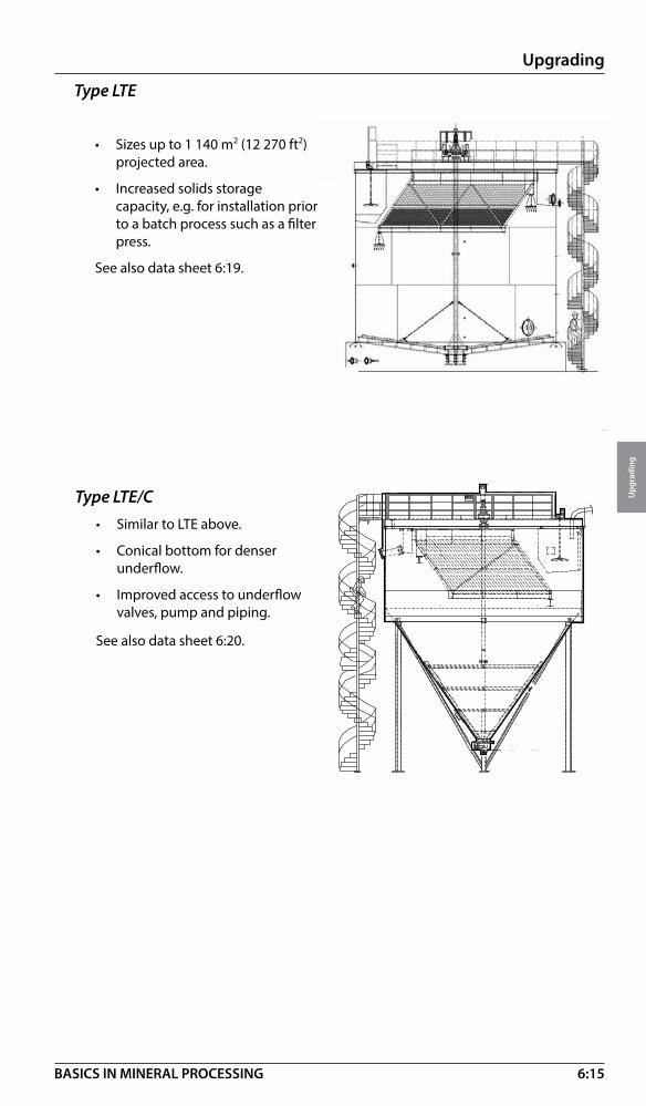
6:15
Upgrading
Upg
radi
ng
BASICS IN MINERAL PROCESSING
�
�����������
�
���
Type LTE/C• Similar to LTE above.
• Conical bottom for denser underflow.
• Improved access to underflow valves, pump and piping.
See also data sheet 6:20.
Type LTE
• Sizes up to 1 140 m2 (12 270 ft2) projected area.
• Increased solids storage capacity, e.g. for installation prior to a batch process such as a filter press.
See also data sheet 6:19.
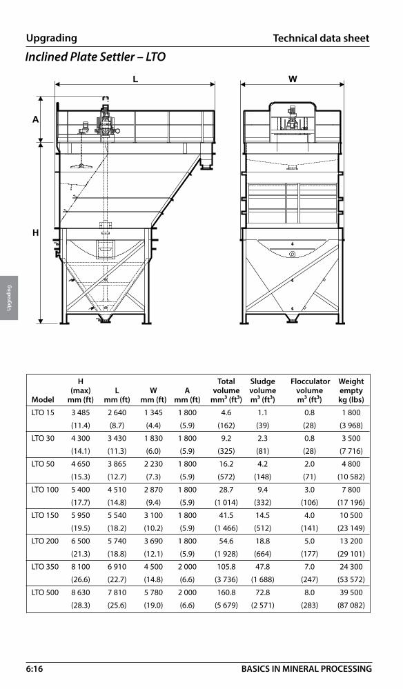
6:16
Upgrading
Upg
radi
ng
BASICS IN MINERAL PROCESSING
Technical data sheet
Inclined Plate Settler – LTO
H Total Sludge Flocculator Weight (max) L W A volume volume volume emptyModel mm (ft) mm (ft) mm (ft) mm (ft) mm³ (ft³) m³ (ft³) m³ (ft³) kg (lbs)
LTO 15 3 485 2 640 1 345 1 800 4.6 1.1 0.8 1 800
(11.4) (8.7) (4.4) (5.9) (162) (39) (28) (3 968)
LTO 30 4 300 3 430 1 830 1 800 9.2 2.3 0.8 3 500
(14.1) (11.3) (6.0) (5.9) (325) (81) (28) (7 716)
LTO 50 4 650 3 865 2 230 1 800 16.2 4.2 2.0 4 800
(15.3) (12.7) (7.3) (5.9) (572) (148) (71) (10 582)
LTO 100 5 400 4 510 2 870 1 800 28.7 9.4 3.0 7 800
(17.7) (14.8) (9.4) (5.9) (1 014) (332) (106) (17 196)
LTO 150 5 950 5 540 3 100 1 800 41.5 14.5 4.0 10 500
(19.5) (18.2) (10.2) (5.9) (1 466) (512) (141) (23 149)
LTO 200 6 500 5 740 3 690 1 800 54.6 18.8 5.0 13 200
(21.3) (18.8) (12.1) (5.9) (1 928) (664) (177) (29 101)
LTO 350 8 100 6 910 4 500 2 000 105.8 47.8 7.0 24 300
(26.6) (22.7) (14.8) (6.6) (3 736) (1 688) (247) (53 572)
LTO 500 8 630 7 810 5 780 2 000 160.8 72.8 8.0 39 500
(28.3) (25.6) (19.0) (6.6) (5 679) (2 571) (283) (87 082)
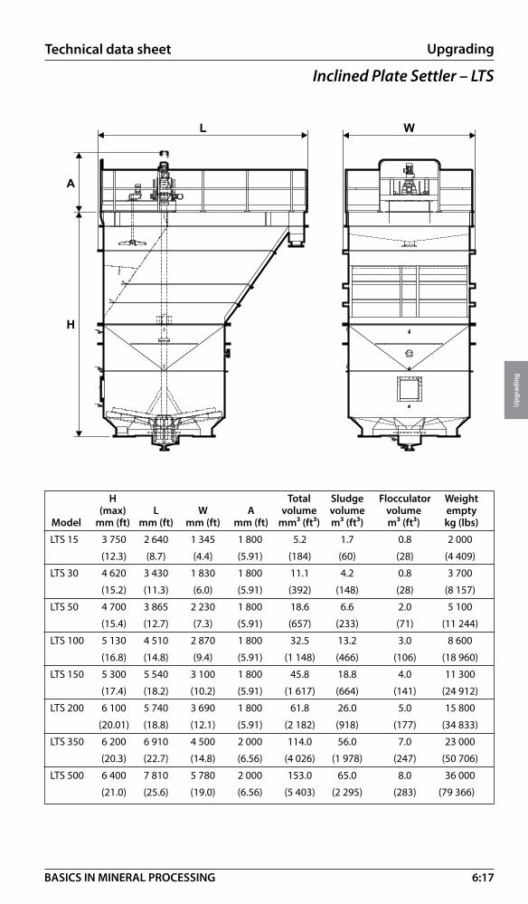
6:17
Upgrading
Upg
radi
ng
BASICS IN MINERAL PROCESSING
Inclined Plate Settler – LTS
H Total Sludge Flocculator Weight (max) L W A volume volume volume empty Model mm (ft) mm (ft) mm (ft) mm (ft) mm³ (ft³) m³ (ft³) m³ (ft³) kg (lbs)
LTS 15 3 750 2 640 1 345 1 800 5.2 1.7 0.8 2 000
(12.3) (8.7) (4.4) (5.91) (184) (60) (28) (4 409)
LTS 30 4 620 3 430 1 830 1 800 11.1 4.2 0.8 3 700
(15.2) (11.3) (6.0) (5.91) (392) (148) (28) (8 157)
LTS 50 4 700 3 865 2 230 1 800 18.6 6.6 2.0 5 100
(15.4) (12.7) (7.3) (5.91) (657) (233) (71) (11 244)
LTS 100 5 130 4 510 2 870 1 800 32.5 13.2 3.0 8 600
(16.8) (14.8) (9.4) (5.91) (1 148) (466) (106) (18 960)
LTS 150 5 300 5 540 3 100 1 800 45.8 18.8 4.0 11 300
(17.4) (18.2) (10.2) (5.91) (1 617) (664) (141) (24 912)
LTS 200 6 100 5 740 3 690 1 800 61.8 26.0 5.0 15 800
(20.01) (18.8) (12.1) (5.91) (2 182) (918) (177) (34 833)
LTS 350 6 200 6 910 4 500 2 000 114.0 56.0 7.0 23 000
(20.3) (22.7) (14.8) (6.56) (4 026) (1 978) (247) (50 706)
LTS 500 6 400 7 810 5 780 2 000 153.0 65.0 8.0 36 000
(21.0) (25.6) (19.0) (6.56) (5 403) (2 295) (283) (79 366)
Technical data sheet

6:18
Upgrading
Upg
radi
ng
BASICS IN MINERAL PROCESSING
Technical data sheet
Inclined Plate Settler – LTK
Total Sludge Flocculator Weight H L W A volume volume volume empty Model mm (ft) mm (ft) mm (ft) mm (ft) mm³ (ft³) m³ (ft³) m³ (ft³) kg (lbs)
LTK 15 5 100 2 795 1 610 1 800 8.0 4.5 0.8 2 200
(16.7) (9.2) (5.3) (5.9) (283) (159) (28) (4 850)
LTK 30 4 550 3 690 2 310 1 800 14.5 7.6 0.8 4 500
(14.9) (12.11) (7.6) (5.9) (512) (268) (28) (9 921)
LTK 50 4 800 4 170 2 810 1 800 23.5 11.5 2.0 6 200
(15.7) (13.7) (9.2) (5.9) (830) (406) (71) (13 669)
LTK 100 5 390 5 020 3 715 1 800 45.5 26.2 3.0 10 100
(17.7) (16.5) (12.2) (5.9) (1 607) (925) (106) (22 267)
LTK 150 5 800 5 885 4 490 1 800 61.0 34.0 4.0 13 000
(19.0) (19.3) (14.7) (5.9) (2 154) (1 201) (141) (28 660)
LTK 200 6 500 6 235 4 715 1 800 87.0 51.2 5.0 16 500
(21.3) (20.6) (15.5) (5.9) (3 072) (1 808) (177) (36 376)
LTK 350 6 930 7 485 6 220 2 000 143.0 85.0 7.0 26 500
(22.7) (24.6) (20.4) (6.6) (5 050) (3 002) (247) (58 422)
LTK 500 6 940 8 705 7 520 2 000 200.0 112.0 8.0 46 500
(22,8) (28,6) (24,7) (6,6) (7 063) (3 955) (283) (102 515)

6:19
Upgrading
Upg
radi
ng
BASICS IN MINERAL PROCESSING
Inclined Plate Settler – LTE
Settling area Tank dia (D) Tank height (H) Sludge volume Total volume Model m2 (ft2) mm (ft) mm (ft) m3 (ft3) m3 (ft3)
LTE 220-6.3 220 (2 386) 6 300 (20.7) 6 000 (19.7) 86 (3 040) 192 (6 780)
9 000 (29.5) 179 (6 320) 285 (10 065)
LTE 275-7.1 275 (2 960) 7 100 (23.3) 6 000 (19.7) 110 (3 885) 244 (8 629)
9 000 (29.5) 228 (8 050) 363 (12 820)
LTE 440-8.3 440 (4736) 8 300 (27.0) 6 000 (19.7) 151 (5 335) 335 (11 830)
9 000 (29.5) 314 (11 090) 497 (17 550)
12 000 (39.4) 476 (16 810) 660 (23 310)
LTE 550-9.0 550 (5 920) 9 000 (29.5) 6 000 (19.7) 179 (6 320) 395 (13 950)
9 000 (29.5) 370 (13 065) 586 (20 695)
12 000 (39.4) 561 (19 810) 777 (27 440)
LTE800-10.5 800 (8 611) 10 500 (34.4) 6 000 (19.7) 246 (8 690) 541 (19 105)
9 000 (29.5) 506 (17 870) 801 (28 290)
12 000 (39.4) 766 (27 050) 1 060 (37 435)
LTE 1140 1 140 (12 270) 12 000 (39.4) 6 000 (19.7) 326 (11 510) 710 (25 0705)
9 000 (29.5) 665 (23 480) 1 050 (37 080)
12 000 (39.4) 1004 (35 4555) 1 389 (49 050)
Technical data sheet
1,5 - 2,5 m
4.5 - 7.5 ft
D
H
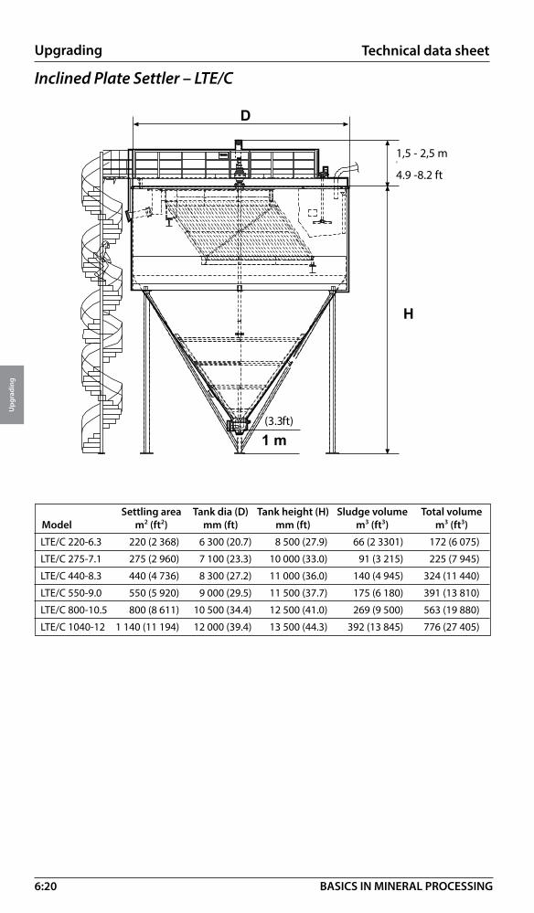
6:20
Upgrading
Upg
radi
ng
BASICS IN MINERAL PROCESSING
Technical data sheet
�
�����������
�
���
Inclined Plate Settler – LTE/C
(3.3 ft)
1,5 - 2,5 m
4.9 -8.2 ft
Settling area Tank dia (D) Tank height (H) Sludge volume Total volume Model m2 (ft2) mm (ft) mm (ft) m3 (ft3) m3 (ft3)
LTE/C 220-6.3 220 (2 368) 6 300 (20.7) 8 500 (27.9) 66 (2 3301) 172 (6 075)
LTE/C 275-7.1 275 (2 960) 7 100 (23.3) 10 000 (33.0) 91 (3 215) 225 (7 945)
LTE/C 440-8.3 440 (4 736) 8 300 (27.2) 11 000 (36.0) 140 (4 945) 324 (11 440)
LTE/C 550-9.0 550 (5 920) 9 000 (29.5) 11 500 (37.7) 175 (6 180) 391 (13 810)
LTE/C 800-10.5 800 (8 611) 10 500 (34.4) 12 500 (41.0) 269 (9 500) 563 (19 880)
LTE/C 1040-12 1 140 (11 194) 12 000 (39.4) 13 500 (44.3) 392 (13 845) 776 (27 405)
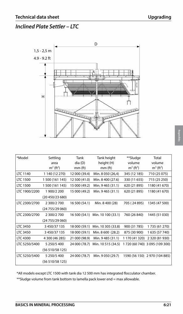
6:21
Upgrading
Upg
radi
ng
BASICS IN MINERAL PROCESSING
Technical data sheet
Inclined Plate Settler – LTC
*Model Settling Tank Tank height **Sludge Total area dia (D) height (H) volume volume m2 (ft2) mm (ft) mm (ft) m3 (ft3) m3 (ft3)
LTC 1140 1 140 (12 270) 12 000 (39.4) Min. 8 050 (26,4) 345 (12 185) 710 (25 075)
LTC 1500 1 500 (161 145) 12 500 (41.0) Min. 8 400 (27.6) 330 (11 655) 715 (25 250)
LTC 1500 1 500 (161 145) 15 000 (49.2) Min. 9 465 (31.1) 620 (21 895) 1180 (41 670)
LTC 1900/2200 1 900/2 200 15 000 (49.2) Min. 9 465 (31.1) 620 (21 895) 1180 (41 670)
(20 450/23 680)
LTC 2300/2700 2 300/2 700 16 500 (54.1) Min. 8 400 (28) 705 ( 24 895) 1345 (47 500)
(24 755/29 060)
LTC 2300/2700 2 300/2 700 16 500 (54.1) Min. 10 100 (33.1) 760 (26 840) 1445 (51 030)
(24 755/29 060)
LTC 3450 3 450/37 135 18 000 (59.1) Min. 10 305 (33.8) 900 (31 785) 1 735 (61 270)
LTC 3450 3 450/37 135 18 000 (59.1) Min. 8 600 (28.2) 875 (30 900) 1 635 (57 740)
LTC 4300 4 300 (46 285) 21 000 (98.9) Min. 9 485 (31.1) 1 170 (41 320) 2 320 (81 930)
LTC 5250/5400 5 250/5 400 24 000 (78.7) Min. 10 515 (34.5) 1 720 (60 740) 3 095 (109 300)
(56 510/58 125)
LTC 5250/5400 5 250/5 400 24 000 (78.7) Min. 9 050 (29.7) 1590 (56 150) 2 970 (104 885)
(56 510/58 125)
*All models except LTC 1500 with tank dia 12 500 mm has integrated flocculator chamber.
**Sludge volume from tank bottom to lamella pack lower end = max allowable.
1,5 - 2,5 m
4.9 - 9.2 ft
D
H

6:22
Upgrading
Upg
radi
ng
BASICS IN MINERAL PROCESSING
PRESSUREFILTERS
VACUUM FILTERS
TUBE PRESSES
DEWATERING SCREENSDEWATERING SPIRALS
Size 1m 1 dm 1 cm 1 mm 100 micron 10 micron 1 micron
Mechanical dewatering – IntroductionMechanical dewatering means mechanical removal of liquids from a slurry to obtain the solids in a suitable form and/or recovery of a valueable liquid for:
• Further processing
• Transportation
• Agglomeration
• Disposal
• Recovery of valuable liquids
Mechanical dewatering – Methods and products
Medium pressure dewatering
• Air pressure filters (compression and through-blow)
High pressure dewatering
• Tube presses (compression and air-purged)
High pressure
Medium press.
Low pressure
Gravimetric
p
Gravimetric dewatering
• Dewatering spirals (not covered)
• Dewatering screens
• Dewatering wheels (not covered)
Low pressure dewatering
• Drum vacuum filters
• Belt drum vacuum filters
• Top feed vacuum filters
• Disc vacuum filters (not covered)
• Horizontal belt vacuum filters (not covered)
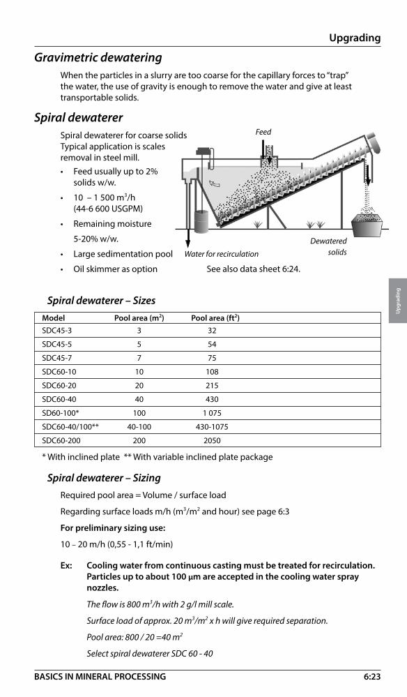
6:23
Upgrading
Upg
radi
ng
BASICS IN MINERAL PROCESSING
Spiral dewaterer – SizesModel Pool area (m2) Pool area (ft2)SDC45-3 3 32
SDC45-5 5 54
SDC45-7 7 75
SDC60-10 10 108
SDC60-20 20 215
SDC60-40 40 430
SD60-100* 100 1 075
SDC60-40/100** 40-100 430-1075
SDC60-200 200 2050
* With inclined plate ** With variable inclined plate package
Spiral dewaterer – SizingRequired pool area = Volume / surface load
Regarding surface loads m/h (m3/m2 and hour) see page 6:3
For preliminary sizing use:
10 – 20 m/h (0,55 - 1,1 ft/min)
Ex: Cooling water from continuous casting must be treated for recirculation. Particles up to about 100 µm are accepted in the cooling water spray nozzles.
The flow is 800 m3/h with 2 g/l mill scale.
Surface load of approx. 20 m3/m2 x h will give required separation.
Pool area: 800 / 20 =40 m2
Select spiral dewaterer SDC 60 - 40
Gravimetric dewateringWhen the particles in a slurry are too coarse for the capillary forces to “trap” the water, the use of gravity is enough to remove the water and give at least transportable solids.
Spiral dewatererSpiral dewaterer for coarse solids Typical application is scales removal in steel mill. • Feed usually up to 2%
solids w/w.
• 10 – 1 500 m3/h (44-6 600 USGPM)
• Remaining moisture
5-20% w/w.
• Large sedimentation pool
• Oil skimmer as option
Feed
Water for recirculation
Dewateredsolids
See also data sheet 6:24.
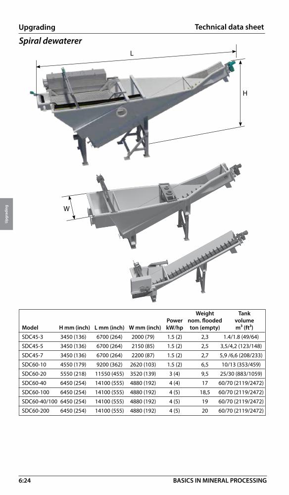
6:24
Upgrading
Upg
radi
ng
BASICS IN MINERAL PROCESSING
Weight Tank Power nom. flooded volumeModel H mm (inch) L mm (inch) W mm (inch) kW/hp ton (empty) m³ (ft³)
SDC45-3 3450 (136) 6700 (264) 2000 (79) 1.5 (2) 2,3 1.4/1.8 (49/64)
SDC45-5 3450 (136) 6700 (264) 2150 (85) 1.5 (2) 2,5 3,5/4,2 (123/148)
SDC45-7 3450 (136) 6700 (264) 2200 (87) 1.5 (2) 2,7 5,9 /6,6 (208/233)
SDC60-10 4550 (179) 9200 (362) 2620 (103) 1.5 (2) 6,5 10/13 (353/459)
SDC60-20 5550 (218) 11550 (455) 3520 (139) 3 (4) 9,5 25/30 (883/1059)
SDC60-40 6450 (254) 14100 (555) 4880 (192) 4 (4) 17 60/70 (2119/2472)
SDC60-100 6450 (254) 14100 (555) 4880 (192) 4 (5) 18,5 60/70 (2119/2472)
SDC60-40/100 6450 (254) 14100 (555) 4880 (192) 4 (5) 19 60/70 (2119/2472)
SDC60-200 6450 (254) 14100 (555) 4880 (192) 4 (5) 20 60/70 (2119/2472)
Technical data sheet
W
Spiral dewaterer
H
L

6:25
Upgrading
Upg
radi
ng
BASICS IN MINERAL PROCESSING
Feed
Sanddischarge
Washwater
Sand screw*This is a simpler version of the spiral dewaterer mainly used for natural sand. These sands are normally classified (particles below 10 – 50 micron are removed) meaning that the sedimentation pool is very limited compared to the spiral dewaterer.
Dewatering screen*This is a version of a screen in linear motion moving the solids upwards on an inclined plane at an inclination of 5o. Dewatering takes place in the moving sand bed. Only for sand, coal or other deslimed solids.
Linearmotion
Dis-charge
Dewatering
Primarydrainage
Feed
Dewatering wheel*The dewatering wheel is mainly used in dredging of natural sand and gravel. The machine has a simple water draining arrangement at the sand removal buckets. Therefore the water content can be reduced down to 15-18 % H2O by weight even if the feed contains certain fines. The pool is limited meaning that the machine is sensitive to high volume flows.
*Not available from Metso.

6:26
Upgrading
Upg
radi
ng
BASICS IN MINERAL PROCESSING
For vacuum filters air-through blow is used
For vertical plate pressure filters either compression or a combination of compression and air through-blow is used
For tube presses either compression or a combination of compression and air-purge (air through blow) is used. The Tube Press also enables cake washing.
Drum vacuum filtersVacuum filtration is the simplest form of “through blow” dewatering. A pressure differential created by a vacuum applied to the inside of the filter drum causes air to flow through the filter cake thereby displacing the contained water. The solids are retained on a filter cloth and are carried to discharge point by the rotation of the drum.
Drum filter 1. Drum – filter cloth mounted on segment
grids. Internal drainage pipes.2. Drum drive – variable speed 3. Support frame 4. Tank 5. Vacuum head – seal arrangement
to connect rotating drum to stationary vacuum piping
6. Agitator – to suspend solid particles in tank
Mechanical dewatering by pressure – IntroductionAs particles get finer the resistance against removing water increases. Gravity dewatering can no longer be used. Pressure has to be applied.By creating a differential pressure ∆p across a cake of solids, liquid can be removed by
Compression
“Dewatering by compression means replacing the liquid in a cake with particles”
Through blow
“Dewatering by through-blow means replacing the water in a cake with air”
Cake wash can be applied to any of these filters
1.
2.
5.
3.
4.6.
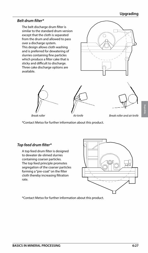
6:27
Upgrading
Upg
radi
ng
BASICS IN MINERAL PROCESSING
Belt drum filter*The belt discharge drum filter is similar to the standard drum version except that the cloth is separated from the drum and allowed to pass over a discharge system.This design allows cloth washing and is preferred for dewatering of slurries containing fine particles which produce a filter cake that is sticky and difficult to discharge. Three cake discharge options are available.
Break roller Air knife Break roller and air knife
*Contact Metso for further information about this product.
Top feed drum filter*A top feed drum filter is designed to dewater de-slimed slurries containing coarser particles.The top feed principle promotes segregation of the coarser particles forming a “pre-coat” on the filter cloth thereby increasing filtration rate.
*Contact Metso for further information about this product.

6:28
Upgrading
Upg
radi
ng
BASICS IN MINERAL PROCESSING
Vacuum filters – Vacuum requirement
PrincipleBy evacuating the air inside the filters dewatering can be achieved by air “through-blow”.
Vacuum requirement is calculated as the volume of thinned air per effective filter surface area per minute.
Thinned air volume is volume at actual reduced pressure.
Free air volume (used for sizing of compressors) is the volume at normal atmospheric pressure.
10 m
10
Vacuum plant – Arrangement
1. Vacuum receiver
2. Moisture trap*
3. Vacuum pump
4. Liquid separator
5. Silencer
6. Filtrate pump
7. Floor drain
For plants without filtrate pump also:
8. Drain line from vacuum tank (barometric leg)
9. Water lock
10. Non-return valve
* Normally used for aggressive filtrates only.

6:29
Upgrading
Upg
radi
ng
BASICS IN MINERAL PROCESSING
Vertical plate pressure filter – IntroductionThe pressure filter model VPA is of “medium pressure” type operating in the pressure range of 6 –10 bar. The machine mainly relies on the “air through blow” dewatering concept, whereby water is displaced by air as it passes through a filter cake.
Air penetration through a pore system
The driving force of this filtration method is the pressure differential across the cake. A higher pressure drop will give a faster dewatering rate and a lower residual moisture, as smaller voids are emptied from liquid.

6:30
Upgrading
Upg
radi
ng
BASICS IN MINERAL PROCESSING
PretreatmentFor optional results of filter operation the pulp fed to the machine should be as high in solids as possible.
Dewatering cycleStart position
Vertical plate pressure filter – Design
• VPA = Vertical Pressure Filter Air through blow • Lightweight polypropylene filter plates are mounted on a bolted steel frame
and are moved by hydraulic cylinders • Adjacent “filter and compression” plates form a filtration chamber. The filter
cloths hang between each pair of plates. Rubber membranes are protected by the filter cloth thereby reducing wear.
• By mounting the filter on a load cell system the filtration cycle is monitored and controlled.
• Chambers are top fed for optimum filling. Two sided filtration speeds up the “filling” cycle.
• Openings for pulp, water and air are generously dimensioned to reduce energy losses and wear
• Service and maintenance requirements are low. The VPA design facilitates easy cloth changing.
• Air blow pressure 5 – 8 bar (73 –116 psi). Membrane pressure 8 – 10 bar (116-145 psi)
Pressure filter VPA – Operation
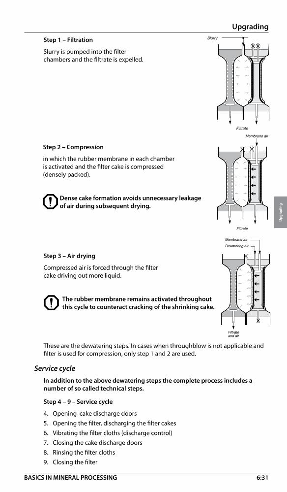
6:31
Upgrading
Upg
radi
ng
BASICS IN MINERAL PROCESSING
Step 2 – Compression
in which the rubber membrane in each chamber is activated and the filter cake is compressed (densely packed).
Dense cake formation avoids unnecessary leakage of air during subsequent drying.
These are the dewatering steps. In cases when throughblow is not applicable and filter is used for compression, only step 1 and 2 are used.
Service cycleIn addition to the above dewatering steps the complete process includes a number of so called technical steps.
Step 4 – 9 – Service cycle
4. Opening cake discharge doors5. Opening the filter, discharging the filter cakes6. Vibrating the filter cloths (discharge control)7. Closing the cake discharge doors8. Rinsing the filter cloths9. Closing the filter
Step 3 – Air drying
Compressed air is forced through the filter cake driving out more liquid.
The rubber membrane remains activated throughout this cycle to counteract cracking of the shrinking cake.
Step 1 – Filtration
Slurry is pumped into the filter chambers and the filtrate is expelled.

6:32
Upgrading
Upg
radi
ng
BASICS IN MINERAL PROCESSING
Pressure filter VPA – NomenclatureFilter model VPA 10XX-YY VPA 15XX-YY VPA 20XX-YY
Filter size 10 15 20
Chamber depth XX mm XX mm XX mm
No. of chambers YY YY YY
Pressure filter VPA – Technical data
Number of chambers VPA 10 VPA 15 VPA 20 8 – 40 20 – 60 32 – 62Main dimensions Overall length mm 6585 – 10815 9340 – 15640 14090 – 18890 Overall width mm 2450 3600 5250 Overall height mm 2370 3360 4530 Installed power (hydraulics) High Pressure pump (in operation at all time) kW 11 22 30
Low Pressure pumps(only in operation during kW 22 55 75opening/closing)
The technical data is subject to change without notice
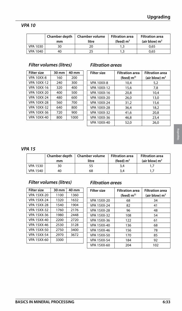
6:33
Upgrading
Upg
radi
ng
BASICS IN MINERAL PROCESSING
VPA 10 Chamber depth Chamber volume Filtration area Filtration area mm litre (feed) m2 (air blow) m2
VPA 1030 30 20 1,3 0,65VPA 1040 40 25 1,3 0,65
Filtration areasFilter size Filtration area Filtration area (feed) m2) (air blow) m2
VPA 10XX-8 10,4 5,2VPA 10XX-12 15,6 7,8VPA 10XX-16 20,8 10,4VPA 10XX-20 26,0 13,0VPA 10XX-24 31,2 15,6VPA 10XX-28 36,4 18,2VPA 10XX-32 41,6 20,8VPA 10XX-36 46,8 23,4VPA 10XX-40 52,0 26,0
Filter volumes (litres)Filter size 30 mm 40 mmVPA 10XX-8 160 200VPA 10XX-12 240 300VPA 10XX-16 320 400VPA 10XX-20 400 500VPA 10XX-24 480 600VPA 10XX-28 560 700VPA 10XX-32 640 800VPA 10XX-36 720 900VPA 10XX-40 800 1000
VPA 15 Chamber depth Chamber volume Filtration area Filtration area mm litre (feed) m2 (air blow) m2
VPA 1530 30 55 3,4 1,7VPA 1540 40 68 3,4 1,7
Filtration areasFilter size Filtration area Filtration area (feed) m2) (air blow) m2
VPA 15XX-20 68 34VPA 15XX-24 82 41VPA 15XX-28 96 48VPA 15XX-32 108 54VPA 15XX-36 122 61VPA 15XX-40 136 68VPA 15XX-46 156 78VPA 15XX-50 170 85VPA 15XX-54 184 92VPA 15XX-60 204 102
Filter volumes (litres)Filter size 30 mm 40 mmVPA 15XX-20 1100 1360VPA 15XX-24 1320 1632VPA 15XX-28 1540 1904VPA 15XX-32 1760 2176VPA 15XX-36 1980 2448VPA 15XX-40 2200 2720VPA 15XX-46 2530 3128VPA 15XX-50 2750 3400VPA 15XX-54 2970 3672VPA 15XX-60 3300

6:34
Upgrading
Upg
radi
ng
BASICS IN MINERAL PROCESSING
Filtration areasFilter size Filtration area Filtration area (feed) m2) (air blow) m2
VPA 20XX-32 249,6 124,8VPA 20XX-36 280,8 140,4VPA 20XX-40 312,0 156,0VPA 20XX-46 358,8 179,4VPA 20XX-50 390,0 195,0VPA 20XX-54 421,2 210,6VPA 20XX-56 436,8 218,4VPA 20XX-60 468,0 234,0VPA 20XX-62 483,6, 241,8
VPA 20 Chamber depth Chamber volume Filtration area Filtration area mm litre (feed) m2 (air blow) m2
VPA 2040 40 169 7,8 3,9VPA 2050 50 205 7,8 3,9
Filter volumes (litres)Filter size 40 mm 50 mmVPA 20XX-32 5408 6560VPA 20XX-36 6084 7380VPA 20XX-40 6760 8200VPA 20XX-46 7774 9430VPA 20XX-50 N/A 10250VPA 20XX-54 9126 N/AVPA 20XX-56 N/A 11480VPA 20XX-60 10140 N/AVPA 20XX-62 N/A 12710VPA 20XX-66 11154 N/A

6:35
Upgrading
Upg
radi
ng
BASICS IN MINERAL PROCESSING
Pressure filter VPA – SizingWe are using the cycle method:
1. Cake bulk weights Specific dry weight of the filter cake inside each chamber is called the cake bulk weight (kg/liter or lb/ft3)
Approximate cake bulk weights (ρcake) usually about 60% of specific gravity.
Material kg/dm3 lb/ft3
Cu-conc (80%-45 micron) 2.2 137Pb-conc (80%-40 micron) 3.1 193Zn-conc (80%-30 micron) 2.1 131Magnetite conc. (80%-x micron) 3.0 187Coal 0.9 56Chalk 1.3 81
2. Plant capacityBy dividing the required throughput S (t/h or lb/h) with cake bulk weight the required cake volume per hour is obtained. V=S/ρcake
3. Cycle timeIs calculated as the sum of• Filtration • Compression• Washing • Through blow (drying) • Technical time (discharge, washing and closing)
Total cycle time t (min/cycle) Number of cycles per hour n = 60/t.
Approximate cycle times (min)
Application k80 t minCu-conc 50 7 15 11Pb-conc 40 7 20 9Zn-conc 40 7 20 9Magnetite 40 5Flotation tailings 36 8 - 20
4. Filter volumeThe required volume per cycle equals required filter volume.
Filter volume = V / n = (S x 1000 x t) / (ρcake x 60) liter

6:36
Upgrading
Upg
radi
ng
BASICS IN MINERAL PROCESSING
Pressure filter VPA - Moisture in filter cakeFollowing approximate moistures in the dewatered cakes (using 6 bar air blow pressure) can be expected.
Material Moisture % H2O by weight
Cu-conc medium (80% - 45 µm) 7.0 - 8.0
Cu-conc fine (80% - 15 µm) 9.0 - 11.0
Pb-conc medium (80% - 40 µm) 5.0 - 6.0
Zn-conc. medium (80% - 30 µm) 8.0 - 9.0
Pyrite conc. coarse (80% - 60 µm) 5.0 - 6.0
Hematite conc. medium (80% - 40 µm) 10 - 12
Magnetite medium (80% - 40 µm) 6.0 - 8.0
Calcite conc. fine (80% - 8 µm) 12.0 -15.0
Mineral tailings (0 - 500 µm) 15 - 20
Pressure filter VPA - Typical air flowsCompressed air for pressure filters are calculated as“Normal cubic meters of free air at normal temperature and atmospheric pressure required per m2 of filter area per minute”.Requirement of compressed air (throughblow) at end of drying
Compressed air Particle size (Nm3/m2/min) (ft3/ft2/min)
Mineral concentrates 80 % passing 30 µm 0.4 1.3
Mineral concentrates 80 % passing 40 µm 0.5 1.6
Mineral concentrates 80 % passing 50 µm 0.6 2.0
Mineral concentrates 80 % passing 80 µm 0.9 2.9
Mineral tailings 0-500 µm 0.4 1.3
Ex. A zinc concentrate should be dewatered to 8% H2O. The capacity is 12 t/h (dry solids) and k80 35 mm.
1. Cake bulk weight ρcake = 2.1 (from table).2. Plant capacity V = 12 / 2.1 = 5.7 m3/h3. Cycle time t = 8 min. (estimated from table). Cycles per hour n = 60 / 8 = 7.54. Filter volume V / n = (5.7 x 1 000) / 7.5 = 760 l
Select VPA-1040-32 (800 l)
Pressure filter VPA – Feed pump selection (guidance only)For VPA 10, choose 4” slurry pumpFor VPA 15, choose 6” slurry pumpFor VPA 20, choose 8” slurry pump
Pressure filter VPA - Feed pump power (approximate)VPA 10 55-75kW - 74-100hp VPA 15 75-132kW - 100-177hp
VPA 20 160-200kW - 215-268hp

6:37
Upgrading
Upg
radi
ng
BASICS IN MINERAL PROCESSING
Pressure filter VPA - Product systemIn a complete dewatering plant the compressed air filter is only one part of what we call the VPA system.
The VPA system consists of the following equipment:
Thickener to feed the filter with correct pulp density. (1)
Buffer tank for deaeration and pulp density control prior to pump feeding. (2)
Slurry pump for feeding during the filtration cycle. (3)
Valves for pulp, water and air. (4)
Rinse water system for the filter cloths. (5)
Weighing system for optimization of the operational parameters of filtration, compressed air drying, etc.
Compressor for compressed air supply. (6)
Computer based control system for operation and control of the filtration process.
1
2
3
4 4
5
6

6:38
Upgrading
Upg
radi
ng
BASICS IN MINERAL PROCESSING
The tube press operates at pressures of up to 100 bar (1 450 psi) and was originally developed for dewatering of fine Kaolin slurries. It has since been applied to a variety of difficult filtration operations.
By applying a higher pressure or “driving” force to the filtration process a drier filter cake with better handling characteristics can be produced.
Filtration pressure - bar
Cake
moi
stur
e - %
Tube press – Introduction
As particles continue to gets even finer,”low pressure dewatering” is not longer enough to overcome the strong capillary forces in the particle binding to liquid. To overcome this powerful binding with mechanical dewatering, the pressure has to be increased.
The tube press is special designed to operate at high pressure in applications were the process requires pressure up to 100 bar.
The tube press is a variable volume filter using flexible membrane to apply high pressure mechanical compression to the slurry that is dewateried.
PressureFlexible membrane
Slurry fill
Filtrate

6:39
Upgrading
Upg
radi
ng
BASICS IN MINERAL PROCESSING
Tube press – Design• The outer casing has a flexible membrane (bladder) fastened at each end
• The inner candle has a filter media around its outer surface
• The candle has a series of filtrate drain holes around its circumference
• The feed slurry enters the tube press through the feed ports
• Fluid is pumped into and out of the unit through the pressure ports to create the filtration pressure
• The filtrate drains away through the drain pipe

6:40
Upgrading
Upg
radi
ng
BASICS IN MINERAL PROCESSING
Tube press – Operation
The filtration cycleStep 1 – Starting cycle
The tube press will start each cycle empty.
Step 2 – Slurry fill
The tube press is then filled with the feed slurry.
• The candle is in the closed position
• Hydraulic vacuum is applied
• The Bladder is pulled back against the casing
The slurry enters the tube press through the porting in the top of the candle and fills the annular space between the filter and the bladder.
Step 3 – Pressure phase
The filtration is applied by pumping a fluid, usually water, into the tube press through the pressure ports.
Step 4 – Filtration complete
Eventually the stage is reached where no further filtration will take place.
• The pressure water pushes the Bladder squeezing the slurry against the filter cloth
• The filtrate passes through the fliter cloth and runs to drain
• The solids are held by the filter cloth forming a cake
In order to take advantage of the faster filtering which occurs in the early stages and to take any slack in the system, the pressure is initially applied at low pressure/high volume. At the appropriate point high pressure water is applied.
• Cake will be formed• Filtrate will no longer flow
The next step in the process will depend on whether the cycle will include the air purging or washing of the cake. If air purge or cake wash is required then the next stage will be step 4. If not the next stage will be step 6.
Slurry Fill
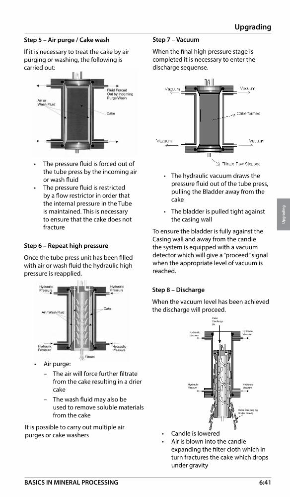
6:41
Upgrading
Upg
radi
ng
BASICS IN MINERAL PROCESSING
Step 7 – Vacuum
When the final high pressure stage is completed it is necessary to enter the discharge sequense.
• The hydraulic vacuum draws the pressure fluid out of the tube press, pulling the Bladder away from the cake
• The bladder is pulled tight against the casing wall
To ensure the bladder is fully against the Casing wall and away from the candle the system is equipped with a vacuum detector which will give a “proceed” signal when the appropriate level of vacuum is reached.
Step 8 – Discharge
When the vacuum level has been achieved the discharge will proceed.
• Candle is lowered• Air is blown into the candle
expanding the filter cloth which in turn fractures the cake which drops under gravity
• The pressure fluid is forced out of the tube press by the incoming air or wash fluid
• The pressure fluid is restricted by a flow restrictor in order that the internal pressure in the Tube is maintained. This is necessary to ensure that the cake does not fracture
Step 5 – Air purge / Cake wash
If it is necessary to treat the cake by air purging or washing, the following is carried out:
Step 6 – Repeat high pressure
Once the tube press unit has been filled with air or wash fluid the hydraulic high pressure is reapplied.
• Air purge:– The air will force further filtrate
from the cake resulting in a drier cake
– The wash fluid may also be used to remove soluble materials from the cake
It is possible to carry out multiple air purges or cake washers
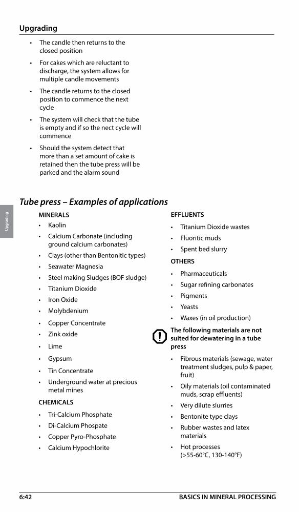
6:42
Upgrading
Upg
radi
ng
BASICS IN MINERAL PROCESSING
Tube press – Examples of applicationsMINERALS• Kaolin
• Calcium Carbonate (including ground calcium carbonates)
• Clays (other than Bentonitic types)
• Seawater Magnesia
• Steel making Sludges (BOF sludge)
• Titanium Dioxide
• Iron Oxide
• Molybdenium
• Copper Concentrate
• Zink oxide
• Lime
• Gypsum
• Tin Concentrate
• Underground water at precious metal mines
CHEMICALS
• Tri-Calcium Phosphate
• Di-Calcium Phospate
• Copper Pyro-Phosphate
• Calcium Hypochlorite
• The candle then returns to the closed position
• For cakes which are reluctant to discharge, the system allows for multiple candle movements
• The candle returns to the closed position to commence the next cycle
• The system will check that the tube is empty and if so the nect cycle will commence
• Should the system detect that more than a set amount of cake is retained then the tube press will be parked and the alarm sound
EFFLUENTS
• Titanium Dioxide wastes
• Fluoritic muds
• Spent bed slurry
OTHERS
• Pharmaceuticals
• Sugar refining carbonates
• Pigments
• Yeasts
• Waxes (in oil production)
The following materials are not suited for dewatering in a tube press
• Fibrous materials (sewage, water treatment sludges, pulp & paper, fruit)
• Oily materials (oil contaminated muds, scrap effluents)
• Very dilute slurries
• Bentonite type clays
• Rubber wastes and latex materials
• Hot processes (>55-60°C, 130-140°F)

6:43
Upgrading
Upg
radi
ng
BASICS IN MINERAL PROCESSING
Tube press – SizesThe tube press 500 series is available mainly in two different sizes.
500 series. Casing diameter 500 mm. Nominal lengths available 1 500 mm and 3000 mm. Maximum pressure 100 bar (1 450 psi).
Model 500 Series 1.5 m 500 Series 3 m
Filtration pressure - max. (bar) 100 100
Length of candle (mm) 1 500 3 000
Candle diameter (mm) 389 389
Filter area (m2) 1.75 3.47
Effective volume (liters) 100 200
Candle weight (kg) 580 1 100
Total weight (kg) 2 000 3 000
Crane height (m) 6.17 9.17
Tube press – SizingThe throughput for a tube press depends on:• Cycle time• Weight of each cake drop (chamber capacity)Typical cycle time without air-purgeLow pressure hydraulics 0 – 5 sec.Slurry fill 10 – 30 sec.Low pressure hydraulics 10 – 30 sec.High pressure hydraulics (100 bar) 60 – 360 sec.(could be less than 60 sec. to more than 10 min.)Vacuum and discharge 45 – 90 sec.
Total cycle time 125 – 515 sec.
Cycle time with one air-purgeLow pressure hydraulics 0 – 5 sec.Slurry fill 10 – 30 sec.Low pressure hydraulics 10 – 30 sec.High pressure hydraulics (100 bar) 30 – 180 sec.Air - purge I:Air injection 30 – 60 sec.High pressure hydraulics (25 bar) 60 – 360 sec.Vacuum and discharge 45 – 90 sec.
Total cycle time 185 – 755 sec.
Tube press – Material of constructionWetted parts – All metallic components of the tube press which come into contact with the process slurry is made from duplex stainless steel.
Casing – The casing and non-wetted parts are generally made from carbon steel.
Bladder – Standard material is natural rubber. Other elastomers can be considered for special process applications.
Filter cloth – Selected against specific process requirements.
See also data sheet 6:61

6:44
Upgrading
Upg
radi
ng
BASICS IN MINERAL PROCESSING
Second and third air-purge could be applied but are very seldom used.
Most effect is obtained with the first air purge, and the throughput for the press is reduced considerably with each air-purge applied.
A cycle incorporating cake wash would be similar to air-cycle above.
Tube press – Cycle times and cake moisture
Typical cycle times and rest cake moisture: time (sec) moisture (%)
Fine coal. without air purge 220 23.0
Fine coal. with air purge 280 15.0
Zinc concentrate. without air purge 174 9.4
Zinc concentrate. with air purge 200 6.2
Zinc concentrate with air purge 273 13.2
Lead concentrate without air purge 297 12.1
Tube press – CapacityThe amount of solids filled into the tube each cycle depends on optimal cake thickness, solids specific gravity, feed slurry density (cake build up) etc.
The capacity per unit (500 series) for some typical applications are given in following table:
Product Slurry feed Cake moisture Output/Tube 3m (% solids w/w) (%) (kg/h dry) (lb/h dry)
Tin concentrate 45 9.0 1 250 2 750
Coal fines 45 15.5 1 200 2 650
Copper fume 35 20.0 450 990
Copper supergene 60 11.5 1 300 2 900
Lead concentrate 60 7.0 2 250 5 000
Zinc concentrate 60 7.5 2 250 5 000
China clay filler 25 16.5 350 770
Iron oxide 55 20.0 1 500 3 300
Acid effluent 15 35.0 375 825
Sulphur effluent 20 35.0 415 910
Mixed sulphides 40 14.0 2 250 5 000
Ex: Dewatering of 9.5 t/h (dry) tin concentrate (well thickened) in tube press.
Capacity per tube = 1250 kg/h (dry)
9500/1250 = 7,6
Select 8 tube presses type 500 !
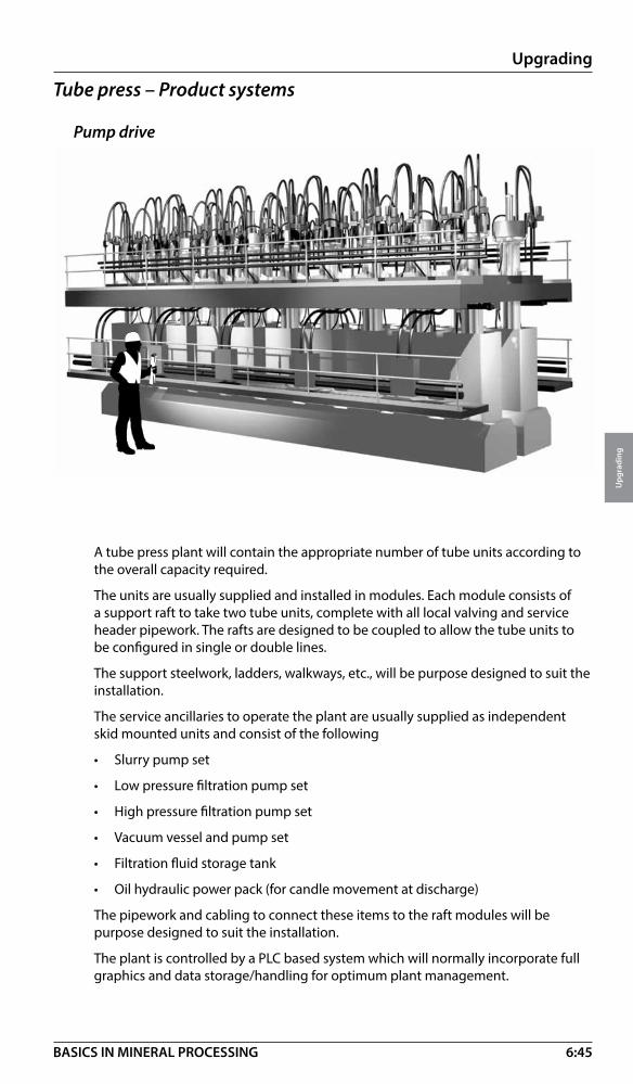
6:45
Upgrading
Upg
radi
ng
BASICS IN MINERAL PROCESSING
Tube press – Product systems
Pump drive
A tube press plant will contain the appropriate number of tube units according to the overall capacity required.
The units are usually supplied and installed in modules. Each module consists of a support raft to take two tube units, complete with all local valving and service header pipework. The rafts are designed to be coupled to allow the tube units to be configured in single or double lines.
The support steelwork, ladders, walkways, etc., will be purpose designed to suit the installation.
The service ancillaries to operate the plant are usually supplied as independent skid mounted units and consist of the following
• Slurry pump set
• Low pressure filtration pump set
• High pressure filtration pump set
• Vacuum vessel and pump set
• Filtration fluid storage tank
• Oil hydraulic power pack (for candle movement at discharge)
The pipework and cabling to connect these items to the raft modules will be purpose designed to suit the installation.
The plant is controlled by a PLC based system which will normally incorporate full graphics and data storage/handling for optimum plant management.

6:46
Upgrading
Upg
radi
ng
BASICS IN MINERAL PROCESSING
For the tube press to operate it requires an infrastructure of ancillary equipment to provide the necessary services. A general pump drive product system is shown below.
These services are:
• Slurry feed• Filtration pressure system• Low pressure• High pressure• Vacuum• Candle jack hydraulics• Oil hydraulic power pack• Compressed air• PLV based control system
Tube press booster systemThe tube press booster is a compact intelligent dewatering system for small scale applications in mineral, chemical and pharmaceutical industries.
“Compact filtration unit” / Booster system
The booster is an individual drive system closely coupled with the tube press.
The installation is compact and combining one motor to generate the mechanical dewatering press force.
The system incorporates fully optimized control of the complete process, including feed back and statistical analysis of each press cycle.
Low Pressure
Pumping System
High Pressure
Pumping System
Hydraulic
Vacuum
System
Service
Water
Reservoir
Service
Water ValveService
Water Valve
Slurry
Feed
Pump
Oil Hydraulic
Power Pack
Screened
Slurry
Feed
Compressed Air
Slurry
Control
Valve
Slurry
Control
Valve

6:47
Upgrading
Upg
radi
ng
BASICS IN MINERAL PROCESSING
Mechanical descriptionThe drive unit incorporates an oil hydraulic power pack and a booster. The oil driven hydraulic power pack provides the driving force, which is converted via the booster unit into a water based pressure medium.
The pressure and dewatering speed is controlled via the control system, which is constantly receiving feedback from sensors and a positional pump. This results in the ability to continuously increase the pressures matching the dewatering curve of the material.
Slurry line
CD air line
Flush water LineService air line
The booster systemSmall to medium installation size installation advantages:
• Low cake moisture
• Excellent liquid/solid separation
• Compact design and is easy to install.
• Fully optimized control
• Useful quality production information and data exchange
• Easy to expand
• Few moving parts
• Increased efficiency by on line process control
• Environmental advantage by high grade of recovery
• Maximum energy exchange
• Closed media circuit
• Low installed power
• Maintenance friendly
• Fully automated
Control systemThe tube press is operated from the operator’s monitor located on the control panel.
The monitor is connected to a PLC that handles the control logics and interlockings.
All process specific data and parameters can be set and adjusted from the monitor in the settings menu.
Cycle time, press weight, etc., are presented on the monitor.
Filtrate dischargeCake discharge
a
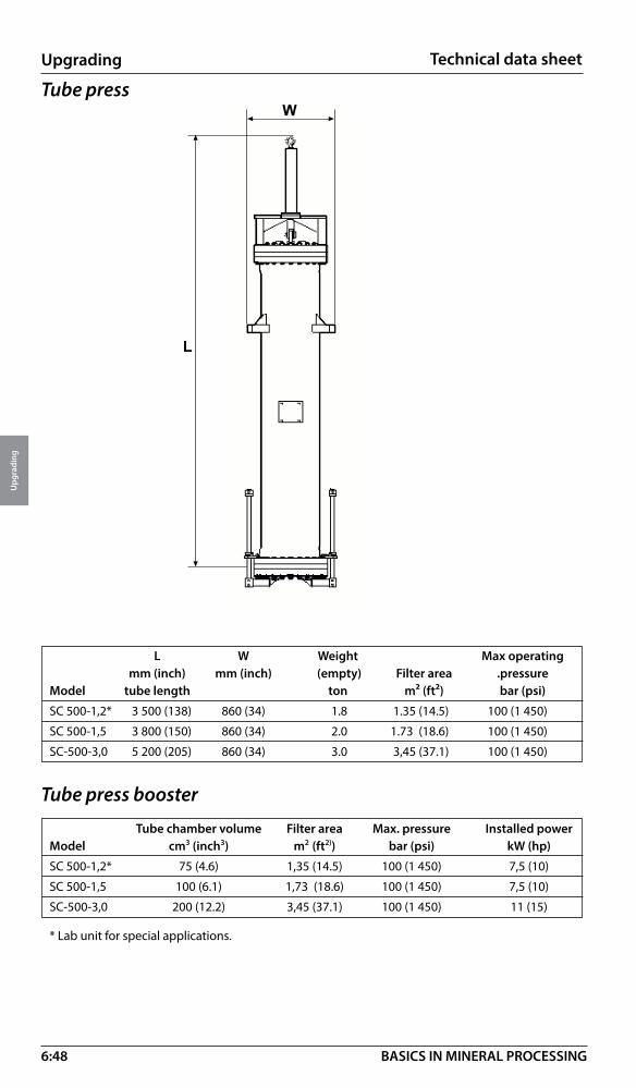
6:48
Upgrading
Upg
radi
ng
BASICS IN MINERAL PROCESSING
Technical data sheet
�
�
L W Weight Max operating mm (inch) mm (inch) (empty) Filter area .pressureModel tube length ton m² (ft²) bar (psi)
SC 500-1,2* 3 500 (138) 860 (34) 1.8 1.35 (14.5) 100 (1 450)
SC 500-1,5 3 800 (150) 860 (34) 2.0 1.73 (18.6) 100 (1 450)
SC-500-3,0 5 200 (205) 860 (34) 3.0 3,45 (37.1) 100 (1 450)
Tube press booster
Tube press
Tube chamber volume Filter area Max. pressure Installed powerModel cm3 (inch3) m2 (ft2)) bar (psi) kW (hp)
SC 500-1,2* 75 (4.6) 1,35 (14.5) 100 (1 450) 7,5 (10)
SC 500-1,5 100 (6.1) 1,73 (18.6) 100 (1 450) 7,5 (10)
SC-500-3,0 200 (12.2) 3,45 (37.1) 100 (1 450) 11 (15)
* Lab unit for special applications.
6:49
Upgrading
Upg
radi
ng
BASICS IN MINERAL PROCESSING
Thermal processing – IntroductionThe level of dewatering that can be achieved through mechanical processes such as VPA’s and tube presses is limited. If further upgrading is required, it must be achieved through thermal processing. Thermal processing is normally classified according to operating temperature.
Thermal low (100 – 200° C)Used for drying – evaporating of liquids from solids - dryingType of equipment• Direct heat rotary dryers • Indirect heat rotary dryers • Steam tube dryers • Indirect heat screw dryers (Holo-Flite®) • Fluid bed dryers
Thermal medium (850 – 950°C)Used for various calcining, clay swelling, limestone burning and foundry sand burn outType of equipment• Direct heat rotary kilns • Indirect heat rotary kilns • Vertical kilns • Fluid bed calciners
Thermal high (1300 –1400°C)Used for vaious calcining operationsType of equipment• Direct heat rotary kiln
• Travelling grate and straight grate induration furnaces
Thermal processing – basicsThermal processing equipment is typically supplied as an integrated system consisting of:• Mechanical dryer or kiln, see above• Feed and product handling equipment• Combustion system (burner, fans, fuel system, etc.)• Offgas handling equipment• Dust collection system (wet or dry)• Cooling system (optional)For thermal processing systems, fuel consumption is one of the largest and most important Operational Expenses. It’s therefore critical that systems are designed in a manner that optimizes the fuel efficiency and the overall heat balance.
As processing temperatures increase from the thermal low range to the thermal high range, there are more opportunities to conserve energy and recover heat. For instance, low temperature dryers are usually not insulated as they typically have insignificant energy losses to atmosphere. However, high temperature kilns are always refractory lined, not only to protect the mechanical parts from the high temperatures but also to reduce the energy losses through radiation to atmosphere. Additionally, the high temperatures in the product and off-gases of a kiln provide greater opportunity for heat recovery systems.

6:50
Upgrading
Upg
radi
ng
BASICS IN MINERAL PROCESSING
Direct heat rotary dryer (Cascade type)• Work horse of the mineral industry • Wide range of internal designs for effective drying from start to end • Special seals for closely controlled atmosphere • Effective combustion and low maintenance burners, safe and reliable • Diameter <0,5-7 m (2 –23 ft), length 6 – 55 m (70 – 180 ft). Feed rates from less
than 1 ton to 1000 tons per hour • Applications in minerals, clay, sand, aggregates, heavy chemicals and fertilizers
Indirect heat rotary dryer (Kiln) • Controlled environment interior excludes products of combustion • Heat transfer by conduction and radiation • Pulse-fired burners available • Facilitates recovery of off-gases and product vapours • Diameter 0,5m – 5,5 m (1.5-18 ft). Length 2.5 m to 28 m (8 – 90 ft).• Applications in hazardous-, ultra fine- and combustible materials. • Regeneration of active carbon, pyrolysis of waste rubber (car types), and plastics.
Exhaust gas
Discharge hood
Riding ring
Material liftersShell
Air sealWet
Feed
Burner
Combustion chamber
Chain drive assembly Support roller
Thrust roller
Product discharge
Spent carbon
Impurities and water vapor to
gas cleaning system
Seals
Exhaust gas to stack
Stationary furnace
Seals
Recoup duct
Feed screw Rotary Kiln Burners Recoup gas tube
Reactivated carbon
Refractory Recoup gas tube
BurnersCombustion chamber of stationary
furnace
Rotary kiln

6:51
Upgrading
Upg
radi
ng
BASICS IN MINERAL PROCESSING
Fluidized bed – key components• Combustion chamber
• Windbox
• Fluoplate
• Expansion chamber
Fluidized bedPrincipalsIn a fluid bed, gases are forced from the windbox through a distributor plate, called the Fluoplate, which delivers the flow evenly to the particle bed and expansion chamber. As the flowrate of the gases is increased to achieve the fluidization velocity, the bed of particles expands and begins to behave very similarly to a fluid with all particles in motion.Product is discharged from the fluid bed as it overflows a weir and spills down the product chute.
Product
����
������������������
�������
������ ����������
���������
Fluoplate
Windbox
Expansion chamber
Combustion chamber
Expansionchamber
Fluoplate
Windbox

6:52
Upgrading
Upg
radi
ng
BASICS IN MINERAL PROCESSING
Fluid bed calciner
Operating temperatures 750 –1200°C.
At such temperatures fuel (gaseous, liquid or solid) is injected directly into the fluid bed.
Heat recovery is done by multistaging the product zones vertically. Calcination gases preheat the feed whilst a cooling zone cools the product and preheats the fluidizing air.
Fluid bed – advantages• A fluid bed behaves like a fluid allowing the use of equipment with no moving
parts.
• The air/particle contact creates optimal heat and mass transfer
• Good agitation and mixing promotes consistent product quality
Fluid bed – applications• Drying with bed temperature 100°C (212°F), (main application area)
• Cooling with bed cooled by water pipes
• Calcining with bed temperatures of 750 – 1200°C (1 382°F – 2 192°F)
• Combustion at operating temperatures of 750 – 900°C (1 382°F – 1652°F), (solid fuels combusted within a sand bed)
Fluid bed dryer• For drying of most granular and powdery materials.• Capacity up to 300 ton/h.
• Particle size minus 6 mm (1/4”), 0.25 – 1.0 mm optimal (60 – 16 mesh)• Size range 6:1 (optimal)
�������
�����������
����
���������
�� �����������
���������
����������
�������
���������
�������������
������� ����
����� �

6:53
Upgrading
Upg
radi
ng
BASICS IN MINERAL PROCESSING
Indirect heat screw dryer (Holo-Flite®)
Operating principleThe principle for the Holo-Flite® dryer is the same as for the indirect heat rotary dryer (described earlier) with the difference that the product to be dried is continuously conveyed by means of the rotating screw flights. By controlling the temperature of the heat transfer medium and the screw speed the drying process can be closely controlled. Heat transfer medium is normally recirculated giving a high thermal efficiency. The design is very compact giving certain advantages in application layouts.
Holo-Flite®– design• Design can take up temperature
variations 0 – 1200° C (30 – 2000° F)
• Construction material carbon steel, and various alloys as required by application for resistance to corrosion and abrasion.
Drive assembly
Timing gears
Feed
Jacketed or non-jacketed end plate
Vapour
Media flow inside screw
Vapour dome or flat covers
Heat transfer media flow to/
from screws
Rotary joints
Discharge
Counter rotating holo-flite screws
Jacketed trough
• Screw diameter 178 – 915 mm (7 – 36”), 1,2 or 4 screws
• Concurrent or counter-current flow of heat transfer medium
• Patented twin pad design
Holo-Flite® – Process systemA typical system includes:
• Single or multiple Holo-Flite® with drives
• Heat transfer medium supply
• Medium heating system (heater with control system, fuel stor- age and expansion tank, heat medium transfer pump, hot medium circulation pumps
• Safety protection (sprinkler and nitrogen)
• Optional PLC controls
• Vapour exhaust fan
• Dust collector (when required)
6:54
Upgrading
Upg
radi
ng
BASICS IN MINERAL PROCESSING
Holo-Flite®– Heat transfer mediumSteam (up to 10 bar) 100 – 200°C 200 – 400°FHot Oil 150 – 350°C 300 – 660°F
Holo-Flite®– applicationsAny material that can be successfully transported through a screw conveyor can also be thermally processed in a Holo-Flite®. The only restriction is with sticky materials that adhere and build up on the surface of the transporting flights. The maximum recommended particle size is 12mm (1/2”).
The Holo-Flite® is an excellent fit for thermally processing materials such as:
• Coal fines• Mineral concentrates (gold, silver, molybdenum, rare earths)• Mineral fines• Carbon black• Iron powder• Other valuable granular and powdery material
Holo-Flite® – sizingHolo-Flite® sizing is a complicated computer exercise that is normally based on laboratory or pilot test work
Some typical drying application figures:
Limestone fines 12 t/h 15°C in 138°C outEquipment used: one 4-screw machine, flight dia 600 mm (24”). Length 7.2m (24ft)
Potassium chloride 9 t/h 0°C in 110°C outEquipment used: one 2-screw machine, flight dia 400 mm (16”). Length 6 m (20 ft)
See also data sheet 6:57.
Cooling technologiesIn most thermal medium and high processing applications the temperatures of discharged products are high. Coolers are used to lower the temperature for product handling equipment and also to recover heat.
Rotary drum coolers Normally there are three basic designs:
• Air swept coolers built similar as a counter flow direct heat rotary dryer, where hot gasses are replaced with ambient air
• Water cooled shell coolers where the drum shell is cooled with water or is submerged in a pool of water.
• Water tube coolers in which heat is transferred from the material to water circulated through tubes inside the cooler.

6:55
Upgrading
Upg
radi
ng
BASICS IN MINERAL PROCESSING
�
�
� �
�
H - overall L - overall W - overall Weight Power (typical) Model mm (inch) mm (inch) mm (inch) empty tonnes kW/hp
S0710-4* 335 (13) 4191 (165) 305 (12) 0,8 0.37/0.5
S0714-4 335 (13) 5410 (213) 305 (12) 1,0 0.37/0.5
D0710-4 335 (13) 4191 (165) 457 (18) 1,2 0.56/0.75
D0714-4 335 (13) 5410 (213) 457 (18) 1,5 0.75/1
S1210-5 565 (22) 4496 (177) 457 (18) 1,3 1.2/1.5
S1218-5 565 (22) 6934 (273) 457 (18) 1,9 2.2/3
D1210-5 565 (22) 4826 (190) 711 (28) 2,3 2.2/3
D1218-5 565 (22) 7264 (286) 711 (28) 2,5 3.7/5
S1614-6 635 (25) 6096 (240) 559 (22) 2,2 2.2/3
S1618-6 635 (25) 7315 (288) 559 (22) 2,5 3.7/5
D1614-6 635 (25) 6096 (240) 864 (34) 3,5 5.5/7.5
D1618-6 635 (25) 7315 (288) 864 (34) 4,5 7.5/10
S2414-6 881 (35) 6299 (248) 762 (30) 3,5 3.7/5
S2424-6 881 (35) 9347 (368) 762 (30) 5,5 5.5/7.5
D2414-6 881 (35) 6706 (264) 1219 (48) 6,5 7.5/10
D2424-6 881 (35) 9754 (384) 1219 (48) 9,5 11/15
Q2418-6 881 (35) 7925 (312) 2159 (85) 15,0 15/20
Q2424-6 881 (35) 9754 (384) 2159 (85) 20,0 22/30
S3022-7 1092 (43) 8941 (352) 965 (38) 7,5 5.5/7.5
S3028-7 1092 (43) 10770 (424) 965 (38) 13,0 7.5/10
D3022-7 1092 (43) 9423 (371) 1600 (63) 16,5 11/15
D3028-7 1092 (43) 11252 (443) 1600 (63) 26,0 15/20
Q3022-7 1092 (43) 9423 (371) 2870 (113) 33,5 22/30
Q3028-7 1092 (43) 11252 (443) 2870 (113) 42,0 30/40
S3622-8 1321 (52) 9017 (355) 1092 (43) 17,0 7.5/10
S3628-8 1321 (52) 10846 (427) 1092 (43) 21,0 11/15
D3622-8 1321 (52) 9525 (375) 1803 (71) 25,5 15/20
D3628-8 1321 (52) 11354 (447) 1803 (71) 32,0 18.5/25
Q3622-8 1321 (52) 9525 (375) 3226 (127) 50,5 30/40
Q3628-8 1321 (52) 11354 (447) 3226 (127) 63,0 37/50
*S 710 - 4, S = single screw, 7 = screw diameter, inch, 10 = screw length 10ft, – 4 = screw pitch 4 inch
D = double screw, Q = Quadruple screw
Holo-Flite® System common sizes
Technical data sheet

6:56
Upgrading
Upg
radi
ng
BASICS IN MINERAL PROCESSING
Fluid bed coolersThe principles of fluid bed can be used also for cooling purposes. In this case the fluid bed is cooled by the fluidizing air and internal water pipes.
Holo-Flite® coolersThe Holo-Flite® is most often used for cooling applications. In these cases, the cooling medium circulating through the screw is water or a water/glycol mixture. Since the design of the screw permits very high feed temperatures, and due to its vertically compact profile, the Holo-Flite® is a perfect fit for boiler bottom ash cooling applications.
Ash cooling – Typical applicationsCirculating fluidized bed boiler
Coolers and heat recoveryRising fuel prices and heightened awareness of environmental issues drive an ever increasing demand for energy efficiency in thermal processing systems.
The most energy efficient systems usually incorporate heat recovery that makes valuable use of the energy released from product cooling.
Flue Gas
Recyclic
Convection PassGas
Hot Cyclone
Solids
Primary Air
Bottom Ash
Ash Handling System
Holo-Flite®
Secondary Air
CombustionCoal
limestone

6:57
Upgrading
Upg
radi
ng
BASICS IN MINERAL PROCESSING
Iron ore pelletizing
What is iron ore pelletizing? Purpose and use of iron ore pelletizingPelletizing is the process through which iron ore fines are transformed into an agglomerated form called “iron ore pellets” suitable for use in an iron-making furnace such as a blast furnace or electric arc furnace. Each iron making furnace has specific iron ore pellet chemistry requirements that govern the design criteria of an iron ore pelletizing plant. In its end product form, a typical iron ore pellet is roughly spherical in shape, measuring from six mm to sixteen mm in diameter and having a crushing strength of over 200 Kg, although some variations in these typical parameters can be specified and targeted in the design process. Under the iron ore pelletizing process, finely ground iron ore is slightly moistened and mixed with a binder. This mixture is continuously fed to a balling disc or drum that forms spheres from the ore fines. The spheres, prior to firing, are called green pellets. Upon discharge from the balling apparatus, the green pellets are separated according to size. Those within the desired size range are transported and fed into an indurating process where they are hardened (indurated) by baking in an oxidizing atmosphere. Off-size pellets are recycled back through the process. The indurating is carried out in a high temperature furnace designed and optimized to achieve the required pellet chemistry. In the final form, the finished pellet product is commonly called “fired pellets” indicating that they have been indurated and hardened. After the pellets are indurated, the fired pellets are transported and screened as necessary to the size required by the customer.The chemistry, physical properties and metallurgical properties of the fired pellets can be adjusted to suit the end use (iron making furnace) by combining the fine ore mixture with various additives prior to firing. The temperature profile of the indurating furnace can also be adjusted to influence the physical and metallurgical properties of the fired pellets over a wide range.Modern plants can be designed to produce in excess of 7 million metric tonnes per annum of fired pellets depending on the design requirements and indurating process employed.
Typical unit operations for iron ore pelletizingAn iron ore pelletizing plant is typically comprised of a series of unit operations in a specific process sequence. Below is a typical schematic for an iron ore pelletizing plant.
The typical pellet plant includes feed preparation where green pellets are produced. These green pellets are then fed to indurating for firing and hardening and producing the “fired pellets”. The fired pellets are then transported to the last unit operation called product handling. Product handling is where the fired pellets may be screened for end user size requirements, or simply transported for storage and load out, or separated and recycled back to the indurating furnace if needed for further processing. Product handling is variable in nature depending on the end user requirements and indurating process employed. Note that in an iron ore pelletizing plant, the indurating process can be carried out by one of two technologies; (1) Grate Kiln technology and (2) Straight Grate technology. Both technologies are viable and proven, and are described in further details below as to when they are used and why.
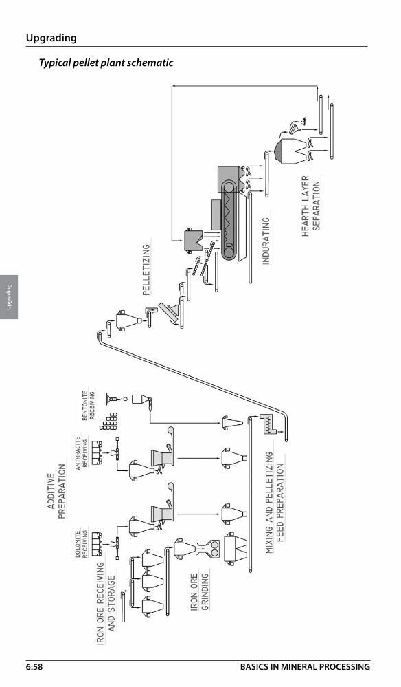
6:58
Upgrading
Upg
radi
ng
BASICS IN MINERAL PROCESSING
Typical pellet plant schematic

6:59
Upgrading
Upg
radi
ng
BASICS IN MINERAL PROCESSING
Feed preparation is the process that produces the green pellet. Feed preparation is the process that combines the iron ore with certain additives to achieve a very specific chemistry for the resulting fired pellet after indurating. Feed preparation for iron ore pellet plants is typically comprised of the following processes.
• Additive preparation – Depending on the criteria specified by the end user of the iron making furnace, additives will need to be combined with iron ore to produce the desired fired pellet chemistry. The quantity and type of additives are determined from laboratory testing. Typical additives for iron ore pelletizing are limestone, dolomite, coal or coke breeze, and bentonite. Bentonite is a binding agent for creation of the green balls. In some plants, alternate organic binders are used instead of bentonite. In order for the additives to be combined with the iron ore, they must meet a specific particle size requirement. If raw additives are delivered to the plant, they must be ground to proper size. This preparation is accomplished by using either air swept vertical roller mills or horizontal ball mills, depending on the capacity needs. Also, in some applications co-grinding of the limestone, dolomite and coal or coke breeze is appropriate. Bentonite must be ground separately due to significant density and hardness differences from the other additives. Depending on the feed preparation process, some of the additive grinding mills may not be required, since the additives can be co-ground with the iron ore grinding mills. Also, if the end user purchases pre-ground additive, additive grinding mills would not be required. These are all variables to be considered in the design.
• Iron ore preparation – Iron ore is supplied to the plant directly from the mine source or supplied from an external source. If the iron ore arrives properly sized and ground for balling (pelletizing), not much iron ore preparation is required. In this instance, the ore will be stored and handled for downstream processing. If not properly sized, the iron ore must be ground to pelletizing size. Iron ore for pelletizing is nominally 80% passing 325 mesh (44 µm), with a Blaine specific surface of between 1600 cm2/g and 1800 cm2/g. If a determination is made, via laboratory testing, that grinding is needed, grinding will be accomplished through the use of either a wet grinding process or a dry grinding process. The selection of the grinding process is determined by the type of ore, availability of water, and downstream process considerations. After grinding, the ore is stored in ground ore storage bins for the downstream processing.
• Mixing – Once the additives and iron ore are prepared, they are transported to the mixing area (building) via belt type conveyors where the materials are mixed and blended into a consistent material with a desired moisture content of around 10%, plus or minus some optimum amount. Mixing takes place in high intensity mixers, of either horizontal or vertical design. After mixing, the mixed ore is transported via conveyors to the balling process for making “green pellets”.
• Balling - The mixed ore is transported to balling feed bins and then to the balling equipment which produces “green pellets” of a spherical shape and variable size distribution. The balling equipment is housed in a building called the “balling building”. In the balling process, the moisture content of the mixed ore and resulting green pellets is optimized by the addition of water via spray nozzles or piping fixtures. The balling process is accomplished by metering a specific quantity of mixed ore from the balling feed bins via conveyors to the balling equipment. Typically, two types of balling equipment can be used, either balling drums or balling discs, each with their own unique operations. The nature and type of balling equipment produces the “green pellets” an
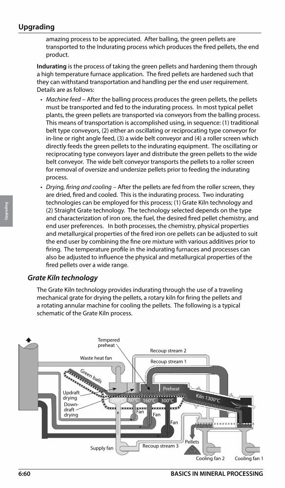
6:60
Upgrading
Upg
radi
ng
BASICS IN MINERAL PROCESSING
amazing process to be appreciated. After balling, the green pellets are transported to the Indurating process which produces the fired pellets, the end product.
Indurating is the process of taking the green pellets and hardening them through a high temperature furnace application. The fired pellets are hardened such that they can withstand transportation and handling per the end user requirement. Details are as follows:
• Machine feed – After the balling process produces the green pellets, the pellets must be transported and fed to the indurating process. In most typical pellet plants, the green pellets are transported via conveyors from the balling process. This means of transportation is accomplished using, in sequence: (1) traditional belt type conveyors, (2) either an oscillating or reciprocating type conveyor for in-line or right angle feed, (3) a wide belt conveyor and (4) a roller screen which directly feeds the green pellets to the indurating equipment. The oscillating or reciprocating type conveyors layer and distribute the green pellets to the wide belt conveyor. The wide belt conveyor transports the pellets to a roller screen for removal of oversize and undersize pellets prior to feeding the indurating process.
• Drying, firing and cooling – After the pellets are fed from the roller screen, they are dried, fired and cooled. This is the indurating process. Two indurating technologies can be employed for this process; (1) Grate Kiln technology and (2) Straight Grate technology. The technology selected depends on the type and characterization of iron ore, the fuel, the desired fired pellet chemistry, and end user preferences. In both processes, the chemistry, physical properties and metallurgical properties of the fired iron ore pellets can be adjusted to suit the end user by combining the fine ore mixture with various additives prior to firing. The temperature profile in the indurating furnaces and processes can also be adjusted to influence the physical and metallurgical properties of the fired pellets over a wide range.
Grate Kiln technologyThe Grate Kiln technology provides indurating through the use of a traveling mechanical grate for drying the pellets, a rotary kiln for firing the pellets and a rotating annular machine for cooling the pellets. The following is a typical schematic of the Grate Kiln process.
Waste heat fanRecoup stream 2
Green balls
Updraftdrying
Recoup stream 1
Down-draftdrying
Temperedpreheat
PreheatKiln 1300 oC200oC 60oC 160oC 300oC
Fan Fan
Fan
Supply fan
Cooling fan 1Cooling fan 2
PelletsRecoup stream 3
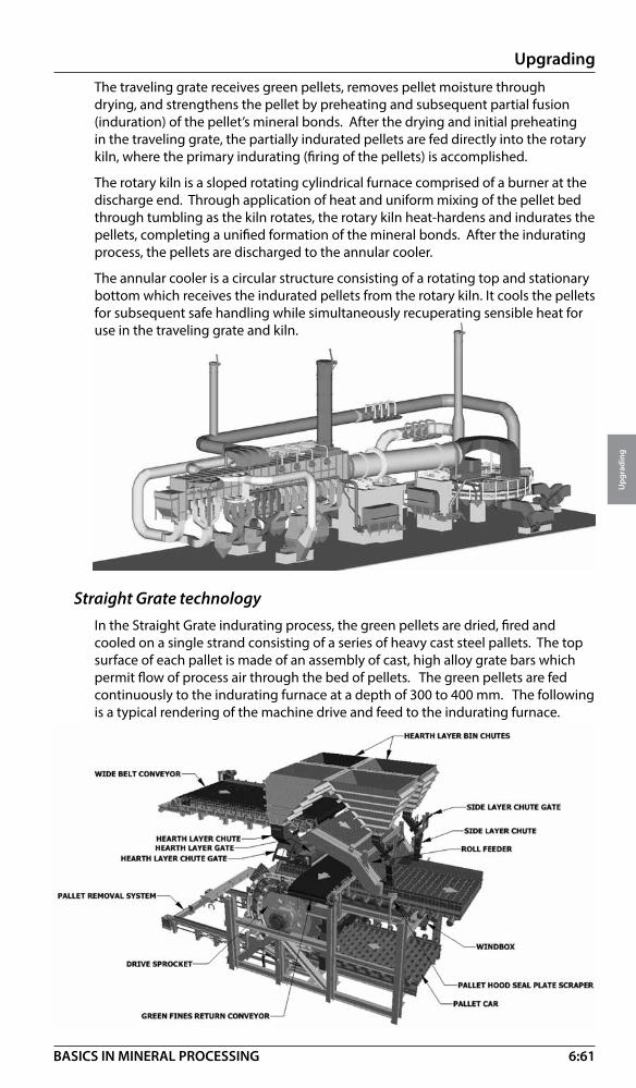
6:61
Upgrading
Upg
radi
ng
BASICS IN MINERAL PROCESSING
Cooling fan 1
The traveling grate receives green pellets, removes pellet moisture through drying, and strengthens the pellet by preheating and subsequent partial fusion (induration) of the pellet’s mineral bonds. After the drying and initial preheating in the traveling grate, the partially indurated pellets are fed directly into the rotary kiln, where the primary indurating (firing of the pellets) is accomplished.
The rotary kiln is a sloped rotating cylindrical furnace comprised of a burner at the discharge end. Through application of heat and uniform mixing of the pellet bed through tumbling as the kiln rotates, the rotary kiln heat-hardens and indurates the pellets, completing a unified formation of the mineral bonds. After the indurating process, the pellets are discharged to the annular cooler.
The annular cooler is a circular structure consisting of a rotating top and stationary bottom which receives the indurated pellets from the rotary kiln. It cools the pellets for subsequent safe handling while simultaneously recuperating sensible heat for use in the traveling grate and kiln.
Straight Grate technologyIn the Straight Grate indurating process, the green pellets are dried, fired and cooled on a single strand consisting of a series of heavy cast steel pallets. The top surface of each pallet is made of an assembly of cast, high alloy grate bars which permit flow of process air through the bed of pellets. The green pellets are fed continuously to the indurating furnace at a depth of 300 to 400 mm. The following is a typical rendering of the machine drive and feed to the indurating furnace.
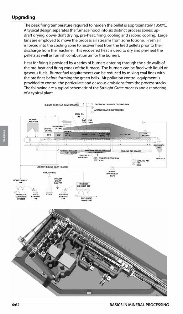
6:62
Upgrading
Upg
radi
ng
BASICS IN MINERAL PROCESSING
The peak firing temperature required to harden the pellet is approximately 1350ºC. A typical design separates the furnace hood into six distinct process zones: up-draft drying, down-draft drying, pre-heat, firing, cooling and second cooling. Large fans are employed to move the process air streams from zone to zone. Fresh air is forced into the cooling zone to recover heat from the fired pellets prior to their discharge from the machine. This recovered heat is used to dry and pre-heat the pellets as well as furnish combustion air for the burners.
Heat for firing is provided by a series of burners entering through the side walls of the pre-heat and firing zones of the furnace. The burners can be fired with liquid or gaseous fuels. Burner fuel requirements can be reduced by mixing coal fines with the ore fines before forming the green balls. Air pollution control equipment is provided to control the particulate and gaseous emissions from the process stacks. The following are a typical schematic of the Straight Grate process and a rendering of a typical plant.

6:63
Upgrading
Upg
radi
ng
BASICS IN MINERAL PROCESSING
After the indurating process, the fired pellets are discharged to the Product Handling system. The Product Handling system typically includes a screening process for either mechanical or gravity separation of pellets by size.
If mechanical separation is used, vibrating screens are typically used to separate pellets into three categories: on-size, undersize and oversize. On-size pellets meet the requirements of the end user. Undersize and oversize pellets are collected for other downstream processes such as sinter feed or are recycled back into the indurating process.
Gravity separation is another commonly used process. Due to the nature of pellets in handling, oversize pellets typically migrate to the outer edges of storage bins or piles. By strategically placing chutes, oversize pellets can be diverted and separated in the process from on-size pellets. While this is a crude methodology, it works well in practice and is the least costly approach. If the client has very specific sizing needs, mechanical separation is the best approach.
Product handing for the Straight Grate process is slightly different than the Grate Kiln process. In the Straight Grate process, a portion of the fired pellets must be separated by size and recirculated back to the front end of the indurating machine, where they are layered on top of the pallets underneath the layer of green pellets. This layer of pellets, called the “hearth layer”, is used to protect the pallets and grate bars from excessive temperature. These hearth layer pellets can be separated either mechanically or via gravity separation as described above.
Major process equipment components of iron ore pellet plant Additive grinding mills – Mills are required for the grinding of limestone, dolomite, coal or coke breeze, and bentonite. Additives are typically ground in either air swept vertical roller mills or horizontal balls mills, depending on the capacity needs. Also, in some applications co-grinding of the limestone, dolomite and coal or coke breeze is appropriate. Bentonite must be ground separately due to significant density and hardness differences with the other additives. Depending on the feed preparation process, some of the additive grinding mills may not be required, since additives may sometimes be co-ground with the iron ore. Also, if the end users purchases pre-ground additives, additive grinding mills would not be required. These are all variables to be considered in the design.
Iron ore rotary dryers - If a dry feed preparation process is designed, rotary dryers prepare the iron ore for feeding to the dry grinding mills by removing nearly 100% of the moisture from the ore.
Iron ore grinding mills – If the iron ore from the supply source is not properly ground to the proper size for pelletizing, ball type grinding mills are used. The ball mills are either dry grinding mills or wet grinding mills depending on the process design. Wet grinding mills produce a slurry for downstream filtration prior to the mixing process. Dry grinding mills produce a final grind directly suitable for feeding to the mixing process.
Filtration equipment – If a wet grinding process is utilized, filtration equipment is supplied to remove water from the iron ore slurry emanating from the wet grinding mills. Depending on the chemical characterization of the iron ore, either Vacuum Filters or Pressure Filters are used. Pressure filters are used commonly when the ore has a high content of alumina (clay) type constituents. Filtration tests are done on the ground ore to determine the applicable filtration equipment.

6:64
Upgrading
Upg
radi
ng
BASICS IN MINERAL PROCESSING
Slurry handling equipment – The wet grinding process requires equipment to pump, store and thicken the slurry prior to filtration. Rubber lined pumps transport the slurry to and from large slurry storage tanks, a concentrate thickener, and eventually the filtration equipment. A concentrate rake type thickener is used in the process to increase the density of the slurry prior to filtration.
Mixer – Mixers are utilized to blend individual pelletizing feed components, iron ore and additives to a homogeneous balling feed. Typically two types of mixers can be used for this process; (1) horizontal rubber lined paddle type mixer, or (2) vertical type bowl mixers with hardened components. Both are equally suitable.
Balling disk or balling drum – A balling disk is a rotating mechanical platform (dish or disk in form) with retention rims to hold and process material. A balling drum is an inclined cylindrical machine (barrel like vessel) that rotates. Both equipment types receive a finely ground mixture of iron ore and other additives and produce uniform spherical pellets through the addition of moisture and the dynamic forces of rotation or circulation.
Balling disc roller screens – Roller type screens are used to separate on-size and off-size green pellets. The off-size materials are recycled, shredded and re-processed through the balling process. On-size pellets are conveyed to the indurating process.
Conveying equipment – Iron ore pellet plants are heavily dependent on belt conveyors for the transfer of bulk materials and pellets from one unit operation to another.
Reciprocating conveyor mechanism – A layout having the balling building at a right angle to the indurating machine will require the use of a reciprocating type conveyor. The discharge pulley at the end of a belt type conveyor moves back and forth, distributing a layer of pellet across the width of the wide belt conveyor. By means of varying the speed of the reciprocating stroke and pulley speed, and the wide belt speed, a relatively even layer of green balls is spread across the wide belt conveyor.Oscillating conveyor – A layout having the balling building in line with the indurating machine will require the use of an oscillating type conveyor. The green ball oscillating feed conveyor receives unfired green ball pellets from the balling disc belt conveyors, and then transfers and distributes the pellets onto the wide belt feed conveyor via an oscillating mechanism. The wide belt conveyor is oriented in line with the oscillating conveyor. By varying the speed of the oscillating head and the wide belt speed, a relatively even layer of green balls is spread across the wide belt
Wide belt conveyor – The wide belt conveyor receives green pellets from the oscillating conveyor or reciprocating conveyor and delivers the pellets to the indurating machine feed roller screen. The wide belt conveyor is a non-standard belt conveyor that, due to its extreme width and belt loading, requires special design considerations and components.
Machine feed roller screens (single deck or double deck) – The green balls are fed onto a roller screen where a series of rotating rollers separate and transport the green pellets to the indurating machine (process). Depending on the capacity of the plant and end user needs, either a single deck roller screen (SDRS) or double deck roller screen (DDRS) is used. The number of rolls is dictated by the capacity of the plant and the final fired pellet sizing requirements. The rollers screens are operated by a variable speed drive which alters the speeds of the rolls and optimizes the screening efficiency.
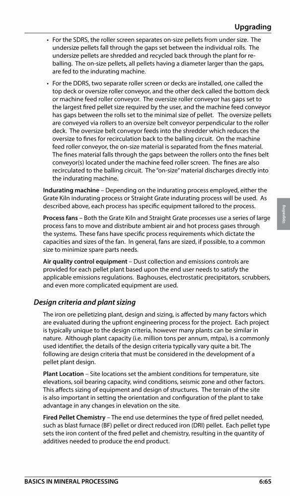
6:65
Upgrading
Upg
radi
ng
BASICS IN MINERAL PROCESSING
• For the SDRS, the roller screen separates on-size pellets from under size. The undersize pellets fall through the gaps set between the individual rolls. The undersize pellets are shredded and recycled back through the plant for re-balling. The on-size pellets, all pellets having a diameter larger than the gaps, are fed to the indurating machine.
• For the DDRS, two separate roller screen or decks are installed, one called the top deck or oversize roller conveyor, and the other deck called the bottom deck or machine feed roller conveyor. The oversize roller conveyor has gaps set to the largest fired pellet size required by the user, and the machine feed conveyor has gaps between the rolls set to the minimal size of pellet. The oversize pellets are conveyed via rollers to an oversize belt conveyor perpendicular to the roller deck. The oversize belt conveyor feeds into the shredder which reduces the oversize to fines for recirculation back to the balling circuit. On the machine feed roller conveyor, the on-size material is separated from the fines material. The fines material falls through the gaps between the rollers onto the fines belt conveyor(s) located under the machine feed roller screen. The fines are also recirculated to the balling circuit. The “on-size” material discharges directly into the indurating machine.
Indurating machine – Depending on the indurating process employed, either the Grate Kiln indurating process or Straight Grate indurating process will be used. As described above, each process has specific equipment tailored to the process.
Process fans – Both the Grate Kiln and Straight Grate processes use a series of large process fans to move and distribute ambient air and hot process gases through the systems. These fans have specific process requirements which dictate the capacities and sizes of the fan. In general, fans are sized, if possible, to a common size to minimize spare parts needs.
Air quality control equipment – Dust collection and emissions controls are provided for each pellet plant based upon the end user needs to satisfy the applicable emissions regulations. Baghouses, electrostatic precipitators, scrubbers, and even more complicated equipment are used.
Design criteria and plant sizingThe iron ore pelletizing plant, design and sizing, is affected by many factors which are evaluated during the upfront engineering process for the project. Each project is typically unique to the design criteria, however many plants can be similar in nature. Although plant capacity (i.e. million tons per annum, mtpa), is a commonly used identifier, the details of the design criteria typically vary quite a bit. The following are design criteria that must be considered in the development of a pellet plant design.
Plant Location – Site locations set the ambient conditions for temperature, site elevations, soil bearing capacity, wind conditions, seismic zone and other factors. This affects sizing of equipment and design of structures. The terrain of the site is also important in setting the orientation and configuration of the plant to take advantage in any changes in elevation on the site.
Fired Pellet Chemistry – The end use determines the type of fired pellet needed, such as blast furnace (BF) pellet or direct reduced iron (DRI) pellet. Each pellet type sets the iron content of the fired pellet and chemistry, resulting in the quantity of additives needed to produce the end product.
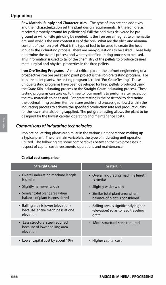
6:66
Upgrading
Upg
radi
ng
BASICS IN MINERAL PROCESSING
Raw Material Supply and Characteristics – The type of iron ore and additives and their characterization set the plant design requirements. Is the iron ore as received, properly ground for pelletizing? Will the additives delivered be pre-ground or will on-site grinding be needed. Is the iron ore a magnetite or hematite ore, and what is the iron content (Fe) of the ore? What are the silica and alumina content of the iron ore? What is the type of fuel to be used to create the heat input to the indurating process. There are many questions to be asked. These help determine the overall process and what type of indurating process to be used. This information is used to tailor the chemistry of the pellets to produce desired metallurgical and physical properties in the fired pellets.
Iron Ore Testing Programs – A most critical part in the upfront engineering of a prospective iron ore pelletizing plant project is the iron ore testing program. For iron ore pellet plants, the testing program is called “Pot Grate Testing”. These unique testing programs have been developed for fired pellets produced using the Grate Kiln indurating process or the Straight Grate indurating process. These testing programs can take up to three to four months to perform after receipt of the raw materials to be tested. Pot grate testing is the basic tool to determine the optimal firing pattern (temperature profile and process gas flows) within the indurating process to achieve the specified production rate and product quality for the raw materials being supplied. The pot grate testing allows the plant to be designed for the lowest capital, operating and maintenance costs.
Comparisons of indurating technologiesIron ore pelletizing plants are similar in the various unit operations making up a typical plant. The one main variable is the type of indurating unit operation utilized. The following are some comparatives between the two processes in respect of capital cost investments, operations and maintenance.
Capital cost comparison
Straight Grate
• Overall indurating machine length is similar
• Slightly narrower width
• Similar total plant area when balance of plant is considered
• Balling area is lower (elevation) because entire machine is at one elevation
• Less structural steel required because of lower balling area elevation
• Lower capital cost by about 10%
• Overall indurating machine length is similar
• Slightly wider width
• Similar total plant area when balance of plant is considered
• Balling area is significantly higher (elevation) so as to feed traveling grate
• More structural steel required
• Higher capital cost
Grate Kiln
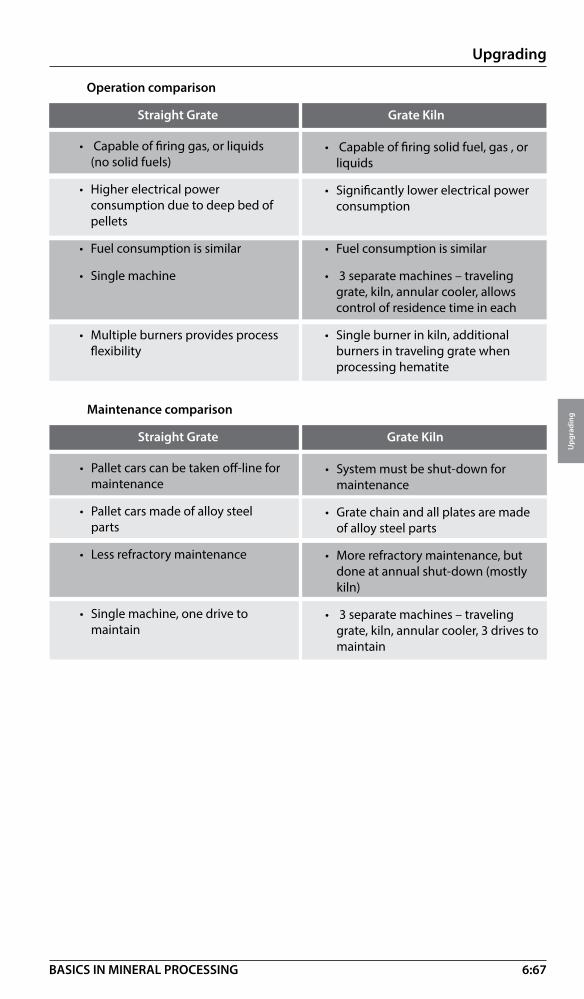
6:67
Upgrading
Upg
radi
ng
BASICS IN MINERAL PROCESSING
Straight Grate
• Capable of firing gas, or liquids (no solid fuels)
• Higher electrical power consumption due to deep bed of pellets
• Fuel consumption is similar
• Single machine
• Multiple burners provides process flexibility
• Capable of firing solid fuel, gas , or liquids
• Significantly lower electrical power consumption
• Fuel consumption is similar
• 3 separate machines – traveling grate, kiln, annular cooler, allows control of residence time in each
• Single burner in kiln, additional burners in traveling grate when processing hematite
Grate Kiln
Operation comparison
Straight Grate
• Pallet cars can be taken off-line for maintenance
• Pallet cars made of alloy steel parts
• Less refractory maintenance
• Single machine, one drive to maintain
• System must be shut-down for maintenance
• Grate chain and all plates are made of alloy steel parts
• More refractory maintenance, but done at annual shut-down (mostly kiln)
• 3 separate machines – traveling grate, kiln, annular cooler, 3 drives to maintain
Grate Kiln
Maintenance comparison
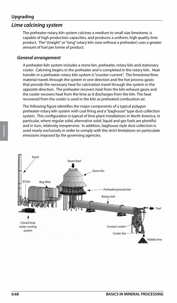
6:68
Upgrading
Upg
radi
ng
BASICS IN MINERAL PROCESSING
Lime calcining systemThe preheater-rotary kiln system calcines a medium to small size limestone, is capable of high production capacities, and produces a uniform, high quality lime product. The “straight” or “long” rotary kiln (one without a preheater) uses a greater amount of fuel per tonne of product.
General arrangementA preheater-kiln system includes a stone bin, preheater, rotary kiln and stationary cooler. Calcining begins in the preheater and is completed in the rotary kiln. Heat transfer in a preheater-rotary kiln system is “counter-current”. The limestone/lime material travels through the system in one direction and the hot process gases that provide the necessary heat for calcination travel through the system in the opposite direction. The preheater recovers heat from the kiln exhaust gases and the cooler recovers heat from the lime as it discharges from the kiln. The heat recovered from the cooler is used in the kiln as preheated combustion air.
The following figure identifies the major components of a typical polygon preheater-rotary kiln system with coal firing and a “baghouse” type dust collection system. This configuration is typical of lime plant installations in North America, in particular, where regular solid, alternative solid, liquid and gas fuels are plentiful and in turn, relatively inexpensive. In addition, baghouse style dust collection is used nearly exclusively in order to comply with the strict limitations on particulate emissions imposed by the governing agencies.
Stack
Bag filter
Stone feed
Stone bin
Preheater/precalciner
ID fan
Closed loop water cooling
system
Rotary kiln
Contact cooler
Fuel
Cooler fan
Pebble lime

6:69
Upgrading
Upg
radi
ng
BASICS IN MINERAL PROCESSING
Process and equipment descriptionLimestone feed is delivered to the un-insulated, carbon steel stone bin, on an intermittent basis, by an appropriate stone preparation and conveying system. It enters the stone bin through an opening at the center of its roof, and is directed to a series of equally spaced discharge points in an annulus at the bottom of the bin. Limestone leaves the stone bin, by gravity, through a set of stone chutes and enters the integral preheater unit, directly below, replacing partially calcined material as it is discharged from the preheater at a controlled rate.
The refractory-lined preheater is made-up of a series of adjoining compartments, or modules, arranged in something of a circular shape (in plan) with a common discharge hopper at the center. Each preheater module receives stone through a four-sided, vertical chute that connects the module to a corresponding discharge opening in the stone bin directly above. These chutes, which are always full of stone during normal operation, create an adequate seal between the process gas stream within the preheater and ambient (at the stone bin inlet). Hot process gases are pulled through the bed of material in the preheater by an induced draft fan (or I.D. fan). The heat content of the gases entering the preheater is such that calcining begins in the preheater. Once through the material bed, having transferred much of the heat to the material, the gases exit the preheater through two exhaust gas manifolds.
Partially calcined material, which has been raised from the near ambient temperature of inside the stone bin to around 760 oC, is pushed from the sloped floor of each module into the center hopper of the preheater by a discharge plunger within the module. Each of these plungers is moved through its stroke cycle by plunger rods connected to a hydraulic cylinder drive mechanism. The alloy steel plunger castings are the only non-refractory lined components found within the preheater.
The partially calcined material passes through the transfer chute and enters the refractory lined rotary kiln, which is installed on a gradual slope away from the transfer chute. Material travels from the upper to lower end of the rotating kiln, while hot process gases are pulled through the kiln in the opposite direction. It is here where the calcining process is completed.
Calcined lime falls from the discharge of the rotating kiln, through discharge grates at the base of the firing hood into the cooler.
As the name implies, it is the firing hood that provides the insertion point for the single burner of the kiln firing system. After passing through the grates at the base of the firing hood, the calcined lime falls into the cooler. Viewed in plan (from the top), the cooler is square and is divided into four cooling compartment, or quadrants. Air is forced into the cooler by the cooler fan. This air cools the lime in counter-current flow through the cooler and then travels up through the cooler grates into the firing hood and kiln, where it serves as preheated secondary combustion air for the firing system

6:70
Upgrading
Upg
radi
ng
BASICS IN MINERAL PROCESSING
System capabilities / flexibilityLimestone FeedSystems has been designed for limestone feed sizes as large as 75 mm, but a more typical maximum top size is 60 mm. Systems have also been designed for feeds as small as 6 mm, but, again, the more typical minimum bottom size is 9 mm. In order to maintain a reasonable pressure drop across the packed bed of material in the preheater, a maximum top-to-bottom size ratio is required. This design feed size ratio if most often a maximum of 4 to 1. However there are preheater-kiln systems in operation today successfully processing stone feed size fractions with top-to-bottom size ratios of 6 or even 7 to 1. Feed size ranges this broad, of course, help to minimize stone cost by maximizing utilization of the quarried stone.
Fuel typesBecause a single burner supplies the process heat to the calcining system, a firing system can easily be designed to handle any of the commonly available forms of fuel–solid, liquid or gaseous. The system can be designed to fire a single type of fuel, or a combination of fuels. There are also designed systems for plant sites around the world that use fuels such as fuels oils of various grades, natural gas and coke oven gas, among others.
Fuel ratesThe greater the rated capacity of a preheater-kiln system, the less fuel it will consume per tonne of lime product. This is simply because there is less equipment surface area available for system heat loss, per tonne of product, at higher system production capacities. The expected nominal fuel rate for an 1100 metric ton per day preheater-kiln system would be in the range of 1000-1150 kcal/kg of lime (4185-4815 kJ/kg), net basis.
Lime product qualityThe combination of the preheater and the rotary kiln working together produces an extremely homogenous lime product of very high quality. In the preheater the finer size particles are calcined more completely than are the coarser particles. In the rotary kiln, because the finer material is trapped in the “kidney” of the rotating bed, somewhat isolated from the hot process gases as it travels through the kiln, the opposite is true. The end result is that by the time the material reaches the discharge end of the rotary kiln all of the material is calcined to the same extent. In addition, because limestone feed to the system is typically no larger than 60 mm, each piece of material can be calcined thoroughly, leaving only small amounts of residual CO2 in the material, when required. The preheater-rotary kiln system is capable of producing limes with a residual CO2 as high as 3.0% and a high reactivity, and as low as 0.01% – basically dead burned.
The preheater-rotary kiln system is also a proven means of producing steel industry grade–low sulfur–lime. Sulfur capture by the material as it travels through the calcining system is a mass transfer phenomenon, which takes place when sulfur in the process gas stream is in intimate contact with the material. Since the preheater-kiln system maintains a relative short packed bed of material (relative to other types of kiln systems) in the preheater, little opportunity is provided for the transfer. In addition, if a fuel is used that has a sufficiently low sulfur content, some of the sulfur entering the system in the stone can be driven off in the firing zone of the rotary kiln. This sulfur can then attach to the very fine material in the process gas stream and, once through the preheater, be collected .
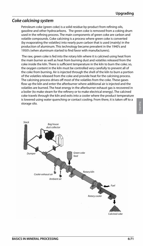
6:71
Upgrading
Upg
radi
ng
BASICS IN MINERAL PROCESSING
StackBag house
dust collector
Green coke feed
Dumper
Cooler exhaust air
Ambient air
Rotary kiln
Rotary cooler
Calcined coke
Fuel
Coke calcining systemPetroleum coke (green coke) is a solid residue by-product from refining oils, gasoline and other hydrocarbons. The green coke is removed from a coking drum used in the refining process. The main components of green coke are carbon and volatile compounds. Coke calcining is a process where green coke is converted (by evaporating the volatiles) into nearly pure carbon that is used (mainly) in the production of aluminum. This technology became prevalent in the 1940’s and 1950’s (when aluminum started to find favor with manufacturers).
The raw, green coke is fed into the rotary kiln where it is calcined using heat from the main burner as well as heat from burning dust and volatiles released from the coke inside the kiln. There is sufficient temperature in the kiln to burn the coke; so, the oxygen content in the kiln must be controlled very carefully to prevent all of the coke from burning. Air is injected through the shell of the kiln to burn a portion of the volatiles released from the coke and provide heat for the calcining process. The calcining process drives off most of the volatiles from the coke. These gases flow up the kiln and enter the afterburner where additional air is injected and the volatiles are burned. The heat energy in the afterburner exhaust gas is recovered in a boiler (to make steam for the refinery or to make electrical energy). The calcined coke travels through the kiln and exits into a cooler where the product temperature is lowered using water quenching or contact cooling. From there, it is taken off to a storage silo.

6:72
Upgrading
Upg
radi
ng
BASICS IN MINERAL PROCESSING
Tire pyrolysisWorldwide, it is estimated that one billion scrap tires are produced every year. Have you ever wondered what happens to all of these scrap tires?
In the US, the majority of tires are used as a supplemental fuel source. The heating value per pound of tires is slightly higher than coal. Cement kilns, waste incinerators and boilers for paper mills are the biggest users (mainly because they can easily handle the leftover metal radials). The second biggest user of scrap tires is the asphalt industry. In the end, however, an estimated 9% of scrap tires (26 million tires per year) end up in a landfill. Worldwide, we know this percentage is much higher, especially in developing countries like China and India. That leaves some 100 million tires ending up in a landfill where they will remain for a long, long time.
To maximize the economy of recycling tires, a process has been developed where all major components of the tire can become revenue streams (money generators) for the recycler. This means making use of the steel, carbon black (major component of the rubber) and the fossil fuel components of the rubber (specifically the oil). These are the big three. Instead of burning the tires, they are roasted at a lower temperature in an atmosphere devoid of oxygen (so that no actual burning occurs). This method of roasting is called pyrolysis, and is used for many different processes. By using pyrolysis, the tire shreds can be broken down into their three basic components (carbon black char, steel radials and oil/gas). Since the three off-coming streams can be captured and sold, the recycling process becomes profitable and not just possible!
The figure below shows the basic tire pyrolysis system...
Indirect rotary kilns
Carbon capture bin
Tire shred feed system

6:73
Upgrading
Upg
radi
ng
BASICS IN MINERAL PROCESSING
Shredded tire chips approximately two inches by four inches are received at the recycling facility. The chips are fed to an indirect rotary kiln using special conveyors. In the indirect kiln, the pyrolysis reaction is carried out. Remember, an indirect kiln adds heat from outside (through the shell) and there is no direct flame inside the kiln. This is done because no oxygen can be present for the pyrolysis reaction to correctly occur. The chips go through three stages inside the kiln. First, the rubber becomes brittle and separates from the steel (we call this the rubber char). In the second stage, the oil and gas are forced from the rubber char and collected. In the last stage, the char is fully processed into a carbon black-like substance and separated from the steel wires. The char is sent through a holo-flite processor (to cool it) and then sent to a bagging system where it is packaged for transport.
The steel is cooled in an air dryer and the steel wires are compacted and shipped to a steel recycler or steel processing furnace. The off-gas from the kiln is pulled through a patented condenser where oil is extracted. This oil is very similar to a diesel fuel. In addition, there is a gas stream of non-condensable oil that can be sent to a boiler and used for generating steam (for heating or power generation).
From a single tire, approximately 1/3 of the mass recovered is steel, 1/3 becomes carbon black and the other 1/3 is oil. Hundreds of hours of continuous testing and processing of thousands of pounds of tire shreds has been conducted to learn the correct method for heating the tires, the best method for handling the shreds, the best method for handling the wires and also the best configuration for the oil condenser. Many technological hurdles have been crossed through this testing (such as preventing pluggage in the condenser, tangling of the chips as they enter the kiln and effectively cooling the rubber char).

7:1
Materials handling
Mat
eria
ls
hand
ling
BASICS IN MINERAL PROCESSING
IntroductionIn the process stages of size reduction, size control, enrichment and upgrading the values of the minerals or rock are brought to their optimum.
We will now look closer into what forms these process stages into a continuous operation.
With materials handling we understand the technologies for moving the process forward with a minimum of disturbances in capacity and flow. These technologies are:
• Loading and unloading • Storing • Feeding • Transportation
For practical reasons we are using the term materials handling for dry processes only.
Of course, the technologies for moving a wet process forward are equally important. We call this slurry handling and the subject will be covered in section 8!
Loading and unloadingIn this section we will only cover loading and unloading conditions related to rail cars and sea vessels (high capacity conditions)
Railcar dumpersRail is the most common inland way of hauling large quantities of raw ore, up- graded minerals and coal etc, and unit trains up to 200 rail cars have to be unloaded during shortest possible time observing safety and environmental requirements.
Railcar dumper – rotary type• Reliable and proven design • Capacities up to 100 cars/h• Single, tandem or triple car dumper configurations• Dust sealed operation • Integrated dust containment system

7:2
Materials handling
Mat
eria
ls
hand
ling
BASICS IN MINERAL PROCESSING
Railcar dumper – “Crescent” design• Low in energy (rotation axis close to gravity centre of loaded cars)• Hopper position close to rail track • Hydraulic car clamping system (closed loop) • Rate of unloading 60 cars/h and line
Rail car dumper - Rotaside® type• Hopper position at the side of rail track gives simplified installation• Proven and simple design • Low in maintenance • Rate of unloading 12 cars/h
Train positionersA train positioner has to have a high utilization capability to enable it to precisely position blocks of 1-10 railcars up to heavy train in excess of 200 railcars using a preset velocity pattern. In duties ranging from 5 to 90 cars unloading per hour there are a number of options for positioners.
System
Side arm system (rack and pinion drive), see picture nest page
Reversible hydraulic indexer system
Wire rope car pullers
Vertical capstan system
Double side arm system (Gemini®)
Unloading duty
Heavy 100 car, or more, trains at high capacity
25 ton pull, 5-15 cars/hour
From 2-12 ton pull at variable speeds
Manual operation - limited pull and distances
For very high unloading rates
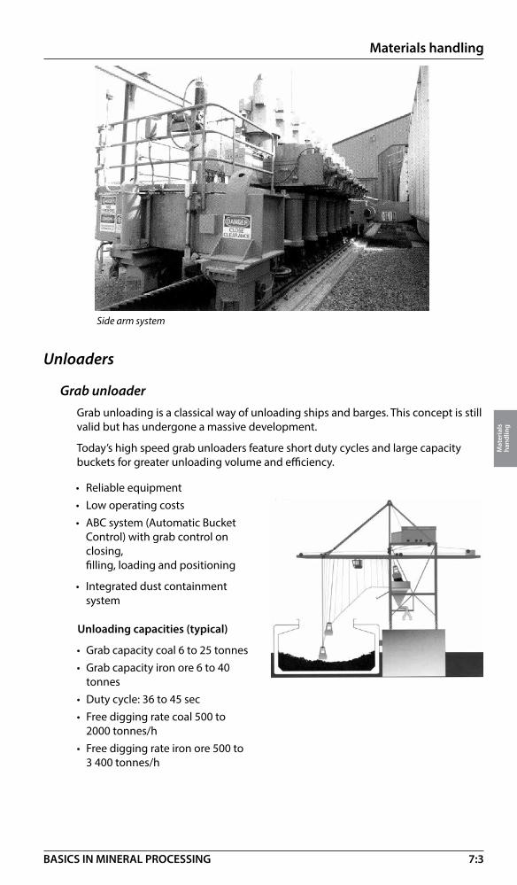
7:3
Materials handling
Mat
eria
ls
hand
ling
BASICS IN MINERAL PROCESSING
Unloaders
Grab unloader Grab unloading is a classical way of unloading ships and barges. This concept is still valid but has undergone a massive development.
Today’s high speed grab unloaders feature short duty cycles and large capacity buckets for greater unloading volume and efficiency.
Side arm system
• Reliable equipment • Low operating costs • ABC system (Automatic Bucket Control) with grab control on
closing, filling, loading and positioning
• Integrated dust containment system
Unloading capacities (typical)
• Grab capacity coal 6 to 25 tonnes• Grab capacity iron ore 6 to 40
tonnes• Duty cycle: 36 to 45 sec• Free digging rate coal 500 to
2000 tonnes/h• Free digging rate iron ore 500 to
3 400 tonnes/h
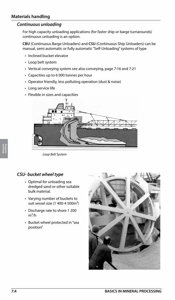
7:4
Materials handling
Mat
eria
ls
hand
ling
BASICS IN MINERAL PROCESSING
Continuous unloadingFor high capacity unloading applications (for faster ship or barge turnarounds) continuous unloading is an option.
CBU (Continuous Barge Unloaders) and CSU (Continuous Ship Unloaders) can be manual, semi automatic or fully automatic “Self-Unloading” systems of type
• Inclined bucket elevator
• Loop belt system
• Vertical conveying system see also conveying, page 7:16 and 7:21
• Capacities up to 6 000 tonnes per hour
• Operator friendly, less polluting operation (dust & noise)
• Long service life
• Flexible in sizes and capacities
Loop Belt System
CSU- bucket wheel type• Optimal for unloading sea
dredged sand or other suitable bulk material.
• Varying number of buckets to suit vessel size (1 400-4 500m³)
• Discharge rate to shore 1 200 m³/h
• Bucket wheel protected in “sea position”

7:5
Materials handling
Mat
eria
ls
hand
ling
BASICS IN MINERAL PROCESSING
Storage bufferingBuffer storage is some time called “the key to processing”, meaning that without a proper storage throughout a continuous rock or mineral process, production up-time will be gone.
1 m 1 dm 1 cm 1 mm 100 micron 10 micron 1 micron
100 micron
Blending storage >24h
Productionstorage >8h
Run of mine
Grinding
Crushing
Storage in operationThe main purpose of storage is to smooth out:
• Different production rates (cont cyclic)
• Shift variations • Interruptions for repair • Size variations • Flow variations • Variations in mineral value
(metal content etc.)
Storage of rock (1)A matter of material flow (retention time)
Storage of ore and minerals (2)A matter of material flow (retention time) and blending
Storage atprimarycrusher
Storageahead offinecrushers
Storage ahead ofsecondary crusher
Storage ahead offinal screens
Storage offinal products
24 hHoistingStorage
(1)
(2)
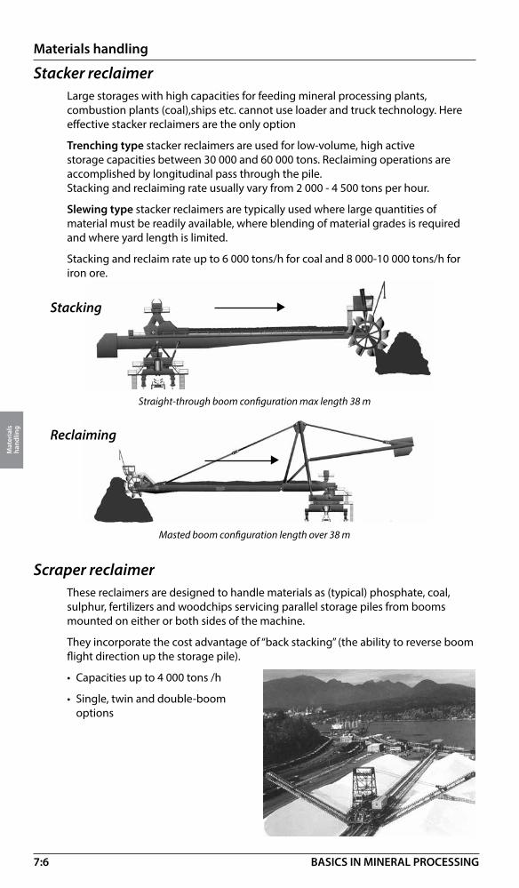
7:6
Materials handling
Mat
eria
ls
hand
ling
BASICS IN MINERAL PROCESSING
Stacker reclaimerLarge storages with high capacities for feeding mineral processing plants, combustion plants (coal),ships etc. cannot use loader and truck technology. Here effective stacker reclaimers are the only option
Trenching type stacker reclaimers are used for low-volume, high active storage capacities between 30 000 and 60 000 tons. Reclaiming operations are accomplished by longitudinal pass through the pile.Stacking and reclaiming rate usually vary from 2 000 - 4 500 tons per hour.
Slewing type stacker reclaimers are typically used where large quantities of material must be readily available, where blending of material grades is required and where yard length is limited.
Stacking and reclaim rate up to 6 000 tons/h for coal and 8 000-10 000 tons/h for iron ore.
Reclaiming
Masted boom configuration length over 38 m
Stacking
Straight-through boom configuration max length 38 m
Scraper reclaimerThese reclaimers are designed to handle materials as (typical) phosphate, coal, sulphur, fertilizers and woodchips servicing parallel storage piles from booms mounted on either or both sides of the machine.
They incorporate the cost advantage of “back stacking” (the ability to reverse boom flight direction up the storage pile).
• Capacities up to 4 000 tons /h
• Single, twin and double-boom options

7:7
Materials handling
Mat
eria
ls
hand
ling
BASICS IN MINERAL PROCESSING
Barrel reclaimer for “Full cross section recovery”The optimal machine reclaiming from a blending pile is the barrel reclaimer.The heart of the machine is a rotating barrel fitted with a large number of buckets.Material collected in the buckets is discharged into an internal conveyor feeding a downstore conveyor running alongside the pile.
• Very robust a reliable design for high capacities · Variable speed for differing reclaim rates
• Automatic operation (optional)

7:8
Materials handling
Mat
eria
ls
hand
ling
BASICS IN MINERAL PROCESSING
Primary feeders (For installation under feed bumper hoppers & rail car dumpers)
Apron
Vibrating
Capacity 300 – 12 000 t/h
Capacity 300 – 1 200 t/h
Capacity above 20 t/h
}VIBRATING (unbalanced motor )max feed size approx. 400 mm
VIBRATING (Electromagnetic )max feed size approx. 150 mm
Tolerant to sticky material
Precise in feeding
Precise in feedingTolerant to sticky material
Capacity above 50 t/h
Capacity 0 - 350 t/h
Not tolerant to sticky material
VIBRATING (eccentric shaft)max feed size approx. 1.0 m }
}}}
FeedingFeeders are necessary whenever we want to deliver a uniform flow of dry or moist fractions of rock or minerals.Generally they are categorized by the size of material to be fed, see below.
Feeding vs Feed sizes
Size 1m 1 dm 1 cm 1 mm 100 micron 10 micron 1 micron
APRONmax feed size approx. 2.0 m
Sensitive against fines – 5 mm precise in feeding
BELTmax feed size approx. 50 mm
8

7:9
Materials handling
Mat
eria
ls
hand
ling
BASICS IN MINERAL PROCESSING
Wobbler feeders
Vibrating (eccentric shaft) Vibrating (unbalance motor)
BeltCapacity 80 – 350 t/h
Capacity 55 – 460 t/h
“In circuit” feeders (For installations under ore stockpiles, bins & crusher dischargers)
See also data sheets 7:10 - 7:14.
Capacity 50 – 3 000 t/hApron
Openings between elliptic bars remain constant
Fines, mud or dirt drop through the openings
Oversize moves forward
Size range• See apron and table feeders
Applications• Wet and sticky for: metallic, industrial and
construction minerals
Pitch (scalping)• Fixed and adjustable
Capacity range• Up to 3 500 t/h (5 sizes)
See data sheet 7:15.
Feeding and scalping - when things get sticky!
Capacity 30 – 600 t/h

7:10
Materials handling
Mat
eria
ls
hand
ling
BASICS IN MINERAL PROCESSING
Technical data sheet
Feeder – Apron
�����������
�
��
���������
Model AF 4 AF 5 AF 8 AF 10 AF 12 AF 14 AF 16 AF 18 Width (pan) Weight* Weight* Weight* Weight* Weight* Weight* Weight* Weight* mm/inch ton/lbs ton/lbs ton/lbs ton/lbs ton/lbs ton lbs ton/lbs ton/lbs
610/24 4.1/9 280
762/30 4.3/9 734 5.1/11 580
914/36 4.6/10 300 5.8/1 306
107/42 4.8/10 840 6.3/14 020
1219/48 5.6/12 610 6.6/14 850 8.6/19 160
1372/54 6.0/13 430 7.1/15 840 9.1/20 440 11.8/26 470
1524/60 6.5/14 480 7.5/16 770 9.9/22 080 12.7/28 340 17.1/38 360
1829/72 7.6/16 930 8.8/19 600 11.5/25 870 13.9/31 080 18.4/41 120 22.7/50 800
2134/84 8.1/18 070 9.8/22 060 12.8/28 630 16.2/36 260 19.8/44 330 25.3/56 780 51.1/11 4400
2438/96 8.8/19 650 11.4/25 450 14.2/31 850 17.5/39 120 21.1/47 210 27.0/60 550 56.1/12 5630
2743/108 9.8/21 860 12.5/27 960 15.1/33 750 18.5/41 480 24.3/54 540 32.0/71 770 62.3/13 9650 66.3/14 6220
3048/120 10.7/24 010 13.4/29 950 16.1/36 100 21.3/47 710 25.6/57 442 32.9/73 730 63.9/14 3240 65.9/14 7660
3353/132 34.6/77 540 66.8/14 9730 68.7/15 3880
*Approx, weight of an Apron feeder, length 3 m (10ft) excl. load, skirts, chutes etc. For each additional feet (or 0.3 m) add 7 % in weight.
Feed size approx, 50% of pan width. Capacity range 50 - 12 000 t/h Model AF 4 AF 5 AF 8 AF 10 AF 12 AF 14 AF 16 AF 18Chain pitch 140 (5.5) 171 (6.8) 202 (8.0) 216 (8.5) 229 (9.0) 260 (10.3) 260 (10.3) 317 (12.5) mm (inch)Main beam Width pan Width pan Width pan Width pan Width pan Width pan Width pan Width pan width mm (inch) +356 (14) +457 (18) +457 (18) +457 (18) +508 (20) +584 (23) +584 (23) +610 (24)Feeder suitable suitable suitable suitable suitable suitable suitable suitable lengthHeight (H) 889 (35) 1 041 (41) 1 268 (50) 1 372 (54) 1 625 (64) 1 753 (69) 1 803 (71) on site mm (inch) demands

7:11
Materials handling
Mat
eria
ls
hand
ling
BASICS IN MINERAL PROCESSING
Technical data sheet
Feeder – Vibration (linear motion)
�
��
Model H L W Weight Capacity Max. size(VMHC)* mm (inch) mm (inch) mm (inch) ton ton/h mm (inch)
48/12 1 300 (51) 5 200 (205) 2 050 (81) 6.8 280 - 400 650 (26)
48/15 1 300 (51) 5 160 (203) 2 350 (93) 10.0 420 - 600 850 (33)
60/10 1 870 (74) 6 800 (268) 1 860 (73) 13.2 250 - 350 500 (20)
60/12 1 870 (74) 6 800 (268) 2 060 (81) 14.0 280 - 400 650 (26)
60/15 1 950 (77) 6 800 (268) 2 380 (94) 15.0 420 - 600 850 (33)
60/18 1 650 (65) 6 550 (258) 2 680 (106) 16.5 550 - 800 1 000 (39)
72/21 2 250 (89) 7 800 (307) 2 980 (117) 21.5 700 - 1200 1 000 (39)
* One, two or three grizzly sections as option depending on size

7:12
Materials handling
Mat
eria
ls
hand
ling
BASICS IN MINERAL PROCESSING
Technical data sheetTechnical data sheet
Model H L W Weight Capacity* (VMO) mm (inch) mm (inch) mm/inch ton ton/h*
15/6.5 - 3014 780 (31) 1 770 (70) 1 260/50 0.5 30 – 160
17.5/8 - 40 830 (33) 2 050 (81) 1 410/56 0.7 40 – 210
20/10 - 40 950 (37) 2 300 (91) 1 670/66 1.1 60 – 320
30/10 - 40 1 000 (39) 3 300 (130) 1 670/66 1.5 60 – 300
30/10 - 45 1 000 (39) 3 300 (130) 1 720/68 1.7 100 – 500
20/12.5 - 45 950 (37) 2 300 (91) 1 030/41 1.3 90 – 550
25/12.5 - 45 1 050 (41) 2 790 (110) 1 970/76 1.8 90 – 550
* Capacity at 8° inclination. feed moist sand 1-7mm (16-3 mesh)
Feeders – Unbalanced motor
�
�
�

7:13
Materials handling
Mat
eria
ls
hand
ling
BASICS IN MINERAL PROCESSING
Model H L W Weight Capacity* (VMO) mm (inch) mm (inch) mm/inch ton ton/h*
10/4.5 1 050 (41) 1 000 (39) 450 (18) 0.64 180
15/4.5 1 050 (41) 1 500 (59) 450 (18) 0.71 180
20/4.5 1 050 (41) 2 000 (78) 450 (18) 0.80 180
10/6 1 200 (47) 1 000 (39) 600 (24) 0.77 250
15/6 1 200 (47) 1 500 (59) 600 (24) 0.89 250
20/6 1 200 (47) 2 000 (78) 600 (24) 0.94 250
10/8 1 200 (47) 1 000 (39) 800 (31) 0.98 350
15/8 1 200 (47( 1 500 (59) 800 (31) 1.10 350
20/8 1 200 (47) 2 000 (78) 800 (31) 1.20 350
* Max feed size 50 mm (2”)
Feeder – Belt
� �
�
Technical data sheet

7:14
Materials handling
Mat
eria
ls
hand
ling
BASICS IN MINERAL PROCESSING
Technical data sheet
� �
�
Feeder – Electromagnetic
Technical data sheet
Model H L W Weight Capacity* (VMm) mm (inch) mm (inch) mm/inch ton ton/h*
6/4-8D 455 (18) 825 (32) 510 (20) 60 (130) 55
11/4-20D 570 (23) 1 260 (50) 540 (20) 115 (255) 60
8/5.6-20D 650 (26) 1 120 (44) 660 (27) 120 (265) 110
8/5.6 50D 765 (30) 1 120 (44) 660 (27) 195 (425) 150
14/5.6 50D 765 (30) 1 630 (64) 780 (30) 280 (615) 140
12/8-50D 835 (33) 1 580 (60) 950 (37) 330 (730) 230
12/8-100D 1 060 (42) 1 600 (63) 950 (37) 440 (975) 270
18/8-100D 1 060 (42) 2 175 (86) 970 (38) 560 (1235) 270
18/8-2x100D 1 430 (56) 2 170 (85) 970 (38) 795 (1750) 310
14/10-100D 1 105 (44) 1 960 (77) 1 210 (48) 580 (1280) 410
14/10-2x100D 1 485 (58) 1 960 (77) 1 180 (46) 815 (1795) 460
22/10-2x100D 1 485 (58) 2 710 (106) 1 210 (48) 1 170 (2580) 390
18/12.5-2x100D 1 430 (56) 2 395 (94) 1 435 (56) 1 150 (2535) 460
* Capacity calculated at bulk weight 1600 kg/m³ (100 ³lb/ft) and size of feed 16-25mm (0.75-1”),
inclination 8°, feeder encapsulated. (Non-encapsulated will increase capacity 10%)

7:15
Materials handling
Mat
eria
ls
hand
ling
BASICS IN MINERAL PROCESSING
�
�
����� �
Feeder – Wobbler
Technical data sheet
Pitch 175 (7”) Model H mm (inch) L mm (inch) W mm (inch) Weight ton Power kW/hp
609 (24)–14* 429 (17) 2 829 (111) 727 (29) 2.0 5.6/7.5
914 (36)–14* 429 (17) 2 829 (111) 1 032 (41) 2.3 7.5/10.0
1219 (48)-18 429 (17) 3 527 (139) 1 337 (53) 3.1 7.5/10.0
1372 (54)-18 429 (17) 3 527 (139) 1 489 (59) 7.5/10.0 * also with 16 same add 349 (14) same add 10% sameand 18 bars for each for each double bar double bar
* 609(24) –14, 609 (24) = width of wobble bars – 14 number of bars.
Max feed size 406 mm (16”)
Pitch 229 (9”) Model H mm (inch) L mm (inch) W mm (inch) Weight ton Power kW/hp
914 (36)-16* 648 (26) 4 178 (165) 1 105 (44) 5 4 11/15
1219 (48)-16* 648 (26) 4 178 (165) 1 410 (56) 6 0 11/15
1372 (54)-16* 648 (26) 4 178 (165) 1 562 (62) 6 7 15/20
1524 (60)-16* 648 (26) 4 178 (165) 1 715 (68) 7 7 15/20
1829 (72)-16* 648 (26) 4 178 (165) 2 019 (80) 8 3 15/20 * also with18. same add 457 (18) same add 10% same 20 and 22 bars for each for each double bar double bar
Max feed size 762 mm (30”)
Pitch 292 (11.5”) Model H mm (inch) L mm (inch) W mm (inch) Weight ton Power kW/hp
914 (36)-16* 648 (26) 5 131 (202) 1 105 (44) 6.6 15/20
1219 (48)-16* 648 (26) 5 131 (202) 1 410 (56) 8.1 15/20
1372 (54)-16* 648 (26) 5 131 (202) 1 562 (62) 8.4 15/20
1524 (60)-16* 648 (26) 5 105 (201) 1 715 (68) 8.6 15/20
1829 (72)-16* 648 (26) 5 105 (201) 2 019 (80) 9.2 15/20
* also with18. same add 584 (23) same add 10% same 20 and 22 bars for each for each double bar double bar
Max feed size 762 mm (30”)
Wobbler feeder also available with 318 mm (12.5”) pitch and 368 mm (14.5”) pitch for feed size up to 1900 mm (75”).

7:16
Materials handling
Mat
eria
ls
hand
ling
BASICS IN MINERAL PROCESSING
Profile belts must be used when lifting angle is exceeding 18° . With a limitation of approx. 30° different profiles of the top cover must be selected to prevent bulk material or unit loads from sliding backward. Otherwise reinforcement and material selection criteria are similar as for flat belts above.
Conveyor beltsAlthough the conveyor structure is important, most of the conveying work falls back on the conveyor belt, exposed to the material. Flat belts are dominating, conveying up to a lifting or lowering angle of approx. 18°. Depending on duty the belts are reinforced with different materials (Polyester/ Polyamide, Aramid and Steel Cords) , protected by top and bottom covers. The polymer material in the belt (mainly rubber) is selected according to appearance of heavy wear, heat, flames, oil etc.
Wear Part
Tonnage and size Distance Inclination
ConveyingIn this section we will focus on mineral mass flow by conveying, by far the dominating method when transporting dry material in a mineral processing operation.
Conveyor – generalConveyors are selected from 4 key parameters:
• Tonnage • Material and size • Inclination • Distance
We also must consider wear in operation and the environment (dust, heat, oil or chemicals etc)
See data sheet 7:20
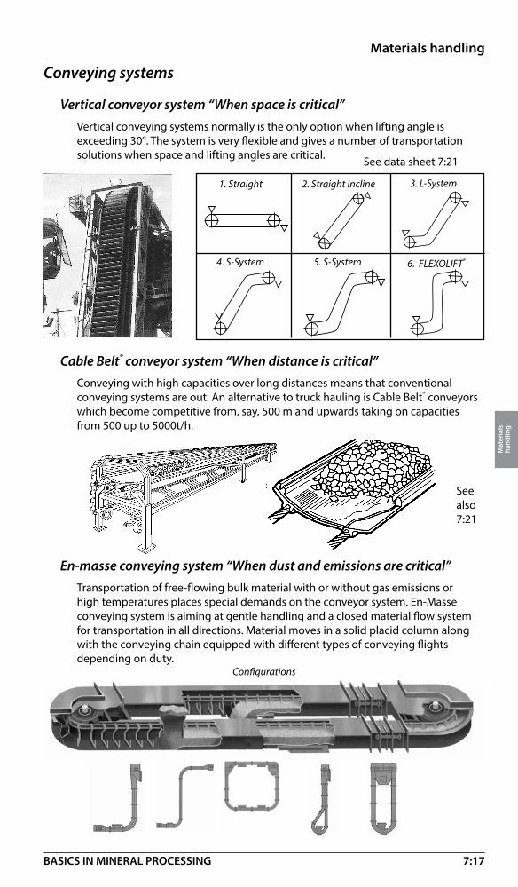
7:17
Materials handling
Mat
eria
ls
hand
ling
BASICS IN MINERAL PROCESSING
Cable Belt® conveyor system “When distance is critical”Conveying with high capacities over long distances means that conventional conveying systems are out. An alternative to truck hauling is Cable Belt® conveyors which become competitive from, say, 500 m and upwards taking on capacities from 500 up to 5000t/h.
En-masse conveying system “When dust and emissions are critical”Transportation of free-flowing bulk material with or without gas emissions or high temperatures places special demands on the conveyor system. En-Masse conveying system is aiming at gentle handling and a closed material flow system for transportation in all directions. Material moves in a solid placid column along with the conveying chain equipped with different types of conveying flights depending on duty.
Configurations
Conveying systems
Vertical conveyor system “When space is critical” Vertical conveying systems normally is the only option when lifting angle is exceeding 30°. The system is very flexible and gives a number of transportation solutions when space and lifting angles are critical.
1. Straight 2. Straight incline 3. L-System
4. S-System 5. S-System 6. FLEXOLIFT®
See data sheet 7:21
See also 7:21

7:18
Materials handling
Mat
eria
ls
hand
ling
BASICS IN MINERAL PROCESSING
Conveyor capacitiesIn order to estimate the capacity and max. recommended inclination of a conventional conveyor the figures below can be of use.
Volume weight and angle of inclinationThe capacity and the inclination of the conveyors depend on the character of the material to be conveyed.
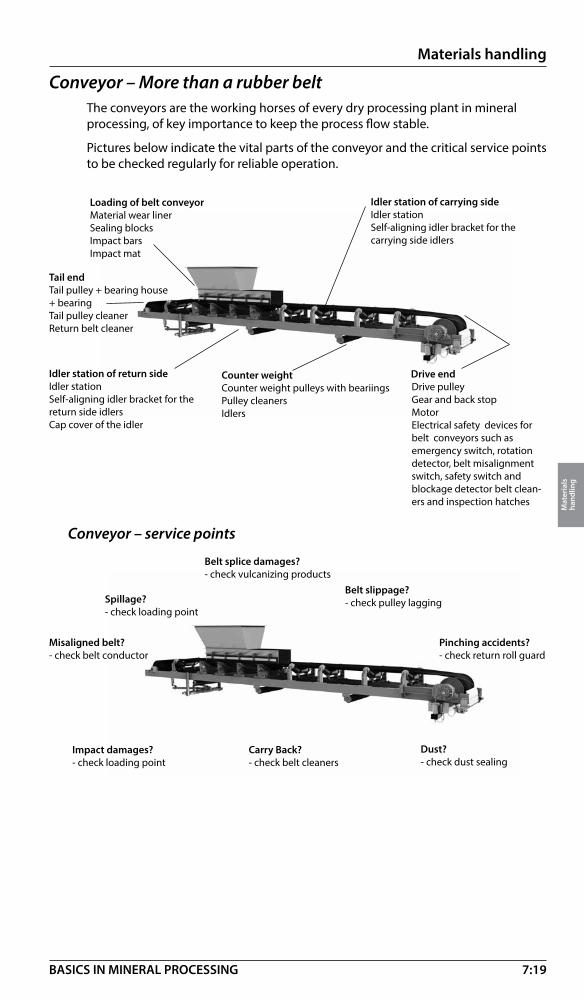
7:19
Materials handling
Mat
eria
ls
hand
ling
BASICS IN MINERAL PROCESSING
Conveyor – More than a rubber beltThe conveyors are the working horses of every dry processing plant in mineral processing, of key importance to keep the process flow stable.
Pictures below indicate the vital parts of the conveyor and the critical service points to be checked regularly for reliable operation.
Drive endDrive pulleyGear and back stopMotorElectrical safety devices for belt conveyors such as emergency switch, rotation detector, belt misalignment switch, safety switch and blockage detector belt clean-ers and inspection hatches
Tail endTail pulley + bearing house + bearingTail pulley cleanerReturn belt cleaner
Loading of belt conveyorMaterial wear linerSealing blocksImpact barsImpact mat
Counter weightCounter weight pulleys with beariingsPulley cleanersIdlers
Idler station of carrying sideIdler stationSelf-aligning idler bracket for the carrying side idlers
Idler station of return sideIdler stationSelf-aligning idler bracket for the return side idlersCap cover of the idler
Conveyor – service points
Dust?- check dust sealing
Belt slippage?- check pulley lagging
Carry Back?- check belt cleaners
Impact damages?- check loading point
Spillage?- check loading point
Misaligned belt?- check belt conductor
Belt splice damages?- check vulcanizing products
Pinching accidents?- check return roll guard

7:20
Materials handling
Mat
eria
ls
hand
ling
BASICS IN MINERAL PROCESSING
Conveyor – Standard belt
�
�
�
��� ���
��
��
��
��
������������
��
��
������
��
��
�������
��
��
�������
Technical data sheet
L m (ft) H m (ft) D mm (ft) Volume m³ (ft³)
6 (20) 2.4 (7.8) 6.5 (21.3) 26 (918)
7 (23) 2.7 (8.9) 7.3 (24.0) 38 (1 342)
8 (26) 3.0 (9.8) 8.2 (26.9) 53 (1 872)
9 (30) 3.3 (10.8) 9.0 (30.0) 71 (2 507)
10 (33) 3.6 (11.8) 9.9 (32.5) 93 (3 284)
12 (40) 4.2 (13.8) 11.6 (38.1) 149 (5 263)
14 (46) 4.8 (15.7) 13.3 (43.6) 225 (7 946)
16 (52) 5.4 (17.7) 15.0 (49.2) 323 (11 407)
18 (60) 6.1 (20.0) 16.7 (54.8) 446 (15 750)
20 (66) 6.7 (22.0) 18.4 (60.4) 596 (21 048)
22 (72) 7.3 (24.0) 20.1 (65.9) 777 (27 440)
24 (80) 7.9 (26.0) 21.8 (71.5) 992 (35 032)
26 (85) 8.5 (28.0) 23.5 (77.1) 1 243 (43 896)
28 (92) 9.2 (30.2) 25.2 (82.7) 1 533 (54 137)
30 (49) 9.8 (32.2) 26.9 (88.3) 1 865 (65 862)
35 (115) 10.8 (35.4) 31.1 (102.0) 2 861 (101 135)
40 (132) 12.9 (42.3) 35.4 (116.1) 4 232 (149 452)
45 (148) 14.4 (47.2) 39.7 (130.2) 5 942 (209 840)
50 (164) 16.0 (52.0) 44.0 (144.0) 8 109 (286 367)
Frame height (H1) – width (B1)
Lenght (belt) Belt width Belt width Belt width Belt width Belt width m/ft 500 mm/20 in 650 mm/26 in 800 mm/32 in 1000 mm/40in 1200 mm/47 in H1 - B1 mm/in H1 – B1 mm/in H1 – B1 mm/in H1 – B1 mm/in H1 – B1/mm/in
6-14/20-46 800/32-890/35 800/32-1040/41 800/32-1240/49 800/32-1440/57 800/32-1690/67
15-24/49-79 800/32-890/35 800/32-1040/41 800/32-1240/49 800/32-1440/57 800/32-1690/67
25-30/82-98 1210/48-950/37 1210/48-1100/43 1210/48-1300/51 1210/48-1500/59 1210/48-1750/69
30-50/82-164 1210/48-950/37 1210/48-1100/43 1210/48-1300/51 1210/48-1500/59 1210/48-1750/69
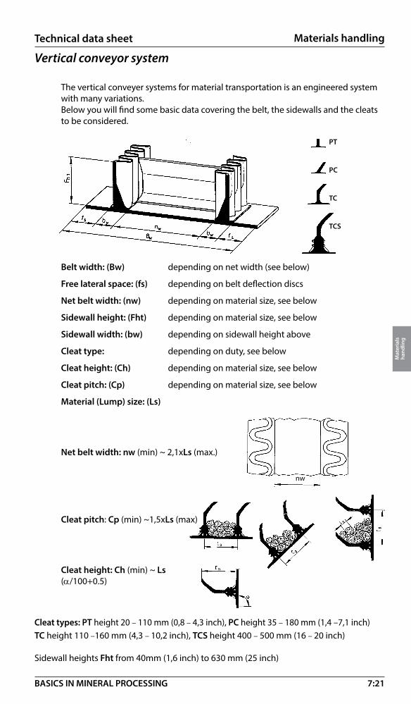
7:21
Materials handling
Mat
eria
ls
hand
ling
BASICS IN MINERAL PROCESSING
Vertical conveyor system
The vertical conveyer systems for material transportation is an engineered system with many variations. Below you will find some basic data covering the belt, the sidewalls and the cleats to be considered.
Belt width: (Bw) depending on net width (see below)
Free lateral space: (fs) depending on belt deflection discs
Net belt width: (nw) depending on material size, see below
Sidewall height: (Fht) depending on material size, see below
Sidewall width: (bw) depending on sidewall height above
Cleat type: depending on duty, see below
Cleat height: (Ch) depending on material size, see below
Cleat pitch: (Cp) depending on material size, see below
Material (Lump) size: (Ls)
Net belt width: nw (min) ~ 2,1xLs (max.)
Cleat pitch: Cp (min) ~1,5xLs (max)
Cleat height: Ch (min) ~ Ls (α/100+0.5)
Cleat types: PT height 20 – 110 mm (0,8 – 4,3 inch), PC height 35 – 180 mm (1,4 –7,1 inch)TC height 110 –160 mm (4,3 – 10,2 inch), TCS height 400 – 500 mm (16 – 20 inch)
Sidewall heights Fht from 40mm (1,6 inch) to 630 mm (25 inch)
nw
Technical data sheet
PT
PC
TC
TCS

8:1
Slurry handling
Slur
ry h
andl
ing
BASICS IN MINERAL PROCESSING
Slurry Handling – Introduction
Hydraulic transportation of solidsIn all wet industrial processes ”hydraulic transportation of solids” involves different stages of solid/liquid mixing, solid/solid separation and solid/liquid separation. These wet industrial processes are further described on page 8:20 - Application Guide.
What type of solids?A solid can be almost anything that is:
Hard Coarse
Heavy Abrasive
Crystalline Sharp
Sticky Flaky
Long fibrous Frothy
You name it – it can be transported hydraulically!
What type of liquids?In most applications the liquid is only the ”carrier”. In 98% of the industrial applications the liquid is water.
Other types of liquids may be chemical solutions like acids and caustics, alcohol, light petroleum liquids (kerosene), etc.
Definition of a slurry• A mixture of solids and liquids is normally referred to as ”slurry”.
• A slurry can be described as a two phase medium (liquid/solid).
• Slurry mixed with air (common in many chemical processes) is described as a three phase fluid medium (liquid/solid/gas).
• Slurries can be settling or non-settling and some terms describing them are:
Mud Paste
Suspensions Slime
Slip Pulp
Dispersions Broth
Silts Slurry
Tailings Sludge
Concentrate Froth
What are the limitations in flow?In theory there are no limits to what can be hydraulically transported. However, particle size, shape, slurry concentration and pipe line designs can restrict flow capabilities.
In practice, the limitations in flow for a slurry pump range from 1 m3/hour (4.4 US gpm) up to 30 000 m3/hour (132,000 US gpm).

8:2
Slurry handling
Slur
ry h
andl
ing
BASICS IN MINERAL PROCESSING
The lower flow limit is determined by the efficiency drop for smaller pumps. The higher flow limit is determined by the dramatic increase of costs for large slurry pumps as compared to the use of multiple pump installations.
Concentrations up to 40 % by volume of solids are typically considered to be the limit for pumping slurries using centrifugal pumps, though higher concentrations have been pumped.
Applications with high concentrations of solids, particularly those with fine particles, must be evaluated carefully, the slurry must be capable of flowing into the impeller eye for it to be pumped.
What are the limitations for solids?The limitation for the solids is the geometrical shape and size and the risk of blocking the passage through a slurry pump.
The maximum practical size of material to be mass transported in a slurry pump is approximately 200 mm (8”).
However, individual lumps of material passing through a large dredge pump can be up to 350 mm (14”) (depending on the dimensions of the wet end passages).
Physical properties of solids to be considered in pump selection:
Maximum size Particle size distribution (d50 and d80)
Shape Hardness
Solid density Concentration (by weight or volume)
Slurry pumps in industry Slurry pumps represent only 5 % of all centrifugal pumps installed in the industry. Yet, understandably, they can represent 80 % of the operating costs.
Consequently, it is very important to select and size slurry pumps to match the application. Metso is constantly developing and implementing product improvements as well as working with end users to provide equipment that increases operating efficiencies.
Basic definitions
Why slurry pumps?By definition slurry pumps are a heavy and robust version of a centrifugal pump, capable of handling tough and abrasive duties. ”A slurry pump should be considered to be a generic term, to distinguish it from other centrifugal pumps mainly intended for clear liquids”.
Slurry pump – name by dutyThe term slurry pump, as stated, covers various types of heavy duty centrifugal pumps used for hydraulic transportation of solids. A more precise terminology is to use the classification of solids handled in the various pump applications.
Slurry and sand pumps cover pumping of mud/clay, silt and sand in the size range of solids up to 2 mm, (9 Mesh)
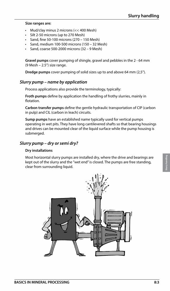
8:3
Slurry handling
Slur
ry h
andl
ing
BASICS IN MINERAL PROCESSING
Size ranges are:
• Mud/clay minus 2 microns (<< 400 Mesh)• Silt 2-50 microns (up to 270 Mesh)• Sand, fine 50-100 microns (270 – 150 Mesh)• Sand, medium 100-500 microns (150 – 32 Mesh)• Sand, coarse 500-2000 microns (32 – 9 Mesh)
Gravel pumps cover pumping of shingle, gravel and pebbles in the 2 - 64 mm (9 Mesh – 2.5”) size range.
Dredge pumps cover pumping of solid sizes up to and above 64 mm (2,5”).
Slurry pump – name by applicationProcess applications also provide the terminology, typically:
Froth pumps define by application the handling of frothy slurries, mainly in flotation.
Carbon transfer pumps define the gentle hydraulic transportation of CIP (carbon in pulp) and CIL (carbon in leach) circuits.
Sump pumps have an established name typically used for vertical pumps operating in wet pits. They have long cantilevered shafts so that bearing housings and drives can be mounted clear of the liquid surface while the pump housing is submerged.
Slurry pump – dry or semi dry? Dry installations
Most horizontal slurry pumps are installed dry, where the drive and bearings are kept out of the slurry and the ”wet end” is closed. The pumps are free standing, clear from surrounding liquid.

8:4
Slurry handling
Slur
ry h
andl
ing
BASICS IN MINERAL PROCESSING
The vertical tank pump has an open sump with the pump casing mounted directly to the underside of the tank. The cantilever impeller shaft, with its bearing housing and drive mounted on the tank top, rotates the impeller inside the pump casing. The slurry is fed from the tank into the “wet end” around the shaft and is discharged horizontally from the outlet. There are no shaft seals or submerged bearings in the design.
Semi dry installations
A special arrangement can be used for dredging applications, where horizontal pumps are used with the ”wet end” (and submerged bearings) flooded. This calls for special sealing arrangements for the bearings.
The sump pump has a flooded “wet end” installed at the end of a cantilever shaft (no submerged bearings) and a dry drive.

8:5
Slurry handling
Slur
ry h
andl
ing
BASICS IN MINERAL PROCESSING
Slurry pumps and wear conditionsTo ensure good service performance under a variety of working conditions and applications several factors must be considered when selecting pumps.
A primary factor is to identify the duty according to its wear service class, using the guidelines given in Hydraulic Institute Standard ANSI/HI 12.1-12.6 “Rotodynamic (centrifugal) slurry pumps”
The HI Standard recommends operating limits for these service classes. These combined with Metso’s pump designs and appropriate material selections will result in optimum wear life.
Metso’s PumpDim sizing program, in conjunction with the HI Standard, is a valuable user friendly resource for selecting pumps for specific applications.
Type of pumpsPumps can be classified by type. This chart gives an overview of major types and the category in which Metso slurry pumps belong.
* Ref: Hydraulic Institute ANSI/HI 12.1-12.6 definitions
Wear service class Slurry class Metso equivalent duty class
1 Light Mildly abrasive2 Medium Abrasive3 Heavy Highly abrasive4 Very heavy Extremely abrasive

8:6
Slurry handling
Slur
ry h
andl
ing
BASICS IN MINERAL PROCESSING
Technical descriptionGeneral
If you look at a breakdown of the relative operating costs for a ”normal” slurry pump installation you will find the factors that guide our design of slurry pumps.
These are our contributions to good operation and economy using Metso Slurry Pumps as described in this section. Visit www.metso.com/pumps
Nomenclature
Series Description - Horizontal pumps
MDM Mill Discharge Pump with Metal PartsMDR Mill Discharge Pump with Rubber PartsXM EXtra Heavy Duty Slurry Pump with Metal Wear PartsXR EXtra Heavy Duty Slurry Pump with Rubber Wear PartsXG EXtra Heavy Duty Gravel PumpHM Heavy Duty Slurry Pump with Metal Wear PartsHR Heavy Duty Slurry Pump with Rubber Wear PartsHG Heavy Duty Gravel PumpHH/HMP High Head/ Pressure Pump with Metal Wear partsHP Heavy Duty High Pressure PumpHT Heavy Duty Tunneling PumpMM Mining Duty Slurry Pump with Metal PartsMR Mining Duty Slurry Pump with Rubber PartsMA MAtrix PumpThomas Dredge PumpMarathon Dredge PumpVASA HD Heavy Duty – Sala design with Metal or Rubber wear parts
Series Description - Vertical pumps
VF Vertical Slurry Pump – Froth type with metal or rubber partsVS Vertical Slurry Pump – Sump type with metal or rubber partsVT Vertical Slurry Pump – Tank type with metal or rubber partsVSHG Vertical Slurry Pump – Sump type, Heavy Duty Gravel wet-endVSHM Vertical Slurry Pump – Sump type, Heavy Duty with Metal partsVSHR Vertical Slurry Pump – Sump type, Heavy Duty with Rubber partsVSMM Vertical Slurry Pump – Sump type, Mining Duty with Metal parts
• High efficiency and minimised solids effect on efficiency drop giving lower power consumption
• New wear materials, both elastomers and metal, of good design giving long life for wear parts
• Service features in the design giving short shut down cycles and low maintenance costs
• Modern sealing designs giving low down time and costs for shaft sealing

8:7
Slurry handling
Slur
ry h
andl
ing
BASICS IN MINERAL PROCESSING
Metso slurry pump series and sizesPump size – inlet flange
Inlet size (mm) (inch)
502
753
1004
1506
2008
25010
30012
350 14
40016
45018
50020
55022
60024
65026
70028
80032
Metso MD seriesMDM
MDR
Orion seriesMM
MM - WFR
MR
HM
HM - WFR
HR
HH
HG
HG - WFR
HP
HT
Thomas seriesMM
MR
XM
XR
Thomas Dredge
Marathon Dredge
MA - MatrixSala seriesVSMM
VSMM - WFR
VSHM
VSHM - WFR
VSHR
VSHG
VSHG - WFR
Outlet size (mm) (inch)
251
401,5
502
808
1004
1506
2008
25010
30012
35014
Sala seriesVS
VT
VF
VASA HD
Pump size – outlet flange

8:8
Slurry handling
Slur
ry h
andl
ing
BASICS IN MINERAL PROCESSING
FRAME 1200
HM50 HR50HM75 HR75MM100 MR100 *)HP75 HT100
HM200HR200MM250MR250 *)HP200
FRAME 300
FRAME 400
FRAME 600
HM100 HR100MM150 MR150 *)HG100 HP100 HT150
FRAME 250
FRAME 300
FRAME 500
FRAME 600
FRAME 400
HM250HR250MM300MM350MR300HG200 HG250HP250HH200HMP150 *)HMPT150 *)
HM300HR300MM400MR350XG250XR300MDM250MDR250MDR300
FRAME 750
MDM300MDR350XM350XR350MM500
FRAME 900
FRAME 1000
MDM350MR500XM400XR400XG350
FRAME 900
MDM400MDR400MDM450MDR450XM500
FRAME 1400FRAME 1400
MDM500MDR500MDM550MDR550XM600XM700
FRAME 750
FRAME 500
FRAME 1000
50
0
FRAME 250
HM150 HR150MM200 MR200 *)HG150 HP150HMPT100 *)
Metso horizontal slurry pump wet-end modular configurations
Frame 900
*) Refer to Metso application engineering
Frame 250
Frame 300
Frame 400
Frame 500
Frame 600
Frame 750
Frame 1400
Frame 1200
Frame 1000

8:9
Slurry handling
Slur
ry h
andl
ing
BASICS IN MINERAL PROCESSING
Metso vertical slurry pump wet-end modular configurations
L120 - 180 VSHM50VSHR50VSHM75VSHR75VSHM100VSHR100 VSMM100VSMM150
VSHM, VSHR, VSMM
L120 - 180VSHM150VSHR150VSHM200VSHR200VSMM200VSMM250
VSHM250 L120-180VSHR250 L120-180VSMM300 L120-180VSMM350 L150-180
Frame size
VS250 L150-180
VS RANGE
VS25 L80VS50 L80
VS25 L120-180VS80 L80VS100 L80
VS50 L120-180 VS80 L120-180VS100 L120-180VS150 L120
VS150 L150-180VS200 L120-180
VT RANGE
VT40
VT50
VT80VT100
VT150
VT200VT250
VF RANGE
VF50
VF80
VF100VF150
VF200VF250
VF350
VA
VB
VC
VD
VE
VF
VG
VSHM, VSHR, VSMM VS RANGE VT RANGE VF RANGE
VA
VB
VC
VD
VE
VF
VG

8:10
Slurry handling
Slur
ry h
andl
ing
BASICS IN MINERAL PROCESSING
Slurry pump range MD
Mill Discharge slurry pumps MDM and MDRSpecifically designed from its inception for mill circuit applications, the Metso MD series of mill discharge MDM hard metal and MDR rubber lined slurry pumps offer sustained performance with maximum time between mill shutdowns.Hydraulic design is consistent across the entire range and by limiting the inlet velocity at design BEP impact damage from coarse heavy solids is kept to an absolute minimum.Large diameter high aspect ratio impellers provide for excellent hydraulic efficiency with minimum turbulence at minimum rotational speed, thereby reducing the rate of wear.Reduced impeller overhang restricts shaft deflection across a wide range of flows, and in so doing maximizes shaft seal and radial bearing life.Suction side recirculation is restricted by an adjustable inlet liner/wear plate. When used in conjunction with the axially adjustable bearing cartridge, the design provides for ‘double adjustment’ ensuring that both suction side and gland side impeller clearances can be set and reset at a minimum.
PUMP DESIGNATIONMDM350MDR350
Pump range Inlet size (mm)
Summary of design features
• High sustained efficiency• Even hydraulic wear• Longer operating life• Oversized robust steel shaft• Extra thick casings and liners at known points of wear• Back pull-out option for ease of maintenance
• Self-contained oil or grease lubricated bearing cartridge assembly with noncontact labyrinth seals for maintenance free operation
• Bearing housing arranged to accept temperature and vibration sensors• Split stuffing box gland and gland guard• Various shaft seal options including Metso EnviroSetTM
• Modular design with good interchangeability of parts• Loose steel connection

8:11
Slurry handling
Slur
ry h
andl
ing
BASICS IN MINERAL PROCESSING
Slurry pump range XM
The Thomas series of extra heavy duty hard metal slurry pumpsThe XM (hard metal), Extra Heavy Duty slurry pump range is designed for the most arduous pumping applications. The rugged “wet end” is designed with extra thick metal sections at known points of wear and the high aspect ratio impeller ensures excellent performance with long wear life.
PUMP DESIGNATIONXM350
Pump Range Inlet size (mm)
Summary of design features
• Modular design technology
• Robust construction designed for highly abrasive, maximum duty
• Thick volute casings and heavy duty solids handling impellers, with high aspect ratio, and carefully matched, high efficiency, hydraulics for even wear
• Materials used are the very best available, providing both excellent wear properties and corrosion resistance
• Self contained bearing cartridge assembly with oversized shaft and grease/oil lubricated anti-friction bearings
• Various shaft seal options
• Ease of maintenance
• Maintenance slide base option

8:12
Slurry handling
Slur
ry h
andl
ing
BASICS IN MINERAL PROCESSING
Dredge pumps
Thomas series of “Simplicity” dredge pumpsThe Thomas “Simplicity” dredge pump is engineered for your specific operation. Years of operation and many design improvements have resulted in a pump which will give you lowest operating cost of any pump in the industry when handling abrasive materials.
The rugged wet-end parts are designed to feature extra heavy metal sections at points of extreme wear – the extra weight pays off in performance and low maintenance cost.
No other dredge pump manufacturer offers the wide range of wearresistant alloys as provided by Metso. Matching the correct alloy to your specific application will give you the best performance and lowest cost.
Summary of design features• Optional rotation – Right or left hand rotation
• Optional discharge positions
• Suction adapter with clean out
• Three and four vane impellers available
• Amor-lok seal on the side liners for metal to metal fit
• Knock out ring for easy impeller removal
• Wide range of alloys for pump wear parts
• Over size bearings and shaft for longer life
• Cantilevered design
– Less shaft deflection – Better packing and bearing life – 360° crescent support – No case feet require

8:13
Slurry handling
Slur
ry h
andl
ing
BASICS IN MINERAL PROCESSING
Slurry pump range VASA HD and XR
The Sala and Thomas series of extra heavy duty rubber lined slurry pumpsThe VASA HD and XR (rubber lined), Extra Heavy Duty slurry pump range is designed for the most arduous pumping applications. The rugged “wear end” is designed with extra thick rubber sections at known points of wear and the high aspect ratio metal impeller, also available in rubber, ensures excellent performance with long wear life.
PUMP DESIGNATIONXR350
Pump Range Inlet Size (mm)
Summary of design features• Modular design technology
• Robust construction, with ”back pull-out” feature, designed for highly abrasive, maximum duty and aggressive environments
• Thick volute casing liners and heavy duty solids handling impellers with high aspect ratio, and carefully matched, high efficiency, hydraulics for even wear
• Materials used are the very best available, providing both excellent wear properties and corrosion resistance.
• Self-contained bearing cartridge assembly with oversized shaft and grease lubricated anti-friction bearings
• Various shaft seal options
• Maintenance slide base option
• Ease of maintenance

8:14
Slurry handling
Slur
ry h
andl
ing
BASICS IN MINERAL PROCESSING
Slurry pump range HR and HM
The Orion series of heavy duty rubber lined and hard metal slurry pumpsThe HR (rubber lined) and HM (hard metal), Heavy Duty slurry pump ranges are designed for the toughest pumping
applications. The excellent hydraulic design, with extra thick sections at known points of wear and the high aspect ratio impeller ensure excellent performance with long wear life.
HR wet end single adjust, HM wet end double adjust
PUMP DESIGNATIONHR or HM100
Pump range: HR Rubber Inlet size (mm)Pump range: HM Metal
Summary of design features• Modular design technology and back pull-out feature
• Robust construction
• Thick volute casing/liner and solids handling, large diameter, impeller with carefully matched, high efficiency, hydraulics for even wear
• Double adjustment for sustained efficiency
• Materials used are the very best available, providing both excellent wear properties and corrosion resistance
• Self-contained bearing cartridge assembly with oversized pump shaft and anti-friction bearings
• Various shaft seal options
• Ease of maintenance
• Maintenance slide base option

8:15
Slurry handling
Slur
ry h
andl
ing
BASICS IN MINERAL PROCESSING
MM wet end single adjust, MR wet end double adjust
Slurry pump range MR and MM
The Orion series of mining duty rubber lined and hard metal slurry pumpsThe MR (rubber lined) and MM (hard metal) mining duty, slurry pump ranges are designed to provide an economical solution to all slurry pump applications. Excellent hydraulic designs maximise efficiency throughout the life of the pump and selection of wear part materials from the extensive Metso ranges of metals and elastomers ensure long wear life.
PUMP DESIGNATIONMR or MM100
Pump range: MR Rubber Inlet size (mm)Pump range: MM Metal
Summary of design features• Modular design technology and back pull-out feature
• Robust construction
• Solids handling, medium diameter impeller with carefully matched, high efficiency, hydraulics for even wear
• Double adjustment for sustained efficiency
• Materials used are the very best available, providing both excellent wear properties and corrosion resistance
• Self contained bearing cartridge assembly with oversized pump shaft and grease lubricated taper roller bearings
• Various shaft seal options
• Ease of maintenance
• Maintenance slide base option

8:16
Slurry handling
Slur
ry h
andl
ing
BASICS IN MINERAL PROCESSING
Slurry pump range VT
The Sala series of vertical tank pumpsMetso´s tank pumps are designed for abrasive slurry service and feature simple maintenance and robust design.
PUMP DESIGNATIONVT100
Pump rangeDischarge size (mm)
Summary of design features• Pump, tank and motor in one integrated unit for flexible layout and simple
installation
• Open sump and vertical inlet prevents air blocking and gives a smooth operation
• Oversize bearings, for added life and minimum maintenance. Double protection sealing arrangement against penetration of slurry.
• Cantilever shaft with no submerged bearings or seals. Shaft made of alloy steel, for superior strength and toughness
• Easily replaced wear parts and metal/rubber interchangeability

8:17
Slurry handling
Slur
ry h
andl
ing
BASICS IN MINERAL PROCESSING
Slurry pump range VF
The Sala series of vertical froth pumpsMetso’s froth pumps are designed to increase the pumpability of frothy suspensions. The principal of operation is similar to that of hydrocyclone separation.
Air is separated from the slurry in a vortex created by the impeller rotation and the tangential inlet to the pump’s conical sump. This results in a more efficient pumping at higher capacities and a smooth operation free from fluctuations.
PUMP DESIGNATIONVF100
Pump range Outlet size (mm)
Summary of design features• Pump, conical tank and motor in one integrated unit for flexible layout and
simple installation
• Vertical inlet prevents air blocking
• Oversize bearings, for added life and minimum maintenance. Double protection sealing arrangement against penetration of slurry
• Cantilever shaft and made of alloy steel, for superior strength and toughness, with no submerged bearings or seals
• Easily replaced wear parts and metal/rubber interchangeability

8:18
Slurry handling
Slur
ry h
andl
ing
BASICS IN MINERAL PROCESSING
Slurry pump range VS
The Sala series of vertical sump pumpsMetso sump pumps are designed specifically for abrasive slurries and feature robust design with ease of maintenance.
The VS sump pump range is one of the strongest, toughest and reliable high volume ranges available on the market. It is for this reason that the range is preferred throughout the world by most heavy industries.
PUMP DESIGNATIONVS100 L120 O4S
Pump range Casing and agitation type optionOutlet size (mm) Outlet size (mm)
Summary of design features• Simple installation
• Cantilever design without submerged bearings or shaft seal
• Bearing assembly with double protection sealing arrangement to prevent ingress of slurry
• Materials used are the very best available, providing both excellent wear properties and corrosion resistance
• Wear parts are available in a variety of different materials with full interchangeability
• Range of impeller options

8:19
Slurry handling
Slur
ry h
andl
ing
BASICS IN MINERAL PROCESSING
Slurry pump range VSHM, VSHR and VSMM
The Sala series of vertical sump pumpsThe VSH and VSM pumps are a new combination of our classic VS sump pumps and our Orion series horizontal pump wet ends. This provides a major advantage to the customer: the same wet end parts are used for both horizontal slurry pumps and sump pumps, thus reducing parts inventory and simplifying maintenance. It does also make it possible to generate a higher TDH, pump head.
PUMP DESIGNATIONVSHM150 L120 C5
5 vane closed impellerFrame length (cm)HM150 is the horizontal pump wear
parts (150 is the inlet size, mm)
Pump range
Summary of design features• Simple installation
• Cantilever design without submerged bearings or shaft seal
• Bearing assembly with double protection sealing arrangement to prevent ingress of slurry
• Materials used are the very best available, providing both excellent wear properties and corrosion resistance
• Wear parts are available in a variety of different materials with full interchangeability
• Range of impeller options

8:20
Slurry handling
Slur
ry h
andl
ing
BASICS IN MINERAL PROCESSING
Application guide
GeneralThis section is a guide to the selection of the correct slurry pump range for various applications. As previously stated the sizing of the slurry pump and its system is very important. Equally important is to choose the right type of slurry pump for the process application in question. The slurry pump range presented in this handbook represents a broad coverage of applications for hydraulic transport of solids.
Selection by duty or industrial application?
To be as practical as possible this application guide is divided in two parts.
Selection by dutyIn this section we are selecting the optimal slurry pump simply against the specified pump duty. This guide is strictly based on technical performance reflecting various Solid/Liquid parameters.
Selection by industrial applicationsThis section is more of a practical guide, based on experience from our customers day to day applications, working in very different industrial environments.
How to feed• Hydrocyclones• Pressure filters• Tube presses• Flotation machines• etc.
How to pump
• Industrial waste• Leaching residue• Mill scales• Mineral tailings• Wood chips• etc.
Selecting against duty means selecting pumps considering parameters like:
• Volumetric flow rate (nom., min., max)• Head (nom., min., max.)• Solids (size, shape, density etc.)• Liquid (corrosive, thixotropic, frothy)

8:21
Slurry handling
Slur
ry h
andl
ing
BASICS IN MINERAL PROCESSING
Selection by solids
Duty: Coarse particlesComments: Everything larger than 5 mm is considered to be coarse.
Don’t use rubber pumps, metal pumps only.
Upper practical limit in particle size is normally 50 mm.
Limitation is the impact on the impeller.
Note: Particle diameter max. 1/3 of the pipe diameter.
Recommendation: MDM , XM and HM ranges.
Duty: Fine particlesComments: If the particles are sharp - use rubber.
If particles are not sharp - use rubber or metal.
Recommendation: H and M ranges.
Duty: Sharp (abrasive) particlesComments: If sizes are below 5 mm - use rubber.
If particles are above 5 mm - use metal.
Recommendation: MD, X, H and M ranges.
Duty: High percent solids Comments: You have to be careful if the percent solids is getting close to 40% by volume. Above 50% the slurry is impossible to handle with centrifugal pumps. Only vertical tank pumps are able to handle applications with really high percent solids.Recommendation: VT range.
Duty: Low percent solidsComments: Choose the lightest and most cost effective pumps.
Recommendation: M range.
Duty: Fibrous particlesComments: The problem is blocking of particles and air blocking. Use induced flow impellers (Vortex).
Recoomendation: H and V ranges
Duty: One size particlesComments: When all fine particles are removed from the slurry the solid settling rate can be critical and can call for severe derating of the pump. Pumping efficiency goes down for all pump types.
Recommendation: All pump ranges.
Duties realted to head and volume
Duty: High head Comments: Normally metal pump applications due to the high peripheral speed on the impeller. If you need rubber lined pumps, series pumping may be needed.Max. head on hard metal pump 125 m (410 ft).Max. head on rubber impeller 45 m (148 ft).Note! High rate of wear at high speeds for centrifugal pumps.Recommendation: XM, XR and HM, or staged HR.
This guide is structured from practical experience in the hydraulic transportation of solids within the following industrial segments:
• Mineral (Metallic & industrial)• Construction• Coal• Waste & recycling• Power & FGD• Pulp & paper• Metallurgy• Chemical• Mining & tunnelling
8:22
Slurry handling
Slur
ry h
andl
ing
BASICS IN MINERAL PROCESSING
Duty: Varying head at constant flow
Comments: Use variable (frequency control) drives.Recommendation: All ranges.
Duty: Varying flow at constant flow
Comments: Use variable (frequency control) drives.Recommendation: All ranges.
Duty: High suction lift Comments: Metal pumps are preferred due to risk of rubber lining collapse on high suction lifts. Max. practical suction lift 5 - 8 m (16 - 26 ft). depending on S.G.Pumps are not self-priming, i.e. you need a priming device.The pump and inlet pipe need to be filled with liquid before starting.Recommendation: XM, HM and MM.
Duty: High flowComments: Use parallel pump installations.Risk for cavitation.Recommendation: All ranges.
Duty: Low flowComments: At low flows rubber linings can be overheated. Use metal.Be careful if heads* are high and flow is low. Open vertical pumps have no problems.*BEP = Best Efficiency PointRecommendation: Try to use VS, VT and VF ranges.
Duty: Fluctuating flowComments: Use horizontal pumps with variable speed drive or fixed speed vertical pumps.Recommendation: VT, VF or VS. Horizontals; all types with variable speed drives.
Duties realted to slurry type
Duty: Fragile slurriesComments: Use induced flow impellers (fully recessed).Both metal and rubber pumps can be used. Both horizontal and vertical pumps can be used.Recommendation: All ranges.
Duty: Hydrocarbon slurries (oil and reagents contaminated)
Comments: Natural rubber is out.Be careful with seal material of natural rubber. Use synthetic seals.Use metallic pumps or wear parts in polyurethane.Recommendation: All ranges.
Duty: High temperature (greater than 100o C) slurries
Comments: Temperature limit for natural rubber is 60o C (149 o)F).See section 9 for synthetic rubbers.Practical limit for operating temperature is 135o C (275oF). Above this temperature the bearings can be over-heated!Recommendation: All horizontal ranges.
Duty: Frothy slurries Comments: Use a froth pump of vertical design.
Recommendation: VF range.
Duty: Hazardous slurries Comments: Warning! This case has to be referred back to the pump sales support departments.
Shaft sealing is critical from explosion point of view. Normally closed pump systems are used.
Recommendation: Horizontal ranges.
8:23
Slurry handling
Slur
ry h
andl
ing
BASICS IN MINERAL PROCESSING
Duty: Corrosive slurries (low pH)Comments: For acidic duties use rubber or elastomer.
For metal pumps with chrome iron parts the acid limit is pH 2,5.
Sea water slurries (containing chlorides) must have a rubber pump.
Note! CuSO4 (used in flotation circuits) is extremely corrosive, use rubber pumps.Recommendation: All ranges.
Duty: High viscosity fluids (Newtonian)
Comments: Pumping becomes critical when viscosity gets up to 5 times the viscosity of water. With this restriction basically any pump in our range can be used, if properly sized.
Recommendation: All sizes.
Duty: High viscosity fluids (non-Newtonian)
Comments /Recommendations
These applications are very tricky and should be referred back to the pump sales support staff.
Duty: MixingComments: Tank pumps are excellent as mixers.
When mixing water and solids look up the correct ratio between liquid and solids.
Recommendation: VT and VF range.
Selection of slurry pumps – by industrial application
This selection guide is based on practical experience from slurry pump applications within the following industrial segments:
• Metallic and industrial minerals• Construction• Coal• Waste & recycling• Power & FGD• Pulp & paper• Metallurgy• Chemical
• Mining & tunnelling
Pumps for grinding circuitsComments: Our MD, X and H are specially designed for grinding circuits (incl. cyclone feed). For particles sizes below 5 mm use rubber. If possible, mix flows containing coarse and fine particles together for better slurry stability.
Recommendation: MDR/MDM, XR/XM, HR/HM.
Application: Pumps for frothComments: The VF range is specially designed for froth pumping.
Be cautious for heads greater than 15 m.
Recommendation: VF.
Application: Pumps for floor sumps
Comments: Use sump pumps type VS with metallic wear parts, since there often is a risk for oversize tramp material coming into floor sumps.
If rubber must be used, put a strainer in front of the pump or around the pump.
Recommendation: VS range.

8:24
Slurry handling
Slur
ry h
andl
ing
BASICS IN MINERAL PROCESSING
Application: Pumps for tailingComments: Depending on particle size both rubber and metal pumps can be used. For long distances installations (in series) use multiple pumps in series.
Recommendation: MD, X and H ranges, both rubber and metal.
Application: Pumps for hydro- cyclone feed
Comments: For sharp classification use horizontal pumps type MD, X or H. For dewatering cyclones use tank pumps.
Recommendation: MD, X, H and VT ranges.
Application: Pumps for pressure filter feed
Comments: High head needed with variable speed control (alternatively two-speed drive).
Avoid rubber due to low flow head build up.
Application: Pumps for tube press feed
Comments: Small flow and high head, use metal pumps of type HM.
One pump can feed many tubes by a slurry distribution ring.Recommendation: HM range.
Application: Pumps for leachingComments: See corrosive slurries, page 8:22.
Application: Pumps for dense media (heavy media)
Comments: High inlet head and high percent solids in combination with low discharge head can cause expeller seal leakage problems.Recommendation: HM range.
Application: Pumps for general purpose (mineral)
Comments: Horizontal pumps of type MM and MR are ideal for normal duty in mineral process circuits. If the wear is extreme, use the X and H ranges.
Rubber is normally preferred in “hard rock” concentrators.
For special applications use the vertical pumps.Recommendation: All ranges.
Industrial segment:Construction
Application: Pumps for wash water (sand and gravel)
Comments: Normally, the vertical pumps type VS and VT are used. Horizontal pump of the M range is also suitable.Recommendation: V and M range.
Application: Pumps for sand transportation
Comments: Horizontal pumps with rubber lining are preferred.Recommendation: MR.
Application: Pumps for tunnel dewatering
Comments: As front pumps use drainage pumps. For the first transportation stage vertical pump type VS is normally used.
For horizontal distant pumping use HM range.
For cuttings from full face boring (TBM:s) use HM and MM pumps.
For small tunnels (micro bore) use small HM.
Recommendation: H, M and VS range. (No rubber due to oil.)
8:25
Slurry handling
Slur
ry h
andl
ing
BASICS IN MINERAL PROCESSING
Industrial segment: Coal
Application: Pumps for coal washing
Comments: Generally metal pumps are used because of risk for oversized tramp material.
Recommendation: HM and MM ranges.
Application: Pumps for froth (coal)
Comments: Use vertical pump type VF.
Recommendation: VF.
Application: Pumps for coal/ water mixtures
Comments: Use conventional pumps M ranges.
Recommendation: M ranges.
Application: Pumps for general purpose (coal)
Comments: Coal industry normally does not use rubber pumps.
Recommendation: Use HM and MM.
Industrial segment: Waste & recycling
Application: Pumps for effluent handling
Comments: Light-duty application. Use both horizontal and vertical pumps. Metal pumps is the first selection.
Recommendation: HM, MM and V ranges.
Application: Hydraulic transpor-tation of light waste
Comments: Use horizontal pumps with Vortex induced flow impellers.
Recommendation: HM and MM ranges.
Application: Pumps for soil treatment
Comments: See minerals above. Pump type VT is recommended for mobile and semi-mobile plants (no leaking seal and easy to transport and install).
Recommendation: All ranges.
Industrial segment: power & FGD
Application: Pumps for FGD reactor feed (lime)
Comments: Normally the mineral applications use X, H and M ranges, all with rubber and/or metal parts.
Rubber for high chloride concentrations.
Recommendation: X, H and M ranges.
Application: Pumps for FGD reactor discharge (gypsum)
Comments: See lime pumps above.
Recommendation: X, H and M ranges
Application: Bottom ash pumping
Comments: Metal pumps are preferred due to temperature and particle size.
Use horizontal pumps of type X and H.
Recommendation: XM and HM ranges.
Application: Fly ash pumpingComments: Metal is normally used due to risk of oil contamination.
If rubber must be used (low pH) look out for any oil or other chemicals.
Recommendation: X, H, M and VS ranges.
8:26
Slurry handling
Slur
ry h
andl
ing
BASICS IN MINERAL PROCESSING
Industrial segments: Pulp & paper
Application: Pumps for liquors
Comments: On black liquors rubber is not to be recommended (due to risk of turpentine).
Standard recommendations: H and M ranges (metal parts).
Recommendations: HM and MM.
Application: Pumps for lime and caustic mud
Comments: These applications are normally of high temperature. Therefore metal parts are recommended.
Recommendations: HM and MM.
Application: Pumps for reject pulp (containing sand)
Comments: Normally light duty, but metal parts are recommended. Normally we are competing with stainless steel pumps.
Recommendation: MM range.
Application: Pumps for solids from debarking
Comments: For sand and bark we have developed an extra long vertical pump type VS.
Use metal parts and induced flow impeller (Vortex).
Recommendation: VS range.
Application: Pumps for hydraulic transportation of wood chips
Comments: Use induced flow pumps (Vortex) of H and M type.
Recommendation: HM and MM ranges.
Application: Pumps for paper filler and coating slurries
Comments: No rubber allowed due to colour contamination.
Recommendation: HM, MM, VS and VT ranges. (Only metal parts.)
Application: Floor spillage pumps
Comments: Use a vertical pump of type VS. Sometimes stainless steel parts are required due to low pH.Recommendation: VS range.
Industrial segment:Metallurgy
Application: Pumps for mill scale transportation
Comments: First choice is vertical pump type VS with induced flow impeller and metallic parts.
Horizontal pumps use type HM with metal parts only
Recommendation: HM and VS ranges.
Application: Pumps for slag transportation
Comments: Same considerations as for “Mill Scale” above.
Application: Pumps for wet scrubber effluents
Comments: Normally we recommend pump of horizontal type M range or vertical pumps of VS range.
If pH is very low use rubber.
If pH is very low and temperature is very high use stainless steel parts or synthetic rubber.
Recommendation: MR and VS ranges.

8:27
Slurry handling
Slur
ry h
andl
ing
BASICS IN MINERAL PROCESSING
Application: Pumps for iron powder transportation
Comments: See dense media pumps above.
Application: Pumps for machine tool cuttings
Comments: No rubber parts can be used due to oil.
Vertical pump of type VS and horizontal pumps type M.
Recommendation: VS and MM.
Industrial segment: Chemical
Application: Pumps for acid slurries
Comments: First recommendation is horizontal pumps with rubber or stainless parts. For extremely abrasive slurries use horizontal pump type HR.
Recommendation: MR and HR ranges.
Application: Pumps for brinesComments: Very corrosive applications. Can also be abrasive (crystals).
Polyurethane can be used to avoid crystallization on pump parts.
Recommendation: HM, HR, MM, MR and VS (polyurethane parts).
Application: Pumps for causticsComments: Both rubber and metal pumps can be used.
Recommendation: MM, MR, HM and VS ranges.
Industrial segment: Mining
Application: Pumps for hydrau-lic back filling (with or without cement)
Comments: Watch out for deslimed tailings! Use horizontal pumps of type H or M with rubber or metal parts. Recommendation: H and M ranges.
Application: Pumps for mine water (with solids)
Comments: Normal recommendation is horizontal pumps type HM (multistage if required).
Watch out for corrosion!Recommendation: HM.
8:28
Slurry handling
Slur
ry h
andl
ing
BASICS IN MINERAL PROCESSING
Slurry transport
The Metso Slurry Hose System Design Manual is a useful reference offering advice and instructions on the installation of Metso piping used in slurry transportation. A significant amount of the information below is from that document.
Piping used in slurry handling applications should be sized and selected to provide long wear life, ease of maintenance and economical power consumption. Piping is available in steel, elastomer-lined steel or non-metallic materials such as rubber, plastic and concrete.
Steel pipelines are used for high pressures and when the slurry is relatively fine and not corrosive. Thick walled pipe can be used to prolong operating life from wear and corrosion. In some instances, more expensive special hardened steels are used but significant improvement in wear life has not been observed.
To increase wear resistance, pipes are often lined with different kinds of materials. Rubber lined steel pipes are used for transportation of wearing material under high pressures and the service life of the pipeline is prolonged considerably.
Rubber pipes offer superior wear resistance when handling abrasive slurry material. When used with rubber lined steel pipes the combination allows for excellent flexibility in piping layout and the ability to make future changes with minimal structural modifications.
Plastic pipes can be used for transporting fine materials under low pressures and velocities. Some benefits are their light weight, better corrosion resistance compared to steel and low friction losses but some of the drawbacks are limited wear resistance and high coefficient of expansion. Concrete pipes have high friction losses and may be suitable for limited applications only.
ApplicationsSlurry hose, in conjunction with lined pipe, can be used in many industries and some examples of these applications are given below.
Mining industryTransportation of crushed ore, ground ore and waste products.
Stone and gravel industryTransportation of sand, gravel, crushed rock and ground rock.
Cement industryTransportation of lime slurry and chalk.
Chemical industryTransportation of leached uranium ore, granular gypsum, phosphate slurry, china clay, fluorspar and salt.
Steel worksTransportation of oxide scale in suspension.
Coal industryTransportation of coal slurry in washing plants.

8:29
Slurry handling
Slur
ry h
andl
ing
BASICS IN MINERAL PROCESSING
Slurry pipeline sizingThe following factors have a significant effect on the selection and sizing of a slurry transport pipeline because they are related to the wear life, power consumption, maintenance and operating costs in an application.
Flow regimesLarge particles are more difficult to keep in suspension than small ones in a slurry mixture. At low flow velocities particles will have a tendency to settle out in a pipeline. Therefore, low velocity conditions can result in blockages whereas high velocities increase friction losses.
Flow regimes can be described as stationary bed, sliding bed, heterogeneous and homogeneous.
Figure 1: Example of flow configurations (sand density = 2700 kg/m3, pipe diameter = 160 mm)
Particle characteristics• Size• Size distribution• Shape• Hardness• Density (concentration)• Temperature
Pipe conditions• Pipe material or pipe lining
material• Diameter• Circuit layout – bends, inclination,
uneven path of piping
Liquid characteristics• Density• Viscosity• Temperature• pH
Type of flow• Laminar or turbulent• Heterogeneous or homogeneous• Flow velocity
Stationary bed conditions should be avoided because these will cause production problems. Sliding bed conditions may be acceptable in some applications that have short pipelines but are not recommended.
Homogeneous and heterogeneous flow conditions are preferred for slurry transport.Slurry with uniform particle distribution in the pipe cross-section and particle size smaller than 50μ (0.002”) is classified as a homogeneous suspension. Rheological properties of such mixtures should be determined so as to account for viscosity effects that will occur under operating conditions.
Compared to homogeneous suspensions, heterogeneous
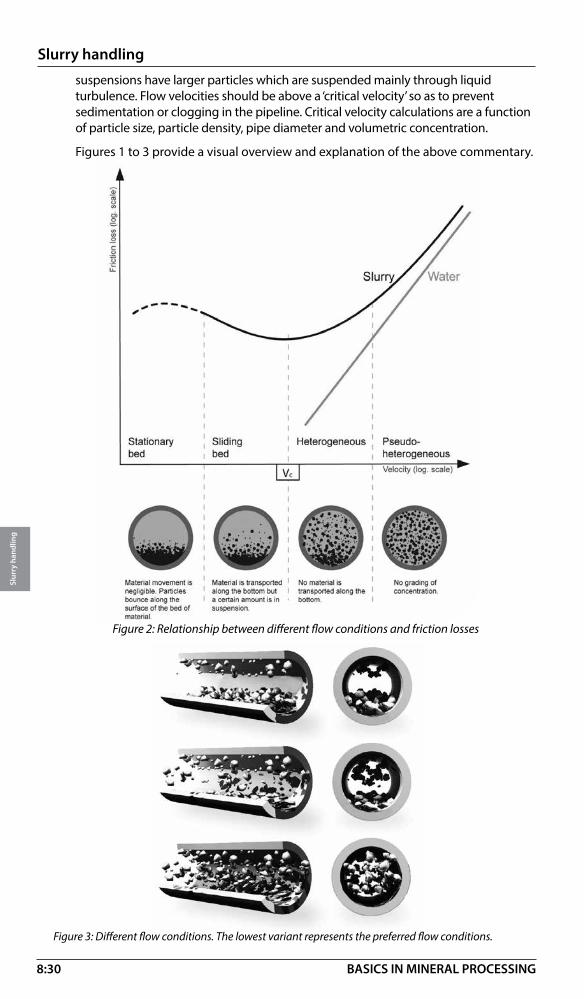
8:30
Slurry handling
Slur
ry h
andl
ing
BASICS IN MINERAL PROCESSING
suspensions have larger particles which are suspended mainly through liquid turbulence. Flow velocities should be above a ‘critical velocity’ so as to prevent sedimentation or clogging in the pipeline. Critical velocity calculations are a function of particle size, particle density, pipe diameter and volumetric concentration.
Figures 1 to 3 provide a visual overview and explanation of the above commentary.
Figure 2: Relationship between different flow conditions and friction losses
Figure 3: Different flow conditions. The lowest variant represents the preferred flow conditions.
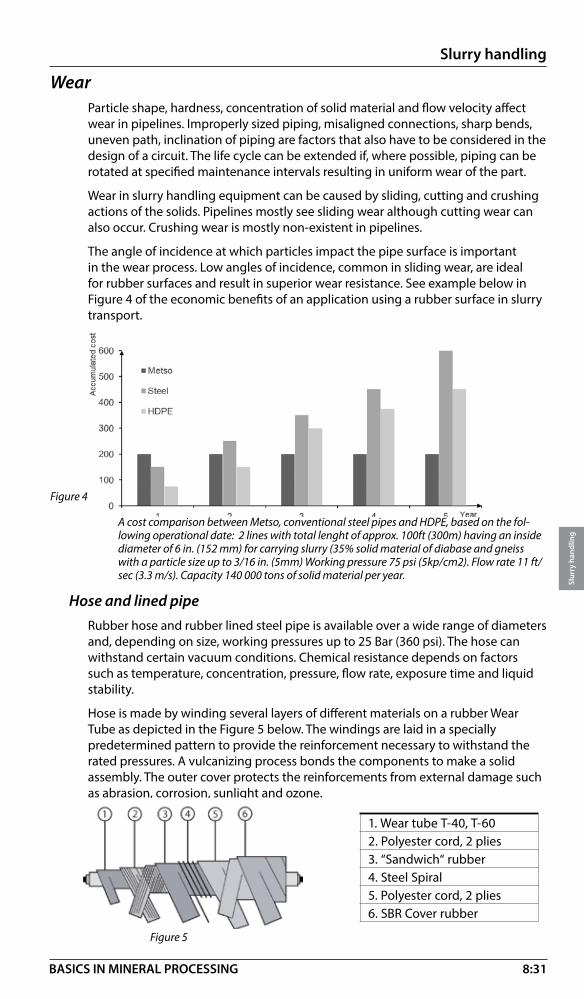
8:31
Slurry handling
Slur
ry h
andl
ing
BASICS IN MINERAL PROCESSING
WearParticle shape, hardness, concentration of solid material and flow velocity affect wear in pipelines. Improperly sized piping, misaligned connections, sharp bends, uneven path, inclination of piping are factors that also have to be considered in the design of a circuit. The life cycle can be extended if, where possible, piping can be rotated at specified maintenance intervals resulting in uniform wear of the part.
Wear in slurry handling equipment can be caused by sliding, cutting and crushing actions of the solids. Pipelines mostly see sliding wear although cutting wear can also occur. Crushing wear is mostly non-existent in pipelines.
The angle of incidence at which particles impact the pipe surface is important in the wear process. Low angles of incidence, common in sliding wear, are ideal for rubber surfaces and result in superior wear resistance. See example below in Figure 4 of the economic benefits of an application using a rubber surface in slurry transport.
Figure 4
Hose and lined pipeRubber hose and rubber lined steel pipe is available over a wide range of diameters and, depending on size, working pressures up to 25 Bar (360 psi). The hose can withstand certain vacuum conditions. Chemical resistance depends on factors such as temperature, concentration, pressure, flow rate, exposure time and liquid stability.
Hose is made by winding several layers of different materials on a rubber Wear Tube as depicted in the Figure 5 below. The windings are laid in a specially predetermined pattern to provide the reinforcement necessary to withstand the rated pressures. A vulcanizing process bonds the components to make a solid assembly. The outer cover protects the reinforcements from external damage such as abrasion, corrosion, sunlight and ozone.
A cost comparison between Metso, conventional steel pipes and HDPE, based on the fol-lowing operational date: 2 lines with total lenght of approx. 100ft (300m) having an inside diameter of 6 in. (152 mm) for carrying slurry (35% solid material of diabase and gneiss with a particle size up to 3/16 in. (5mm) Working pressure 75 psi (5kp/cm2). Flow rate 11 ft/sec (3.3 m/s). Capacity 140 000 tons of solid material per year.
Figure 5
1. Wear tube T-40, T-602. Polyester cord, 2 plies3. “Sandwich“ rubber4. Steel Spiral5. Polyester cord, 2 plies6. SBR Cover rubber

8:32
Slurry handling
Slur
ry h
andl
ing
BASICS IN MINERAL PROCESSING
Rubber lined steel pipe can be used in straight runs and can be self-supporting whereas a support structure is recommended for hose. The pipe and hose can be connected with the aid of split-flange couplings and gaskets for an obstruction free joint.
Other accessories such as bends, branch pipes, reducers, compensators and dart valves are available and provide the flexibility required to build a complete circuit. Figures 6 - 9 and pictures 1-5 illustrate several piping components and piping layouts.
Figure 6: Branch Pipe 90° Figure 7: Compensator Figure 8: Branch Pipe 45°
5 4
3
21
Figure 9: Example of Slurry hose piping and connectors
1. Rubber Lined Steel Pipe2. Coupling
3. 3xD Rubber Bend
4. Rubber Lined Steel Reducer
5. Branch Pipe
Accessories:
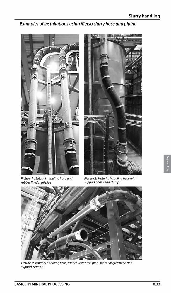
8:33
Slurry handling
Slur
ry h
andl
ing
BASICS IN MINERAL PROCESSING
Examples of installations using Metso slurry hose and piping
Picture 3: Material handling hose, rubber lined steel pipe, 3xd 90 degree bend and support clamps
Picture 1: Material handling hose and rubber lined steel pipe
Picture 2: Material handling hose with support beam and clamps

8:34
Slurry handling
Slur
ry h
andl
ing
BASICS IN MINERAL PROCESSING
Picture 4: Material handling hose with 3xD 90 degree bend
Picture 5: Rubber lined steel pipe and compensator

8:35
Slurry handling
Slur
ry h
andl
ing
BASICS IN MINERAL PROCESSING
Picture 5: Rubber lined steel pipe and compensator
Slurry valves – IntroductionValves are a necessity in any piping circuit. They aid in controlling flow in all types of operating conditions, from start-up, during production cycles and at shut-down.
Valves come in many designs, such as gate, pinch, ball, butterfly and plug to name a few. Operation can be manual, pneumatic, hydraulic or electric. Additional features can be added to automate the control process and optimize performance.
Valves handling solids laden fluids, as compared to those for clear fluids, face severe performance demands and they have to be of a robust design to function reliably in order to withstand the wear and tear that can occur in such applications. Valve designs are therefore limited to specific types as is described here.
ApplicationsSlurry valves are used in many mineral processing applications and some of the industries served are listed below.
Slurry valve sizingValve and piping selection in slurry applications requires skilled system analysis and support from personnel with expertise in this field. The following factors have a significant effect on the selection and sizing of a slurry valve because they are related to the wear life, power consumption, maintenance and operating costs in an application.
• Mining
• Oil Sands
• Pulp and Paper
• Stone and Gravel
• Cement
• Chemical
• Steel Works
• Coal
Particle characteristics• Size
• Size distribution
• Shape
• Hardness
• Density (concentration)
• Temperature
Liquid characteristics• Density
• Viscosity
• Temperature
• pH

8:36
Slurry handling
Slur
ry h
andl
ing
BASICS IN MINERAL PROCESSING
Flow regimesSee page 8:29 Slurry transport for more information on this subject. Flow regimes in a circuit can be described as stationary bed, sliding bed, heterogeneous and homogeneous. Stationary and sliding bed conditions are not recommended. Homogeneous and heterogeneous flow conditions are preferred for slurry transport.
WearIn slurry handling applications, equipment will commonly see abrasive, erosive and corrosive wear. These three can occur individually or in combination depending on the factors given above. Valves, for example, can see:
Type of flow• Laminar or turbulent
• Heterogeneous or homogeneous
• Flow velocity
Pipe conditions• Pipe material or
pipe lining material
• Diameter
• Circuit layout – used to define valve location
• Abrasion when particles get trapped between surfaces moving relative to each other
• Erosion when particles impact surfaces at different angles and depends on conditions such as high flow velocities, cavitation, particle characteristics and valve setting
• Corrosion is due to chemical attack on materials that are incompatible with the fluid being pumped

8:37
Slurry handling
Slur
ry h
andl
ing
BASICS IN MINERAL PROCESSING
Slurry valves
Metso slurry valves used in mineral processing applications are of the following designs. Contact Metso application engineering for technical assistance in the selection process.
Knife gate valvesThese valves are suitable for most abrasive slurries and the ‘full-bore’ design with ‘shut-off’ isolation features offer bi-directional operational reliability. Actuation by manual, pneumatic or other means is possible.
In the open setting, the elastomeric seats seal tightly against each other when the gate is fully withdrawn out of the flow stream. Only the seats are exposed to the slurry while providing a full-bore opening and no area for media build up.
During the closing action the seats are axially separated and seal against the gate. Residue can be discharged from the bottom of the valve at the end of the cycle.
Open ClosedOpen
The table below lists sizes available and the pressure ratings.
Size range · DN 50 – DN 600 · ASME 2” – 24”
Pressure rating
Flange Max. differential pressure at ambient temperature
DN 50 – DN 400 10 barDN 450 – DN 600 5 barANSI 2” – 16” 150 psiANSI 18” – 24” 75 psi
Temperature rating and chemical resistance depend on the type of elastomer used. Contact Metso application engineering for details.

8:38
Slurry handling
Slur
ry h
andl
ing
BASICS IN MINERAL PROCESSING
Dart valvesDart valves are used for flow shut off inside sump tanks with vertical outlets. They are suitable for applications handling abrasive slurries, powders or granular substances. The valve and seat are elastomer lined over all the surfaces that come in contact with slurry. There is no flow restriction in the open position.
The inside diameter of the seat is the same as the Slurry Hose System offered by Metso. Valves from DN100 – DN600 mm (4”-24”) sizes in DIN flanges are available. Pneumatic, hydraulic or electrically operated actuators can be used for regulating the dart valve.
Examples of Metso slurry hose and valve installations.
1. Metso 3xD Bend 90°2. Branch Pipe K453. Knife Gate Valve4. Rubber Lined Steel Pipe5. Rubber Lined Steel Reducer6. Sliding Support Clamp7. Alu Coupling8. Material Handling Hose9. Flange Adaptor10. Support Clamp11. Trellex Gasket
1. Flange Adapter2. Rubber Lined Steel Reducer3. Branch Pipe T90 inlet water4. Branch Pipe T90 drainage5. Metso 3xD Bend6. Metso Dart Valve Seat7. Metso Dart Valve
1. Flange Adapter2. Rubber Lined Steel Reducer3. Rubber Compensator4. Branch Pipe T90 inlet water5. Branch Pipe T90 drainage6. Knife Gate Valve
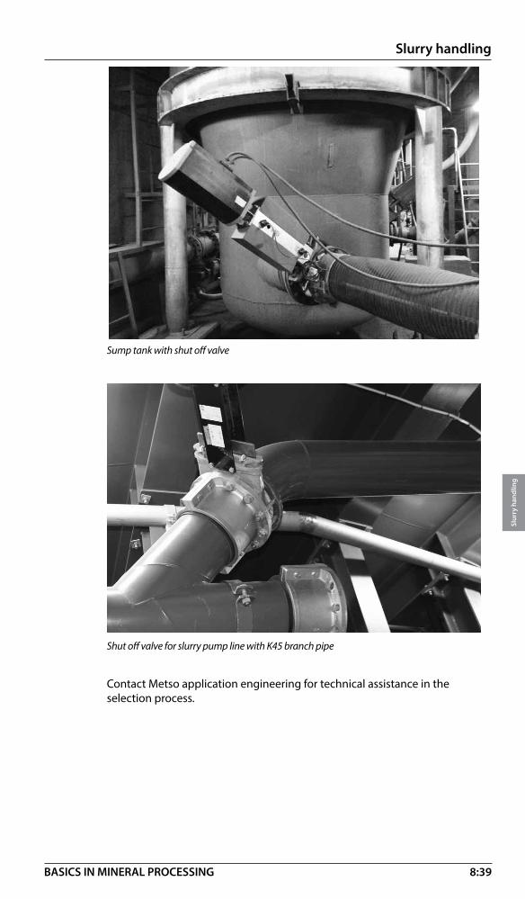
8:39
Slurry handling
Slur
ry h
andl
ing
BASICS IN MINERAL PROCESSING
Sump tank with shut off valve
Shut off valve for slurry pump line with K45 branch pipe
Contact Metso application engineering for technical assistance in the selection process.
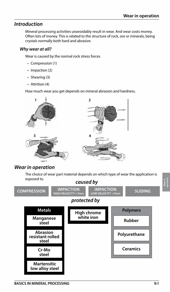
9:1
Wear in operation
Wea
r in
op
erat
ion
BASICS IN MINERAL PROCESSING
IntroductionMineral processing activities unavoidably result in wear. And wear costs money. Often lots of money. This is related to the structure of rock, ore or minerals, being crystals normally both hard and abrasive.
Why wear at all?Wear is caused by the normal rock stress forces
• Compression (1)
• Impaction (2)
• Shearing (3)
• Attrition (4)
How much wear you get depends on mineral abrasion and hardness.
Wear in operation
COMPRESSION
Metals
Manganesesteel
SLIDINGIMPACTIONLOW VELOCITY <7m/s
IMPACTIONHIGH VELOCITY >7m/s
Polymers
Rubber
Polyurethane
Ceramics
1 2
3 4
caused by
Cr-Mosteel
The choice of wear part material depends on which type of wear the application is exposed to.
Abrasion resistant rolled
steel
Martensitic low alloy steel
protected by
High chromewhite iron

9:2
Wear in operation
Wea
r in
op
erat
ion
BASICS IN MINERAL PROCESSING
COMPRESSION
Manganesesteel
SLIDINGIMPACTIONLOW VELOCITY <7m/s
IMPACTIONHIGH VELOCITY >7m/s
High chromewhite iron
Wear by compression
Applications: Crushers
Gyratory
Cone
Jaw
Manganese steel: The first option for compression wear is manganese steel. This alloy has a very special property, being self hardening and self healing when exposed to large amounts of compression and impact energy.Normal standard is a 14% Mn alloy which is first option in most crushing applications.18% Mn alloy is a harder but also a more brittle. This alloy is used in applications where the rock is softer (limited self hardening) but very abrasive.
Restrictions:When installed in applications without work hardening service life will be poor! Martensitic low alloy steel: These steels have been
}COMPRESSION
Manganesesteel
SLIDINGIMPACTIONLOW VELOCITY <7m/s
IMPACTIONHIGH VELOCITY >7m/s
High chromewhite iron
Grinding mills Slurry pumps
HSI
VSI
Manganese: Needs high impaction for self hardening. If impaction is getting lower and sliding is increasing Manganese is not suitable.Abrasion resistant rolled steel: Even more wear and impact resitant than Cr-MoCr-Mo: Used in grinding when white iron is too brittle.High chrome white iron: Opposite to manganese, can take heavy sliding but is very fragile and therefore limited against impaction. In mills only used in low impact applicationsPoly-Met: A combination of rubber and wear resistant metallic alloys is often an alternative to an all metallic lining in high impact grinding mills as the rubber will absorb the impact and prevent cracking of the metal.Note! The use of chrome steel (less brittle than chrome iron) is increasing for liners, curtains and hammers.
}
Wear by impaction (high)
Applications: Impactors
Martensitic low alloy steel
Cr-Mo
Abrasion resistant rolled
steel
PolyMet
tailored for various solutions having optimum microstructure with sufficient hardness and toughness achieved by heat treatment process. Precise control of time and temperature are the key parameters. Concerning wear these steels give the sufficient hardness and toughness combination with economical way. Typical applications are primary gyratory wear concaves.High chrome white iron:The wear resistance is based on the hard carbides on the relative hard matrix, still the composition and structure can be tailored considerably. Generally high chromium irons are commonly used in abrasive wear applications. Typical applications are primary gyratory concaves. The alloys of cast ”white iron” type (High-chrome and Ni-hard) shall be avoided in crushers submitted to heavy compression.
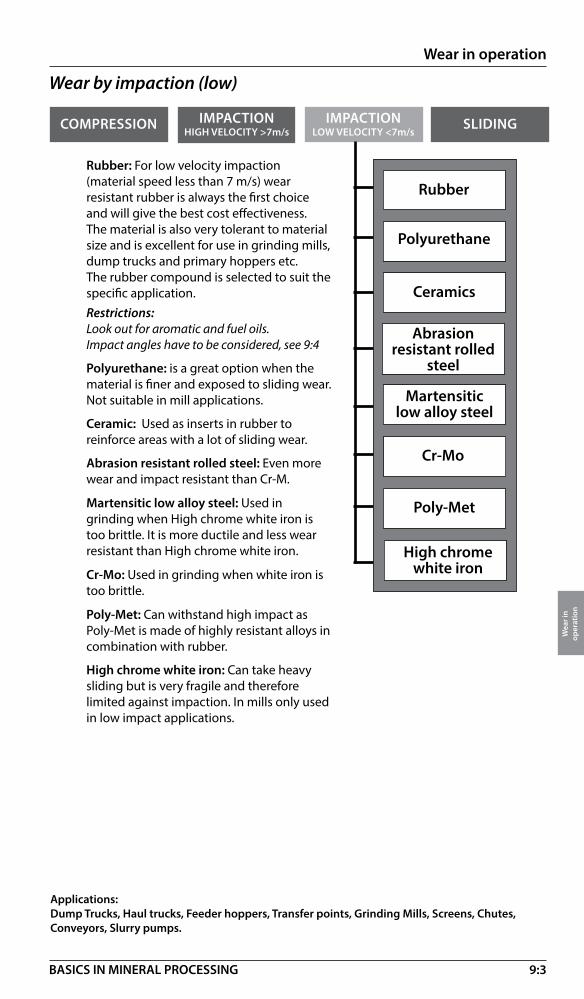
9:3
Wear in operation
Wea
r in
op
erat
ion
BASICS IN MINERAL PROCESSING
COMPRESSION SLIDINGIMPACTIONLOW VELOCITY <7m/s
IMPACTIONHIGH VELOCITY >7m/s
Wear by impaction (low)
Applications: Dump Trucks, Haul trucks, Feeder hoppers, Transfer points, Grinding Mills, Screens, Chutes, Conveyors, Slurry pumps.
Rubber: For low velocity impaction (material speed less than 7 m/s) wear resistant rubber is always the first choice and will give the best cost effectiveness. The material is also very tolerant to material size and is excellent for use in grinding mills, dump trucks and primary hoppers etc.The rubber compound is selected to suit the specific application.Restrictions:Look out for aromatic and fuel oils.Impact angles have to be considered, see 9:4
Polyurethane: is a great option when the material is finer and exposed to sliding wear. Not suitable in mill applications.
Ceramic: Used as inserts in rubber to reinforce areas with a lot of sliding wear.
Abrasion resistant rolled steel: Even more wear and impact resistant than Cr-M.
Martensitic low alloy steel: Used in grinding when High chrome white iron is too brittle. It is more ductile and less wear resistant than High chrome white iron.
Cr-Mo: Used in grinding when white iron is too brittle.
Poly-Met: Can withstand high impact as Poly-Met is made of highly resistant alloys in combination with rubber.
High chrome white iron: Can take heavy sliding but is very fragile and therefore limited against impaction. In mills only used in low impact applications.
Rubber
Polyurethane
Ceramics
Abrasion resistant rolled
steel
Martensitic low alloy steel
Cr-Mo
Poly-Met
High chromewhite iron
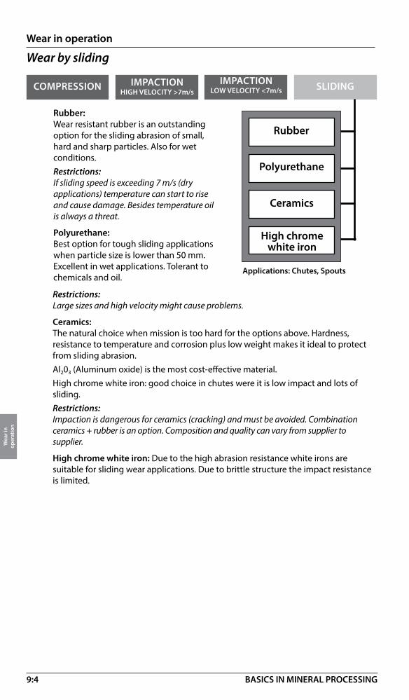
9:4
Wear in operation
Wea
r in
op
erat
ion
BASICS IN MINERAL PROCESSING
COMPRESSION
Rubber
SLIDINGIMPACTIONLOW VELOCITY <7m/s
IMPACTIONHIGH VELOCITY >7m/s
Polyurethane
Ceramics
Wear by sliding
Applications: Chutes, Spouts
Rubber:Wear resistant rubber is an outstanding option for the sliding abrasion of small, hard and sharp particles. Also for wet conditions.Restrictions:If sliding speed is exceeding 7 m/s (dry applications) temperature can start to rise and cause damage. Besides temperature oil is always a threat.
Polyurethane:Best option for tough sliding applications when particle size is lower than 50 mm. Excellent in wet applications. Tolerant to chemicals and oil.
Restrictions:Large sizes and high velocity might cause problems.
Ceramics:The natural choice when mission is too hard for the options above. Hardness, resistance to temperature and corrosion plus low weight makes it ideal to protect from sliding abrasion.Al203 (Aluminum oxide) is the most cost-effective material. High chrome white iron: good choice in chutes were it is low impact and lots of sliding.Restrictions:Impaction is dangerous for ceramics (cracking) and must be avoided. Combination ceramics + rubber is an option. Composition and quality can vary from supplier to supplier.
High chrome white iron: Due to the high abrasion resistance white irons are suitable for sliding wear applications. Due to brittle structure the impact resistance is limited.
High chromewhite iron

9:5
Wear in operation
Wea
r in
op
erat
ion
BASICS IN MINERAL PROCESSING
Wear protection – Wear lining and sheeting
Lining system overview
Selection guideThe selection guide for lining solutions is divided into threesections: wear improvements, flow improvements and noisereduction. Pick your critical areas for improvement and let theselection guide help you find the product that brings the mostvalue to your application.Your choice will be based on processing conditions, materialsize, shape, drop height, volume, angle of impact, etc.
General wear improvement lining guideImprove wear life of lining applications with Metso lining products. We offer awide range of various lining products suitable for any application – wet or dryapplication, small or large material size and different impact angles.Below you find an overview of products for various applications. Someproducts overlap and can be used in the same application.
Handledmtrl size
Large
Trellex Poly Cer
Trellex SQ/ Trellex Flexback
Trellex PP
Trellex PT
Trellex SB
Trellex SQ/ Trellex Flexback
90 O Impact
angle
Small 0O

9:6
Wear in operation
Wea
r in
op
erat
ion
BASICS IN MINERAL PROCESSING
General flow improvement lining guideLining products for flow improvement are available in a range of options, based onhigh wear and capacity.Below you will find an overview of products for various areas of use. Some productsoverlap and can be used in various applications.
General noise-reduction lining guideExcessive noise is a problem in mining and construction operations. Managingnoise pollution is more important than ever. All wear rubber products such as Trellex PP, Trellex SP, Trellex PT, Trellex SB, Trellex WB, Trellex SQ, Trellex Flexback and Trellex Poly-Cer will contribute to reducing noise levels by up to 20 decibel. Reducing the noise by 10 decibel corresponds to the effect of cutting the noise by half. Less noise means better work conditions. See also page 10:5
Abrasion rate
High
LowLow High Capacity
Trellex Poly-Cer
Trellex LFTrellex PPU
Hz
dB (A)120
110
100
90
80
70
60
50
31,5 63 125
250
500
1000
2000
4000
8000
1600
0
3150
0
Noise protection requiredSteel lining
Trellex rubber lining
Diagram sound level - Loading truck
Hz
dB (A)120
110
100
90
80
70
60
50
31,5 63 125
250
500
1000
2000
4000
8000
1600
0
3150
0
Diagram sound level - Loading truck
Noise protection requiredSteel lining
Trellex rubber lining
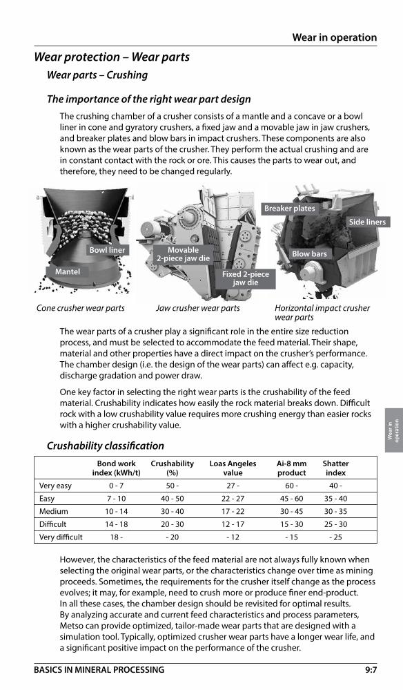
9:7
Wear in operation
Wea
r in
op
erat
ion
BASICS IN MINERAL PROCESSING
Wear parts – Crushing
The importance of the right wear part designThe crushing chamber of a crusher consists of a mantle and a concave or a bowl liner in cone and gyratory crushers, a fixed jaw and a movable jaw in jaw crushers, and breaker plates and blow bars in impact crushers. These components are also known as the wear parts of the crusher. They perform the actual crushing and are in constant contact with the rock or ore. This causes the parts to wear out, and therefore, they need to be changed regularly.
Wear protection – Wear parts
The wear parts of a crusher play a significant role in the entire size reduction process, and must be selected to accommodate the feed material. Their shape, material and other properties have a direct impact on the crusher’s performance. The chamber design (i.e. the design of the wear parts) can affect e.g. capacity, discharge gradation and power draw.
One key factor in selecting the right wear parts is the crushability of the feed material. Crushability indicates how easily the rock material breaks down. Difficult rock with a low crushability value requires more crushing energy than easier rocks with a higher crushability value.
Crushability classification
Cone crusher wear parts Jaw crusher wear parts Horizontal impact crusher wear parts
Bond work Crushability Loas Angeles Ai-8 mm Shatter index (kWh/t) (%) value product index
Very easy 0 - 7 50 - 27 - 60 - 40 -
Easy 7 - 10 40 - 50 22 - 27 45 - 60 35 - 40
Medium 10 - 14 30 - 40 17 - 22 30 - 45 30 - 35
Difficult 14 - 18 20 - 30 12 - 17 15 - 30 25 - 30
Very difficult 18 - - 20 - 12 - 15 - 25
However, the characteristics of the feed material are not always fully known when selecting the original wear parts, or the characteristics change over time as mining proceeds. Sometimes, the requirements for the crusher itself change as the process evolves; it may, for example, need to crush more or produce finer end-product. In all these cases, the chamber design should be revisited for optimal results. By analyzing accurate and current feed characteristics and process parameters, Metso can provide optimized, tailor-made wear parts that are designed with a simulation tool. Typically, optimized crusher wear parts have a longer wear life, and a significant positive impact on the performance of the crusher.
Breaker plates
Side liners
Blow barsBowl liner
Mantel
Movable 2-piece jaw die
Fixed 2-piece jaw die
Noise protection requiredSteel lining
Trellex rubber lining

9:8
Wear in operation
Wea
r in
op
erat
ion
BASICS IN MINERAL PROCESSING
Fact
ors a
ffect
ing
wea
r life
Whe
n it
com
es to
the
lifet
ime
of c
rush
er w
ear p
arts
, lon
ger i
s us
ually
alw
ays
bett
er.
Exte
ndin
g th
e w
ear l
ife o
f the
par
ts in
crea
ses
the
uptim
e of
the
crus
her,
as fe
wer
m
aint
enan
ce s
tops
are
nee
ded.
Hig
her u
ptim
e ge
nera
lly lo
wer
s th
e op
erat
ing
expe
nses
of a
pla
nt, m
akin
g it
mor
e pr
ofita
ble.
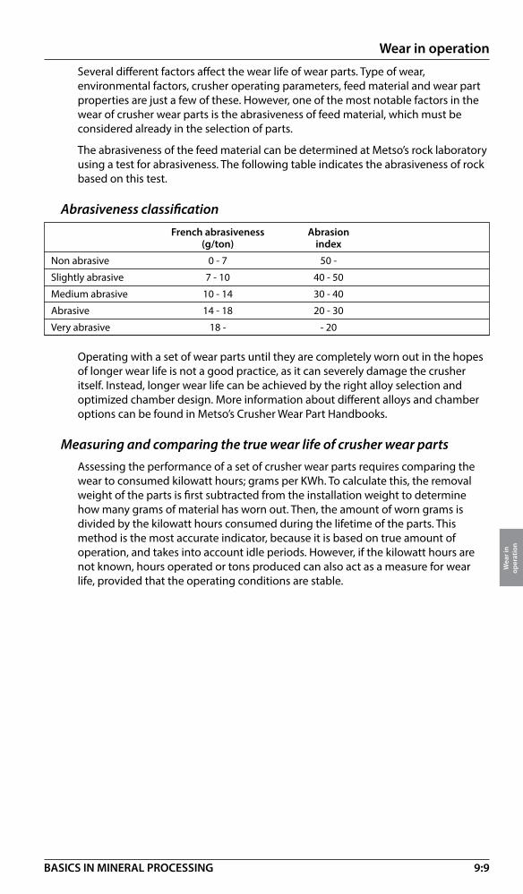
9:9
Wear in operation
Wea
r in
op
erat
ion
BASICS IN MINERAL PROCESSING
Several different factors affect the wear life of wear parts. Type of wear, environmental factors, crusher operating parameters, feed material and wear part properties are just a few of these. However, one of the most notable factors in the wear of crusher wear parts is the abrasiveness of feed material, which must be considered already in the selection of parts.
The abrasiveness of the feed material can be determined at Metso’s rock laboratory using a test for abrasiveness. The following table indicates the abrasiveness of rock based on this test.
Abrasiveness classification French abrasiveness Abrasion (g/ton) index
Non abrasive 0 - 7 50 -
Slightly abrasive 7 - 10 40 - 50
Medium abrasive 10 - 14 30 - 40
Abrasive 14 - 18 20 - 30
Very abrasive 18 - - 20
Operating with a set of wear parts until they are completely worn out in the hopes of longer wear life is not a good practice, as it can severely damage the crusher itself. Instead, longer wear life can be achieved by the right alloy selection and optimized chamber design. More information about different alloys and chamber options can be found in Metso’s Crusher Wear Part Handbooks.
Measuring and comparing the true wear life of crusher wear partsAssessing the performance of a set of crusher wear parts requires comparing the wear to consumed kilowatt hours; grams per KWh. To calculate this, the removal weight of the parts is first subtracted from the installation weight to determine how many grams of material has worn out. Then, the amount of worn grams is divided by the kilowatt hours consumed during the lifetime of the parts. This method is the most accurate indicator, because it is based on true amount of operation, and takes into account idle periods. However, if the kilowatt hours are not known, hours operated or tons produced can also act as a measure for wear life, provided that the operating conditions are stable.

9:10
Wear in operation
Wea
r in
op
erat
ion
BASICS IN MINERAL PROCESSING
Screening media – ScreeningSelection of the correct size and type of screen is important. Equally important is the selection of the screening media. This refers not only to a correct aperture related to the ”cut size ”, but also to the wear in operation of these screens.
See more information; page 4:4
Self supporting rubber panels Rubber & polyurethane tension mats
Rubber & polyurethane bolt down panels Antiblinding rubber mats
Rubber / polyurethane modular systems

9:11
Wear in operation
Wea
r in
op
erat
ion
BASICS IN MINERAL PROCESSING
Rubber linings Poly-Met® linings
Orebed® liningsMetallic linings
Mill liningThe choice of mill lining depends on application objectives and current operating conditions.
Rubber lining has benefits such as low weight, no leakage or peening and it significantly reduces the noise level. Poly-Met linings combines steel and rubber. It allows the use of more resistant alloys of iron and steel than can be used in a conventional metallic lining, as the rubber substantially dampens the impact forces. Metallic linings offer total freedom of design and can be made in different alloys in order to maximize performance based on operating data. The Orebed lining consists of a series of powerful magnets embedded in rubber. The ferromagnetic material in the mill load forms a layer that protects the lining.
A combination between the different mill lining materials can often be the best solution. Using each material where it performs the best in order to optimize the grinding process.

9:12
Wear in operation
Wea
r in
op
erat
ion
BASICS IN MINERAL PROCESSING
Tumbling mill – typical mill lining componentsLinings for mills
1. 2. 3. 4. 5.
6. 7. 8. 9. 10.
Lining from millsThis is a general view of suitable linings. Please contact Metso for more detailed information.
40
38
34
30
26
22
18
14
10
6
0
Type of mill AG SAG Ball Rod Pebble Continuous Batch
Mill sizem ft
Discharge systems, trunnion linings and trommel screens are suitable for all sizes.
Rub
Poly
-Met
Met
allic
Rubb
er
Poly
-Met
Met
allicRu
bber
Poly
-Met
Met
allic
Rubb
er
Poly
-Met
Met
allic
Rubb
er
Poly
-Met
Ore
bed
Ru
Rubb
er
12
11,5
10
9
8
7
5,5
4
3
2
0
Lining life time – typical linings “ball park figures”
Type of mill MonthsAG 8 – 15SAG 3 – 12Rod 6 – 24Ball 6 – 36Pebble 12 – 48
Type of Mining Mining Power plants, Mining, Mining, Ceramic Ceramicindustry cement, aggregate, minerals mining, minerals minerals
Trommel screensThe frame and the replaceable trommel panels is protected by a wear resistant rubber or polyurethane layer.
Discharger Grate plate Lifter bar Support segment Filling segment
Shell plate Head plate Mandoor plate Trunnion liner Centre cone

9:13
Wear in operation
Wea
r in
op
erat
ion
BASICS IN MINERAL PROCESSING
AG mills SAG mills
Rod mills
Dry: White iron or Cr-MoWet: White iron, Cr-Mo or Poly-Met
Dry: Cr-MoWet: Cr-Mo or Poly-Met
Dry: White iron or Cr-MoWet: White iron Rubber and Poly-Met, or Cr-Mo Head liners in rod mills are always Cr-Mo
Primary or secondary mills: Rubber, Poly-Met, white iron or Cr-Mo. Select type of insert based on level of impact in the mill. Regrind: Rubber
Tumbling mill liners – material
Ball and Pebble mills
Screw with liners
Magnetic lining
VERTIMILL® mill liners – material
Screw: White ironChamber:Orebed magnetic liners.
Impeller arms
Side and base liner
SMD mill liners – material
Side and base liner:RubberRubber impeller arms:Rubber
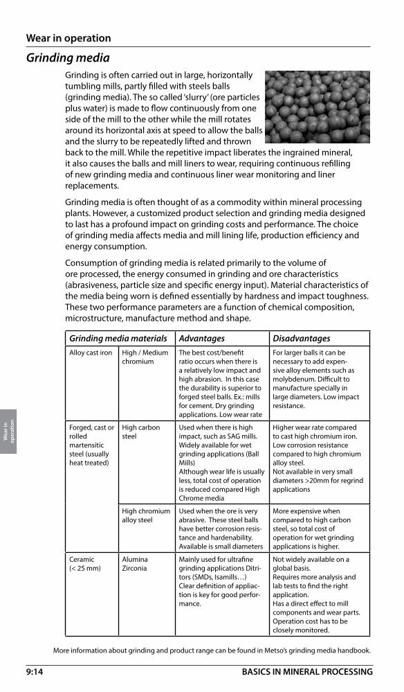
9:14
Wear in operation
Wea
r in
op
erat
ion
BASICS IN MINERAL PROCESSING
Grinding mediaGrinding is often carried out in large, horizontally tumbling mills, partly filled with steels balls (grinding media). The so called ‘slurry’ (ore particles plus water) is made to flow continuously from one side of the mill to the other while the mill rotates around its horizontal axis at speed to allow the balls and the slurry to be repeatedly lifted and thrown back to the mill. While the repetitive impact liberates the ingrained mineral, it also causes the balls and mill liners to wear, requiring continuous refilling of new grinding media and continuous liner wear monitoring and liner replacements.
Grinding media is often thought of as a commodity within mineral processing plants. However, a customized product selection and grinding media designed to last has a profound impact on grinding costs and performance. The choice of grinding media affects media and mill lining life, production efficiency and energy consumption.
Consumption of grinding media is related primarily to the volume of ore processed, the energy consumed in grinding and ore characteristics (abrasiveness, particle size and specific energy input). Material characteristics of the media being worn is defined essentially by hardness and impact toughness. These two performance parameters are a function of chemical composition, microstructure, manufacture method and shape.
Grinding media materials Advantages DisadvantagesAlloy cast iron High / Medium
chromiumThe best cost/benefit ratio occurs when there is a relatively low impact and high abrasion. In this case the durability is superior to forged steel balls. Ex.: mills for cement. Dry grinding applications. Low wear rate
For larger balls it can be necessary to add expen-sive alloy elements such as molybdenum. Difficult to manufacture specially in large diameters. Low impact resistance.
Forged, cast or rolled martensitic steel (usually heat treated)
High carbon steel
Used when there is high impact, such as SAG mills.Widely available for wet grinding applications (Ball Mills) Although wear life is usually less, total cost of operation is reduced compared High Chrome media
Higher wear rate compared to cast high chromium iron. Low corrosion resistance compared to high chromium alloy steel.Not available in very small diameters >20mm for regrind applications
High chromium alloy steel
Used when the ore is very abrasive. These steel balls have better corrosion resis-tance and hardenability.Available is small diameters
More expensive when compared to high carbon steel, so total cost of operation for wet grinding applications is higher.
Ceramic(< 25 mm)
Alumina Zirconia
Mainly used for ultrafine grinding applications Ditri-tors (SMDs, Isamills…)Clear definition of appliac-tion is key for good perfor-mance.
Not widely available on a global basis.Requires more analysis and lab tests to find the right application.Has a direct effect to mill components and wear parts. Operation cost has to be closely monitored.
More information about grinding and product range can be found in Metso’s grinding media handbook.

9:15
Wear in operation
Wea
r in
op
erat
ion
BASICS IN MINERAL PROCESSING
Wear parts – Slurry pumpsAlthough the size of solids in a slurry is smaller than the feed size to a crusher or a grinding mill, wear represents a high operation cost for slurry pumping. This is naturally related to the high dynamic energy input in the form of high tip speed of the pump impeller causing both sliding and impaction wear.
Wear material vs size
Wear parts pumps – metalHigh chrome iron (600Br) can be used at Ph down to 2.5. Standard wear material for most pump ranges.
Ni – hard with hardness exceeding 600 Br used mainly as casing material for pumps in grinding circuits or dredging.
High density frozen Ni-hard with hardness up to 900 Br used as casing material in primary grinding circuits.
Manganese steel with hardness up to 350 Br used for dredging applications.
Size 1m 1 dm 1 cm 1 mm 100 micron 10 micron 1 micron
LIM
IT F
OR
HYD
RAU
LIC
TRA
NSP
ORT HIGH CHROME
LIM
IT F
OR
HA
RD IR
ON
S
LIM
IT F
OR
RUBB
ER L
INER
S
LIM
IT F
OR
RUBB
ER IM
PELL
ERSMANGANESE
STEEL

9:16
Wear in operation
Wea
r in
op
erat
ion
BASICS IN MINERAL PROCESSING
Material Physical Chemical Thermal
properties properties properties
Max. Wear Hot water, Strong and Oils, Highest service Impeller Tip resistance diluted acids oxidising hydro temp.(oC) Speed acids carbons Contin. Occasion. (m/s)
Natural Rubbers 27 Very good Excellent Fair Bad (-50) to 65 100
Chloroprene 452 27 Good Excellent Fair Good 90 120
EPDM 016 30 Good Excellent Good Bad 100 130
Butyl 30 Fair Excellent Good Bad 100 130
Polyurethane 30 Very good Fair Bad Good (-15) to 45-50 65
Wear parts pumps – elastomers
Something about ceramic linersAlthough ceramics have high resistance against wear, temperature and most chemicals, they have never really been accepted as day-to-day standards in Slurry Pumping.
Being both brittle and expensive to manufacture.
Development work on ceramics continue in an attempt to improve the possible acceptance.

9:17
Wear in operation
Wea
r in
op
erat
ion
BASICS IN MINERAL PROCESSING
Wear in slurry pipelinesIt is not easy to compare wear rates for different materials in a slurry pipeline depending on variations in duty. As a guide the figures below can be used (Transport and Road Research Laboratory test report of wear in slurry pipelines).
From the first of two programs of wear tests, the following conclusions were reached:
– Over the range investigated (2 to 6 m/s) wear varied according to a power between the square and cube of the velocity.
– Over the range investigated (5 to 15% by volume) wear varied more or less linearly with concentration.
– Over the range investigated (0.015 to 1.5 mm) wear varied more or less linearly with particle size.
– Emery (Mohs Hardness 8 to 9) produced a wear rate several times greater than that for silica sand (Mohs hardness 6 to 7).
In the second program the operating conditions were kept constant (velocity 4 m/s, 10% slurry) while 18 different pipe materials were compared.
Among them, three were rubber “a” (Trellex T40) - rubber “b” (Trellex T60) and rubber “c” (a British make).
Material Wear rate Life expectancy (mm/year) of a 5 mm thick tube (years)Rubber “a” (Trellex T40) 0.13 38
Zirconia/alumina ceramic 0.15 33
Ni-hard steel 0.19 26
Polyurethane “a” 0.20 25
Polyurethane “b” 0.22 22
Rubber “b” (Trellex T60) 0.35 14
Sintered alumina 0.40 12
Rubber “c” (not Trellex) 0.61 8
High Density polyurethane “b” 0.67 7
High density polyvinyl chloride 0.87 5
Unplasticised polyvinyl chloride 1.27 4
Stainless steel 1.29 4
Mild steel “a” 1.57 3
Polypropylene 1.59 3
Mild steel “b” 1.69 3
ABS 2.52 2
Asbestos/cement 94.68 –

10:1
Operation and environment
Ope
ratio
n an
d en
viro
nmen
t
BASICS IN MINERAL PROCESSING
Operation and environment – IntroductionFrom environmental, health and safety point of view most mineral processing operations have some negative effects on the working environment.
The main problems are related to
• Dust (dry plants)
• Noise (wet and dry plants)
• Pollution (emissions other than dust to air and water)
Regarding pollution of water and air by various emissions we refer to the process sections 5 and 6 above (enrichment and upgrading).
Dust
Dust – SizeWhen energy is introduced to rock, ore or mineral crystals will generate a dust emission. With dust in mineral processing we practically understand particles below 100 micron in size. Above this size dry particles are easy to control and are quite harmless.
Dust – Chemical compositionA parameter of interest is the chemical composition. Hard rock in many cases is hazardous due to the silica content.
Free quarts (SiO2) is extremely dangerous and so are the rocks containing quarts like granite, gneiss a.o, see figure below. Fine silica can cause silicosis, a deadly lung disease. Mg-silicate of asbestos type is also very dangerous when inhaled, causing lung cancer.
As many of the silicates are hard and abrasive these dust fractions also are causing heavy wear when exposed to bearings, motors etc.
Dust fractions of non - silica type are normally not too dangerous for the operators and give more like a “housekeeping” problem.
Gra
nite
Rhy
olite
Dio
rite
And
esite
Gab
bro
Basa
lt
SiO2
Abrasion curve
K-Feldspar
Quartz
Na, Ca F
eldspar
Ferromagnesia
n minerals
70% SiO2 by weight
60
50
40
100% Mineral by volume
Surface (fine)
Deep (coarse)
Biotite Olivine
Dust – SiO2 levels
SiO2 levels in magmatic rock
80
60
40
20
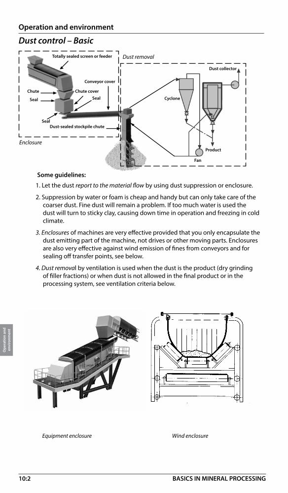
10:2
Operation and environment
Ope
ratio
n an
d en
viro
nmen
t
BASICS IN MINERAL PROCESSING
Dust control – Basic
1. Let the dust report to the material flow by using dust suppression or enclosure.
2. Suppression by water or foam is cheap and handy but can only take care of the coarser dust. Fine dust will remain a problem. If too much water is used the dust will turn to sticky clay, causing down time in operation and freezing in cold climate.
3. Enclosures of machines are very effective provided that you only encapsulate the dust emitting part of the machine, not drives or other moving parts. Enclosures are also very effective against wind emission of fines from conveyors and for sealing off transfer points, see below.
4. Dust removal by ventilation is used when the dust is the product (dry grinding of filler fractions) or when dust is not allowed in the final product or in the processing system, see ventilation criteria below.
Cyclone
Fan
Product
Totally sealed screen or feeder
Chute coverSeal
Seal
Chute
Seal
Conveyor cover
Dust collector
Dust-sealed stockpile chute
Equipment enclosure Wind enclosure
Dust removal
Enclosure
Some guidelines:

10:3
Operation and environment
Ope
ratio
n an
d en
viro
nmen
t
BASICS IN MINERAL PROCESSING
Ventilation criteria Dust capture velocity in m/s (ft/min)
= Ventilation criteria (Vc) in m³/s/m² (ft³/min/ft²)
= Air volume needed per open area of enclosure
Calculation of ventilation systems for dust removal is a tricky thing. Some estimation figures below:
Application Vc Comments
Feeders, surge bin openings 1,02 (200) General value for low-energy operations
Transfer points 2,33 (1500) per enclosure area
Screens 0,26 (50) per screen area
Crushers and dry mills 1,5 (300) not for air swept mills
Dust collection The dust removal and dust collecting systems are very similar to a normal dry classification circuit. Dry classification is in fact a dust removal system where the max size of the dust is controlled by a classifier (or ventilation criteria), See below.
Primary recovery of dust is normally done in a cyclone taking the major part. The final recollection is done in a wet scrubber or a fabric filter.
Wet scrubber has an advantage over fabric filter when the dust is combustible. In all other cases the dry fabric filtration is more effective as no sludge handling is required (being the case with wet scrubbers).
Feedhopper
ClassifierDust
Collector
Cyclone
Mill
Fan
Product
Option“In circuit drying” Air heater
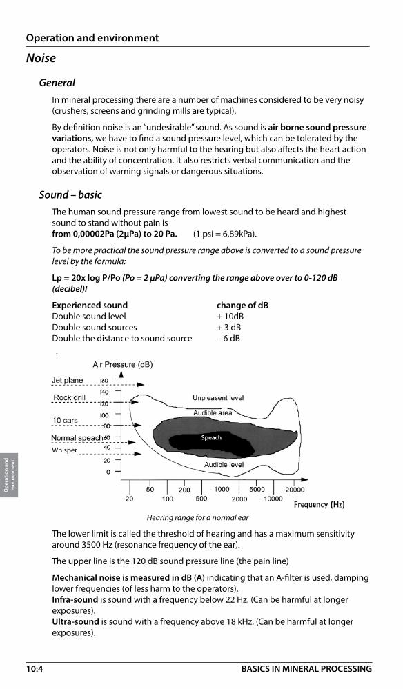
10:4
Operation and environment
Ope
ratio
n an
d en
viro
nmen
t
BASICS IN MINERAL PROCESSING
Noise
GeneralIn mineral processing there are a number of machines considered to be very noisy (crushers, screens and grinding mills are typical).
By definition noise is an “undesirable” sound. As sound is air borne sound pressure variations, we have to find a sound pressure level, which can be tolerated by the operators. Noise is not only harmful to the hearing but also affects the heart action and the ability of concentration. It also restricts verbal communication and the observation of warning signals or dangerous situations.
Sound – basicThe human sound pressure range from lowest sound to be heard and highest sound to stand without pain isfrom 0,00002Pa (2µPa) to 20 Pa. (1 psi = 6,89kPa).
To be more practical the sound pressure range above is converted to a sound pressure level by the formula:
Lp = 20x log P/Po (Po = 2 µPa) converting the range above over to 0-120 dB (decibel)!
Experienced sound change of dBDouble sound level + 10dBDouble sound sources + 3 dBDouble the distance to sound source – 6 dB
Hearing range for a normal ear
The lower limit is called the threshold of hearing and has a maximum sensitivity around 3500 Hz (resonance frequency of the ear).
The upper line is the 120 dB sound pressure line (the pain line)
Mechanical noise is measured in dB (A) indicating that an A-filter is used, damping lower frequencies (of less harm to the operators). Infra-sound is sound with a frequency below 22 Hz. (Can be harmful at longer exposures).Ultra-sound is sound with a frequency above 18 kHz. (Can be harmful at longer exposures).
Speach
Whisper
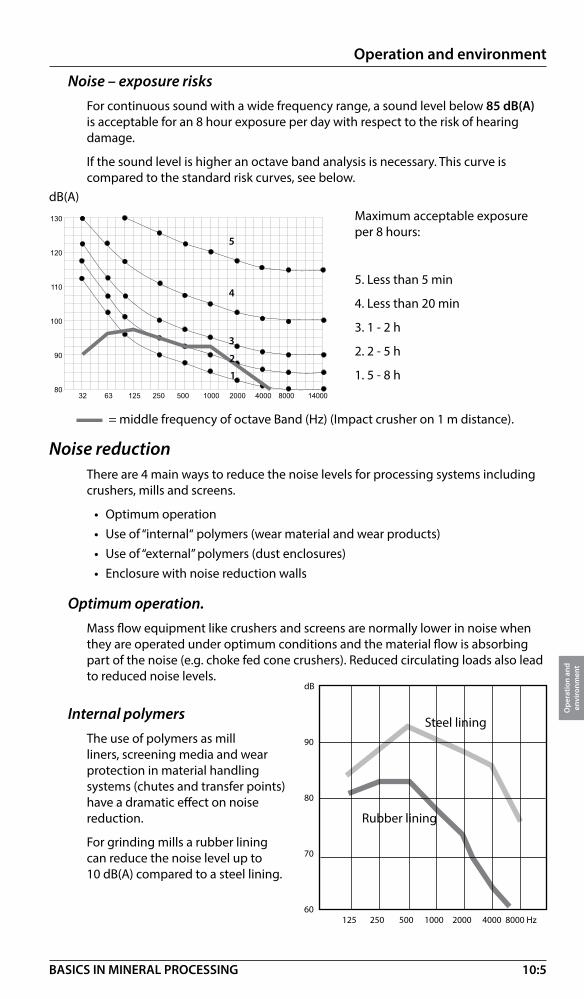
10:5
Operation and environment
Ope
ratio
n an
d en
viro
nmen
t
BASICS IN MINERAL PROCESSING
Noise reductionThere are 4 main ways to reduce the noise levels for processing systems including crushers, mills and screens.
• Optimum operation • Use of “internal“ polymers (wear material and wear products) • Use of “external” polymers (dust enclosures) • Enclosure with noise reduction walls
Optimum operation.Mass flow equipment like crushers and screens are normally lower in noise when they are operated under optimum conditions and the material flow is absorbing part of the noise (e.g. choke fed cone crushers). Reduced circulating loads also lead to reduced noise levels.
Noise – exposure risksFor continuous sound with a wide frequency range, a sound level below 85 dB(A) is acceptable for an 8 hour exposure per day with respect to the risk of hearing damage.
If the sound level is higher an octave band analysis is necessary. This curve is compared to the standard risk curves, see below.
���
���
���
���
��
���� ���� �������������������������������������������� ����� �������������������
= middle frequency of octave Band (Hz) (Impact crusher on 1 m distance).
Maximum acceptable exposure per 8 hours:
5. Less than 5 min
4. Less than 20 min
3. 1 - 2 h
2. 2 - 5 h
1. 5 - 8 h1
2
3
4
5
Internal polymersThe use of polymers as mill liners, screening media and wear protection in material handling systems (chutes and transfer points) have a dramatic effect on noise reduction.
For grinding mills a rubber lining can reduce the noise level up to 10 dB(A) compared to a steel lining.
dB
90
80
70
60125 250 500 1000 2000 4000 8000 Hz
dB(A)
Steel lining
Rubber lining
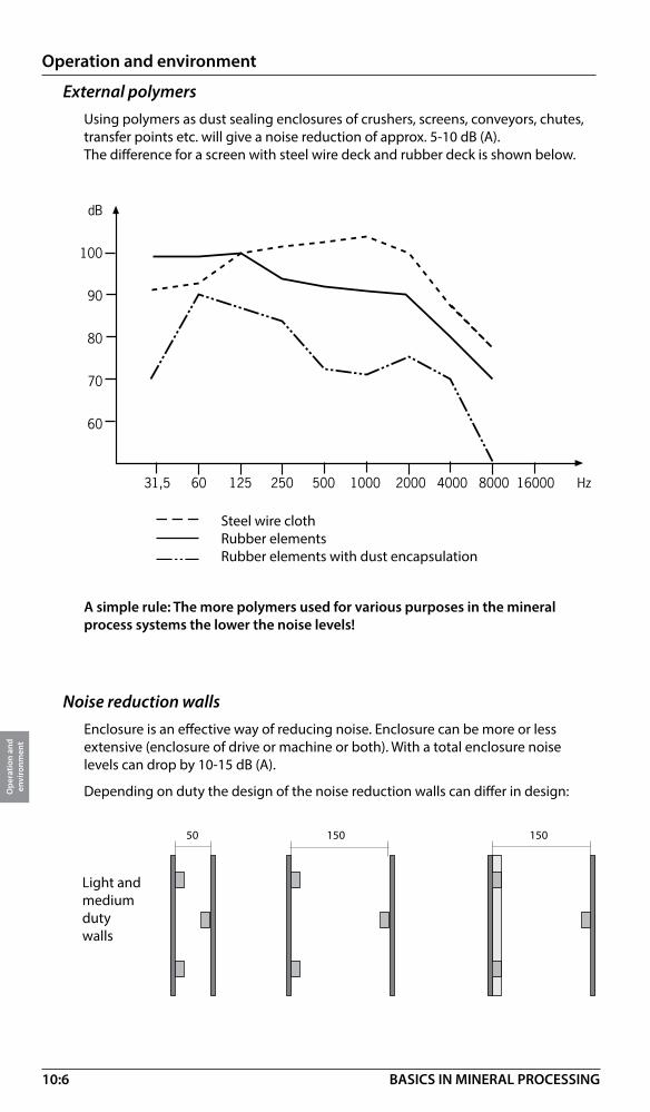
10:6
Operation and environment
Ope
ratio
n an
d en
viro
nmen
t
BASICS IN MINERAL PROCESSING
External polymersUsing polymers as dust sealing enclosures of crushers, screens, conveyors, chutes, transfer points etc. will give a noise reduction of approx. 5-10 dB (A). The difference for a screen with steel wire deck and rubber deck is shown below.
A simple rule: The more polymers used for various purposes in the mineral process systems the lower the noise levels!
Noise reduction wallsEnclosure is an effective way of reducing noise. Enclosure can be more or less extensive (enclosure of drive or machine or both). With a total enclosure noise levels can drop by 10-15 dB (A).
Depending on duty the design of the noise reduction walls can differ in design:
���� �������������������������������������������������� ��������������������
��
���
��
��
��
��
Steel wire clothRubber elementsRubber elements with dust encapsulation
50 150 150
Light and medium duty walls

10:7
Operation and environment
Ope
ratio
n an
d en
viro
nmen
t
BASICS IN MINERAL PROCESSING
Heavy duty crusher wall , cross section
Plate 1,2 mm
RHS vert.80x40x3 mm
Support
Weld
Beam200” 75” 8,5”
Service platform, not moving
Plate 1 mm
120-rail vertical
Absorbent 100 mm
Wood spacer 19 mm
Heavy rubber 5,2 mm
120-rail horizontal
Superior crusher112 DbA
Ear protectionWhen working in environments with continuous and high noise levels it is important to use ear protection all the time. Also at sound levels of 75-80 dB (A) it is to be recommended to use ear protection even if recommendation says something else. Reason is that long exposure also at these levels can cause impairment of hearing.
Good rules about ear protection:
• Take some “noise breaks” now and then
• Go for regular hearing tests
• Check your ear protection equipment at certain intervals

11:1
Process systems
Proc
ess
syst
em
BASICS IN MINERAL PROCESSING
Process system – IntroductionA machine working in a mineral process flow cannot perform better than the process environment will allow it to.
Parameters like type, size and amount of feed, % solids in slurries, additives, discharge conditions etc. will always guide equipment performance and operation economy.
There is a strong trend amongst both suppliers and users to work in terms of systems, meaning solutions to various operation problems more than installing equipment. This will effectively increase the operation values as presented in section 2:9
Examples covering systems levels and system modules are shown in this section.
Complete systems
Process systems
Product systems
Products
Mineral concentrate production
Comminution circuits
Crushing Grinding Filtration
Ad
ded
oper
atio
n va
lues
Separation circuits
Separation Thickening
Crushers Grinding mills FiltersSeparators Thickeners
Complete systems
Process systems
Product systems
Products
Aggregate production
Crushing Screening Conveying
Crushers Screens Conveyors Adde
d op
erat
ion
valu
es
Crushing and screening circuits
System levels in rock processing (Quarrying)
System levels in ore / Minerals processing
Dewatering circuits

11:2
Process systems
Proc
ess
syst
em
BASICS IN MINERAL PROCESSING
System modules – Sand and gravelSand and gravel module Sand and gravel module
Screening
Washing (Aquamator)
Washing (Log washer)
Fines
To sand module
To slurry handling
Coarse
Medium coarse
Washing (Aquamator)
Classifiying
Sandtrap
Slurry module
4:2
5:1
5:1
5:1
4:9
Water
Primary crushing module Intermediate crushing module
From rock front
Feeding
Crushing
Scalping
Closed 1
Screening
Crushing II, III or IV
Screening
Closed II
Open
Final products module Slurry handling module
Washing
To slurry circuit
Product screening
Classification
Sedimen- tation
Filtration
Sand
Recycled process water
= option or alternative
= referring to actual chapters and pages7:5
3:3
4:2
4:2
3:8
5:1
4:2
4:9
6:2
6:29
System modules – AggregatesA good way to understand and work with process systems is to use system modules in various combinations.
7:8

11:3
Process systems
Proc
ess
syst
em
BASICS IN MINERAL PROCESSING
Sedimentation
Dewatering
Drying
Sedimentation Primary
separation
Secondaryseparaton
Finalseparation
Optional
Tailingsdisposal
Wet Concentrate
Wet Tailings
Tailingsdry
Primarygrinding
Secondarygrinding Classi�cation
Tertiarygrinding
ROMPrimarycrushing
Secondary crushing Screening
Options
GrindingScreening
System modules – Ore and minerals
Crushing module
Grinding module
Enrichment module Upgrading module
4:2 3:8 4:2
3:31 3:31 4:9 3:31
5:5
5:5
5:5
6:2 6:2
6:25
6:57
Dry conc. Dry tailings Conc.
= option or alternative
= referring to actual chapters and pages7:5
3:6

11:4
Process systems
Proc
ess
syst
em
BASICS IN MINERAL PROCESSING
���������������
��������������
��������
���������������
������������
�������
����� ������
�������������
�������������
����
�����
�������
������ ����
������������
���������� �������������
Process system – Railway ballast
Process systems – Asphalt / Concrete ballast
Primary crushing module Secondary crushing module
Primary crushing module
���������������
��������������
����� ���������������
�����
�������������
������������������
����������
�������
�������
������������������
����������
���������
����������������
��������
Primary crushing module Secondary crushing module
Tertiary crushing module
Final products module
7:8 3:6 4:2 3:8 4:2
5:2 5:3
7:8 3:6 4:2 3:8 4:2
4:2 4:2
= option or alternative
= referring to actual chapters and pages7:5
Sedimentation
Dewatering
Drying
Sedimentation Primary
separation
Secondaryseparaton
Finalseparation
Optional
Tailingsdisposal
Wet Concentrate
Wet Tailings
Tailingsdry
Primarygrinding
Secondarygrinding Classi�cation
Tertiarygrinding
ROM Primarycrushing
Secondary crushing Screening
Optional
Screening
Optional
Optional
3:0

11:5
Process systems
Proc
ess
syst
em
BASICS IN MINERAL PROCESSING
������������������
����� �����������
��������� ����������� ���
����� ������� ���
������������
���������
�� ���������������
�������
�� ������������������������
����������
�����������
��������������
����������������������
���� ������������� ����������������������� �����������������
�������
����� ��
���������
�����������
����������
���������������
��������
���������������
����
�������
���� ��������
�����������
���������
����������������
�� �������������������
������� �����
��������������������
������� �������
�����������
Process system – Ferrous ore (hosting apatite)
Process system – Base metal ore
3:3 3:8 4:2 3:31 3:31 4:9
5:27
5:8
6:2
6:33
5:32
5:8
6:2
6:33
6:2
6:14 6:33
6:63
����������������
������
���������������
�������������������
������
���������
����������������������
���������
������������
������������������
��������
��������������
����������������
������
���������������
�������������������
���������
���������������
�������������
��������� �������
������������
�� ����������
�� ����������
������
���������������
������
���������������
�� ����������
��������������� ���������
�� ����������
������
�����������������
���� ����������
�������� ����������� ���
���� ������� ���
�������������
��������������
���� ������������� ����������������������� ��������� ������
��������
�������
= option or alternative
7:5= referring to actual chapters and pages
3:3 3:8 4:2 3:31 3:31 4:9
5:8
3:31
6:14
6:33
5:8
5:8
3:31
6:3
6:33
5:8
5:8
3:31
6:3
6:3
5:8
6:33
Sedimentation
Dewatering
Drying
Sedimentation Primary
separation
Secondaryseparaton
Finalseparation
Optional
Tailingsdisposal
Wet Concentrate
Wet Tailings
Tailingsdry
Primarygrinding
Secondarygrinding Classi�cation
Tertiarygrinding
ROM Primarycrushing
Secondary crushing Screening
Optional
ScreeningPrimary crushing
3:6Screening Secondary
crushing Screening
Gyr. jaw Cone
3:3 3:8 4:2
Sedimentation
Dewatering
Drying
Sedimentation Primary
separation
Secondaryseparaton
Finalseparation
Optional
Tailingsdisposal
Wet Concentrate
Wet Tailings
Tailingsdry
Primarygrinding
Secondarygrinding Classi�cation
Tertiarygrinding
ROM Primarycrushing
Secondary crushing Screening
Optional
Screening4:2
Primary crushing
3:6
Screening Secondary crushing
Screening
Gyr. jaw Cone
4:2 3:8 4:2
3:8 4:2
Optional
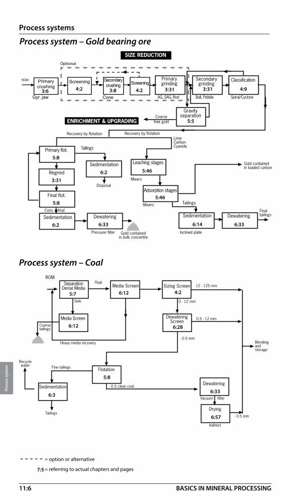
11:6
Process systems
Proc
ess
syst
em
BASICS IN MINERAL PROCESSING
Process system – Gold bearing ore
Process system – Coal
����������������������
�����������������������
���������
��������������������
�����������
������
�����������
������
��������
�������������
��������������
����������
��������
��������
������������������������������
��������������
������������
������������
�������������������������������
���������������
�����������������
������������ ����������
��������������������
�������������
������
����������������
��������������
�����������������
��������� �������������
�����������������
��������������
��������������
���� ��������� �� ��������������������� �����������������
�������
��������
3:3 3:8 4:2 3:31 3:31 4:9
5:8
3:31
5:8
6:2
6:2
6:33
5:46
5:46
6:336:14
5:5
�������������
����������� ������������ ����� �������
��������� ������
������������
��������
����
����� �������� �
���������
�����
�����������
�����������
���������������
���������
��������
��������
��������
��������������
����
����������� �
�����������������
�������������
���������� �
����� �
�����������
= option or alternative
= referring to actual chapters and pages7:5
5:7 4:2
6:28
6:3
5:8
6:33
6:57
3:3 3:8 4:2
Sedimentation
Dewatering
Drying
Sedimentation Primary
separation
Secondaryseparaton
Finalseparation
Optional
Tailingsdisposal
Wet Concentrate
Wet Tailings
Tailingsdry
Primarygrinding
Secondarygrinding Classi�cation
Tertiarygrinding
ROM Primarycrushing
Secondary crushing Screening
Optional
Screening
4:24:2Primary crushing
3:6
Screening Screening
Gyr. jaw
Sedimentation
Dewatering
Drying
Sedimentation Primary
separation
Secondaryseparaton
Finalseparation
Optional
Tailingsdisposal
Wet Concentrate
Wet Tailings
Tailingsdry
Primarygrinding
Secondarygrinding Classi�cation
Tertiarygrinding
ROM Primarycrushing
Secondary crushing Screening
Optional
Screening
Optional
6:12
6:12
Cone
Secondarycrushing
3:8

11:7
Process systems
Proc
ess
syst
em
BASICS IN MINERAL PROCESSING
����������
���������������
�����������������
��������� ������� ���������
�����������������
��������������
����������������������
���� �� �����������������������
�������
������
����������
��������������������
��������������������
������������������
��������
����������
�����
�������������
���������� ������������
����������������������������
������������
�����
����������
����������������
�����������������������
Process system – Industrial mineral fillers
Process system – Glass sand
��� ���������������
����� �����������
��������� ���� ��� ���������
��������
���� ����������
���� ����������
������������
������������������
���������
��������������
����������������������
���� ��������������� �������������
��������������
��
����������
������������
�������
����������������
������������
��������������
�� ����������
�� �������
��������
��������
��������� ������������������
�������
3:3 3:314:2
3:31
4:9
3:31
4:9
5:20
4:9
5:32 5:8
6:2
6:43Tube press
= option or alternative
= referring to actual chapters and pages7:5
3:3 3:8 3:313:2 4:9
4:10 5:2 5:324:10 5:8
6:21
6:3
Sedimentation
Dewatering
Drying
Sedimentation Primary
separation
Secondaryseparaton
Finalseparation
Optional
Tailingsdisposal
Wet Concentrate
Wet Tailings
Tailingsdry
Primarygrinding
Secondarygrinding Classi�cation
Tertiarygrinding
ROM Primarycrushing
Secondary crushing Screening
Optional
Screening
4:24:2
Primary crushing
3:6
Screening Secondary crushing
Screening
Gyr. jaw3:8
Cone
3:3 4:2
Sedimentation
Dewatering
Drying
Sedimentation Primary
separation
Secondaryseparaton
Finalseparation
Optional
Tailingsdisposal
Wet Concentrate
Wet Tailings
Tailingsdry
Primarygrinding
Secondarygrinding Classi�cation
Tertiarygrinding
ROM Primarycrushing
Secondary crushing Screening
Optional
Screening
4:24:2
Primary crushing
3:6
Screening Secondary crushing
Screening3:8
ConeGyr. jaw
Silica rock
Silica sand
Tailings disposal

11:8
Process systems
Proc
ess
syst
em
BASICS IN MINERAL PROCESSING
�������� ������ ����������������
���������������� �����������
��������� �������
������
�������������
����
����
����
���������
��
��������������
�����������
������� �������
�������
�������������
��������������
�������
������ �����
������ ����������������������
�������������
���������������������������������������
Process system – Diamonds (Kimberlite)
Process system – Kaolin
�������������������
���� ����� ������������������������� ������� ���������
�� ������ �� ����������������������� ��� ������ ����������������� �
��
���������������
���������
��������
����������
������������� �
������
� ����������������������� �������������
������������� �
�� ���� � ������������������
������������ �������
������������ ����� ���
����������
�������������������
������
= option or alternative
= referring to actual chapters and pages7:5
3:6 5:2 3:84:2
5:7 5:5 5:7
6:57
5:20
5:7
3:23
5:2
4:11 4:10 6:4
5:8 3:12
6:43
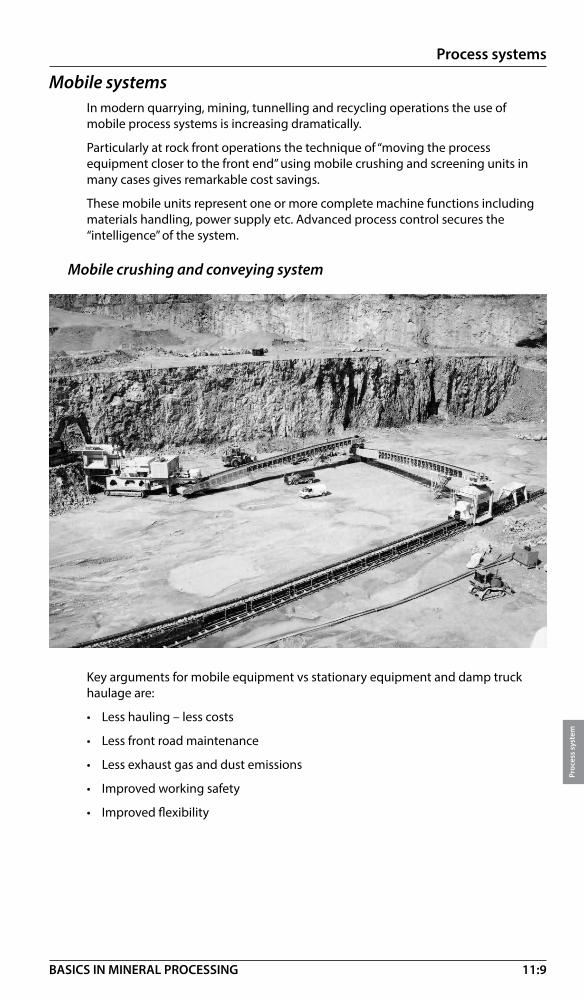
11:9
Process systems
Proc
ess
syst
em
BASICS IN MINERAL PROCESSING
Mobile systemsIn modern quarrying, mining, tunnelling and recycling operations the use of mobile process systems is increasing dramatically.
Particularly at rock front operations the technique of “moving the process equipment closer to the front end” using mobile crushing and screening units in many cases gives remarkable cost savings.
These mobile units represent one or more complete machine functions including materials handling, power supply etc. Advanced process control secures the “intelligence” of the system.
Mobile crushing and conveying system
Key arguments for mobile equipment vs stationary equipment and damp truck haulage are:
• Less hauling – less costs
• Less front road maintenance
• Less exhaust gas and dust emissions
• Improved working safety
• Improved flexibility

11:10
Process systems
Proc
ess
syst
em
BASICS IN MINERAL PROCESSING
Primary jaw crusher + Grizzly (typical)
Max feed/product size Capacity H/W/L Weight Type* mm (inch) tph m (ft) ton
LT110 670 / 250 (26/10) 700 4.4/3.0/17.4 (14.5/9.1/57.0) 60
LT125 800 / 300 (31/12) 800 5.7/4.0/15.8(18.6/15.2/51.1) 86
LT140 900 / 350 (35/14) 1200 6.3/4.3/16.4(20.8/14.1/53.1) 110
LT160 1040/ 400 (41/16) 2000 7.6/5.9/20.2(25.0/19.3/66.7) 220
*LT110 refers to Jaw crusher type C110, LT125 to Jaw crusher type C125 etc. see further section 3.
Primary impact crusher + Grizzly (typical)
Max feed/product size Capacity H/W/L WeightType* mm (inch) thp m (ft) ton
LT1415 1000/200 (40/8) 800 5.4/4.0/15.8 (17.7/13.1/51.1) 73
LT1620 1300/200 (52/8) 1200 6.5/4.8/18.5 (21.3/15.7/60.7) 170 *LT 1415 refers to Impact crusher type NP1415, LT 1620 to Impact crusher type NP1620 etc. see
further section 3.
Technical data sheet

11:11
Process systems
Proc
ess
syst
em
BASICS IN MINERAL PROCESSING
Metso simulation toolsBruno™ is a steady state simulation tool for the design and evaluation of crushing and screening plants. It is easy-to-use and the designer can quickly evaluate flowsheet options, select appropriate Metso equipment and forecast product quality and overall instantaneous system productivity.
For more information and/or to acquire a copy of the Bruno software, please contact your local Metso sales office.
Consulting businessTechnology development
Metso offers a global consulting service focused on simulation and automation.
In the area of Simulation Metso has a unique dynamic population balance modeling and simulation tool – Metso ProSim™ - which can be used to analyze, optimize and design mineral processing circuits. In addition to the usual suite of unit operation models, Metso ProSim™ utilizes multi-component structure and also allows for the inclusion of maintenance outages – planned and unplanned – moving toward the virtual plant. Metso also has a world-class multi physics simulation capability that allows for mircoscale analysis, design and optimization of components of process equipment, looking at productivity, product quality, wear and potential failure modes. This work involves the use of DEM, CFD, SPH, DGB, and other complex solution methodologies, requiring super computing platforms to deliver timely results. Finally, as part of the automation work (OCS© – 4D), Metso provides dynamic simulation capabilities that can be used to help design resilient process control solutions, develop custom advanced control strategies, and for training plant operators on new circuits.
In the area of Automation, Metso offers comprehensive control systems integration services which can include full electrical and instrumentation capabilities. In addition, process audits and training programs centered around regulatory automation needs are also part of the scope of services. Metso Computer Based Training (CBT) is also available to train plant operators on all aspects of the operation of comminution and/or flotation circuits Metso is also a leader in the field of Advanced Process Control (OCS©: model-based expert control) and Advanced Sensing (Visio™: machine vision, Audio™: machine acoustics), and is moving quickly into the related fields of Abnormal Situation Management and real-time data and image mining.
The objective of the Technology Development consulting activities is to identify and implement cost effective ways to improve plant productivity and lower unit costs, while respecting and enhancing the operational integrity and safety requirements of a plant.

11:12
Process systems
Proc
ess
syst
em
BASICS IN MINERAL PROCESSING
Mining Comminution Process DewateringFlotation
Leaching
Total process integration and optimization
Support during
commis-sioning
Continuous improve-
ment
Laboratory services Products
GREENFIELD
EXISTING OPERATIONS
Process technology and innovationProcess integration and optimization, is the development of integrated operating and control strategies from the mine to the plant that maximise throughput, minimise the overall cost per tonne and maximise profitability.
We offer consulting, laboratory and pilot plant services, and have developed supply and support for a range of products that have been designed to enhance the operation of mineral processes. Significant increases in throughput (5 to 30%) and metal recovery, cost and energy reduction, as well as overall process efficiency increases (from the mine to the plant) have been achieved at a number of operations worldwide.
Our particular focus is providing the industry with total process integration and optimization including optimization of the mining (drill and blast), comminution, flotation and dewatering processes for both Greenfield and existing operations. The main objectives are to reduce operating costs, increase production rates and improve overall process, energy and water efficiency.
For more information on Metso’s technology consulting businesses, please contact your local Metso sales office.
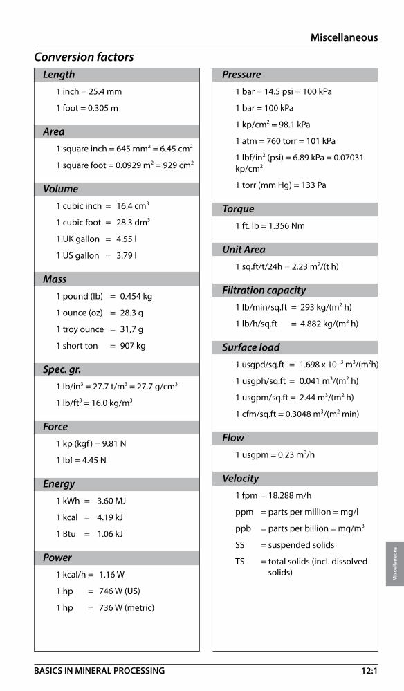
12:1
Miscellaneous
Mis
cella
neou
s
BASICS IN MINERAL PROCESSING
Conversion factorsLength
1 inch = 25.4 mm
1 foot = 0.305 m
Area1 square inch = 645 mm2 = 6.45 cm2
1 square foot = 0.0929 m2 = 929 cm2
Volume1 cubic inch = 16.4 cm3
1 cubic foot = 28.3 dm3
1 UK gallon = 4.55 l
1 US gallon = 3.79 l
Mass1 pound (lb) = 0.454 kg
1 ounce (oz) = 28.3 g
1 troy ounce = 31,7 g
1 short ton = 907 kg
Spec. gr.1 lb/in3 = 27.7 t/m3 = 27.7 g/cm3
1 lb/ft3 = 16.0 kg/m3
Force1 kp (kgf ) = 9.81 N
1 lbf = 4.45 N
Energy1 kWh = 3.60 MJ
1 kcal = 4.19 kJ
1 Btu = 1.06 kJ
Power1 kcal/h = 1.16 W
1 hp = 746 W (US)
1 hp = 736 W (metric)
Pressure1 bar = 14.5 psi = 100 kPa
1 bar = 100 kPa
1 kp/cm2 = 98.1 kPa
1 atm = 760 torr = 101 kPa
1 lbf/in2 (psi) = 6.89 kPa = 0.07031 kp/cm2
1 torr (mm Hg) = 133 Pa
Torque1 ft. lb = 1.356 Nm
Unit Area1 sq.ft/t/24h = 2.23 m2/(t h)
Filtration capacity1 lb/min/sq.ft = 293 kg/(m2 h)
1 lb/h/sq.ft = 4.882 kg/(m2 h)
Surface load1 usgpd/sq.ft = 1.698 x 10 - 3 m3/(m2h)
1 usgph/sq.ft = 0.041 m3/(m2 h)
1 usgpm/sq.ft = 2.44 m3/(m2 h)
1 cfm/sq.ft = 0.3048 m3/(m2 min)
Flow1 usgpm = 0.23 m3/h
Velocity1 fpm = 18.288 m/h
ppm = parts per million = mg/l
ppb = parts per billion = mg/m3
SS = suspended solids
TS = total solids (incl. dissolved solids)

12:2
Miscellaneous
Mis
cella
neou
s
BASICS IN MINERAL PROCESSING
Tyler standard scale
mesh micron mesh micron mesh micron 21/2 8 000 14 1 180 80 180 3 6 700 16 1 000 100 150 31/2 5 600 20 850 115 125 4 4 750 24 710 150 106 5 4 000 28 600 170 90 6 3 350 32 500 200 75 7 2 800 35 425 250 63 8 2 360 42 355 270 53 9 2 000 48 300 325 45 10 1 700 60 250 400 38 12 1 400 65 212 500 25
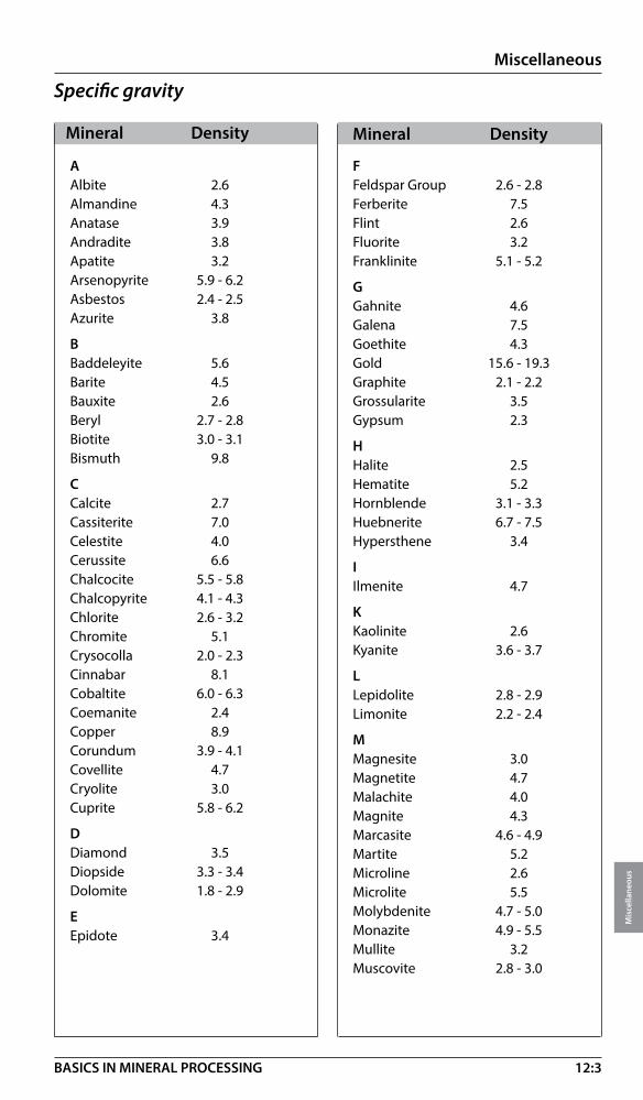
12:3
Miscellaneous
Mis
cella
neou
s
BASICS IN MINERAL PROCESSING
Specific gravity
Mineral Density Mineral Density
AAlbite 2.6Almandine 4.3Anatase 3.9Andradite 3.8Apatite 3.2Arsenopyrite 5.9 - 6.2Asbestos 2.4 - 2.5Azurite 3.8
BBaddeleyite 5.6Barite 4.5Bauxite 2.6Beryl 2.7 - 2.8Biotite 3.0 - 3.1Bismuth 9.8
CCalcite 2.7Cassiterite 7.0Celestite 4.0Cerussite 6.6Chalcocite 5.5 - 5.8Chalcopyrite 4.1 - 4.3Chlorite 2.6 - 3.2Chromite 5.1Crysocolla 2.0 - 2.3Cinnabar 8.1Cobaltite 6.0 - 6.3Coemanite 2.4Copper 8.9Corundum 3.9 - 4.1Covellite 4.7Cryolite 3.0Cuprite 5.8 - 6.2
DDiamond 3.5Diopside 3.3 - 3.4Dolomite 1.8 - 2.9
EEpidote 3.4
FFeldspar Group 2.6 - 2.8Ferberite 7.5Flint 2.6Fluorite 3.2Franklinite 5.1 - 5.2
GGahnite 4.6Galena 7.5Goethite 4.3Gold 15.6 - 19.3Graphite 2.1 - 2.2Grossularite 3.5Gypsum 2.3
HHalite 2.5Hematite 5.2Hornblende 3.1 - 3.3Huebnerite 6.7 - 7.5Hypersthene 3.4
IIlmenite 4.7
KKaolinite 2.6Kyanite 3.6 - 3.7
LLepidolite 2.8 - 2.9Limonite 2.2 - 2.4
MMagnesite 3.0Magnetite 4.7Malachite 4.0Magnite 4.3Marcasite 4.6 - 4.9Martite 5.2Microline 2.6Microlite 5.5Molybdenite 4.7 - 5.0Monazite 4.9 - 5.5Mullite 3.2Muscovite 2.8 - 3.0

12:4
Miscellaneous
Mis
cella
neou
s
BASICS IN MINERAL PROCESSING
N
Nepheline Syenite 2.6Niccolite 7.6 - 7.8
O
Olivine 3.3 - 3.5Orpiment 3.4 - 3.5Orthoclase 2.5 - 2.6
P
Petalite 2.4Platinum 14.0 - 21.5Pyrite 5.0Pyrochlore 4.2 - 4.4Pyrolusite 4.7 - 5.0Pyroxene 3.1 - 3.6Pyrrhotite 4.6 - 4.7
Q
Quartz 2.7
R
Realgar 3.6Rhodochrosite 3.7Rhodonite 3.6 - 3.7Rutile 4.2 - 4.3
S
Scheelite 6.1Serpentine 2.5 - 2.7Siderite 3.9Sillimanite 3.2Silver 10.1 - 11.1Smithsonite 4.1 - 4.5Sphalerite 3.9 - 4.0Sphene 3.3 - 8.6
Spinel 3.6Spodumene 3.1 - 3.2Stannite 4.3 - 4.5Stibnite (Antimonite) 4.6Sulphur 2.1Sylvite 2.0
T
Talc 2.7 - 2.8Tantalite 5.2 - 8.2Tetrahedrite 5.0Thorite 4.5 - 5.4Topaz 3.5 - 3.6Tourmaline 2.9 - 3.2
U
Uraninite 11.0
V
Vermiculite 2.4 - 2.7
W
Wolframite 6.7 - 7.5Wollastonite 2.8 - 2.9
Z
Zeolite 2.0 - 2.5Zincite 5.7Zircon 4.7
Other solids of varying composition:
Slag 1.5 - 4Soil 1.5 - 2.8Ash (fly) 1.5 - 3.5Ash (bottom) 1.5 - 3Wet scrubber effluent 2 - 5Mill scale 4.9 - 5.2
Mineral Density Mineral Density

12:5
Miscellaneous
Mis
cella
neou
s
BASICS IN MINERAL PROCESSING
Water and solids – Pulp density data (metric)A = Solids by weight [%] B = Pulp density [ton/m3]C = Pulp volume [m3/ton solids]
Density of solids: 1.4 Density of solids: 1.8 A B C A B C A B C A B C 1 1.003 99.714 41 1.133 2.153 1 1.004 99.556 41 1.223 1.995 2 1.006 49.714 42 1.136 2.095 2 1.009 49.556 42 1.230 1.937 3 1.009 33.048 43 1.140 2.040 3 1.014 32.889 43 1.236 1.881 4 1.012 24.714 44 1.144 1.987 4 1.018 24.556 44 1.243 1.828 5 1.014 19.714 45 1.148 1.937 5 1.023 19.556 45 1.250 1.778 6 1.017 16.381 46 1.151 1.888 6 1.027 16.222 46 1.257 1.729 7 1.020 14.000 47 1.155 1.842 7 1.032 13.841 47 1.264 1.683 8 1.023 12.214 48 1.159 1.798 8 1.037 12.056 48 1.271 1.639 9 1.026 10.825 49 1.163 1.755 9 1.042 10.667 49 1.278 1.596 10 1.029 9.714 50 1.167 1.714 10 1.047 9.556 50 1.286 1.556 11 1.032 8.805 51 1.171 1.675 11 1.051 8.646 51 1.293 1.516 12 1.036 8.048 52 1.174 1.637 12 1.056 7.889 52 1.301 1.479 13 1.039 7.407 53 1.178 1.601 13 1.061 7.248 53 1.308 1.442 14 1.042 6.857 54 1.182 1.566 14 1.066 6.698 54 1.316 1.407 15 1.045 6.381 55 1.186 1.532 15 1.071 6.222 55 1.324 1.374 16 1.048 5.964 56 1.190 1.500 16 1.077 5.806 56 1.331 1.341 17 1.051 5.597 57 1.195 1.469 17 1.082 5.438 57 1.339 1.310 18 1.054 5.270 58 1.199 1.438 18 1.087 5.111 58 1.347 1.280 19 1.057 4.977 59 1.203 1.409 19 1.092 4.819 59 1.355 1.250 20 1.061 4.714 60 1.207 1.381 20 1.098 4.556 60 1.364 1.222 21 1.064 4.476 61 1.211 1.354 21 1.103 4.317 61 1.372 1.195 22 1.067 4.260 62 1.215 1.327 22 1.108 4.101 62 1.380 1.168 23 1.070 4.062 63 1.220 1.302 23 1.114 3.903 63 1.389 1.143 24 1.074 3.881 64 1.224 1.277 24 1.119 3.722 64 1.398 1.118 25 1.077 3.714 65 1.228 1.253 25 1.125 3.556 65 1.406 1.094 26 1.080 3.560 66 1.232 1.229 26 1.131 3.402 66 1.415 1.071 27 1.084 3.418 67 1.237 1.207 27 1.136 3.259 67 1.424 1.048 28 1.087 3.286 68 1.241 1.185 28 1.142 3.127 68 1.433 1.026 29 1.090 3.163 69 1.246 1.164 29 1.148 3.004 69 1.442 1.005 30 1.094 3.048 70 1.250 1.143 30 1.154 2.889 70 1.452 0.984 31 1.097 2.940 71 1.254 1.123 31 1.160 2.781 71 1.461 0.964 32 1.101 2.839 72 1.259 1.103 32 1.166 2.681 72 1.471 0.944 33 1.104 2.745 73 1.264 1.084 33 1.172 2.586 73 1.480 0.925 34 1.108 2.655 74 1.268 1.066 34 1.178 2.497 74 1.490 0.907 35 1.111 2.571 75 1.273 1.048 35 1.184 2.413 75 1.500 0.889 36 1.115 2.492 76 1.277 1.030 36 1.190 2.333 76 1.510 0.871 37 1.118 2.417 77 1.282 1.013 37 1.197 2.258 77 1.520 0.854 38 1.122 2.346 78 1.287 0.996 38 1.203 2.187 78 1.531 0.838 39 1.125 2.278 79 1.292 0.980 39 1.210 2.120 79 1.541 0.821 40 1.129 2.214 80 1.296 0.964 40 1.216 2.056 80 1.552 0.806

12:6
Miscellaneous
Mis
cella
neou
s
BASICS IN MINERAL PROCESSING
Water and solids – Pulp density data (US)A = Solids by weight [%] B = Pulp densityC = Pulp volume [USG/ston solids]
Density of solids: 1.4 Density of solids: 1.8 A B C A B C A B C A B C 1 1.003 23897 41 1.133 516 1 1.004 23859 41 1.223 478 2 1.006 11914 42 1.136 502 2 1.009 11876 42 1.230 464 3 1.009 7920 43 1.140 489 3 1.014 7882 43 1.236 451 4 1.012 5923 44 1.144 476 4 1.018 5885 44 1.243 438 5 1.014 4725 45 1.148 464 5 1.023 4687 45 1.250 426 6 1.017 3926 46 1.151 452 6 1.027 3888 46 1.257 414 7 1.020 3355 47 1.155 441 7 1.032 3317 47 1.264 403 8 1.023 2927 48 1.159 431 8 1.037 2889 48 1.271 393 9 1.026 2594 49 1.163 421 9 1.042 2556 49 1.278 382 10 1.029 2328 50 1.167 411 10 1.047 2290 50 1.286 373 11 1.032 2110 51 1.171 401 11 1.051 2072 51 1.293 363 12 1.036 1929 52 1.174 392 12 1.056 1891 52 1.301 354 13 1.039 1775 53 1.178 384 13 1.061 1737 53 1.308 346 14 1.042 1643 54 1.182 375 14 1.066 1605 54 1.316 337 15 1.045 1529 55 1.186 367 15 1.071 1491 55 1.324 329 16 1.048 1429 56 1.190 359 16 1.077 1391 56 1.331 321 17 1.051 1341 57 1.195 352 17 1.082 1303 57 1.339 314 18 1.054 1263 58 1.199 345 18 1.087 1225 58 1.347 307 19 1.057 1193 59 1.203 338 19 1.092 1155 59 1.355 300 20 1.061 1130 60 1.207 331 20 1.098 1092 60 1.364 293 21 1.064 1073 61 1.211 324 21 1.103 1035 61 1.372 286 22 1.067 1021 62 1.215 318 22 1.108 983 62 1.380 280 23 1.070 973 63 1.220 312 23 1.114 935 63 1.389 274 24 1.074 930 64 1.224 306 24 1.119 892 64 1.398 268 25 1.077 890 65 1.228 300 25 1.125 852 65 1.406 262 26 1.080 853 66 1.232 295 26 1.131 815 66 1.415 257 27 1.084 819 67 1.237 289 27 1.136 781 67 1.424 251 28 1.087 787 68 1.241 284 28 1.142 749 68 1.433 246 29 1.090 758 69 1.246 279 29 1.148 720 69 1.442 241 30 1.094 730 70 1.250 274 30 1.154 692 70 1.452 236 31 1.097 705 71 1.254 269 31 1.160 666 71 1.461 231 32 1.101 680 72 1.259 264 32 1.166 643 72 1.471 226 33 1.104 658 73 1.264 260 33 1.172 620 73 1.480 222 34 1.108 636 74 1.268 255 34 1.178 598 74 1.490 217 35 1.111 616 75 1.273 251 35 1.184 578 75 1.500 213 36 1.115 597 76 1.277 247 36 1.190 559 76 1.510 209 37 1.118 579 77 1.282 243 37 1.197 541 77 1.520 205 38 1.122 562 78 1.287 239 38 1.203 524 78 1.531 201 39 1.125 546 79 1.292 235 39 1.210 508 79 1.541 197 40 1.129 531 80 1.296 231 40 1.216 493 80 1.552 193

12:7
Miscellaneous
Mis
cella
neou
s
BASICS IN MINERAL PROCESSING
Water and solids – Pulp density data (metric)A = Solids by weight [%] B = Pulp density [ton/m3]C = Pulp volume [m3/ton solids]
Density of solids: 2.0 Density of solids: 2.6 A B C A B C A B C A B C 1 1.005 99.500 41 1.258 1.939 1 1.006 99.385 41 1.337 1.824 2 1.010 49.500 42 1.266 1.881 2 1.012 49.385 42 1.349 1.766 3 1.015 32.833 43 1.274 1.826 3 1.019 32.718 43 1.360 1.710 4 1.020 24.500 44 1.282 1.773 4 1.025 24.385 44 1.371 1.657 5 1.026 19.500 45 1.290 1.722 5 1.032 19.385 45 1.383 1.607 6 1.031 16.167 46 1.299 1.674 6 1.038 16.051 46 1.395 1.559 7 1.036 13.786 47 1.307 1.628 7 1.045 13.670 47 1.407 1.512 8 1.042 12.000 48 1.316 1.583 8 1.052 11.885 48 1.419 1.468 9 1.047 10.611 49 1.325 1.541 9 1.059 10.496 49 1.432 1.425 10 1.053 9.500 50 1.333 1.500 10 1.066 9.385 50 1.444 1.385 11 1.058 8.591 51 1.342 1.461 11 1.073 8.476 51 1.457 1.345 12 1.064 7.833 52 1.351 1.423 12 1.080 7.718 52 1.471 1.308 13 1.070 7.192 53 1.361 1.387 13 1.087 7.077 53 1.484 1.271 14 1.075 6.643 54 1.370 1.352 14 1.094 6.527 54 1.498 1.236 15 1.081 6.167 55 1.379 1.318 15 1.102 6.051 55 1.512 1.203 16 1.087 5.750 56 1.389 1.286 16 1.109 5.635 56 1.526 1.170 17 1.093 5.382 57 1.399 1.254 17 1.117 5.267 57 1.540 1.139 18 1.099 5.056 58 1.408 1.224 18 1.125 4.940 58 1.555 1.109 19 1.105 4.763 59 1.418 1.195 19 1.132 4.648 59 1.570 1.080 20 1.111 4.500 60 1.429 1.167 20 1.140 4.385 60 1.585 1.051 21 1.117 4.262 61 1.439 1.139 21 1.148 4.147 61 1.601 1.024 22 1.124 4.045 62 1.449 1.113 22 1.157 3.930 62 1.617 0.998 23 1.130 3.848 63 1.460 1.087 23 1.165 3.732 63 1.633 0.972 24 1.136 3.667 64 1.471 1.063 24 1.173 3.551 64 1.650 0.947 25 1.143 3.500 65 1.481 1.038 25 1.182 3.385 65 1.667 0.923 26 1.149 3.346 66 1.493 1.015 26 1.190 3.231 66 1.684 0.900 27 1.156 3.204 67 1.504 0.993 27 1.199 3.088 67 1.702 0.877 28 1.163 3.071 68 1.515 0.971 28 1.208 2.956 68 1.720 0.855 29 1.170 2.948 69 1.527 0.949 29 1.217 2.833 69 1.738 0.834 30 1.176 2.833 70 1.538 0.929 30 1.226 2.718 70 1.757 0.813 31 1.183 2.726 71 1.550 0.908 31 1.236 2.610 71 1.776 0.793 32 1.190 2.625 72 1.563 0.889 32 1.245 2.510 72 1.796 0.774 33 1.198 2.530 73 1.575 0.870 33 1.255 2.415 73 1.816 0.754 34 1.205 2.441 74 1.587 0.851 34 1.265 2.326 74 1.836 0.736 35 1.212 2.357 75 1.600 0.833 35 1.275 2.242 75 1.857 0.718 36 1.220 2.278 76 1.613 0.816 36 1.285 2.162 76 1.879 0.700 37 1.227 2.203 77 1.626 0.799 37 1.295 2.087 77 1.901 0.683 38 1.235 2.132 78 1.639 0.782 38 1.305 2.016 78 1.923 0.667 39 1.242 2.064 79 1.653 0.766 39 1.316 1.949 79 1.946 0.650 40 1.250 2.000 80 1.667 0.750 40 1.327 1.885 80 1.970 0.635
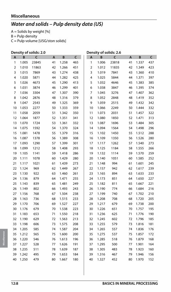
12:8
Miscellaneous
Mis
cella
neou
s
BASICS IN MINERAL PROCESSING
Water and solids – Pulp density data (US)A = Solids by weight [%] B = Pulp densityC = Pulp volume [USG/ston solids]
Density of solids: 2.0 Density of solids: 2.6 A B C A B C A B C A B C 1 1.005 23845 41 1.258 465 1 1.006 23818 41 1.337 437 2 1.010 11863 42 1.266 451 2 1.012 11835 42 1.349 423 3 1.015 7869 43 1.274 438 3 1.019 7841 43 1.360 410 4 1.020 5871 44 1.282 425 4 1.025 5844 44 1.371 397 5 1.026 4673 45 1.290 413 5 1.032 4646 45 1.383 385 6 1.031 3874 46 1.299 401 6 1.038 3847 46 1.395 374 7 1.036 3304 47 1.307 390 7 1.045 3276 47 1.407 362 8 1.042 2876 48 1.316 379 8 1.052 2848 48 1.419 352 9 1.047 2543 49 1.325 369 9 1.059 2515 49 1.432 342 10 1.053 2277 50 1.333 359 10 1.066 2249 50 1.444 332 11 1.058 2059 51 1.342 350 11 1.073 2031 51 1.457 322 12 1.064 1877 52 1.351 341 12 1.080 1850 52 1.471 313 13 1.070 1724 53 1.361 332 13 1.087 1696 53 1.484 305 14 1.075 1592 54 1.370 324 14 1.094 1564 54 1.498 296 15 1.081 1478 55 1.379 316 15 1.102 1450 55 1.512 288 16 1.087 1378 56 1.389 308 16 1.109 1350 56 1.526 280 17 1.093 1290 57 1.399 301 17 1.117 1262 57 1.540 273 18 1.099 1212 58 1.408 293 18 1.125 1184 58 1.555 266 19 1.105 1141 59 1.418 286 19 1.132 1114 59 1.570 259 20 1.111 1078 60 1.429 280 20 1.140 1051 60 1.585 252 21 1.117 1021 61 1.439 273 21 1.148 994 61 1.601 245 22 1.124 969 62 1.449 267 22 1.157 942 62 1.617 239 23 1.130 922 63 1.460 261 23 1.165 894 63 1.633 233 24 1.136 879 64 1.471 255 24 1.173 851 64 1.650 227 25 1.143 839 65 1.481 249 25 1.182 811 65 1.667 221 26 1.149 802 66 1.493 243 26 1.190 774 66 1.684 216 27 1.156 768 67 1.504 238 27 1.199 740 67 1.702 210 28 1.163 736 68 1.515 233 28 1.208 708 68 1.720 205 29 1.170 706 69 1.527 227 29 1.217 679 69 1.738 200 30 1.176 679 70 1.538 223 30 1.226 651 70 1.757 195 31 1.183 653 71 1.550 218 31 1.236 625 71 1.776 190 32 1.190 629 72 1.563 213 32 1.245 602 72 1.796 185 33 1.198 606 73 1.575 208 33 1.255 579 73 1.816 181 34 1.205 585 74 1.587 204 34 1.265 557 74 1.836 176 35 1.212 565 75 1.600 200 35 1.275 537 75 1.857 172 36 1.220 546 76 1.613 196 36 1.285 518 76 1.879 168 37 1.227 528 77 1.626 191 37 1.295 500 77 1.901 164 38 1.235 511 78 1.639 187 38 1.305 483 78 1.923 160 39 1.242 495 79 1.653 184 39 1.316 467 79 1.946 156 40 1.250 479 80 1.667 180 40 1.327 452 80 1.970 152

12:9
Miscellaneous
Mis
cella
neou
s
BASICS IN MINERAL PROCESSING
Water and solids – Pulp density data (metric)A = Solids by weight [%] B = Pulp density [ton/m3]C = Pulp volume [m3/ton solids]
Density of solids: 2.8 Density of solids: 3.0 A B C A B C A B C A B C 1 1.006 99.357 41 1.358 1.796 1 1.007 99.333 41 1.376 1.772 2 1.013 49.357 42 1.370 1.738 2 1.014 49.333 42 1.389 1.714 3 1.020 32.690 43 1.382 1.683 3 1.020 32.667 43 1.402 1.659 4 1.026 24.357 44 1.394 1.630 4 1.027 24.333 44 1.415 1.606 5 1.033 19.357 45 1.407 1.579 5 1.034 19.333 45 1.429 1.556 6 1.040 16.024 46 1.420 1.531 6 1.042 16.000 46 1.442 1.507 7 1.047 13.643 47 1.433 1.485 7 1.049 13.619 47 1.456 1.461 8 1.054 11.857 48 1.446 1.440 8 1.056 11.833 48 1.471 1.417 9 1.061 10.468 49 1.460 1.398 9 1.064 10.444 49 1.485 1.374 10 1.069 9.357 50 1.474 1.357 10 1.071 9.333 50 1.500 1.333 11 1.076 8.448 51 1.488 1.318 11 1.079 8.424 51 1.515 1.294 12 1.084 7.690 52 1.502 1.280 12 1.087 7.667 52 1.531 1.256 13 1.091 7.049 53 1.517 1.244 13 1.095 7.026 53 1.546 1.220 14 1.099 6.500 54 1.532 1.209 14 1.103 6.476 54 1.563 1.185 15 1.107 6.024 55 1.547 1.175 15 1.111 6.000 55 1.579 1.152 16 1.115 5.607 56 1.563 1.143 16 1.119 5.583 56 1.596 1.119 17 1.123 5.239 57 1.578 1.112 17 1.128 5.216 57 1.613 1.088 18 1.131 4.913 58 1.595 1.081 18 1.136 4.889 58 1.630 1.057 19 1.139 4.620 59 1.611 1.052 19 1.145 4.596 59 1.648 1.028 20 1.148 4.357 60 1.628 1.024 20 1.154 4.333 60 1.667 1.000 21 1.156 4.119 61 1.645 0.996 21 1.163 4.095 61 1.685 0.973 22 1.165 3.903 62 1.663 0.970 22 1.172 3.879 62 1.705 0.946 23 1.174 3.705 63 1.681 0.944 23 1.181 3.681 63 1.724 0.921 24 1.182 3.524 64 1.699 0.920 24 1.190 3.500 64 1.744 0.896 25 1.191 3.357 65 1.718 0.896 25 1.200 3.333 65 1.765 0.872 26 1.201 3.203 66 1.737 0.872 26 1.210 3.179 66 1.786 0.848 27 1.210 3.061 67 1.757 0.850 27 1.220 3.037 67 1.807 0.826 28 1.220 2.929 68 1.777 0.828 28 1.230 2.905 68 1.829 0.804 29 1.229 2.805 69 1.797 0.806 29 1.240 2.782 69 1.852 0.783 30 1.239 2.690 70 1.818 0.786 30 1.250 2.667 70 1.875 0.762 31 1.249 2.583 71 1.840 0.766 31 1.261 2.559 71 1.899 0.742 32 1.259 2.482 72 1.862 0.746 32 1.271 2.458 72 1.923 0.722 33 1.269 2.387 73 1.884 0.727 33 1.282 2.364 73 1.948 0.703 34 1.280 2.298 74 1.907 0.708 34 1.293 2.275 74 1.974 0.685 35 1.290 2.214 75 1.931 0.690 35 1.304 2.190 75 2.000 0.667 36 1.301 2.135 76 1.955 0.673 36 1.316 2.111 76 2.027 0.649 37 1.312 2.060 77 1.980 0.656 37 1.327 2.036 77 2.055 0.632 38 1.323 1.989 78 2.006 0.639 38 1.339 1.965 78 2.083 0.615 39 1.335 1.921 79 2.032 0.623 39 1.351 1.897 79 2.113 0.599 40 1.346 1.857 80 2.059 0.607 40 1.364 1.833 80 2.143 0.583
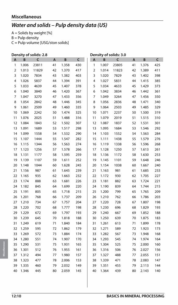
12:10
Miscellaneous
Mis
cella
neou
s
BASICS IN MINERAL PROCESSING
Water and solids – Pulp density data (US)A = Solids by weight [%] B = Pulp densityC = Pulp volume [USG/ston solids]
Density of solids: 2.8 Density of solids: 3.0 A B C A B C A B C A B C 1 1.006 23811 41 1.358 430 1 1.007 23805 41 1.376 425 2 1.013 11829 42 1.370 417 2 1.014 11823 42 1.389 411 3 1.020 7834 43 1.382 403 3 1.020 7829 43 1.402 398 4 1.026 5837 44 1.394 391 4 1.027 5831 44 1.415 385 5 1.033 4639 45 1.407 378 5 1.034 4633 45 1.429 373 6 1.040 3840 46 1.420 367 6 1.042 3834 46 1.442 361 7 1.047 3270 47 1.433 356 7 1.049 3264 47 1.456 350 8 1.054 2842 48 1.446 345 8 1.056 2836 48 1.471 340 9 1.061 2509 49 1.460 335 9 1.064 2503 49 1.485 329 10 1.069 2242 50 1.474 325 10 1.071 2237 50 1.500 319 11 1.076 2025 51 1.488 316 11 1.079 2019 51 1.515 310 12 1.084 1843 52 1.502 307 12 1.087 1837 52 1.531 301 13 1.091 1689 53 1.517 298 13 1.095 1684 53 1.546 292 14 1.099 1558 54 1.532 290 14 1.103 1552 54 1.563 284 15 1.107 1444 55 1.547 282 15 1.111 1438 55 1.579 276 16 1.115 1344 56 1.563 274 16 1.119 1338 56 1.596 268 17 1.123 1256 57 1.578 266 17 1.128 1250 57 1.613 261 18 1.131 1177 58 1.595 259 18 1.136 1172 58 1.630 253 19 1.139 1107 59 1.611 252 19 1.145 1101 59 1.648 246 20 1.148 1044 60 1.628 245 20 1.154 1038 60 1.667 240 21 1.156 987 61 1.645 239 21 1.163 981 61 1.685 233 22 1.165 935 62 1.663 232 22 1.172 930 62 1.705 227 23 1.174 888 63 1.681 226 23 1.181 882 63 1.724 221 24 1.182 845 64 1.699 220 24 1.190 839 64 1.744 215 25 1.191 805 65 1.718 215 25 1.200 799 65 1.765 209 26 1.201 768 66 1.737 209 26 1.210 762 66 1.786 203 27 1.210 734 67 1.757 204 27 1.220 728 67 1.807 198 28 1.220 702 68 1.777 198 28 1.230 696 68 1.829 193 29 1.229 672 69 1.797 193 29 1.240 667 69 1.852 188 30 1.239 645 70 1.818 188 30 1.250 639 70 1.875 183 31 1.249 619 71 1.840 184 31 1.261 613 71 1.899 178 32 1.259 595 72 1.862 179 32 1.271 589 72 1.923 173 33 1.269 572 73 1.884 174 33 1.282 567 73 1.948 168 34 1.280 551 74 1.907 170 34 1.293 545 74 1.974 164 35 1.290 531 75 1.931 165 35 1.304 525 75 2.000 160 36 1.301 512 76 1.955 161 36 1.316 506 76 2.027 156 37 1.312 494 77 1.980 157 37 1.327 488 77 2.055 151 38 1.323 477 78 2.006 153 38 1.339 471 78 2.083 147 39 1.335 460 79 2.032 149 39 1.351 455 79 2.113 144 40 1.346 445 80 2.059 145 40 1.364 439 80 2.143 140
12:11
Miscellaneous
Mis
cella
neou
s
BASICS IN MINERAL PROCESSING
Water and solids – Pulp density data (metric)A = Solids by weight [%] B = Pulp density [ton/m3]C = Pulp volume [m3/ton solids]
Density of solids: 3.2 Density of solids: 3.4 A B C A B C A B C A B C 1 1.007 99.313 41 1.393 1.752 1 1.007 99.294 41 1.407 1.733 2 1.014 49.313 42 1.406 1.693 2 1.014 49.294 42 1.421 1.675 3 1.021 32.646 43 1.420 1.638 3 1.022 32.627 43 1.436 1.620 4 1.028 24.313 44 1.434 1.585 4 1.029 24.294 44 1.451 1.567 5 1.036 19.313 45 1.448 1.535 5 1.037 19.294 45 1.466 1.516 6 1.043 15.979 46 1.463 1.486 6 1.044 15.961 46 1.481 1.468 7 1.051 13.598 47 1.477 1.440 7 1.052 13.580 47 1.496 1.422 8 1.058 11.813 48 1.493 1.396 8 1.060 11.794 48 1.512 1.377 9 1.066 10.424 49 1.508 1.353 9 1.068 10.405 49 1.529 1.335 10 1.074 9.313 50 1.524 1.313 10 1.076 9.294 50 1.545 1.294 11 1.082 8.403 51 1.540 1.273 11 1.084 8.385 51 1.563 1.255 12 1.090 7.646 52 1.556 1.236 12 1.093 7.627 52 1.580 1.217 13 1.098 7.005 53 1.573 1.199 13 1.101 6.986 53 1.598 1.181 14 1.107 6.455 54 1.590 1.164 14 1.110 6.437 54 1.616 1.146 15 1.115 5.979 55 1.608 1.131 15 1.118 5.961 55 1.635 1.112 16 1.124 5.563 56 1.626 1.098 16 1.127 5.544 56 1.654 1.080 17 1.132 5.195 57 1.644 1.067 17 1.136 5.176 57 1.673 1.049 18 1.141 4.868 58 1.663 1.037 18 1.146 4.850 58 1.693 1.018 19 1.150 4.576 59 1.682 1.007 19 1.155 4.557 59 1.714 0.989 20 1.159 4.313 60 1.702 0.979 20 1.164 4.294 60 1.735 0.961 21 1.169 4.074 61 1.722 0.952 21 1.174 4.056 61 1.756 0.933 22 1.178 3.858 62 1.743 0.925 22 1.184 3.840 62 1.778 0.907 23 1.188 3.660 63 1.764 0.900 23 1.194 3.642 63 1.801 0.881 24 1.198 3.479 64 1.786 0.875 24 1.204 3.461 64 1.824 0.857 25 1.208 3.313 65 1.808 0.851 25 1.214 3.294 65 1.848 0.833 26 1.218 3.159 66 1.831 0.828 26 1.225 3.140 66 1.872 0.809 27 1.228 3.016 67 1.854 0.805 27 1.235 2.998 67 1.897 0.787 28 1.238 2.884 68 1.878 0.783 28 1.246 2.866 68 1.923 0.765 29 1.249 2.761 69 1.902 0.762 29 1.257 2.742 69 1.950 0.743 30 1.260 2.646 70 1.928 0.741 30 1.269 2.627 70 1.977 0.723 31 1.271 2.538 71 1.954 0.721 31 1.280 2.520 71 2.005 0.703 32 1.282 2.438 72 1.980 0.701 32 1.292 2.419 72 2.033 0.683 33 1.293 2.343 73 2.008 0.682 33 1.304 2.324 73 2.063 0.664 34 1.305 2.254 74 2.036 0.664 34 1.316 2.235 74 2.094 0.645 35 1.317 2.170 75 2.065 0.646 35 1.328 2.151 75 2.125 0.627 36 1.329 2.090 76 2.094 0.628 36 1.341 2.072 76 2.157 0.610 37 1.341 2.015 77 2.125 0.611 37 1.354 1.997 77 2.191 0.593 38 1.354 1.944 78 2.156 0.595 38 1.367 1.926 78 2.225 0.576 39 1.366 1.877 79 2.189 0.578 39 1.380 1.858 79 2.261 0.560 40 1.379 1.813 80 2.222 0.563 40 1.393 1.794 80 2.297 0.544

12:12
Miscellaneous
Mis
cella
neou
s
BASICS IN MINERAL PROCESSING
Water and solids – Pulp density data (US)A = Solids by weight [%] B = Pulp densityC = Pulp volume [USG/ston solids]
Density of solids: 3.2 Density of solids: 3.4 A B C A B C A B C A B C 1 1.007 23801 41 1.393 420 1 1.007 23796 41 1.407 415 2 1.014 11818 42 1.406 406 2 1.014 11813 42 1.421 401 3 1.021 7824 43 1.420 393 3 1.022 7819 43 1.436 388 4 1.028 5827 44 1.434 380 4 1.029 5822 44 1.451 376 5 1.036 4628 45 1.448 368 5 1.037 4624 45 1.466 363 6 1.043 3829 46 1.463 356 6 1.044 3825 46 1.481 352 7 1.051 3259 47 1.477 345 7 1.052 3254 47 1.496 341 8 1.058 2831 48 1.493 335 8 1.060 2826 48 1.512 330 9 1.066 2498 49 1.508 324 9 1.068 2494 49 1.529 320 10 1.074 2232 50 1.524 315 10 1.076 2227 50 1.545 310 11 1.082 2014 51 1.540 305 11 1.084 2009 51 1.563 301 12 1.090 1832 52 1.556 296 12 1.093 1828 52 1.580 292 13 1.098 1679 53 1.573 287 13 1.101 1674 53 1.598 283 14 1.107 1547 54 1.590 279 14 1.110 1543 54 1.616 275 15 1.115 1433 55 1.608 271 15 1.118 1429 55 1.635 266 16 1.124 1333 56 1.626 263 16 1.127 1329 56 1.654 259 17 1.132 1245 57 1.644 256 17 1.136 1240 57 1.673 251 18 1.141 1167 58 1.663 249 18 1.146 1162 58 1.693 244 19 1.150 1097 59 1.682 241 19 1.155 1092 59 1.714 237 20 1.159 1034 60 1.702 235 20 1.164 1029 60 1.735 230 21 1.169 976 61 1.722 228 21 1.174 972 61 1.756 224 22 1.178 925 62 1.743 222 22 1.184 920 62 1.778 217 23 1.188 877 63 1.764 216 23 1.194 873 63 1.801 211 24 1.198 834 64 1.786 210 24 1.204 829 64 1.824 205 25 1.208 794 65 1.808 204 25 1.214 789 65 1.848 200 26 1.218 757 66 1.831 198 26 1.225 753 66 1.872 194 27 1.228 723 67 1.854 193 27 1.235 718 67 1.897 189 28 1.238 691 68 1.878 188 28 1.246 687 68 1.923 183 29 1.249 662 69 1.902 183 29 1.257 657 69 1.950 178 30 1.260 634 70 1.928 178 30 1.269 630 70 1.977 173 31 1.271 608 71 1.954 173 31 1.280 604 71 2.005 168 32 1.282 584 72 1.980 168 32 1.292 580 72 2.033 164 33 1.293 562 73 2.008 163 33 1.304 557 73 2.063 159 34 1.305 540 74 2.036 159 34 1.316 536 74 2.094 155 35 1.317 520 75 2.065 155 35 1.328 515 75 2.125 150 36 1.329 501 76 2.094 151 36 1.341 497 76 2.157 146 37 1.341 483 77 2.125 146 37 1.354 479 77 2.191 142 38 1.354 466 78 2.156 143 38 1.367 462 78 2.225 138 39 1.366 450 79 2.189 139 39 1.380 445 79 2.261 134 40 1.379 434 80 2.222 135 40 1.393 430 80 2.297 130

12:13
Miscellaneous
Mis
cella
neou
s
BASICS IN MINERAL PROCESSING
Water and solids – Pulp density data (metric)A = Solids by weight [%] B = Pulp density [ton/m3]C = Pulp volume [m3/ton solids]
Density of solids: 3.6 Density of solids: 3.8 A B C A B C A B C A B C 1 1.007 99.278 41 1.421 1.717 1 1.007 99.263 41 1.433 1.702 2 1.015 49.278 42 1.435 1.659 2 1.015 49.263 42 1.448 1.644 3 1.022 32.611 43 1.450 1.603 3 1.023 32.596 43 1.464 1.589 4 1.030 24.278 44 1.466 1.551 4 1.030 24.263 44 1.480 1.536 5 1.037 19.278 45 1.481 1.500 5 1.038 19.263 45 1.496 1.485 6 1.045 15.944 46 1.498 1.452 6 1.046 15.930 46 1.513 1.437 7 1.053 13.563 47 1.514 1.405 7 1.054 13.549 47 1.530 1.391 8 1.061 11.778 48 1.531 1.361 8 1.063 11.763 48 1.547 1.346 9 1.070 10.389 49 1.548 1.319 9 1.071 10.374 49 1.565 1.304 10 1.078 9.278 50 1.565 1.278 10 1.080 9.263 50 1.583 1.263 11 1.086 8.369 51 1.583 1.239 11 1.088 8.354 51 1.602 1.224 12 1.095 7.611 52 1.601 1.201 12 1.097 7.596 52 1.621 1.186 13 1.104 6.970 53 1.620 1.165 13 1.106 6.955 53 1.641 1.150 14 1.112 6.421 54 1.639 1.130 14 1.115 6.406 54 1.661 1.115 15 1.121 5.944 55 1.659 1.096 15 1.124 5.930 55 1.681 1.081 16 1.131 5.528 56 1.679 1.063 16 1.134 5.513 56 1.703 1.049 17 1.140 5.160 57 1.700 1.032 17 1.143 5.146 57 1.724 1.018 18 1.149 4.833 58 1.721 1.002 18 1.153 4.819 58 1.746 0.987 19 1.159 4.541 59 1.742 0.973 19 1.163 4.526 59 1.769 0.958 20 1.169 4.278 60 1.765 0.944 20 1.173 4.263 60 1.792 0.930 21 1.179 4.040 61 1.787 0.917 21 1.183 4.025 61 1.816 0.903 22 1.189 3.823 62 1.811 0.891 22 1.193 3.809 62 1.841 0.876 23 1.199 3.626 63 1.835 0.865 23 1.204 3.611 63 1.866 0.850 24 1.210 3.444 64 1.860 0.840 24 1.215 3.430 64 1.892 0.826 25 1.220 3.278 65 1.885 0.816 25 1.226 3.263 65 1.919 0.802 26 1.231 3.124 66 1.911 0.793 26 1.237 3.109 66 1.947 0.778 27 1.242 2.981 67 1.938 0.770 27 1.248 2.967 67 1.975 0.756 28 1.253 2.849 68 1.965 0.748 28 1.260 2.835 68 2.004 0.734 29 1.265 2.726 69 1.993 0.727 29 1.272 2.711 69 2.034 0.712 30 1.277 2.611 70 2.022 0.706 30 1.284 2.596 70 2.065 0.692 31 1.288 2.504 71 2.052 0.686 31 1.296 2.489 71 2.097 0.672 32 1.301 2.403 72 2.083 0.667 32 1.309 2.388 72 2.130 0.652 33 1.313 2.308 73 2.115 0.648 33 1.321 2.293 73 2.164 0.633 34 1.325 2.219 74 2.148 0.629 34 1.334 2.204 74 2.199 0.615 35 1.338 2.135 75 2.182 0.611 35 1.348 2.120 75 2.235 0.596 36 1.351 2.056 76 2.217 0.594 36 1.361 2.041 76 2.273 0.579 37 1.365 1.980 77 2.253 0.576 37 1.375 1.966 77 2.311 0.562 38 1.378 1.909 78 2.290 0.560 38 1.389 1.895 78 2.351 0.545 39 1.392 1.842 79 2.329 0.544 39 1.403 1.827 79 2.393 0.529 40 1.406 1.778 80 2.368 0.528 40 1.418 1.763 80 2.436 0.513

12:14
Miscellaneous
Mis
cella
neou
s
BASICS IN MINERAL PROCESSING
Water and solids – Pulp density data (US)A = Solids by weight [%] B = Pulp densityC = Pulp volume [USG/ston solids]
Density of solids: 3.6 Density of solids: 3.8 A B C A B C A B C A B C 1 1.007 23792 41 1.421 411 1 1.007 23789 41 1.433 408 2 1.015 11810 42 1.435 398 2 1.015 11806 42 1.448 394 3 1.022 7815 43 1.450 384 3 1.023 7812 43 1.464 381 4 1.030 5818 44 1.466 372 4 1.030 5815 44 1.480 368 5 1.037 4620 45 1.481 359 5 1.038 4616 45 1.496 356 6 1.045 3821 46 1.498 348 6 1.046 3818 46 1.513 344 7 1.053 3250 47 1.514 337 7 1.054 3247 47 1.530 333 8 1.061 2823 48 1.531 326 8 1.063 2819 48 1.547 323 9 1.070 2490 49 1.548 316 9 1.071 2486 49 1.565 313 10 1.078 2223 50 1.565 306 10 1.080 2220 50 1.583 303 11 1.086 2006 51 1.583 297 11 1.088 2002 51 1.602 293 12 1.095 1824 52 1.601 288 12 1.097 1820 52 1.621 284 13 1.104 1670 53 1.620 279 13 1.106 1667 53 1.641 276 14 1.112 1539 54 1.639 271 14 1.115 1535 54 1.661 267 15 1.121 1424 55 1.659 263 15 1.124 1421 55 1.681 259 16 1.131 1325 56 1.679 255 16 1.134 1321 56 1.703 251 17 1.140 1237 57 1.700 247 17 1.143 1233 57 1.724 244 18 1.149 1158 58 1.721 240 18 1.153 1155 58 1.746 237 19 1.159 1088 59 1.742 233 19 1.163 1085 59 1.769 230 20 1.169 1025 60 1.765 226 20 1.173 1022 60 1.792 223 21 1.179 968 61 1.787 220 21 1.183 965 61 1.816 216 22 1.189 916 62 1.811 214 22 1.193 913 62 1.841 210 23 1.199 869 63 1.835 207 23 1.204 865 63 1.866 204 24 1.210 825 64 1.860 201 24 1.215 822 64 1.892 198 25 1.220 786 65 1.885 196 25 1.226 782 65 1.919 192 26 1.231 749 66 1.911 190 26 1.237 745 66 1.947 186 27 1.242 714 67 1.938 185 27 1.248 711 67 1.975 181 28 1.253 683 68 1.965 179 28 1.260 679 68 2.004 176 29 1.265 653 69 1.993 174 29 1.272 650 69 2.034 171 30 1.277 626 70 2.022 169 30 1.284 622 70 2.065 166 31 1.288 600 71 2.052 164 31 1.296 596 71 2.097 161 32 1.301 576 72 2.083 160 32 1.309 572 72 2.130 156 33 1.313 553 73 2.115 155 33 1.321 550 73 2.164 152 34 1.325 532 74 2.148 151 34 1.334 528 74 2.199 147 35 1.338 512 75 2.182 146 35 1.348 508 75 2.235 143 36 1.351 493 76 2.217 142 36 1.361 489 76 2.273 139 37 1.365 475 77 2.253 138 37 1.375 471 77 2.311 135 38 1.378 457 78 2.290 134 38 1.389 454 78 2.351 131 39 1.392 441 79 2.329 130 39 1.403 438 79 2.393 127 40 1.406 426 80 2.368 127 40 1.418 423 80 2.436 123
12:15
Miscellaneous
Mis
cella
neou
s
BASICS IN MINERAL PROCESSING
Water and solids – Pulp density data (metric)A = Solids by weight [%] B = Pulp density [ton/m3]C = Pulp volume [m3/ton solids]
Density of solids: 4.2 Density of solids: 4.6 A B C A B C A B C A B C 1 1.008 99.238 41 1.454 1.677 1 1.008 99.217 41 1.472 1.656 2 1.015 49.238 42 1.471 1.619 2 1.016 49.217 42 1.490 1.598 3 1.023 32.571 43 1.487 1.564 3 1.024 32.551 43 1.507 1.543 4 1.031 24.238 44 1.504 1.511 4 1.032 24.217 44 1.525 1.490 5 1.040 19.238 45 1.522 1.460 5 1.041 19.217 45 1.544 1.440 6 1.048 15.905 46 1.540 1.412 6 1.049 15.884 46 1.563 1.391 7 1.056 13.524 47 1.558 1.366 7 1.058 13.503 47 1.582 1.345 8 1.065 11.738 48 1.577 1.321 8 1.067 11.717 48 1.602 1.301 9 1.074 10.349 49 1.596 1.279 9 1.076 10.329 49 1.622 1.258 10 1.082 9.238 50 1.615 1.238 10 1.085 9.217 50 1.643 1.217 11 1.091 8.329 51 1.636 1.199 11 1.094 8.308 51 1.664 1.178 12 1.101 7.571 52 1.656 1.161 12 1.104 7.551 52 1.686 1.140 13 1.110 6.930 53 1.677 1.125 13 1.113 6.910 53 1.709 1.104 14 1.119 6.381 54 1.699 1.090 14 1.123 6.360 54 1.732 1.069 15 1.129 5.905 55 1.721 1.056 15 1.133 5.884 55 1.756 1.036 16 1.139 5.488 56 1.744 1.024 16 1.143 5.467 56 1.780 1.003 17 1.149 5.120 57 1.768 0.992 17 1.153 5.100 57 1.805 0.972 18 1.159 4.794 58 1.792 0.962 18 1.164 4.773 58 1.831 0.942 19 1.169 4.501 59 1.817 0.933 19 1.175 4.481 59 1.858 0.912 20 1.180 4.238 60 1.842 0.905 20 1.186 4.217 60 1.885 0.884 21 1.190 4.000 61 1.868 0.877 21 1.197 3.979 61 1.913 0.857 22 1.201 3.784 62 1.895 0.851 22 1.208 3.763 62 1.943 0.830 23 1.212 3.586 63 1.923 0.825 23 1.220 3.565 63 1.973 0.805 24 1.224 3.405 64 1.952 0.801 24 1.231 3.384 64 2.003 0.780 25 1.235 3.238 65 1.981 0.777 25 1.243 3.217 65 2.035 0.756 26 1.247 3.084 66 2.011 0.753 26 1.255 3.064 66 2.068 0.733 27 1.259 2.942 67 2.043 0.731 27 1.268 2.921 67 2.102 0.710 28 1.271 2.810 68 2.075 0.709 28 1.281 2.789 68 2.138 0.688 29 1.284 2.686 69 2.108 0.687 29 1.294 2.666 69 2.174 0.667 30 1.296 2.571 70 2.143 0.667 30 1.307 2.551 70 2.212 0.646 31 1.309 2.464 71 2.178 0.647 31 1.320 2.443 71 2.250 0.626 32 1.322 2.363 72 2.215 0.627 32 1.334 2.342 72 2.291 0.606 33 1.336 2.268 73 2.253 0.608 33 1.348 2.248 73 2.333 0.587 34 1.350 2.179 74 2.293 0.589 34 1.363 2.159 74 2.376 0.569 35 1.364 2.095 75 2.333 0.571 35 1.377 2.075 75 2.421 0.551 36 1.378 2.016 76 2.376 0.554 36 1.392 1.995 76 2.468 0.533 37 1.393 1.941 77 2.419 0.537 37 1.408 1.920 77 2.516 0.516 38 1.408 1.870 78 2.465 0.520 38 1.423 1.849 78 2.567 0.499 39 1.423 1.802 79 2.512 0.504 39 1.439 1.781 79 2.620 0.483 40 1.438 1.738 80 2.561 0.488 40 1.456 1.717 80 2.674 0.467

12:16
Miscellaneous
Mis
cella
neou
s
BASICS IN MINERAL PROCESSING
Water and solids – Pulp density data (US)A = Solids by weight [%] B = Pulp densityC = Pulp volume [USG/ston solids]
Density of solids: 4.2 Density of solids: 4.6A B C A B C A B C A B C1 1.008 23783 41 1.454 402 1 1.008 23778 41 1.472 397 2 1.015 11800 42 1.471 388 2 1.016 11795 42 1.490 383 3 1.023 7806 43 1.487 375 3 1.024 7801 43 1.507 370 4 1.031 5809 44 1.504 362 4 1.032 5804 44 1.525 357 5 1.040 4610 45 1.522 350 5 1.041 4605 45 1.544 345 6 1.048 3812 46 1.540 338 6 1.049 3807 46 1.563 333 7 1.056 3241 47 1.558 327 7 1.058 3236 47 1.582 322 8 1.065 2813 48 1.577 317 8 1.067 2808 48 1.602 312 9 1.074 2480 49 1.596 307 9 1.076 2475 49 1.622 301 10 1.082 2214 50 1.615 297 10 1.085 2209 50 1.643 292 11 1.091 1996 51 1.636 287 11 1.094 1991 51 1.664 282 12 1.101 1814 52 1.656 278 12 1.104 1810 52 1.686 273 13 1.110 1661 53 1.677 270 13 1.113 1656 53 1.709 265 14 1.119 1529 54 1.699 261 14 1.123 1524 54 1.732 256 15 1.129 1415 55 1.721 253 15 1.133 1410 55 1.756 248 16 1.139 1315 56 1.744 245 16 1.143 1310 56 1.780 240 17 1.149 1227 57 1.768 238 17 1.153 1222 57 1.805 233 18 1.159 1149 58 1.792 231 18 1.164 1144 58 1.831 226 19 1.169 1079 59 1.817 224 19 1.175 1074 59 1.858 219 20 1.180 1016 60 1.842 217 20 1.186 1011 60 1.885 212 21 1.190 959 61 1.868 210 21 1.197 954 61 1.913 205 22 1.201 907 62 1.895 204 22 1.208 902 62 1.943 199 23 1.212 859 63 1.923 198 23 1.220 854 63 1.973 193 24 1.224 816 64 1.952 192 24 1.231 811 64 2.003 187 25 1.235 776 65 1.981 186 25 1.243 771 65 2.035 181 26 1.247 739 66 2.011 180 26 1.255 734 66 2.068 176 27 1.259 705 67 2.043 175 27 1.268 700 67 2.102 170 28 1.271 673 68 2.075 170 28 1.281 668 68 2.138 165 29 1.284 644 69 2.108 165 29 1.294 639 69 2.174 160 30 1.296 616 70 2.143 160 30 1.307 611 70 2.212 155 31 1.309 591 71 2.178 155 31 1.320 585 71 2.250 150 32 1.322 566 72 2.215 150 32 1.334 561 72 2.291 145 33 1.336 544 73 2.253 146 33 1.348 539 73 2.333 141 34 1.350 522 74 2.293 141 34 1.363 517 74 2.376 136 35 1.364 502 75 2.333 137 35 1.377 497 75 2.421 132 36 1.378 483 76 2.376 133 36 1.392 478 76 2.468 128 37 1.393 465 77 2.419 129 37 1.408 460 77 2.516 124 38 1.408 448 78 2.465 125 38 1.423 443 78 2.567 120 39 1.423 432 79 2.512 121 39 1.439 427 79 2.620 116 40 1.438 417 80 2.561 117 40 1.456 411 80 2.674 112

12:17
Miscellaneous
Mis
cella
neou
s
BASICS IN MINERAL PROCESSING
Water and solids – Pulp density data (metric)A = Solids by weight [%] B = Pulp density [ton/m3]C = Pulp volume [m3/ton solids]
Density of solids: 5.0 A B C A B C 1 1.008 99.200 41 1.488 1.639 2 1.016 49.200 42 1.506 1.581 3 1.025 32.533 43 1.524 1.526 4 1.033 24.200 44 1.543 1.473 5 1.042 19.200 45 1.563 1.422 6 1.050 15.867 46 1.582 1.374 7 1.059 13.486 47 1.603 1.328 8 1.068 11.700 48 1.623 1.283 9 1.078 10.311 49 1.645 1.241 10 1.087 9.200 50 1.667 1.200 11 1.096 8.291 51 1.689 1.161 12 1.106 7.533 52 1.712 1.123 13 1.116 6.892 53 1.736 1.087 14 1.126 6.343 54 1.761 1.052 15 1.136 5.867 55 1.786 1.018 16 1.147 5.450 56 1.812 0.986 17 1.157 5.082 57 1.838 0.954 18 1.168 4.756 58 1.866 0.924 19 1.179 4.463 59 1.894 0.895 20 1.190 4.200 60 1.923 0.867 21 1.202 3.962 61 1.953 0.839 22 1.214 3.745 62 1.984 0.813 23 1.225 3.548 63 2.016 0.787 24 1.238 3.367 64 2.049 0.763 25 1.250 3.200 65 2.083 0.738 26 1.263 3.046 66 2.119 0.715 27 1.276 2.904 67 2.155 0.693 28 1.289 2.771 68 2.193 0.671 29 1.302 2.648 69 2.232 0.649 30 1.316 2.533 70 2.273 0.629 31 1.330 2.426 71 2.315 0.608 32 1.344 2.325 72 2.358 0.589 33 1.359 2.230 73 2.404 0.570 34 1.374 2.141 74 2.451 0.551 35 1.389 2.057 75 2.500 0.533 36 1.404 1.978 76 2.551 0.516 37 1.420 1.903 77 2.604 0.499 38 1.437 1.832 78 2.660 0.482 39 1.453 1.764 79 2.717 0.466 40 1.471 1.700 80 2.778 0.450

12:18
Miscellaneous
Mis
cella
neou
s
BASICS IN MINERAL PROCESSING
Water and solids – Pulp density data (US)A = Solids by weight [%] B = Pulp densityC = Pulp volume [USG/ston solids]
Density of solids: 5.0 A B C A B C 1 1.008 23774 41 1.488 393 2 1.016 11791 42 1.506 379 3 1.025 7797 43 1.524 366 4 1.033 5800 44 1.543 353 5 1.042 4601 45 1.563 341 6 1.050 3803 46 1.582 329 7 1.059 3232 47 1.603 318 8 1.068 2804 48 1.623 307 9 1.078 2471 49 1.645 297 10 1.087 2205 50 1.667 288 11 1.096 1987 51 1.689 278 12 1.106 1805 52 1.712 269 13 1.116 1652 53 1.736 261 14 1.126 1520 54 1.761 252 15 1.136 1406 55 1.786 244 16 1.147 1306 56 1.812 236 17 1.157 1218 57 1.838 229 18 1.168 1140 58 1.866 221 19 1.179 1070 59 1.894 214 20 1.190 1007 60 1.923 208 21 1.202 950 61 1.953 201 22 1.214 897 62 1.984 195 23 1.225 850 63 2.016 189 24 1.238 807 64 2.049 183 25 1.250 767 65 2.083 177 26 1.263 730 66 2.119 171 27 1.276 696 67 2.155 166 28 1.289 664 68 2.193 161 29 1.302 635 69 2.232 156 30 1.316 607 70 2.273 151 31 1.330 581 71 2.315 146 32 1.344 557 72 2.358 141 33 1.359 534 73 2.404 137 34 1.374 513 74 2.451 132 35 1.389 493 75 2.500 128 36 1.404 474 76 2.551 124 37 1.420 456 77 2.604 120 38 1.437 439 78 2.660 116 39 1.453 423 79 2.717 112 40 1.471 407 80 2.778 108

Edition 11, 2018. Price € 20. English. www.metso.com Information in this document is subject to change without notice. Drawings according to first angle projection method. No part of this document may be reproduced in any form without the permission of Metso. © 2018 Metso Corporation. All rights reserved.