basic user manual maxwell 2d student version - …my.execpc.com/~rhoadley/basic_user_manual.pdfbasic...
TRANSCRIPT

1
Basic User ManualMaxwell 2D
Student Version
Rick HoadleyJan 2005

2
Overview• Maxwell 2D is a program that can be used to
visualize magnetic fields and predict magnetic forces.
• Magnetic circuits are difficult to design because the materials used are non-linear and the fields can not be confined like electrons within wires.
• This program makes the design process much easier.

3
Steps (1-4)These are the eight steps in designing and
analyzing a magnetic circuit.1. Open a project (set up the file name and type of
problem)2. Define the model (draw the items in the circuit)3. Setup the materials (specify what each item is
made of)4. Setup boundaries and sources (specify what
happens outside the window you are looking at, and specify any currents that are flowing within any item)

4
Steps (5-7)5. Setup executive parameters (are there forces or
torques you want to have calculated?)6. Setup solution options (determine how accurate
you need your answers, because the solution is iterative in order to get closer and closer to the final answer.
7. Solve the problem (uses automatic meshing and finite element analysis to solve the problem)
5
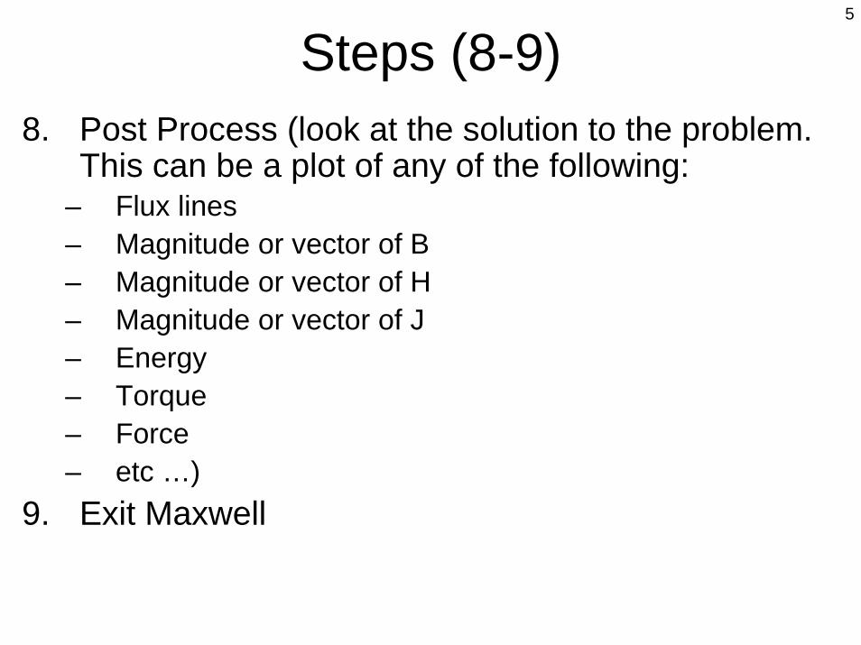
Steps (8-9)8. Post Process (look at the solution to the problem.
This can be a plot of any of the following:– Flux lines– Magnitude or vector of B– Magnitude or vector of H– Magnitude or vector of J– Energy– Torque– Force– etc …)
9. Exit Maxwell
6
Example• The best way to learn this is to try an example
yourself.• I would suggest that you make a copy of this
document in order to follow along as you work through the example.
• The next page shows what we will create and then produce a plot of the flux lines and a plot of the field strength.
7
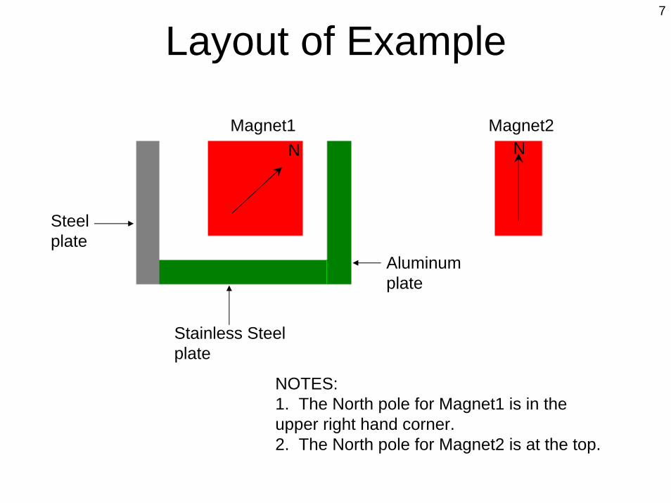
Layout of Example
Steel plate
Stainless Steel plate
Aluminum plate
Magnet1 Magnet2N N
NOTES: 1. The North pole for Magnet1 is in the upper right hand corner.2. The North pole for Magnet2 is at the top.

8
Field Lines of Example

9
Download & Install• Let’s get started.• You need to
download and install Maxwell 2D SV (student version) onto your computer. It can be found at:http://www.ansoft.com/
maxwellsv/

10
System Requirements• You need to have
Windows NT or 2000 or XP in order to run this program.
• Windows 98SE might work, but there is no guarantee nor support.

11
Sample Projects• Don’t forget to also
download their Getting Started Guides and Sample Projects.
• These guides are a little more advanced than this Basic User Manual. They will help you work on other problems.

12
Users• Be sure you meet
the criteria they require for a free copy of this excellent program.
• The download size is about 36MB –so use a high speed internet connection!

13
Step 1a• On your desktop is the icon for this.• Double click the icon to start the program.

14
Step 1b• This is the main toolbar.• Click on [PROJECTS].

15
Step 1c• This is where you
manage your Maxwell projects.
• Click on [New…].

16
Step 1d• This is where you enter
the project name.• Type “test001” in for the
‘Name:’ as shown in the lower screen shot.
• Make sure there is a check mark for ‘Open project upon creation’.
• Then click [OK].
17
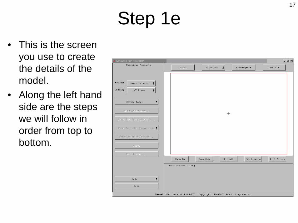
Step 1e• This is the screen
you use to create the details of the model.
• Along the left hand side are the steps we will follow in order from top to bottom.
18
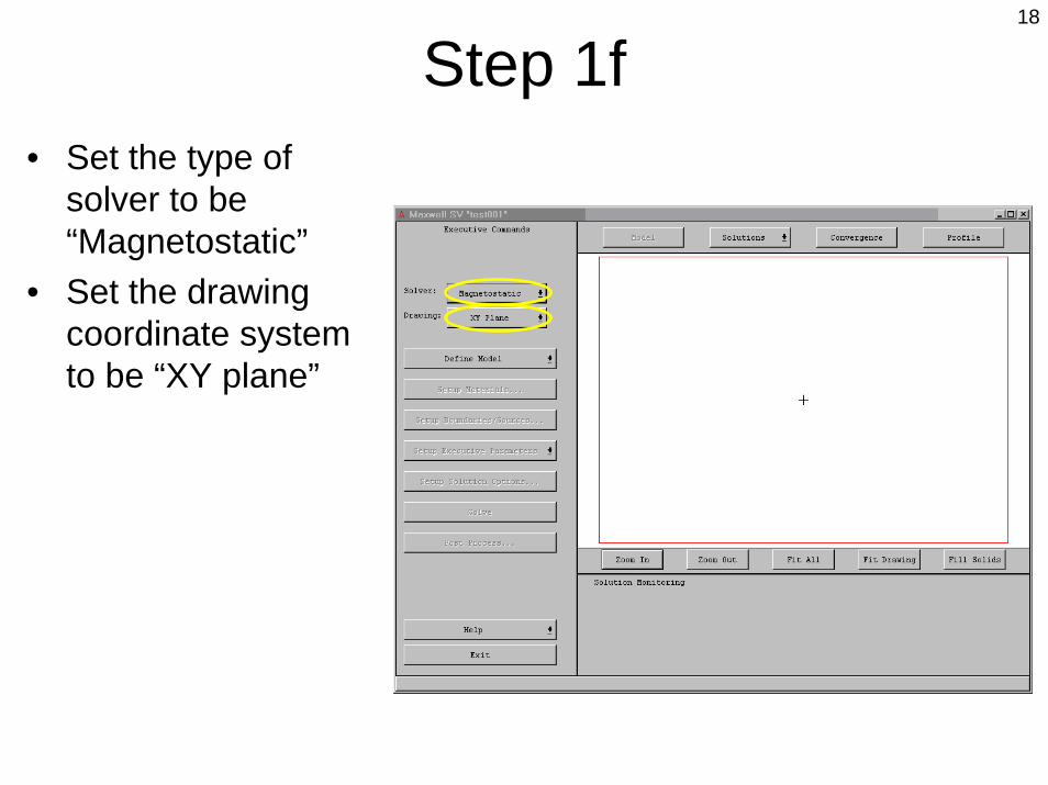
Step 1f• Set the type of
solver to be “Magnetostatic”
• Set the drawing coordinate system to be “XY plane”

19
Step 2a• Now we draw the
objects.• Click on [Define
Model]

20
Step 2b• This is the new
screen and set of tools you get after you click on [Define Model]
• This is where you draw the magnets and other objects

21
Step 2c• The tools are basic
drawing tools. We’ll use the rectangle drawing function.
• After clicking on the rectangle in the toolbar, go to the screen and click the top left corner for the magnet.
• Then click the lower right corner to complete the magnet.

22
Step 2d• After you draw an
object, this window appears. It asks you for a name of the object and what color you want it to be.
• We will leave the name as “object1”and leave the color as red.
• Click [OK].

23
Step 2e• Use the same tool
to draw this rectangle.
• The name will be “object2”.
• Make the color grey.
24
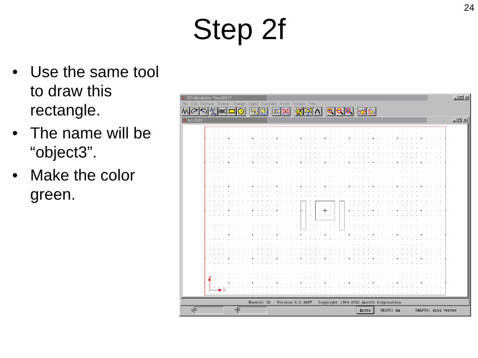
Step 2f• Use the same tool
to draw this rectangle.
• The name will be “object3”.
• Make the color green.
25
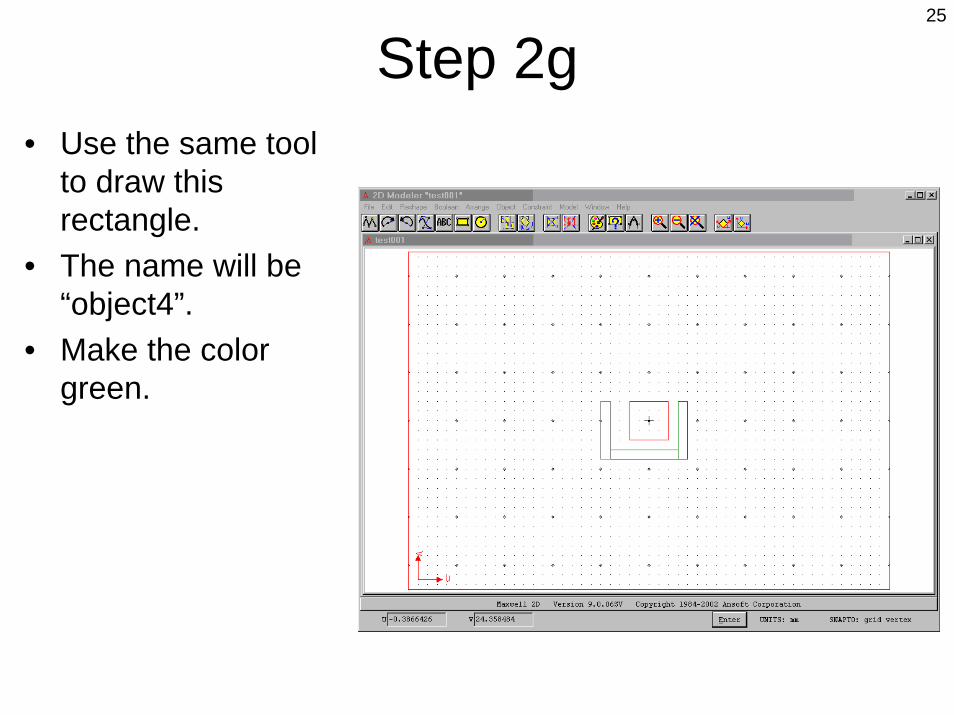
Step 2g• Use the same tool
to draw this rectangle.
• The name will be “object4”.
• Make the color green.

26
Step 2h• Use the same tool
to draw this rectangle.
• The name will be “object5”.
• Keep the color red.

27
Step 2i• To exit this
window, go to File, Exit.
• When the small window appears, click on [Yes].
28
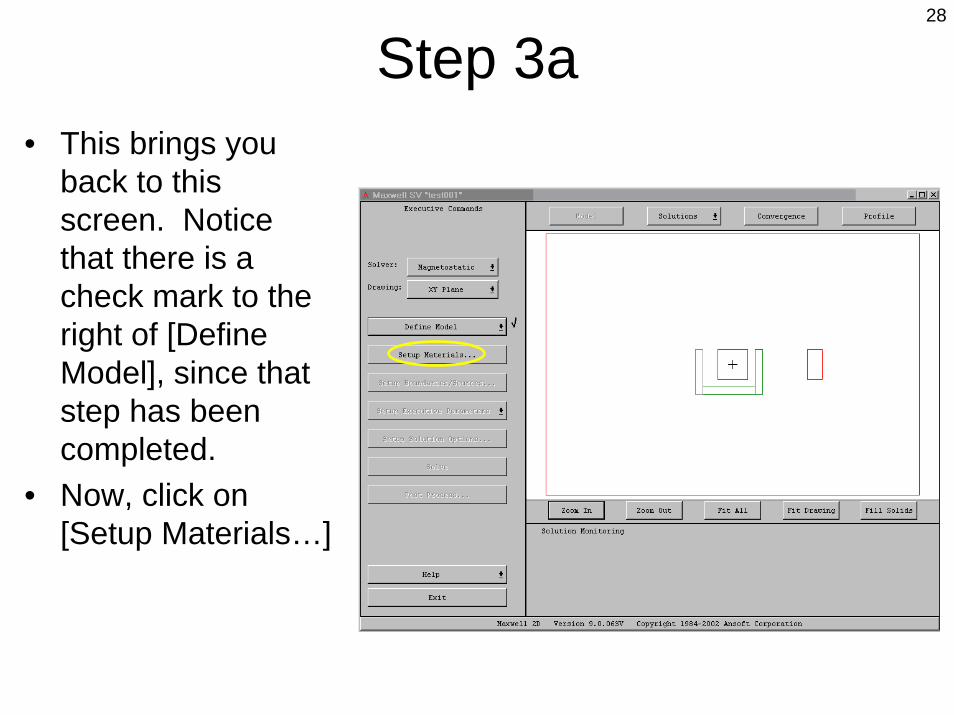
Step 3a• This brings you
back to this screen. Notice that there is a check mark to the right of [Define Model], since that step has been completed.
• Now, click on [Setup Materials…]

29
Step 3b• This screen allows
you do define what material each object is made of.
30
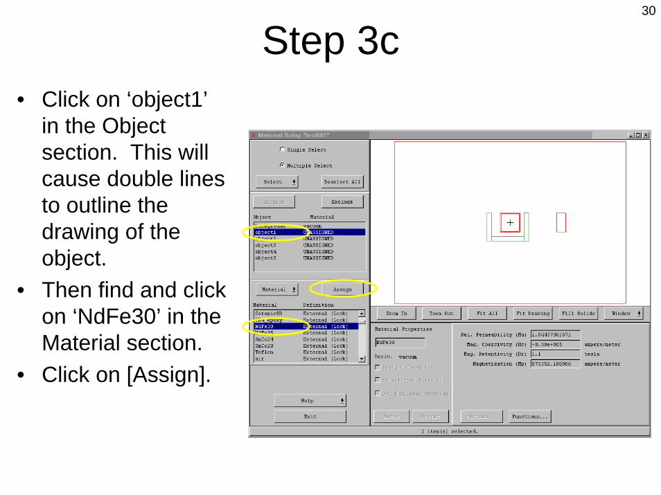
Step 3c• Click on ‘object1’
in the Object section. This will cause double lines to outline the drawing of the object.
• Then find and click on ‘NdFe30’ in the Material section.
• Click on [Assign].
31
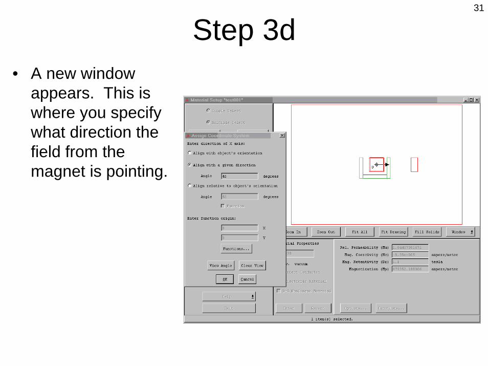
Step 3d• A new window
appears. This is where you specify what direction the field from the magnet is pointing.

32
Step 3e• Click on ‘Align with
a given direction”• Fill in “45” for the
angle• Remember that 0
degrees points to the right, 90 deg points up, 180 deg points to the left, and 270 deg points down.
• Click on [OK]
33
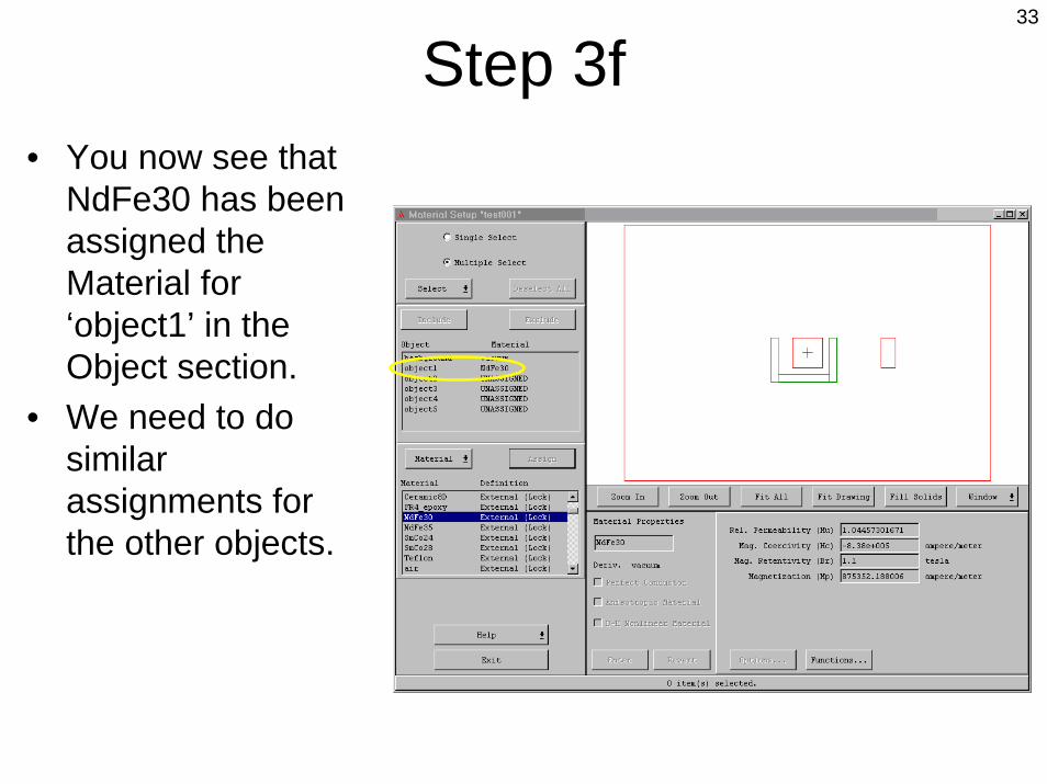
Step 3f• You now see that
NdFe30 has been assigned the Material for ‘object1’ in the Object section.
• We need to do similar assignments for the other objects.

34
Step 3g• Click on ‘object5’• Click on ‘NdFe30’• Click on [Assign]

35
Step 3h• Click on ‘Align
with a given direction’
• Fill in 90 for the degrees angle
• Click on [OK].

36
Step 3i• Click on ‘object2’
37
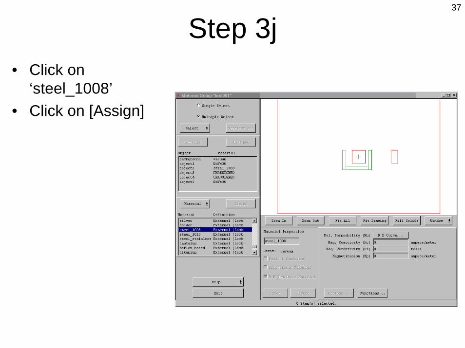
Step 3j• Click on
‘steel_1008’• Click on [Assign]

38
Step 3k• Click on ‘object3’

39
Step 3l• Click on
‘aluminum’• Click on [Assign]
40
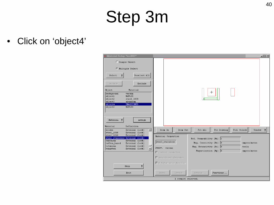
Step 3m• Click on ‘object4’

41
Step 3n• Click on
‘steel_stainless’• Click on [Assign]

42
Step 3o• Click on [Exit]• This small
confirmation window appears.
• Click on [Yes]

43
Step 4a• We are back to
this window.• Note the check
mark next to the [Setup Materials…]
• Click on [Setup Boundaries / Sources…]

44
Step 4b• This is where we
specify what happens outside the big red box and if there is any current flowing in any object.

45
Step 4c• Click on Edit,
Select, Object, By Clicking
• Then, take the pointer and click it onto the red boundary rectangle. You may have to be a little bit to the left or right.
• After that, right click your mouse.

46
Step 4d• Click onto the
balloon button.
47
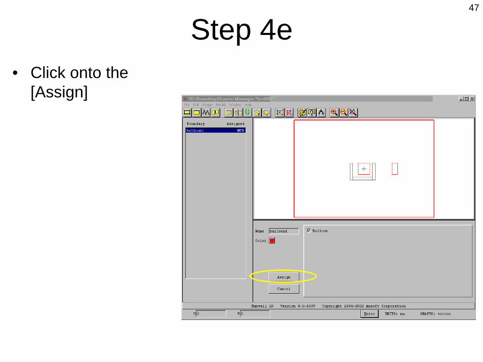
Step 4e• Click onto the
[Assign]
48
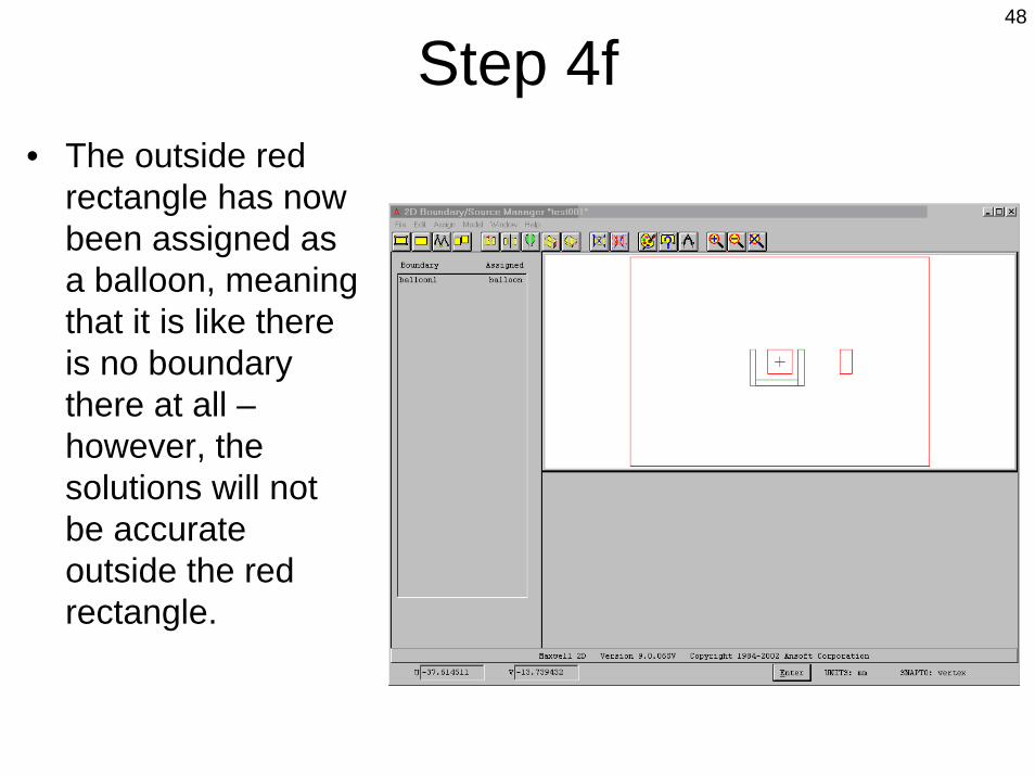
Step 4f• The outside red
rectangle has now been assigned as a balloon, meaning that it is like there is no boundary there at all –however, the solutions will not be accurate outside the red rectangle.
49
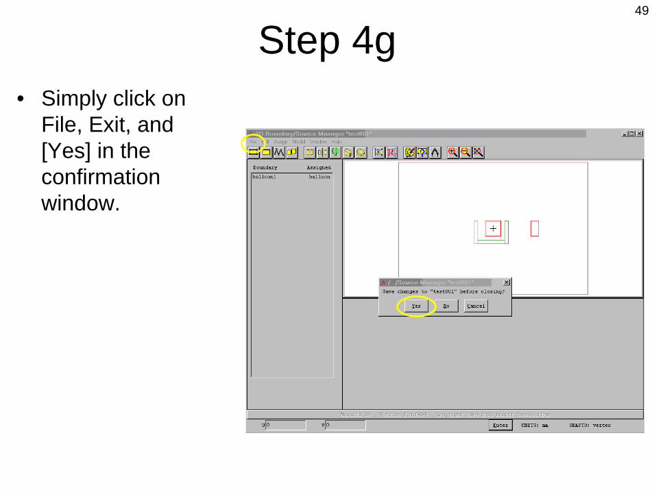
Step 4g• Simply click on
File, Exit, and [Yes] in the confirmation window.

50
Step 5a• There is now a
check mark next to [Setup Boundaries / Sources…]
• We do not need to do anything with [Setup Executive Parameters]
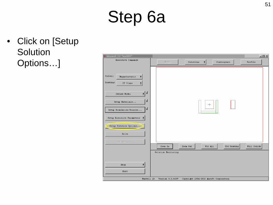
51
Step 6a• Click on [Setup
Solution Options…]

52
Step 6b• This window
appears.

53
Step 6c• I usually set the
‘Percent error’value to 0.001.
• This will cause the simulation to run longer, but the flux lines will be much smoother.
• Click on [OK]
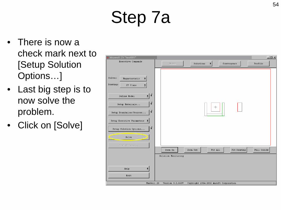
54
Step 7a• There is now a
check mark next to [Setup Solution Options…]
• Last big step is to now solve the problem.
• Click on [Solve]

55
Step 7b• While the program
is solving the problem, you will see the Solution Monitoring window. The red bar in the window will go to 100 several times as it is working on the solution.

56
Step 7c• Finally, this
window will pop up saying that the solution is complete.
• Click on [OK]

57
Step 8a• There is now a
check mark next to [Solve]
• In order to see the results, click on [Post Process…]

58
Step 8b• This is a new
window that will show us the results and all the cool stuff you want to see.

59
Step 8c• Click on the
Coordinates button three times to change the look of the axis and to remove them.
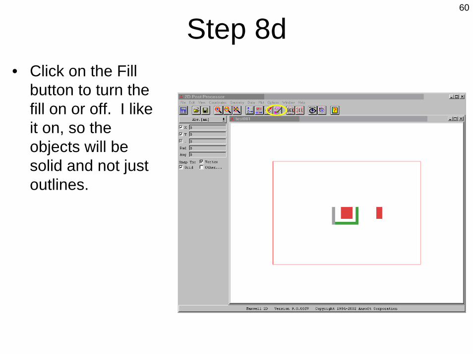
60
Step 8d• Click on the Fill
button to turn the fill on or off. I like it on, so the objects will be solid and not just outlines.

61
Step 8e• Click on Plot, Field
to bring up this window to select what you want to plot.

62
Step 8f• Click on ‘Flux
Lines’ in the left hand column
• Click on ‘Surface –all-’ in the middle column
• Click on [OK]

63
Step 8g• This window asks
for more information regarding what you want the plots to look like.

64
Step 8h• I usually turn off
the ‘Show color key’
• Then I increase the ‘Divisions’ to 30 (better if it is an even number)
• Click [OK]

65
Step 8i• There! You now
have a plot of the flux lines due to the arrangement of objects you defined.
• But wait! There’s more!

66
Step 8j• It is easy to zoom
into the plot in order to see what is going on in different places.
• Simply click on the ‘Magnify’ button, click at the upper left corner of what you want to fill the screen, then click at the lower right corner.

67
Step 8k• If you want to see
some other kind of plot, click on Plot, Delete
• This window will show you what is presently being displayed.
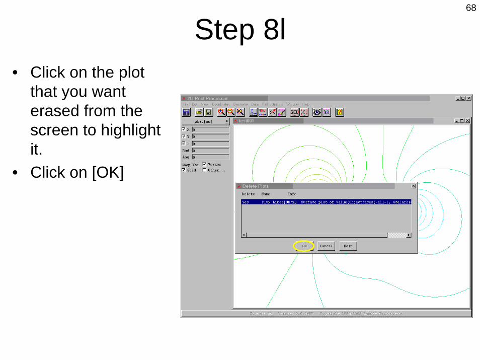
68
Step 8l• Click on the plot
that you want erased from the screen to highlight it.
• Click on [OK]

69
Step 8m• Click on [Yes]

70
Step 8n• You are back to a
clean screen.

71
Step 8o• Let’s look at the
magnetic field that is present around the objects.
• Click on Plot, Field• Click on ‘Mag B’ in
the left hand column
• Click on ‘Surface background’ in the middle column
• Click on [OK]

72
Step 8p• Leave everything
as it is.• Click [OK]
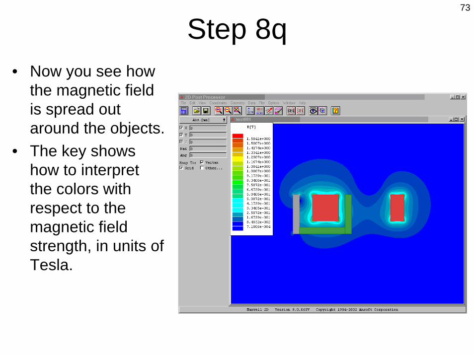
73
Step 8q• Now you see how
the magnetic field is spread out around the objects.
• The key shows how to interpret the colors with respect to the magnetic field strength, in units of Tesla.

74
Step 8r• You can zoom into
this the same way as before.

75
Step 9a• What do you do if
you now want to exit the Maxwell program?
• First, close this screen by clicking on File, Exit.
• Then click [Yes] in the confirmation window.

76
Step 9b• Click on [Exit]
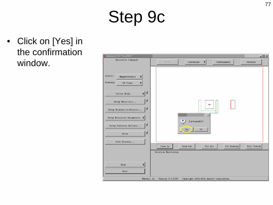
77
Step 9c• Click on [Yes] in
the confirmation window.

78
Step 9d• Before you leave,
you can click on a project name and see a rough picture of it in the window.
• Since this is new, you may need to click on a different project name and then back to this one.
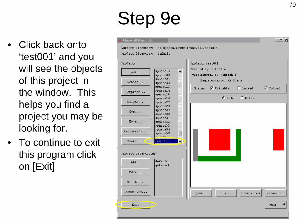
79
Step 9e• Click back onto
‘test001’ and you will see the objects of this project in the window. This helps you find a project you may be looking for.
• To continue to exit this program click on [Exit]

80
Step 9f• Click on [Exit] in the
top bar• Click [Yes] in the
confirmation window• That’s all, folks!