basic study of smart robotic construction lift for ... · basic study of smart robotic construction...
TRANSCRIPT

Robot Technology
266
Basic Study of Smart Robotic Construction Lift For Increasing Resource Lifting Efficiency in High-Rise Building Construction
Chang-Yeon, Cho1; Soon-Wook, Kwon 2; Junbok Lee3 , Suk-Jun,You 4 Sang-Yoon-Chin 5 and Yea-Sang, Kim 6
1 Dept. of Architecture & Civil Engineering, Sungkyunkwan University,Suwon-si, Korea, P.O. Box 440-746, PH(82)31-299-4772 ; FAX(82)31-290-7570 ; e-mail :[email protected] 2 Dept. of Architecture & Civil Engineering, Sungkyunkwan University,Suwon-si, Korea, P.O. Box 440-746, PH(82)31-299-4765 ; FAX(82)31-290-7570 ; e-mail :[email protected] 3 College of Architecture & Civil Engineering, Kyung Hee University, Yongin-si, Korea, P.O. Box 449-701, PH(82)31-201-2541 ; FAX(82)31-204-6780 ; e-mail : [email protected] 4 Dept. of Architecture & Civil Engineering, Sungkyunkwan University,Suwon-si, Korea, P.O. Box 440-746, PH(82)31-299-4772 ; FAX(82)31-290-7570 ; e-mail : [email protected] 5 Dept. of Architecture & Civil Engineering, Sungkyunkwan University,Suwon-si, Korea, P.O. Box 440-746, PH(82)31-290-7568 ; FAX(82)31-290-7570 ; e-mail : [email protected] 6 Dept. of Architecture & Civil Engineering, Sungkyunkwan University,Suwon-si, Korea, P.O. Box 440-746, PH(82)31-290-7561 ; FAX(82)31-290-7570 ; e-mail :[email protected]
Abstract
Most high-rise buildings are erected in downtown areas, where on-site storage space for construction materials is typically insufficient due to limited spaces. Just-In-Time (or JIT) concept has been adopted so that necessary stock materials and storage spaces can be reduced; for high-rise buildings, however, transporting materials vertically using lifts still poses significant efficiency because its efficiency drops exponentially as the building height grows.
Most of current efforts to counter this problem mainly focus on developing smart tower cranes, whereas lift has gathered less attention in this respect.
This research aims to develop a robotic lift capable of autonomous operations at night time, based on the intelligent lift development toolkit which was previously developed by the authors. It is now in a preliminary study phase.
This study proposes a concept model of the robotic lift system and its operation plans, utilizing several technologies such as an optimized material dispatch algorithm and ubiquitous sensor networks (USNs). The proposed system can be relayed to the horizontal transportation robots located in each floor to move the lifted materials to their destinations.
The outcome from this study will contribute to the improvement of the overall efficiency of the high-rise building construction logistics and space constraints of the construction site. It is also expected that the mechanical performance of the existing lift system can be benefited from this research.
When overall system development, including optimized operation planning model and monitoring subsystem, is finished, it will contribute to innovation of the construction technology. Keywords: Smart Lift, Robotic Construction Lift, High-rise building construction, operation optimization, concept model
1. Introduction and Motivation According to 'Skyscraper' webzine, around the globe there are so many ongoing highrise building projects,
and competition among the new economic giants such as China and Dubai for the tallest building is apparent. The examples include Chicago Spiral building (150 floors, 610m), Ablaza Al Bite building (76 floors, 595m), Russia's Federation Tower (93 floors, 506m), World Finance Center in Shanghai (101 floors, 492m), etc.
According to an earlier research (Lee et al. 2008 ), height of a building in construction affects efficiency of lifting equipments installed on site, which also affects the overall schedule. Current generation of the lifts fall short of meeting the field needs, because they aren’t fast enough (typically 100-150m/min) to elevate

26th International Symposium on Automation and Robotics in Construction (ISARC 2009)
267
materials to the desired floor on time if the floor is located above 300m; as a result, overall schedule is significantly affected from it.
To counter the efficiency issue, various techniques from working overtime to Six Sigma have been applied, only to reveal other issues such as workplace safety and optimization problems due to spatial and temporal constraints.
This research aims to develop fundamental concepts for next generation lift systems which allow higher efficiency and better management using intelligent control. To achieve this goal, the authors have analyzed existing lift systems with respect to their feasibility for high-rise application.
2. Construction Lift (Literature Reviews)
2.1 Classification of the lift systems There are several different lift types commonly used in construction sites: first, construction hoists which
move materials and men vertically; second, simpler ones which resemble passenger elevators and used for smaller loads; third, hydraulic ones. Construction lifts may be further sub-categorized into a low speed type, a medium speed type, a high speed type; a high capacity type, and special types. These types can be briefly described as follows:
a. Low-speed type: most commonly used in construction sites. Suitable for lower-rise buildings such as community housing and office buildings. Typical speed for this type is 38m/min, and maximum lifting height is typically 150m; also, its nominal load is 1.0 ~ 1.2 tons.
b. Medium-speed type: Suitable for medium-to-high rise projects. Hoists of this type generally have better loading capacity than the low-speed ones. Their maximum installable hight is 150m to 300m, and their nominal load is 1.5 tons to 2.0 tons.
c. High capacity type: designed to increase lifting efficiency in mid-to-high rise projects. Its speed is virtually same as the low speed type, but can be installed to higher places (maximum installation height: 150m to 200m), with increased nominal load (1.2 tons to 2.0 tons).
d. High speed type: designed specifically for high-rise projects. Its speed is 100m/min, maximum installation height is at least 350 meters, and nominal load is 2.5 tons to 3.0 tons.
Table 1. Summarizes the performance of these lift types. Seen in the table, their mechanical performance differences come from the use of inverters, and location of the drive motors.
types Nominal loads (ton)
Lifting speed
(m/min)
dimension of the
loading room (m)
Max. size of the door
opening(m)
Frequency of
power alternatio
n (Hz)
Nominal power
consumption
(KVA)
Location of the
drive motors
Use of inverter
s
Low speed 1.0-1.2 38 1.27x2.9x2.
5 1.27x2.4 50/60 2x27KVA internal no
Med speed 1.2-1.5 70 1.5x4.0x2.6
5 1.5x2.6 50/60 2x47KVA rooftop yes
High capacit
y 1.2-2.0 38 1.5x4.0x2.6
5 1.5x2.6 50/60 2x75KVA rooftop yes
High speed 2.0-3.0 100 1.5x4.5x2.6
5 1.5x2.6 50/60 2x64KVA rooftop yes
2.2 Mechanical performance of construction hoists and survey of existing
Figure 1 illustrates the nomenclature of a typical construction hoist. It is mainly composed of a loading cage (which actually move people and materials vertically), a mast which sustains the cage, a rack-and-pinion gear assembly which converts rotational force to vertical movement (for driving the cage), and a

counterweigh
A hoist ca
can be adjuste
2.3 Survey of pFor the au
Automation ior regional rematerial moveSouth Korea new equipme
(Lee JB an30-40 floors. lessening hoisscheduling wadetermining ooptimization
3. As-is Prob
3.1 Analysis ofIn our pre
designated he
Time ne
Table 2 sh
hoist types if work time is e
ht system. Det
Figure
an determine wed with magne
precedent researchuthors, it was un Constructiosearch articlesement focusedappeared to dnts. They are
nd Han CH, 2(Chung et. al, st workloads. Ias proposed tooptimum numprocess of th
blem Stateme
of of daily hoist tevious researcheight, whose ap
eeded to lift
hows the numbthey were ins
estimated to 8
ails of the driv
e 1. Typical Co
where it is locaetic markers p
hes unable to findon- the search s might have bd on tower cra
discuss managesummarized a008) evaluated2004) sugges
In (Lee et. al, o implement j
mber of hoists e hoist schedu
ents
travels with respeh, efficiency opproximate va
= {average li
ber of estimattalled in Burj
8 hours, and M
Robot Tech
2
ive train are ill
onstruction L
ated by countiplaced in each
d any known rewas by no me
been omitted)anes and consement techniqas follows: d economic feted pre-fabric2004), as a paust-in-time deneeded in sys
ules for finish
ect to lifting heigof a hoist can alue can be ca
ifting height loading and
ted single lift tAl Arab Hote
Machines are o
hnology
268
lustrated in Fig
Lifts and Detai
ing teeth of thfloor.
esearches in (aeans exhaustiv; on the other
struction roboques for lifting
easibility of uscation and careart of enterprielivery. (Kim astematic mannworks.
ght be measured b
alculated using
(m) / liftingd unloading)
times and totael project, whioperated in 70%
gure 2.
ils of the Driv
he pinion gear
at least in Jourve, as some unr hand, most rots. Majority og efficiency ra
sing medium sefully plannedise resource pland Han, 2008ner. (Park et. a
by the time neg the following
g speed (m/m)
al number of ich is 321 met% to their full
ve Train
r while it is ro
rnals of ASCEndisclosed techresearches for f domestic rether than deve
speed hoists ind load-balancinlanning, impro8) proposed a al, 2001) discu
eeded to lift thg expression:
min) x2 } + le
daily travels oters high. In thl capability.
otating, which
E and hnical reportsautomated searches in elopment of
n buildings ofng for oved hoist processof ssed
hings to the
ead time (for
of different his table, daiy
s
f

26th International Symposium on Automation and Robotics in Construction (ISARC 2009)
269
Table 2. The number of estimated single lift times and total number of daily travels of different hoist types
Lifting height
(m)
Lead time (min)
Low speed type Medium speed type High speed type Time of single lift
(min)
Number of daily travels (travels/day)
Time of single lift
(min)
Number of daily travels (travels/day)
Time of single lift
(min)
Number of daily travels (travels/day)
20 10 11.05 31 10.57 32 32.00 33 40 10 12.11 28 11.14 31 31.00 32 60 10 13.16 26 11.71 29 29.00 31 80 10 14.21 24 12.29 28 28.00 30 100 10 15.26 23 12.86 27 27.00 29 120 10 16.32 21 13.43 26 26.00 28 140 10 17.37 20 14.00 24 24.00 28 160 10 18.42 19 14.57 24 24.00 27 180 10 19.47 18 15.14 23 23.00 26 200 10 20.53 17 15.71 22 22.00 26 220 10 21.58 16 16.29 21 21.00 25 240 10 22.63 15 16.86 20 20.00 24 260 10 23.68 15 17.43 20 20.00 24 280 10 24.74 14 18.00 19 19.00 23 300 10 25.79 14 18.57 19 19.00 23 320 10 26.84 13 19.14 18 18.00 22
Figure 2. Time needed to lift with respect to lifting height
11.05 12.11 13.16 14.21
15.26 16.32 17.37 18.42
19.47 20.53 21.58 22.63
23.68 24.74 25.79 26.84
10.57 11.14 11.71 12.29 12.86 13.43
14.00 14.57 15.14 15.71 16.29 16.86
17.43 18.00 18.57 19.14
10.33 10.67 11.00 11.33 11.67 12.00 12.33 12.67
13.00 13.33 13.67 14.00 14.33 14.67 15.00 15.33
Lifting height (m)
20 40 60 80 100 120 140 160 180 200 220 240 260 280
Time needed to lift with respect to lifting height
low speed type Time needed to lift (min)
medium speed type Time needed to lift (min)
high speed type Time needed to lift (min)

Robot Technology
270
Figure 3. Number of daily hoist travels with respect to lifting height
According to Table 2, Figure 2 and Figure 3, number of hoist travels decreases as building height
increases. For Burj Al Arab (321m), its daily travel would be limited to 22. For high-speed lifts For different lead times ranging from 5 to 10 minutes, Table 3 and Figure 4 shows their effects.
Table 3. Sensitive Analysis For different lead times ranging from 5 to 10 minutes Lifting height
leadtime 10min
leadtime 9min
Leadtime 8min
leadtime 7min
leadtime 6min
leadtime 5min
20 32.52 36.00 40.32 45.82 53.05 63.00 40 31.50 34.76 38.77 43.83 50.40 59.29 60 30.55 33.60 37.33 42.00 48.00 56.00 80 29.65 32.52 36.00 40.32 45.82 53.05 100 28.80 31.50 34.76 38.77 43.83 50.40 120 28.00 30.55 33.60 37.33 42.00 48.00 140 27.24 29.65 32.52 36.00 40.32 45.82 160 26.53 28.80 31.50 34.76 38.77 43.83 180 25.85 28.00 30.55 33.60 37.33 42.00 200 25.20 27.24 29.65 32.52 36.00 40.32 220 24.59 26.53 28.80 31.50 34.76 38.77 240 24.00 25.85 28.00 30.55 33.60 37.33 260 23.44 25.20 27.24 29.65 32.52 36.00 280 22.91 24.59 26.53 28.80 31.50 34.76 300 22.40 24.00 25.85 28.00 30.55 33.60 320 21.91 23.44 25.20 27.24 29.65 32.52
30 27 25 23 22 20 19 18 17 16 15 14 14 13 13 12
31 30 28 27 26 25 24 23 22 21 20 19 19 18 18 17
32 31 30 29 28 28 27 26 25 25 24 24 23 22 22 21
Number of daily hoist travels with respect to lifting height
Daily hoist travels (Travels/day) low speed type
Daily hoist travels (Travels/day) medium speed type
Daily hoist travels (Travels/day) high speed type

26th International Symposium on Automation and Robotics in Construction (ISARC 2009)
271
Figure 4. a high speed hoist’s sensitivity to lead time affecting its efficiency
To improve the efficiency issues, substantial changes in existing hoist mechanism and their shape are
obviously desirable; however, for seeking ready-to-use options, shrinking the lead time to the minimum seems to be a reasonable approach.
3.2 Analysis of existing work process To understand the lead time in detail, we attempted to analyze the existing work process. We divide the
workers related to hoist operation into two groups; the one for ground-level crews loading the hoist with materials, and the other for destination-level crews unloading the delivered materials. Figure 5 is a flow diagram of the work process.
In this figure, workflows of two work crews (ground-level crews and destination level ones) are clearly identified. At the ground-level floor, the crews would use the entrance door where as the destination crews would use the exit door.
The ten-minute lead time assumed in Table 2 corresponds to the ‘stand-by’ time in Figure 6, which implies that reduced crew-work would positively affect the stand-by time. Further breakdown of the workflow for both crew groups (and their time consumption) can be drawn as Figure 6.
Let Tc1 (stand for Check Time) for the time needed for ground crew to identify total amount of the material to be loaded, Tl for the time needed to load the hoist. The stand-by time is then described as Tc1 + Tl. Likewise, Let Tc2 and Tu for the check time and time unloading time of the destination floor crews respectively. The stand-by time for the destination floor crew is described as Tc2 + Tu also.
Therefore, Total standby time (denoted as Ts) in a single lift cycle can be summarized in the following expression. Our intelligent hoist concept intends to reduce Ts, which will be further described in following chapters.
4. Automation Technology Analysis
4.1 Available technologies Barcode systems have been used for supply chain management, which is being replaced by newer RFID
32.52 31.50 30.55 29.65 28.80 28.00 27.24 26.53 25.85 25.20 24.59 24.00 23.44 22.91 22.40 21.91
36.00 34.76 33.60 32.52 31.50 30.55 29.65 28.80 28.00 27.24 26.53 25.85 25.20 24.59 24.00 23.44
40.32 38.77 37.33 36.00 34.76 33.60 32.52 31.50 30.55 29.65 28.80 28.00 27.24 26.53 25.85 25.20
45.82 43.83 42.00 40.32 38.77 37.33 36.00 34.76 33.60 32.52 31.50 30.55 29.65 28.80 28.00 27.24
53.05 50.40 48.00 45.82 43.83 42.00 40.32 38.77 37.33 36.00 34.76 33.60 32.52 31.50 30.55 29.65
63.00 59.29
56.00 53.05 50.40 48.00 45.82 43.83 42.00 40.32 38.77 37.33 36.00 34.76 33.60 32.52
a high speed hoist’s sensitivity to lead time affecting its efficiency
Lead time 10 min 9 min 8 min
7 min 6 min 5 min

Robot Technology
272
systems. Bar code readers have shorter recognition ranges, with inability to scan multiple tags at a time, whereas RFIDs have longer ranges and simultaneous scanning capability.
Figure 5. Flow diagram of As-is work process
Figure 6. the workflow for both crew groups
In South Korean research society, RFIDs are explored with USN (Ubiquitous Sensor Network) for
managing logistics in construction sites. Among the listed researches, in the ‘Next generation intelligent construction logistics automation system’,
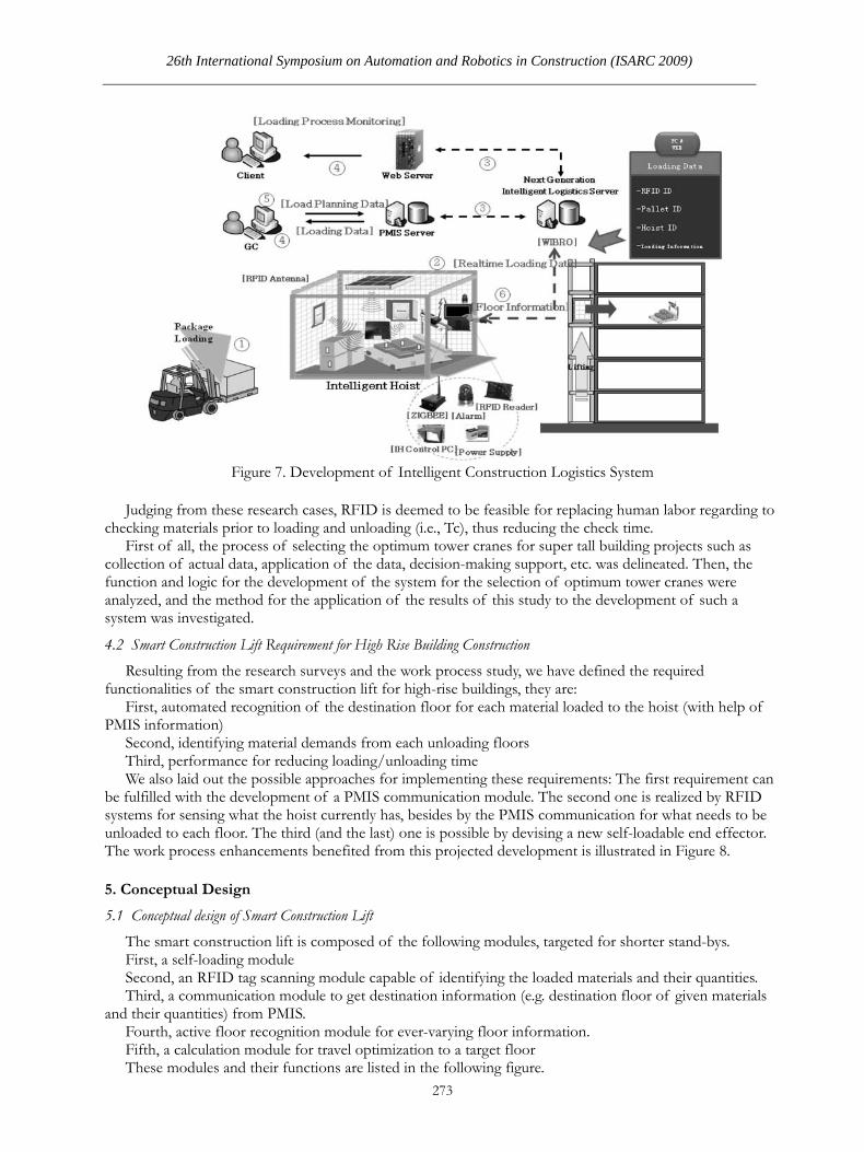
now in its 3rd year, a toolkit for RFID material recognition, which is applicable to hoists as well enabling automatic request of the materials from each floor to the sensor-equipped hoist, is under development. The research also proved that the RFID-based system can interact with real-time construction project management system. The following Figure 7(Research report: An intelligent construction logistics automation system. Ministry of land, transportation, and maritime affairs) is a summary of this research.
26th International Symposium on Automation and Robotics in Construction (ISARC 2009)
273
Figure 7. Development of Intelligent Construction Logistics System
Judging from these research cases, RFID is deemed to be feasible for replacing human labor regarding to
checking materials prior to loading and unloading (i.e., Tc), thus reducing the check time. First of all, the process of selecting the optimum tower cranes for super tall building projects such as
collection of actual data, application of the data, decision-making support, etc. was delineated. Then, the function and logic for the development of the system for the selection of optimum tower cranes were analyzed, and the method for the application of the results of this study to the development of such a system was investigated.
4.2 Smart Construction Lift Requirement for High Rise Building Construction Resulting from the research surveys and the work process study, we have defined the required
functionalities of the smart construction lift for high-rise buildings, they are: First, automated recognition of the destination floor for each material loaded to the hoist (with help of
PMIS information) Second, identifying material demands from each unloading floors Third, performance for reducing loading/unloading time We also laid out the possible approaches for implementing these requirements: The first requirement can
be fulfilled with the development of a PMIS communication module. The second one is realized by RFID systems for sensing what the hoist currently has, besides by the PMIS communication for what needs to be unloaded to each floor. The third (and the last) one is possible by devising a new self-loadable end effector. The work process enhancements benefited from this projected development is illustrated in Figure 8.
5. Conceptual Design
5.1 Conceptual design of Smart Construction Lift The smart construction lift is composed of the following modules, targeted for shorter stand-bys. First, a self-loading module Second, an RFID tag scanning module capable of identifying the loaded materials and their quantities. Third, a communication module to get destination information (e.g. destination floor of given materials
and their quantities) from PMIS. Fourth, active floor recognition module for ever-varying floor information. Fifth, a calculation module for travel optimization to a target floor These modules and their functions are listed in the following figure.

The data f
5.2 Proposed cFor each m
1. as M2. 3.
Figure 8. Wor
flow between
conceptual designmodule in Sma
CommuniMobile WiMax
RFID moFloor reco
rk process enh
Figure
the modules a
n for Smart Consart Constructiication modulx, WiFi, or Celdules can be iognition modu
Robot Tech
2
hancements b
9. Smart Cons
and the tasks p
struction Lift ion Lift, they les can be reallular networkimplemented uule can be im
hnology
274
benefited from
struction Lift
performed by
can be realizealized using wk. using the RFIplemented wi
m this projecte
Modules
y each module
d using the fowireless comm
ID readers andith an encoder
d developmen
is illustrated i
ollowing technmunication tec
d antennae r, a pinion gea
nt
in Figure 11.
nologies. hnologies suc
ar counter, an
ch
nd
m4o5
The cothe Smart
For im
conveyed be better.
For wirto fare wel
For RFwaves cau
5.3 ExpecAs men
increased
26th Internatio
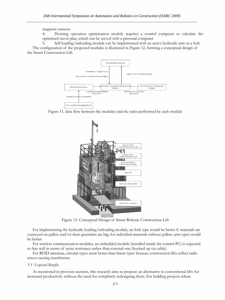
magnetic sens4. Hoistinoptimized trav5. Self loaonfiguration o
Construction
Figure 11.
Fi
mplementing thon pallets and
reless commull in terms of
FID antennae,sing interferen
cted Benefits ntioned in preproductivity w
onal Symposium
ors. ng operation vel plan, whichading/unloadif the propose
n Lift.
data flow betw
igure 12. Conc
he hydraulic lod/or their qua
unication modnoise resistan
, circular typesnce
evious sectionwithout the ne
m on Automati
optimizationh can be serveing module caed modules is
ween the mod
ceptual Design
oading/unloadantities are big
ules, an embence rather thans seem better
ns, this researcheed for compl
ion and Roboti
275
n module reqed with a persan be implemeillustrated in F
dules and the t
n of Smart Ro
ding module, ag; for individua
edded module n external onethan linear typ
h aims to propetely redesign
ics in Construc
quires a contonal computeented with an Figure 12, for
tasks perform
obotic Constr
an fork type wal materials wi
(installed insie (hooked up vpes because co
pose an alternning them. For
ction (ISARC 2
trol computerer
active hydrauming a conce
med by each m
uction Lift
would be betteithout pallets,
ide the controvia cable). onstruction lif
native to conver building proj
009)
r to calculate
ulic arm or a foptual design o
odule
er if materials arm types wo
l PC) is expec
fts reflect radi
entional lifts fjects where
e the
ork of
are ould
cted
io
for

vertical transpmaximized.
The expecbelow.
T
- 1 : a- 2 : a- 3 :au
A to-be-delabors neededvarious measudestination flocurrent locatiunmanned oparea operation
6. Conclusio
The authosummarized a
First, autoSecond, wThird, opt
of the lift usinFourth, auFifth, autoSixth, sendOnce reali
materials to hthe lifts. Furthwill contributapproaches tomoney and tim
References
[1] Researchtranspor
[2] Lee, J.BBuildingInstitute
[3] Ho, J.KKICEM
port accounts
cted benefits o
Table 4. as-is lo
automated loaautomated syutomated floeveloped hydrd for those opures such as: uoor of a givenon which will
peration that wns thanks to s
ons and Furth
ors have propoas follows: omatic loadingwireless commutimization capng the optimizutomatic operaomatic unloadding informatized, the smar
higher locationher research pte to the consto completely rme, besides th
h report: Anrtation, and m. et. al.(2008)
g Construction 9( 3), pp. 185. (2007). A S. 8(6). (Korean
for significan
of the propose
ogistic manage
ading systemstem using Ror sensing usraulic arms anerations). Also
utilizing RFIDn package with
be implemenwon’t require hhortened lead
her Studies
osed a concep
g/unloading caunication with
pability in travezed plan ation to the ta
ding upon arrivtion about unlrt constructionns often causeplans include ttruction indusreplace the exihe cost of ‘tria
n intelligent aritime affairs) A Feasibilitn, Journal of5-193 (KoreanSystem for then)
Robot Tech
2
nt amount of c
ed smart lift s
ement matrix
m using hydraRFID sing light sen
nd forks will eno, overall lead
D-based automh help of onbnted using lighhuman operatd time.
pt of a smart c
apability whichh PMIS el planning wi
arget floor. val at the targeoaded materian lift will help overall constr
the prototype stry by demonisting rack-andal-and-errors’.
constructions (Republic of ty Study on Of Korea Instn) e Selection fo
hnology
276
construction s
ystem can be
Table 5. To-b
aulic arms or
nsor and enconable automat
d time requiredmatic logging, a
oard control cht sensors and tors, and they
construction li
h enables unm
ith help of PM
et floor als to PMIS inlogistics in hi
ruction scheddevelopment
nstrating a costd-pinion mech
n logistics af Korea). Optimal Liftintitute of Con
o the Optimu
schedule, such
summarized a
be logistic man
folks
oder tic loading andd prior to actuautomatic idencomputer, ideencoders. Sucwill enhance p
ift, whose fun
manned operat
MIS informati
n real time. igh-rise constr
dule delayed duand evaluatiot-saving alternhanisms, whic
automation s
ng Planning instruction En
um Tower Cr
h benefit woul
as Table 5, wh
nagement mat
d unloading (tual lifting can bntification of ntification of ch improvemeproductivity o
nctionality can
tion.
ion and autom
ruction sites, wue to mechanin of it. Also,
native to the rech require subs
system. Mini
in the High-rngineering and
ranes (Opt-TC
ld be
hich is shown
trix
thus reducing be reduced bythe the lift’s
ents will allowof the storage-
be
matic operation
where sendingical limits of this research evolutionary stantially more
istry of land
rise Apartmend Managemen
C). Journals o
y
w -
n
g
e
d,
nt nt
of

26th International Symposium on Automation and Robotics in Construction (ISARC 2009)
277
[4] Kim, A.Y. (2007). A Basic Study on Selection of Climbing-type Crane and for Structuring the Stability Analysis Model. Proceeding of 13th Korean Institute of Ecological Architecture annual conference. (Korean)
[5] Kim, J.J. (2005). A Study on the Hoisting Planning System in Highrise Building Construction. Journal of Korea Institute of Construction 5(4). (Korean)
[6] Chung, Y.W. (2004). A study of the Highrise Building’s Lift-up Management: Through Division of Loading Factors of Equipment Materials. Proceedings of 5th Annual Conference of KICEM. (Korean)
[7] Lee, H.S. (2004). A Study on the Method of New Activity Based Cost Management Coping With Changes in the Cost Structure of Real Estate Construction Industry. Journal of KICEM 5(1). (Korean)
[8] Kim, S.K. (2008). A Study on the Estimation of Proper Numbers of Construction Lifts. Journal of KIC 8(3). (Korean)
[9] Liftec Construction Lift Installation Manual. Pp.25. Liftec Inc, 2008.8