basic modeling: mold seam profiles
TRANSCRIPT

Basic Modeling:
Mold Seam Profiles
By
Michael D. Roof Jeffrey A. Nelson
AMPS #1632 AMPS #2102
AMPS Central SC “Wildcats”
Special Edition Modeling Reference

Manufacturing Flaws on Injection Molded Kit Parts
The injection molding process requires that certain compromises must be made by the manufacturer in the interests of economy and acceptable results.
The design of injection molded parts often must put these compromised over accuracy and fidelity to detail. The kit maker assumes that the modeler will have the skills, knowledge and ability to resolve these compromises.
Injection molded parts usually have all or some of the following features:
Mold Seams
Relief Tapers
Ejector Pin Marks
Sprue Attachment Points (technically, “Gates”)
All of these features should be considered “Manufacturing Flaws” and all of them must be removed from the parts during basic kit assembly.
A failure to remove all of the visible manufacturing flaws from your kit parts is one of the first things that model contest judges will look for and find.

Mold Seams
ALL injection molded parts have at least one mold seam that runs COMPLETELY around the entire part. “Slide molded” parts will have multiple, intersecting mold seams.
These seams are formed where the edges of the mold halves meet. Small amounts of excess plastic squeeze out of this joint either because the molds don’t fit perfectly, or the pressure of the plastic injection process forces some plastic out at the edges. Another possible cause is that the meeting edge(s) of the mold are slightly rounded from machining and polishing.
Sometimes, these seams are difficult to see because they run along the designed edges of the parts.
Other times there is so much excess plastic that it will form wide, leaf-like protrusions on the edges of the parts or thin films over holes in the parts. When mold seams are wide and excessive, they are referred to as “flash”. This likely a result of a warped mold or too low mold clamping pressure.
Mold seams are blemishes and imperfections that should be removed before the kit parts are assembled. If left on the parts, they interfere with the fit of the parts and they will often be highlighted when the model is painted.
Mold seams are one of the first things that most judges look for when assessing the quality of workmanship.

Mold Relief Tapers
The sides of many (but not all) parts are designed so that the portion of the part at the mold seam (where the molds join together) is WIDER than the rest of the part in the bottom of the mold cavity.
Mold relief tapers are usually added to the nominal dimensions and profile / shape of the part. That is, the part is originally designed to be a certain size and shape, then relief tapers are added to make it easier to manufacture the part (i.e. to draw, pull or eject the part from the mold cavity).
This design creates a slight taper along the sides of the part that allow the molded parts to be withdrawn from the mold during manufacture without damage. Note that not all parts have extra mold relief tapers added. Some parts are already shaped so that they can be molded without any added tapers.
However, these mold relief tapers distort the mechanical precision of many parts. That is, surfaces that should be at 90 degree angles from each other or that should form continuous radiuses often are not.
Mold relief tapers (when present) should be removed / leveled out in order to improve the mechanical precision and fit of the part, bringing the part to its designed nominal dimensions and profile.
Often, it is most efficient to remove both the mold seams and relief tapers using the same tooling processes (carving, cutting, scraping, sanding, filing, etc).

A Mold Seam runs around the
circumference of the ENTIRE Part
(not the flange but the shiny edge)
Basic Mold Profile
Mold Seam around the entire Part with a matching Relief Taper
The Relief Taper is usually NOT Included in the Part’s Nominal Dimensions by the Kit Designer
Relief Taper allows
Part to be pulled
from the Mold Nominal “Right-Angle”
Dimension / Shape

Basic Mold Profile
The Relief Taper of molded on details
A Mold Seam runs
around the edge of
the ENTIRE Part
Rounded edges &
corners, along with
Relief Taper allows
a Part to be pulled
from the Mold

Basic Mold Profile
Mold Seam in the center of a Part with matching Relief Tapers on each side
Excessively wide Mold Seams are called “Flash”

Ejector Pin Marks
Ejector pin marks are caused by mechanical rods that pass through holes in the sides of the molds. These rods push against the plastic parts to “eject” them from the mold cavities. In some cases they are needed on fine, thin parts to ensure the part isn’t damaged during removal from the mold, especially if the plastic is still warm.
Not all parts have ejector pin marks, and often the kit manufacturer will use good design planning to place the ejectors (and consequently, the marks they form) on the side of the part that will not be visible after assembly or on the sprues adjacent to the parts. Even better, sometimes they are designed to be located on the sprues themselves.
Ejector pin marks can be either sunken or raised (due to the ejector pin not retracting so as to be flush with the mold surface), and they will sometimes also have mold seam rings or flash around these holes or raised circles.
As with other molding blemishes, leaving ejector pin marks on your model will be quickly spotted and noted by the judges.

Ejector Pin Marks
Ejector Pin Marks are usually a raised or recessed circle, on the inside or outside of the part
Ejection Pin Marks
(some recessed,
some raised,
some off the part)
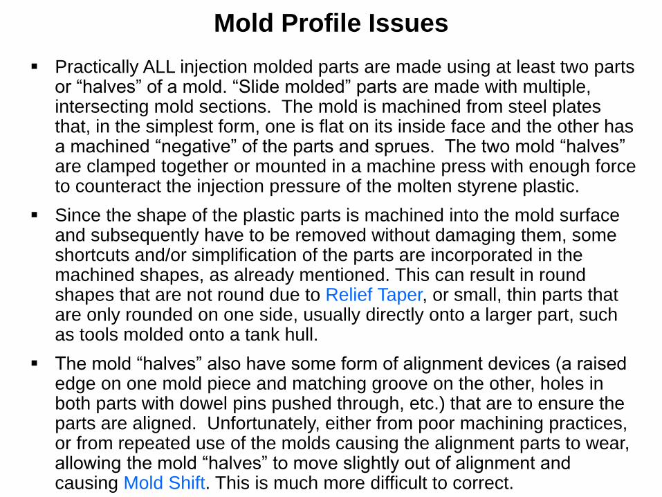
Mold Profile Issues
Practically ALL injection molded parts are made using at least two parts or “halves” of a mold. “Slide molded” parts are made with multiple, intersecting mold sections. The mold is machined from steel plates that, in the simplest form, one is flat on its inside face and the other has a machined “negative” of the parts and sprues. The two mold “halves” are clamped together or mounted in a machine press with enough force to counteract the injection pressure of the molten styrene plastic.
Since the shape of the plastic parts is machined into the mold surface and subsequently have to be removed without damaging them, some shortcuts and/or simplification of the parts are incorporated in the machined shapes, as already mentioned. This can result in round shapes that are not round due to Relief Taper, or small, thin parts that are only rounded on one side, usually directly onto a larger part, such as tools molded onto a tank hull.
The mold “halves” also have some form of alignment devices (a raised edge on one mold piece and matching groove on the other, holes in both parts with dowel pins pushed through, etc.) that are to ensure the parts are aligned. Unfortunately, either from poor machining practices, or from repeated use of the molds causing the alignment parts to wear, allowing the mold “halves” to move slightly out of alignment and causing Mold Shift. This is much more difficult to correct.

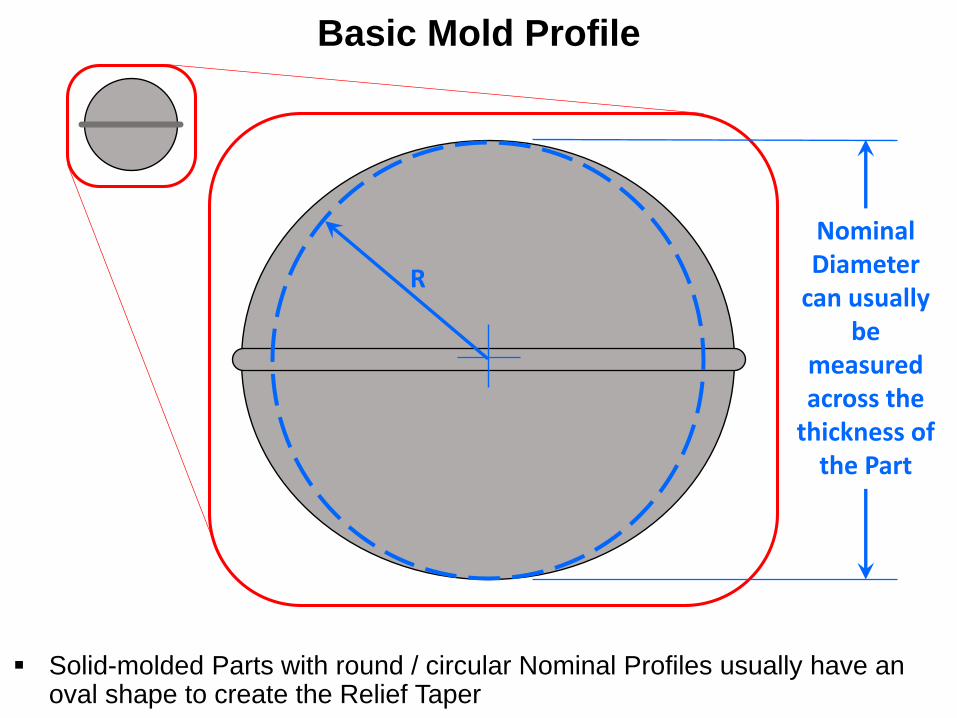
Basic Mold Profile
Sometimes the best strategy is to trim away Mold Over Shift on one side to retain as much of the Nominal Dimension accepting the residual shape error
Mold Shift
Basic Mold Profile
Solid-molded Parts with round / circular Nominal Profiles usually have an oval shape to create the Relief Taper
R
Nominal Diameter
can usually be
measured across the
thickness of the Part
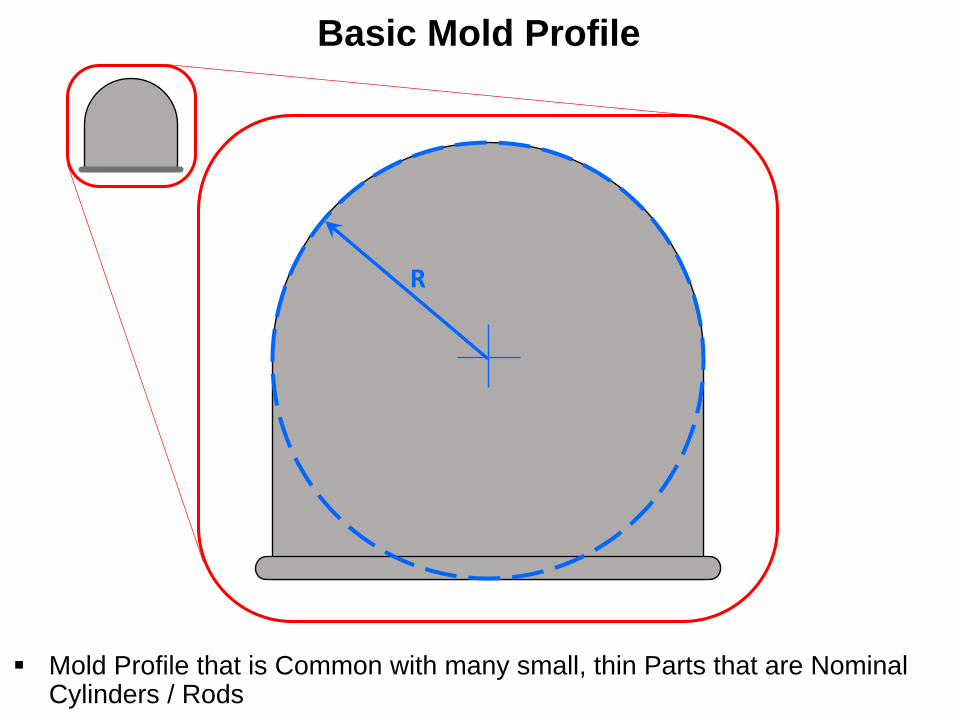
Basic Mold Profile
Mold Profile that is Common with many small, thin Parts that are Nominal Cylinders / Rods
R

Basic Mold Profile
Usually Parts with Round / Circular Profiles which have Mold Shift issues can be trimmed to preserve both the Nominal Dimension and Shape
R
Nominal Diameter
can usually be
measured across the
thickness of the Part
Mold Shift

Techniques and Methods for Removing Mold Seams
A. Cut, Carve, and Trim with a No.11 Blade.
B. Shave and Scrape with a No.11 Blade.
C. File using Needle Files or Bore with Reamers.
D. Use Saws like Broaches to Remove Seams in Tight Grooves.
E. Sanding using Sanding Block (flat and sharp edges) and/or using a Flexi-File (round or curved profiles).
F. Buffing with 0000 (4x0) Steel Wool to Remove Tooling Marks.

Techniques and Methods for Removing Mold Seams
A. Cut, Carve, and Trim with a No.11 Blade
Use this method to remove large amounts of material quickly and to roughly reshape profiles by leveling Relief Tapers and Mold Shifts.
Use the very tip of the blade to reach tight areas and to carve into small radius areas. The closer to the tip of the blade the tighter the radius that the knife can cut without “chattering.”
Useful technique to remove large amounts of Flash.
Be careful not to cut too deeply and note that on curves the edges of the knife cuts will leave sharp lines.

Techniques and Methods for Removing Mold Seams
B. Shave and Scrape with a No.11 Blade
For shaving, tilt the knife blade at an angle to the surface of the work and draw or push it along the surface in the direction of the tilt.
Scraping with the edge or the back of the blade will remove small amounts of material by shaving the surface leaving the work surface very smooth.
Note that on curved or radiused surfaces, the scraping action can leave lines.
To avoid creating flat spots on curves, scrape in a spiraling direction across the long axis of the curve and continuously move the knife to new areas. Scrape back & forth along
the material to be removed

Techniques and Methods for Removing Mold Seams
C. File using Needle Files or Bore with Reamers
Filing is useful for shaping or reshaping the profiles of the parts, leveling out Relief Tapers, sharpening edges and corners, or restoring shapes that have been mis-molded or over-tooled when removing the Mold Seams.
Files, even the smallest and finest, will leave tooling marks (usually series of lines and grooves) that must be cleaned up.
Tapered Micro-Reamers are the best tools to remove Relief Tapers and Mold Seams on the insides of small holes. Insert the reamer from the Mold Seam side and use the taper of the reamer to level out the Relief Taper. Reamers are faster and give more control than using drills.

Techniques and Methods for Removing Mold Seams
D. Using Saws like Broaches to remove Seams in Tight Grooves
Filing is useful for shaping or reshaping the profiles of the parts, leveling out Relief Tapers, sharpening edges and corners, or restoring shapes that have been mis-molded or over-tooled when removing the Mold Seams.
A broach is a machine tool that is used to create grooves and channels. It is NOT a drill bit even though they look similar. They generally appear like short, but large saw blades that have only a few teeth (without any “set”). Most Broaches only cut in one direction. You can use a short piece of broken Jeweler’s Saw Blade.
For Dentistry, Broaches are round, tapered flexible steel “wire” that is either a twisted into cutting ridges or have barbs to cut material. Like Drill Bits, they are made in various sizes, but since they taper, you wont need as many different sizes.

Techniques and Methods for Removing Mold Seams
D. Using Saws like Broaches to remove Seams in Tight Grooves (continued)
You can use a fine saw in the same manner to remove mold seams that go across grooves and thin channels on parts that are too small to cut into with a knife.
You will have more control if you orient the saw blade so that you cut as you draw the blade towards you rather than when pushing away.
Note that on parts with round profiles, using a round Dental Broach will give you a better appearance, but you can also use a square broach by twisting the part as you draw the saw blade across the mold seams.
A saw can also be used to “square up” and sharpen inside angles as you remove mold seams in them.
Mold Line/Flash
Draw the Broach across
the Mold Lines (rotating
the part will give a more
uniform shape)
Mold Line/Flash

Techniques and Methods for Removing Mold Seams
E. Using a Sanding Block (flat & sharp edges)…
Nothing works better than a sanding block to level and “square up” large flat areas or edge profiles to eliminate relief tapers. Sanding sticks or blocks with hard cores are better than the ones made with a foam board core, which can “round” a flat surface if too much pressure is used.
400 grit wet-or-dry sand paper gives a good compromise between removing a lot of material quickly without leaving deep sanding marks.

Techniques and Methods for Removing Mold Seams
E. … And/or using a Flexi-File (round or curved profiles) (continued)
A Flexi-File is the ideal tool for sanding round or curved profiles. The 320 grit strips remove material quickly without leaving deep marks.
Flexi-File strips can be cut lengthwise to make thin strips for small areas. Also, one end of the strip can be threaded through the work to sand seams on the insides of openings.

Techniques and Methods for Removing Mold Seams
F. Buffing with 0000 (4x0) Steel Wool to remove Tooling Marks
Buffing the areas of the parts that have been worked to remove mold seams and sprue attachment paints will remove the tooling marks left from using the other methods.
Be careful to not be too aggressive using this method. It will soften and even obliterate small molded on details and round over edges and corners.
Aggressive buffing can also break off small molded on details.
However, this is the “crowing touch” when it comes to cleaning up injection molded parts to the shapes and dimensions intended by the kit designer.
WARNING! Steel wool is flammable and care should be
used when working with it around any open flame source.

Sunken Ejector
Pin Mark
Raised Ejector
Pin Mark
Ejector Pin Marks result from
the Mechanical Pins that push
the parts/sprues from the Mold
Techniques and Methods for Removing Ejector Pin Marks
Note: If a Model is engineered well,
the Ejector Pin Marks will be located
on parts so that they will not be
visible once the model is assembled

Techniques and Methods for Removing Ejector Pin Marks
A. Raised Ejector Pin Marks
Can be removed by cutting, scraping and sanding.
Be careful of nearby raised details such as rivets, bolts, weld beads, etc. that can be easily damaged.
Sometimes some filler is need because the plastic around the raised pin mark has shrunk causing a slight circular depression that remains even after the raised pin mark has been removed.

Techniques and Methods for Removing Ejector Pin Marks
B. Sunken Ejector Pin Marks
Usually must be filled and then sanded smooth. Buff with steel wool to eliminate sanding marks.
However, sometimes very shallow pin marks can be scraped and sanded to blend them into the surrounding area.
Shallow marks can be filled using polyester putty (Squadron Green Stuff, 3M Acryl Red or Blue, WhiteOut, Mr. Surfacer, etc). However, filler shrinkage can often make the ejector pin mark visible again. Other fillers can also be used, such as 2-part epoxy putty or CA with micro-balloons or baking soda, but subsequent sanding to smooth them out can be problematic since these fillers can often become harder than the surrounding plastic.

Techniques and Methods for Removing Ejector Pin Marks
B. Sunken Ejector Pin Marks (continued)
Punched styrene plastic disks can be glued into deeper sunken marks to reduce the amount of filler needed, thus mitigating the filler shrinkage issue. Allow styrene cement, if used, to dry completely to mitigate shrinkage that can make the mark visible later. If CA glue is used, sand it out as soon as it sets.

Techniques and Methods for Removing Ejector Pin Marks
C. Expedient Sanding Tools
Oftentimes, Expedient Sanding Tools will be needed to reach into recessed part areas or areas that have surrounding molded on details.
Useful tools can be made from small strips, squares or disks of sand paper glued to dowels or pieces of sprue with a contact cement (i.e. Walther’s Goo, etc). Even small pieces of sanding paper glued to the end of a tooth pick can be useful.
Cut piece of
Sand Paper
Dowel, toothpick
or sprue Cement Angled Tool Tip

Removing Sprue Attachment Points (technically, “Gates”)
Sprue Attachment Points, technically known as “Gates”, serve two purposes, hold the actual parts onto the sprue for packaging, and to allow the liquid styrene plastic to flow into the portion of the mold that makes the parts. Runners are the frame of sprues that hold everything together.
Some Gates are small and at the edge of a part, while others are bigger and can even run onto the part, requiring more effort to remove without damaging.
Runners
Gates
Part

Removing Sprue Attachment Points (technically, “Gates”)
A. Removing the Part from the Sprues.
Using Sprue Cutters, remove the Part from the sprues, leaving a portion of the Gate (i.e.; nub) next to the part so as not to accidently damage the part.
High-quality Flush Side Cutters have very sharp and precise cutters that will cut the sprue to an almost clean cut. Lower quality or dull Flush Side Cutters can pinch the sprue instead of cutting, sometimes causing twist that can damage the Part.
On some Parts you may be able to cut the Gate right next to the Part’s side, leaving just a small nub.

Removing Sprue Attachment Points (technically, “Gates”)
A. Removing the Part from the Sprues. (continued)
For small, thin Gates, a sharp Hobby Knife Blade can be used to cut a Part from the sprues, leaving a portion of the Gate (i.e.; nub) next to the part so as not to damage the part.
Some Parts may be damaged due to twisting caused by a Sprue Cutter bending/twisting the Sprue Runners, so it might be beneficial to make some saw cuts to separate the Runners and reduce the Attachment Gates to one side.
Saw Cuts In Sprue RunnerSmall Saw BladeThin Parts

Removing Sprue Attachment Points (technically, “Gates”)
A. Removing the Part from the Sprues. (continued)
Sometimes using a Sprue Cutter may not be feasible, so a Saw Blade or even a Hot Knife can be used to remove a complex or tiny Part from the sprues, leaving a portion of the Gate (i.e.; nub) next to the part so as not to damage the part.
Individual Tracks on the Sprue, Parts with a LOT of Gate attachment points, thin Stowage Basket bars, a Machine Gun with the Barrel connected to a Gate, etc., are examples of difficult to remove parts that can be easily damaged.

B. Removing the Part from the Sprues.
Once the Part is removed from the Sprue Runners, the “nibs” need to be clipped, filed, and/or sanded off without damaging the surface and details of the Part.
High-quality Sprue Cutters and other specialty Cutters can be used to remove nearly all of the “nib”, but care must be taken to not cut into the Part itself. A few light passes with a fine grit Sanding Stick should almost completely eliminate the Attachment Gate.
Polishing with an Emory Board, bit of Steel Wool, or even an old Tooth Brush should be the final touch.
Removing Sprue Attachment Points (technically, “Gates”)
“Nub” or Gate Remnant

Summary
Mold Seams, Relief Tapers and Ejector Pin Marks are all flaws caused by the injection molding manufacturing process.
These flaws must be removed in order to bring the plastic parts back to their intended shapes, profiles and nominal dimensions.
Removing these flaws improves fit and makes assembly easier.
Removing these flaws improves the appearance of the final assembly.
Contest Judges will immediately spot these flaws if they are left on your models.
If you leave these manufacturing flaws on your models, you can be assured that your builds will not make the “first cut” in any contest.