basic fill color r 100 g 160 b 200 accent 1 ”logo blue” r 0 g 39 b 118 yellow (highlight) r 252...
TRANSCRIPT

OP300
Technical training presentation
Installation

OP 300 is delivered in 2 boxes
OP 300 delivery content
BOX 1 contains- Column and carriage- Accessories- Wall bracket- Manuals
BOX 2 contains
- Main Support
- Rotating unit

Pre-installation requirements
PC minimum requirements
Windows XP Professional with SP2 (32-bit)
2.4 GHz Core 2 Duo dual core processor or equivalent
2 GB RAM
500 GB HDD or larger
Gigabit Ethernet (CAT6)
One available PCI-Express x16 bus slot for a GPU card
2 available USB ports (hardware key locks)
19" LCD display, 1280 x 1024
Time and persons
For complete installation 1 day and 2 persons are needed
Installation room
Check minimum room size from pre-sales check-list.
Physical environment specs in the pre-sales check-list.
Unit mounts to the floor and wall with mounting hardware (not supplied).
Radiation shielding
Local requirements must be met

Product dimensions
(78.9”)
Range:
54.5” to
56.1”

Installation overview
Stand up the column
Attach unit to the wall and / or to the floor
Lift the carriage and hang it on the column.
Check leveling of the unit
Connect all cables and attach exposure button
and touch panel
Carry out calibration procedure for the unit
Install and configure Cliniview
For detailed instructions please refer to Installation
manual
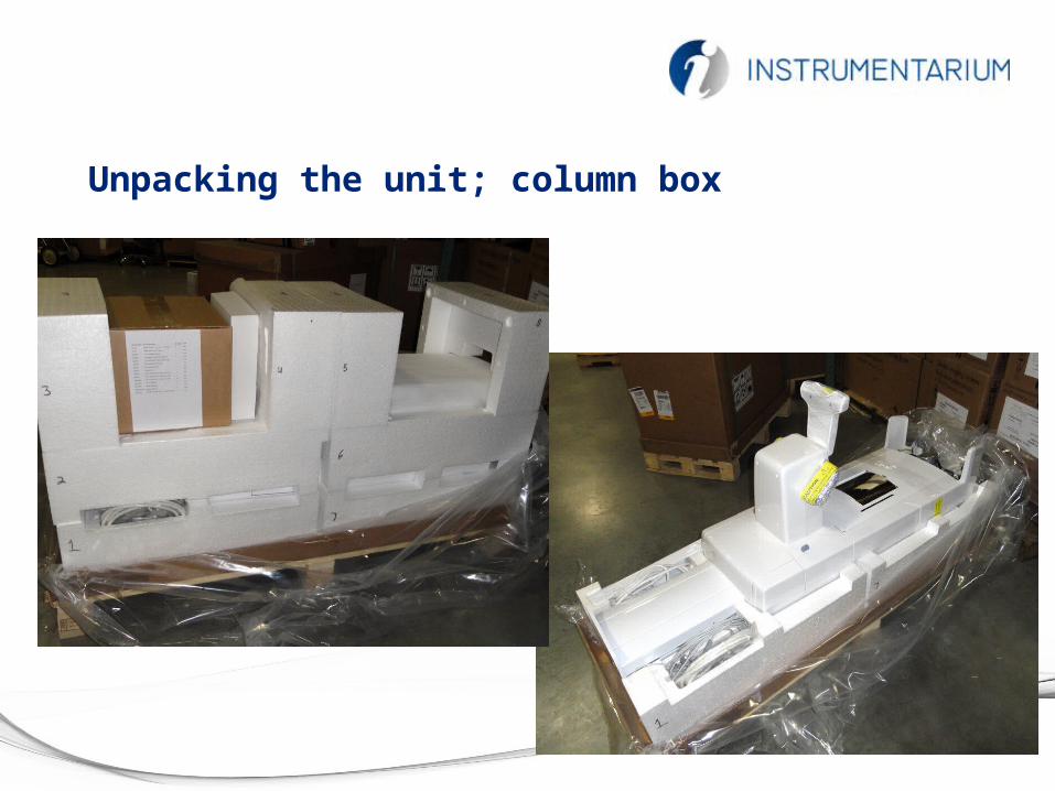
Unpacking the unit; column box

Unpacking the unit; overhead box

Stand up the column

Three mounting variations:
With one wall mounting bracket and bolting unit to the floor
With two wall mounting brackets -- no floor drilling is needed
Note: Base plate and second wall mounting bracket has to be ordered separately
With one wall mounting bracket
and base plate
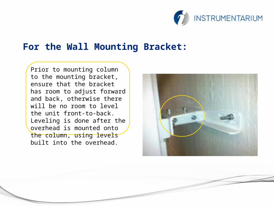
For the Wall Mounting Bracket:
Prior to mounting column to the mounting bracket, ensure that the bracket has room to adjust forward and back, otherwise there will be no room to level the unit front-to-back. Leveling is done after the overhead is mounted onto the column, using levels built into the overhead.
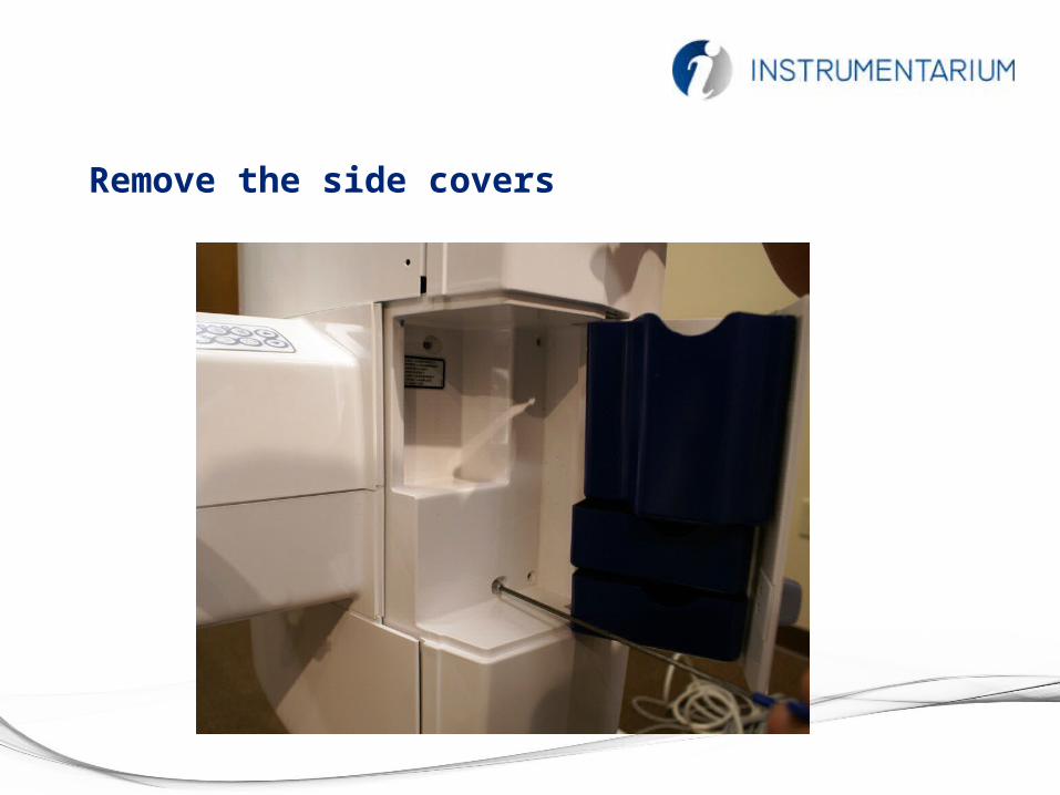
Remove the side covers

Cut the foam, leave the foam banded onto the overhead

Prepare for the overhead

Slide the overhead onto the column

Pins align the overhead prior to fixing with the bolts
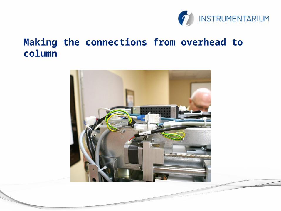
Making the connections from overhead to column

Connections, continued

Connections, continued

Mains power, handswitch and Ethernet connections

Remote handswitch terminals

Remove the packing foam

Remove the plywood

Remove the brackets

Configure the rotation stop
• Remove rotation stop bracket• Rotate the tubearm 90 degrees CCW, as seen from above• Reinstall rotation stop bracket

Level the unit
• Levels located in overhead• Use column bracket to set level

Configuring the mains power jumpers
• Default 220V configuration• 100V, 115V jumpers stored on side panel

Install and Wire the GUI

Set the column height microswitch

Install the side covers
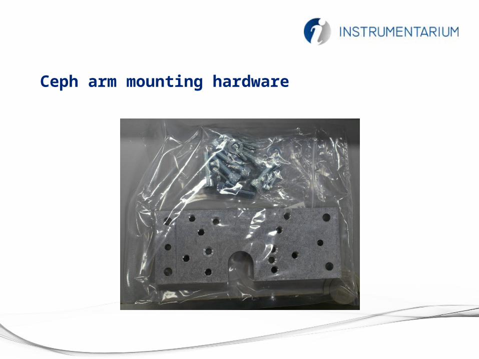
Ceph arm mounting hardware

Ceph arm mounting brackets

Ceph head packaging

Mounting the ceph head

Level the ceph head

Ceph head connections

Ceph head connections, continued

Host computer video card
• Reconstruction video card packed in column box•Open host computer, remove old video card from PCI slot (A)•Locate “Y” power adapter (B)•Install “Y” power adapter (C)•Plug in reconstruction video card•Ensure that two power plugs are connected to video card (D)•Locate reconstruction dongle, plug into available USB port on the host computer
A
B
C
D

Powering on the unit

“Push any button” to initialize the unit

Configure the host computer’s NIC

Launch Cliniview Software

Configure Driver
• Left-ctrl/right click on driver icon to open the driver setup script•Enter the IP address of the unit to be controlled

Launch S2 Terminal

Calibration of the unit
How to start:
Patient record must be active- select in the control panel- select “Service” in the control panel-check to see if any items have red exclamation points on them – those items must be recalibrated

Alignment and QA Tools
Pan alignment cone assembly
QA Phantom CT Geometry tool
Leveling base

Acceptance limits
Passed
Calibration program is successfully done.
Move on to next calibration.
Not passed
Adjustment is still needed. Follow the instructions the image (if any) and take another exposure. Some calibration programs are iterative and demands a few repetitions.
Failed
System could not decide what adjustment should be done in order for the calibration to succeed. This calibration status is always the result of some error condition. Taking another exposure will not help. The image may give a hint on what the problem is (e.g. no radiation, collimator severely tilted, image data corrupted…).

Pan geometry calibration
Purpose:
Panoramic geometry position calibration
Acceptance limits:
Passed / Not passed / Failed
GUI informs if calibration has passed

CT Geometry calibration
Purpose:
Calibrates ct geometry, needed only with 3D units
Acceptance limits:
Passed / Not passed / Failed
GUI informs if calibration has passed
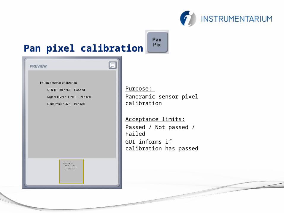
Pan pixel calibration
Purpose:
Panoramic sensor pixel calibration
Acceptance limits:
Passed / Not passed / Failed
GUI informs if calibration has passed
Pan pixel calibration

CT pixel calibration
Purpose:
Performing pixel gain and dead pixel correction
Acceptance limits:
Passed / Not passed / Failed
GUI informs when calibration is passed

Other calibration items
Confidential, for distributors only 51
• Perform full calibration if red exclamation points are found on calibration screen•Full calibration if ceph arm is added•Use S2 service mode command “indicator service clear” to reset calibration period

Install the rear cover