basic electronics for the new ham (outline) electronics course-kit/basic... · basic electronics...
TRANSCRIPT

Basic Electronics

Basic Electronics Course Standard Parts List Quantity Part Description Part Number 1 Multimeter SNT-818 1 Solderless Breadboard ZY-201 1 Jumper Wires* 1 9V Battery Holder 1 1.5V Battery Holder 1 100 ohm ** 1 200 ohm 1 330 ohm 2 1000 ohm 1 2.2K ohm 2 4.7k ohm 1 10K ohm 1 100K ohm 1 100uF Electrolytic Cap 1 Diode 1N914 1 Zener Diode 1N4732A 1 Transistor 2N3604 1 LED LH2040 * More jumpers than needed for one student, can be shared to reduce costs ** Individual components are often sold is quantity, quantity purchase can be shared between students to reduce costs.

Basic Electronics for the New Ham (Outline)
• The Elements of Electricity • Volt-Ohm-Meter Basics (Measuring Electricity) • Circuit Diagrams Basics (Electronic Roadmaps) • The Resistor • Ohm’s Law • The Capacitor • The Inductor • The Diode • The Transistor (Electronic Valve)

The Elements of Electricity
• Voltage • Current • Resistance • Types of Current: AC and DC • Circuits
– Closed – Open – Short

Voltage, Current, and Resistance • Water flowing through a
hose is a good way to imagine electricity
Water is like Electrons in a wire (flowing electrons are called Current)
Pressure is the force pushing water through a hose – Voltage is the force pushing electrons through a wire
Friction against the holes walls slows the flow of water – Resistance is an impediment that slows the flow of electrons

Forms of Current
• There are 2 types of current – The form is determined by the directions the
current flows through a conductor • Direct Current (DC)
– Flows in only one direction from negative toward positive pole of source
• Alternating Current (AC) – Flows back and forth because the poles of the
source alternate between positive and negative

AC Current Vocabulary
Time Period of One Cycle
http://n5dux.com/ham/scholarship/

Circuits
• A circuit is a path for current to flow • Three basic kinds of circuits
– Open – the path is broken and interrupts current flow
– Closed – the path is complete and current flows were it is intended
– Short – an unintended low resistance path that divers current

Circuits

Volt-Ohm-Meter (VOM) Basics (Measuring Electricity)
• Common Functions • Voltage
• AC/DC • Ranges
• Current • AC/DC • Ranges
• Resistance (DC only) • Ranges • Continuity
• Semi-conductor Performance • Transistors • Diodes
• Capacitance
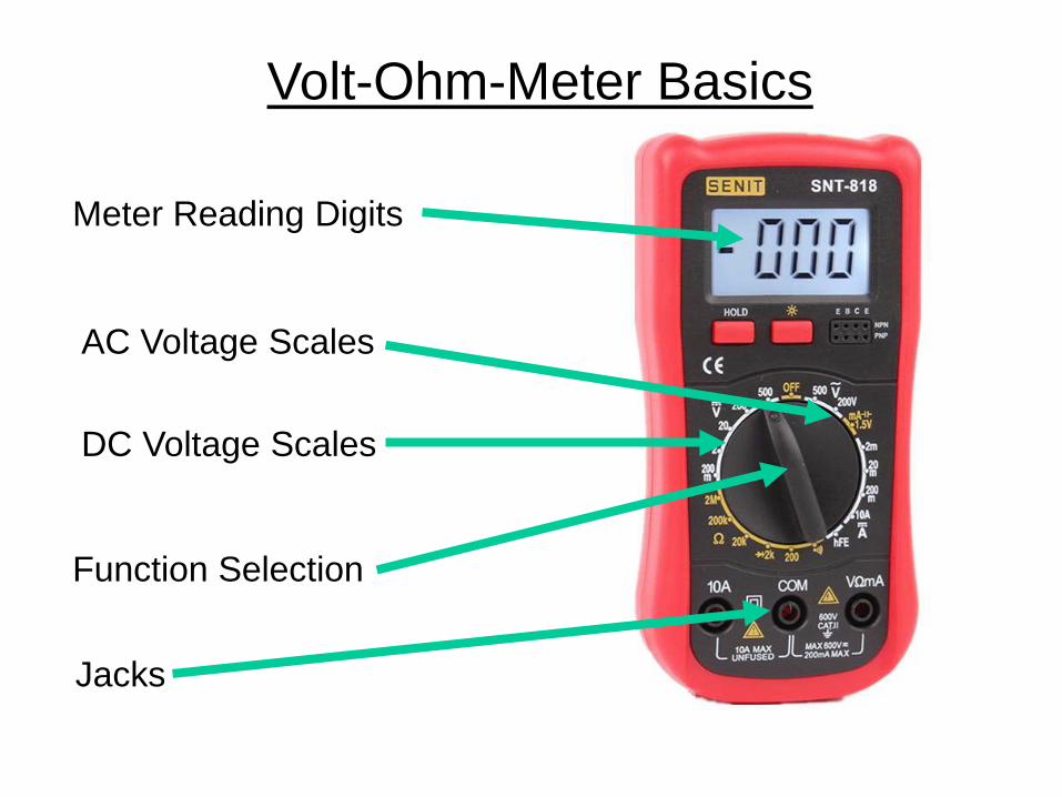
Volt-Ohm-Meter Basics
Meter Reading Digits
DC Voltage Scales
AC Voltage Scales
Jacks
Function Selection

Volt-Ohm-Meter Basics
Resistance
DC Current (low)
DC Current (high)
Transistor Checker
Diode Checker

Volt-Ohm-Meter Basics (Measuring Electricity)
• Measuring voltage • Voltage type • Scaling • Safety
• Physical (personal) • Equipment
• Measuring current • Current type • Scaling • Safety
• Physical (personal) • Equipment
• Measuring resistance • Scaling
Measuring Voltage - Safety
• When measuring voltage, the voltage being measured is exposed to the operator and flowing through the probes. Be cautious, be attentive, watch what you touch!
• The probes have sharp points so that you can make precise contacts. Use the protective shields when probes not in use.
• Observe the meter maximum limits for voltage and current. Fuses are a last resort protection feature. If you blow a fuse, you made a mistake!
Measuring Voltage • Voltage type – DC and AC
• When measuring voltage, the meter probes are placed across the voltage source.
• The VOM uses two separate functions and ranges to measure DC and AC.
• Because AC is a constantly changing wave form, measuring AC voltages is not a simple matter.
• This VOM measures pseudo-Root Mean Square (RMS) voltages

Measuring Voltage
• Meter Set-up • Scale set to
highest • Probes into right
jacks • Note voltage
polarity +

Measuring Voltage
• Select 9-volt battery • Set-up VOM on 500V DC
Scale • Touch red probe to (+) • Touch black probe to (–) • Read voltage to nearest 1
volt

Measuring Voltage
• Now touch the red probe to (-)
• Touch the black probe to (+)
• Read voltage to nearest 1 volt, note the minus sign that signifies a negative voltage

Measuring Voltage
• Set-up VOM on 200V DC Scale
• Touch red probe to (+) • Touch black probe to (–) • Read voltage to nearest
0.1 volt
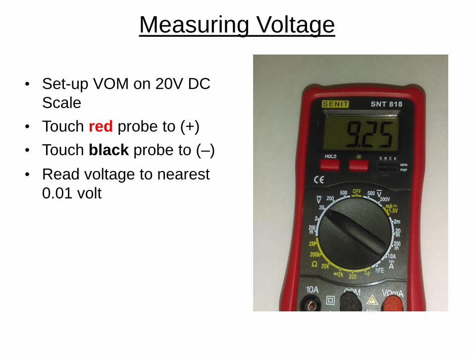
Measuring Voltage
• Set-up VOM on 20V DC Scale
• Touch red probe to (+) • Touch black probe to (–) • Read voltage to nearest
0.01 volt
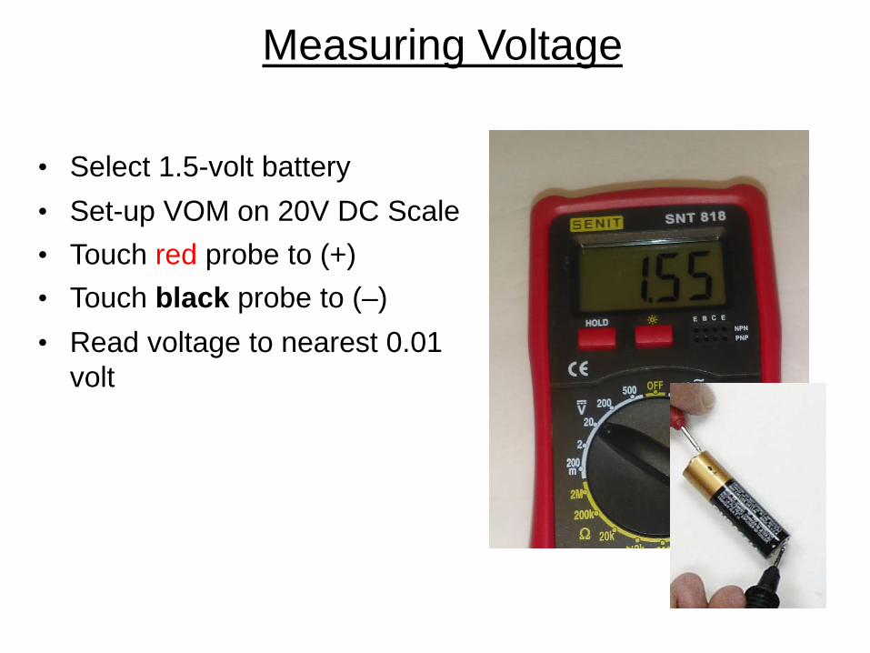
Measuring Voltage
• Select 1.5-volt battery • Set-up VOM on 20V DC Scale • Touch red probe to (+) • Touch black probe to (–) • Read voltage to nearest 0.01
volt

Measuring Voltage
• Set-up VOM on 2VDC Scale
• Touch red probe to (+) • Touch black probe to (–) • Using a 1.5 volt battery -
read voltage to nearest 0.001 volt

Measuring Voltage
• Set-up VOM on 2V DC Scale
• Touch red probe to (+) • Touch black probe to (–) • Using a 9 volt battery • This is clearly an over-
voltage situation, note the reading.
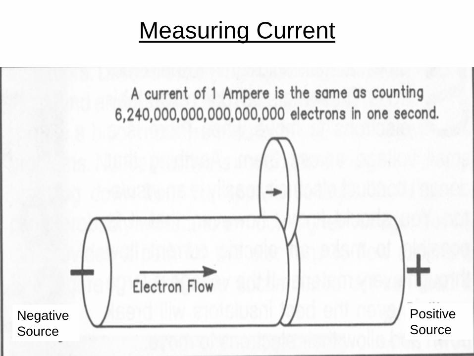
Measuring Current
NegativeSource
Positive Source

Measuring Current
• There is a greater potential for meter damage when measuring current than with any other function.
• Just as in voltage, there are two kinds of current associated with the voltage, AC and DC.
• This meter will only measure DC current, more expensive meters will measure both currents.
• To measure current, the VOM must be inserted into the circuit so that the current flows through the meter.

Measuring Current • There are two current ranges, high – up to 10 amps,
and low – 200 milliamps (0.2 amps) and below. • Internal fuses provide some meter protection for over
current situations. – Because there is such a wide range between the
current scales, there are two physical probe jacks for the two ranges
– This allows for better protection, a hardy fuse to handle up to 10 amps of current and a more fragile fuse to protect the sensitive circuits needed to measure small currents.
– Don’t count on the fuses to protect the meter!

Measuring Current
• CAUTION!!!!!!! There must be some resistance in the circuit or the current flow through the circuit will be the maximum the source will produce, AND THIS CURRENT LEVEL COULD DAMAGE THE VOM!
• In other words, DO NOT CONNECT THE VOM
PROBES DIRECTLY ACROSS THE BATTERY POLES IN THE CURRENT MEASURMENT FUNCTION!

Measuring Current
• We will be demonstrating some concepts during the current measurement exercises that will be covered in more detail later, so be patient, it will all come together in the end.
• In the following exercises you will use various
resistors to limit the current flow in a simple circuit.

The Proto Board
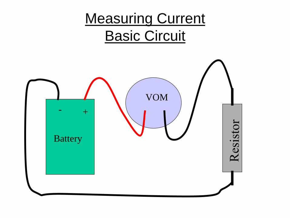
Measuring Current Basic Circuit
Battery
VOM + -

First Current Measurement • Set up the circuit using
a 100 ohm resistor (brown, black, brown).
• Connect a wire to the + power source, connect another wire to the top end of the resistor (the non grounded end).
• Set VOM current scale to 200 m. (m here is short for mA)
• Without connecting the battery, practice touching the VOM probes to the exposed wire ends.

First Current Measurement
• Connect the battery. • With the VOM set to
the 200 m current scale, touch the black lead to the wire hooked to the top side of the resistor.
• Touch the red lead to the lead coming from the + side of the battery.
• Note the VOM reading.

First Current Measurement
Now reverse the VOM leads and note the reading.

First Current Measurement
• Return the VOM leads so that the red is connected to the battery.
• Change the VOM current ranges down and note the display readings
• What is the best range for measuring the current from a 9 volt source through a 100 ohm resistor?
200 m Range
20 m Range
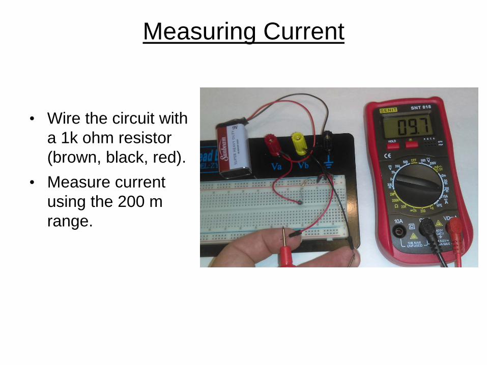
Measuring Current
• Wire the circuit with a 1k ohm resistor (brown, black, red).
• Measure current using the 200 m range.

Measuring Current
• What is the best range to measure the current through a 1 k-ohm resistor?
200 m
20 m
2m

Measuring Current
• Wire the circuit with a 10 k-ohm resistor (brown, black, orange).
• Measure current with the 2m range.

Measuring Current
• What is the best range to use to measure the current through a 10 k-ohm resistor at 9 volts?
2m
200 u

Measuring Current • Wire the circuit with a
100 k-ohm resistor (brown, black, yellow).
• Begin with the 200 m range, and measure the current at each range.
• What is the best range to use to measure the current trough a 100 k-ohm resistor at 9-volts?
200m
20m
2m
Measuring Resistance
• When the VOM is used to measure resistance, what actually is measured is a small current applied to the component.
• There are 5 ranges. An out of resistance reading will be indicated by a single “1 ” digit. Remember ‘k’ means multiply the reading by 1000.
• Operating voltages should be removed from the component under test or you could damage the VOM at worst, or the reading could be in error at best.

Measuring Resistance • Disconnect the
battery from the board, remember to measure resistance with the circuit un-powered.
• Put the 100 ohm resistor in place, no additional wires are required.
• Select the 200 ohm range and touch the probe leads to both sides of the resistor.

Measuring Resistance
Now reverse the probe leads and observe the reading.
Any difference?

Measuring Resistance • Now using the 100 ohm
resistor, measure the resistance using each of the other ranges.
• Note that the resolution of the reading decreases as the maximum ohm reading increases, down to the point where it is difficult to get a useful resistance reading.
2k ohm
20 k-ohm
200 k-ohm
2M ohm

Measuring Resistance
• Now use the 1k ohm resistor and the 200 range.
• Explain the reading you observe.
• Find the appropriate range to measure 1,000 ohms (1 k-ohm).
200
2k

Measuring Resistance
• Now use the 10 k-ohm and the 100 k-ohm resistor. • First determine the appropriate range to use for each
resistor. • Second make the resistance measurements • Third, using higher ranges, predict the reading and
confirm your prediction by taking the measurements

Measuring Resistance
• Just for fun, use the VOM to measure the resistance offered between different body parts. – The voltage and current used by the VOM is not
dangerous. • Discuss your observations and how your
measurement techniques could influence the readings you get from the VOM.
Circuit Diagrams Basics (Electronic Roadmaps)
• Component Representations – Resistor – Ground – Capacitor – Inductor – Diode – Transistor – Integrated circuit – Special
Circuit Diagrams Basics
Vcc1
Gnd8
GP52
GP07
GP43
GP16
GP34
GP25
12F675
Out
Gnd
Vcc
4.7K
SW5N.O.
78L05+9V
Out
Gnd In
.1uF
SW6
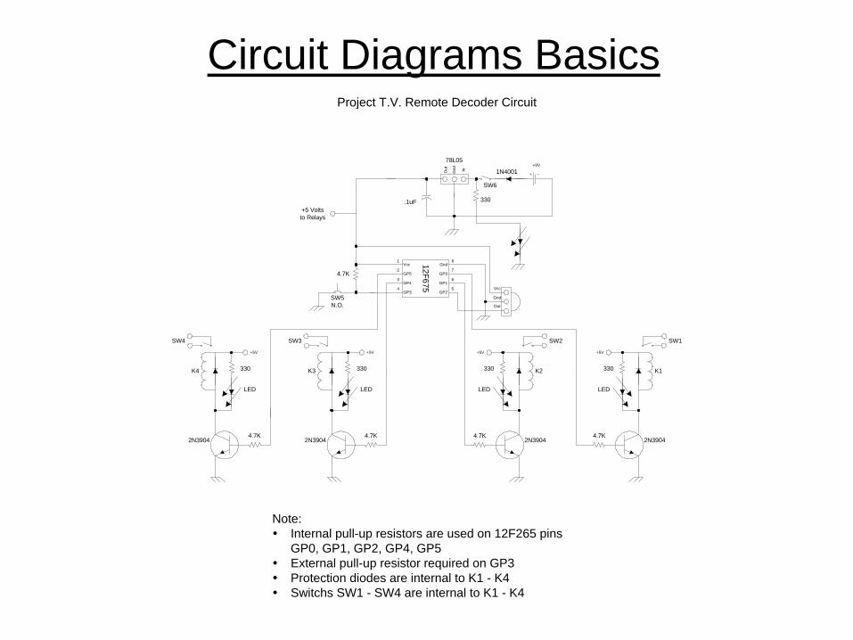
Note: Internal pull-up resistors are used on 12F265 pins
GP0, GP1, GP2, GP4, GP5 External pull-up resistor required on GP3 Protection diodes are internal to K1 - K4 Switchs SW1 - SW4 are internal to K1 - K4
Project T.V. Remote Decoder Circuit
330
1N4001
+5 Voltsto Relays
330
2N3904
+5V
K1
SW1
LED
4.7K
330
2N3904
+5V
K2
SW2
LED
4.7K
330
2N3904
+5V
K3
SW3
LED
4.7K
330
2N3904
+5V
K4
SW4
LED
4.7K

Resistor
Fixed Variable

Ground
Earth Chassis
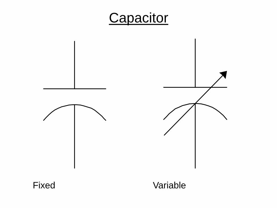
Capacitor
Fixed Variable

Inductor
Air Core Iron Core Variable
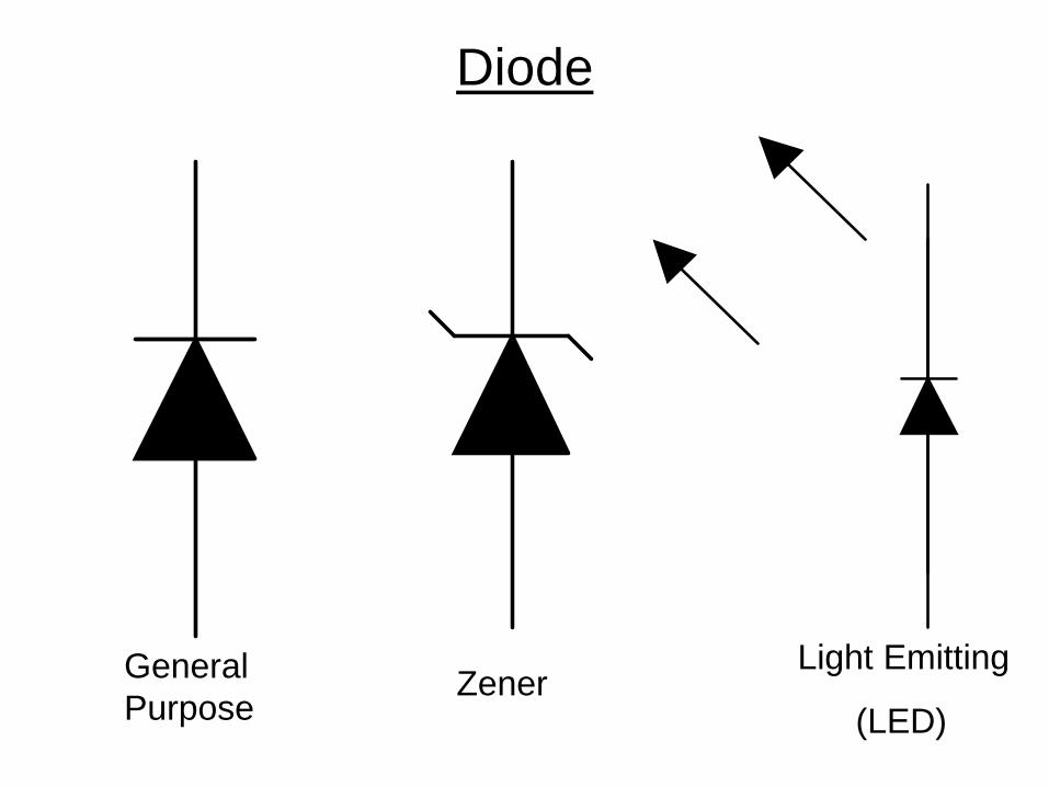
Diode
General Purpose
Zener Light Emitting
(LED)

Transistor
NPN PNP FET
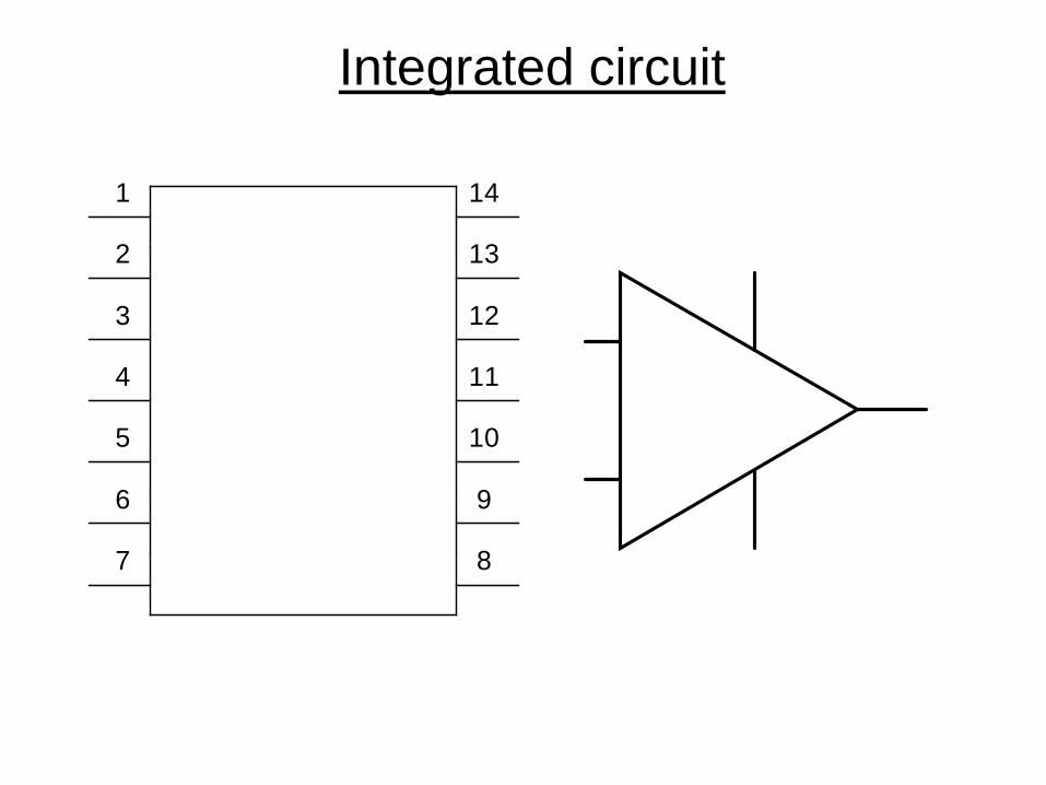
Integrated circuit
2
3
4
5
13
12
11
10
7 8
1 14
6 9
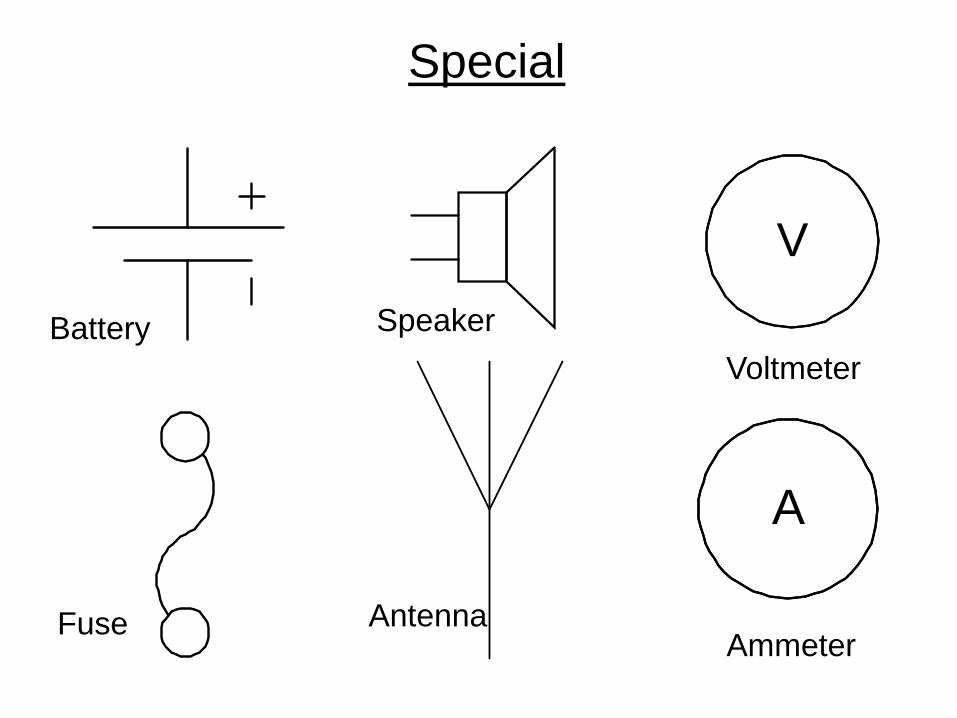
Special
V
A
Battery Speaker Voltmeter
Ammeter Antenna Fuse

The Resistor
• Resistance defined • Resistance values
– Ohms – color code interpretation – Power dissipation
• Resistors in circuits – Series – Parallel – Combination
Resistance Defined
• Resistance is the impediment to the flow of electrons through a conductor – (friction to moving electrons) – Where there’s friction, there is heat generated – All materials exhibit some resistance, even the
best of conductors
• Unit measured in Ohm(s) – From 1/10 of Ohms to millions of Ohms

Resistor Types
• Fixed Value • Variable value • Composite resistive material • Wire-wound • Two parameters associated with resistors
– Resistance value in Ohms – Power handling capabilities in watts

All 1000 Ohm Resistors
1/8 ¼ ½ 1 2 20

Resistor Types

Resistor Types
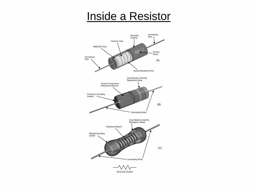
Inside a Resistor
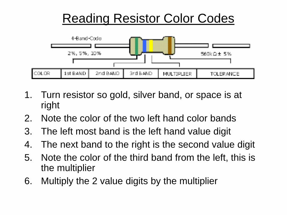
Reading Resistor Color Codes
1. Turn resistor so gold, silver band, or space is at right
2. Note the color of the two left hand color bands 3. The left most band is the left hand value digit 4. The next band to the right is the second value digit 5. Note the color of the third band from the left, this is
the multiplier 6. Multiply the 2 value digits by the multiplier

Reading Resistor Color Codes

Reading Resistor Color Codes (Practice Problems)
1. Orange, orange, red? 2. Yellow, violet, orange? 3. Brown, black, brown? 4. Brown, black, green? 5. Red, red, red? 6. Blue, gray, orange? 7. Orange, white, orange?
Power dissipation
• Resistance generates heat and the component must be able to dissipate this heat to prevent damage.
• Physical size (the surface area available to dissipate heat) is a good indicator of how much heat (power) a resistor can handle
• Measured in watts • Common values ¼, ½, 1, 5, 10 etc.

Resistors in Circuits Series
• Looking at the current path, if there is only one path, the components are in series.

Resistors in Circuits Series
RE=R1+R2+Rn
Resistors in Circuits Series
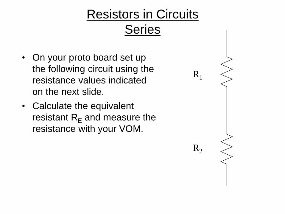
• On your proto board set up the following circuit using the resistance values indicated on the next slide.
• Calculate the equivalent resistant RE and measure the resistance with your VOM.
R1
R2

Resistors in Circuits Series
R1 R2 Calculated RE
Measured RE
100 100
100K 10K
4.7K 4.7K
330 4.7K
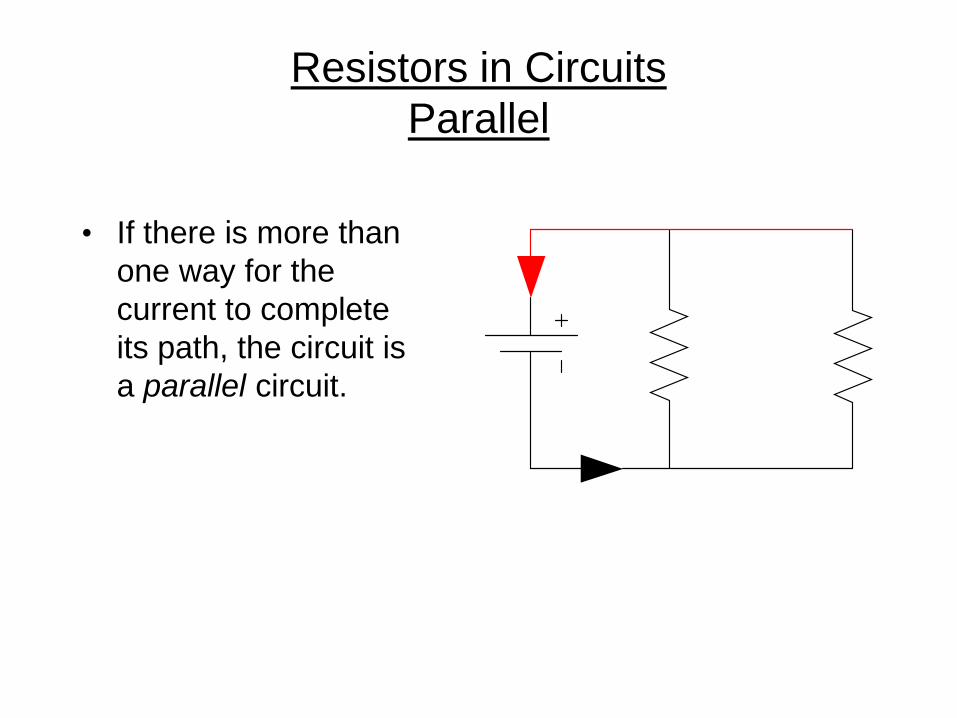
Resistors in Circuits Parallel
• If there is more than one way for the current to complete its path, the circuit is a parallel circuit.

Resistors in Circuits Parallel
RE=R1 R2
R1+R2= 1
1R1
+ 1R2
+ 1Rn
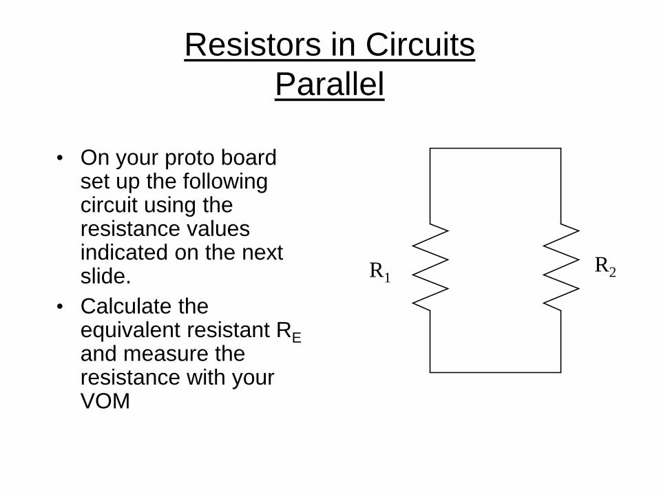
Resistors in Circuits Parallel
• On your proto board set up the following circuit using the resistance values indicated on the next slide.
• Calculate the equivalent resistant RE and measure the resistance with your VOM
R1 R2

Resistors in Circuits Parallel
R1 R2 Calculated RE
Measured RE
100 100
100K 10K
4.7K 10K
330 4.7K

Resistors in Circuits Parallel Challenge
• Make a circuit with 3 resistors in parallel, calculate the equivalent resistance then measure it. R1 = 330 ohm R2 = 10 k-ohm R3 = 4.7 k-ohm
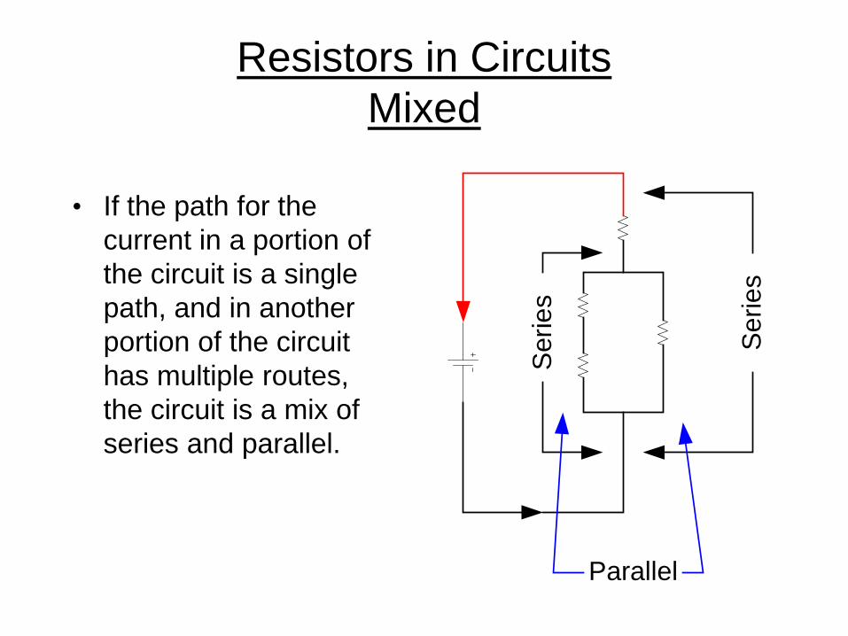
Resistors in Circuits Mixed
• If the path for the current in a portion of the circuit is a single path, and in another portion of the circuit has multiple routes, the circuit is a mix of series and parallel.
Ser
ies
Ser
ies
Parallel

Resistors in Circuits Mixed
• Let’s start with a relatively simple mixed circuit. Build this using: R1 = 330 R2 = 4.7K R3 = 2.2K
R1
R2 R3
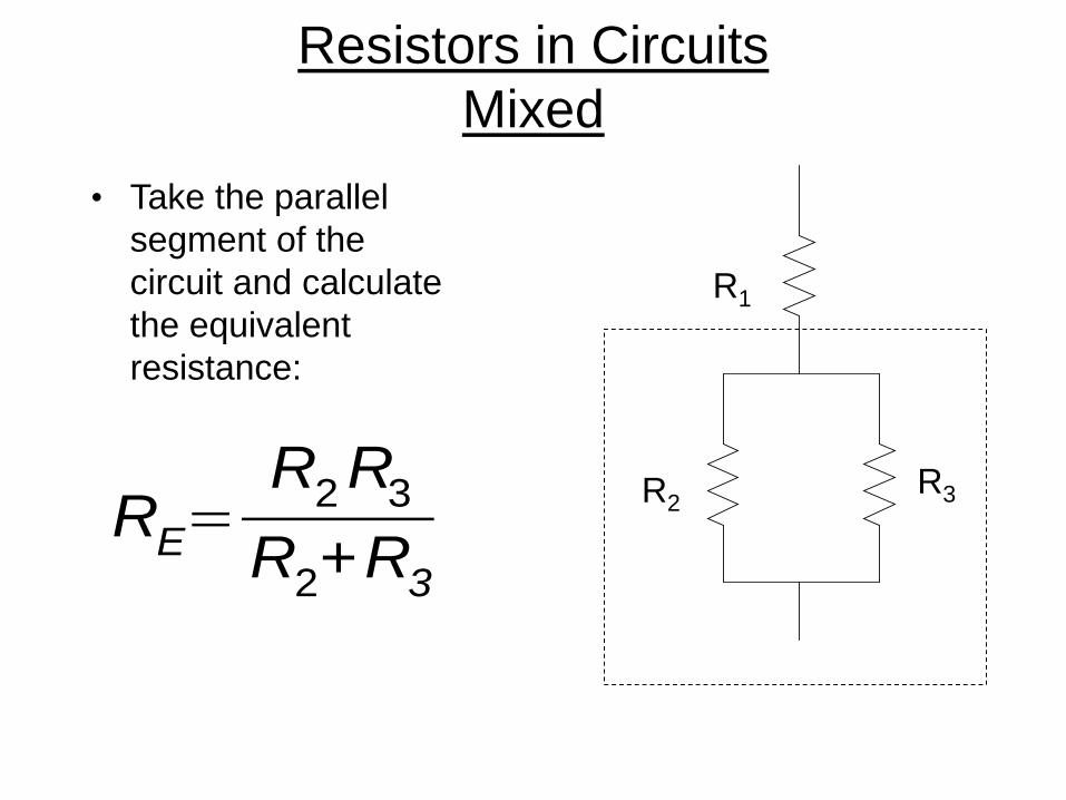
Resistors in Circuits Mixed
• Take the parallel segment of the circuit and calculate the equivalent resistance:
R1
R2 R3 RE=
R2 R3
R2+R3

Resistors in Circuits Mixed
• We now can look at the simplified circuit as shown here. The parallel resistors have been replaced by a single resistor with a value of 1498 ohms.
• Calculate the resistance of this series circuit:
R1+RE
R1
RE=1498

Resistors in Circuits Mixed
• In this problem, divide the problem into sections, solve each section and then combine them all back into the whole.
• R1 = 330 • R2 = 1K • R3 = 2.2K • R4 = 4.7K
Serie
s
Par
alle
l
Serie
s
R1
R2
R3
R4

Resistors in Circuits Mixed
• Looking at this portion of the circuit, the resistors are in series. R2 = 1k-ohm R3 = 2.2 k-ohm
R2
R3
RE=R2+R3
Resistors in Circuits Mixed
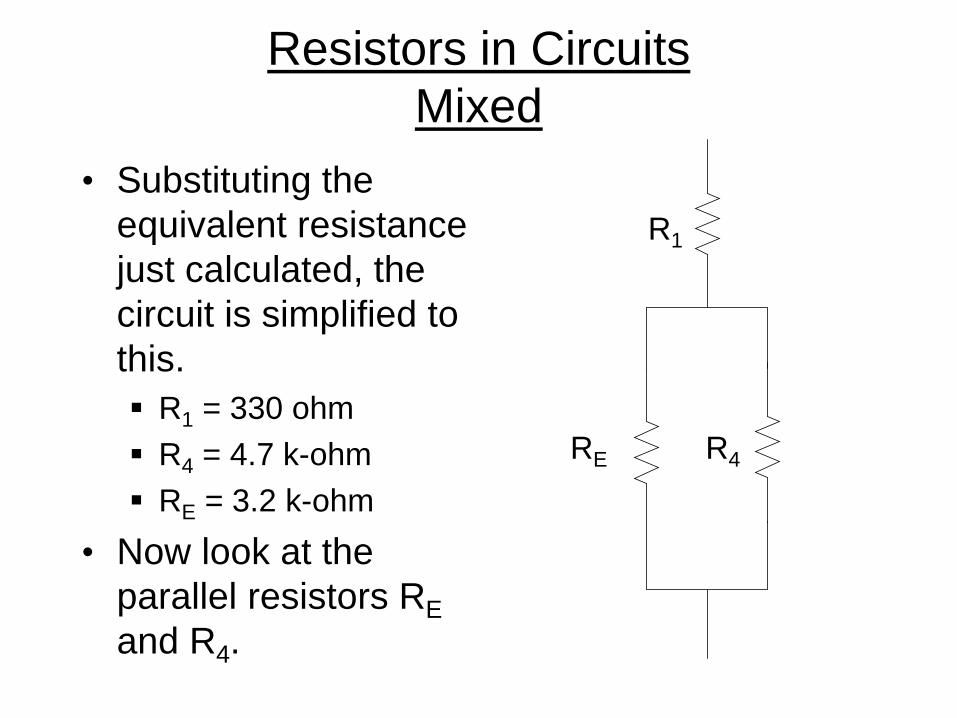
• Substituting the equivalent resistance just calculated, the circuit is simplified to this. R1 = 330 ohm R4 = 4.7 k-ohm RE = 3.2 k-ohm
• Now look at the parallel resistors RE and R4.
R1
RE R4

Resistors in Circuits Mixed
• Using the parallel formula for: RE = 3.2 k-ohm R4 = 4.7 k-ohm RE R4
RT=RE R4
RE+R4

Resistors in Circuits Mixed
• The final calculations involve R1 and the new RTotal from the previous parallel calculation. R1 = 330 RE = 1.9K
R1
RTotal
RTotal =R1+RE

Resistors in Circuits Mixed
R1 = 330 ohm
R2 = 1 k-ohm
R3 = 2.2 k-ohm
R4 = 4.7 k-ohm
RTotal = 2,230
=
Ohm’s Law
• The mathematical relationship • E = I * R
• Doing the math • Kirchhoff’s law
• A way to predict circuit behavior • It all adds up • Nothing is lost

Ohm’s Law
• There is a mathematical relationship between the three elements of electricity. That relationship is Ohm’s law. E = volts R = resistance in
ohms I = current in amps
RIE *=
IE=R
RE=I

Ohm’s Law

Ohm’s Law
• This is the basic circuit that you will use for the following exercises.
• The VOM will be moved to measure voltage, resistance and current.
A
V

Ohm’s Law Exercise 1
• Wire this circuit using a 100 ohm resistor.
• Without power applied measure the resistance of the resistor.
• Connect the 9 volt battery and measure the voltage across the resistor.
• Record your data.
V

Ohm’s Law Exercise 1
• Using the voltage and resistance data in Ohm’s law, calculate the anticipated current.
• Example data results in a current of 0.09 amps or 90 milliamps
I= ER
ohmsvolts=amps
98.18.8.090

Ohm’s Law Exercise 1
• Insert the VOM into the circuit as indicated in this diagram.
• Using the appropriate current range, measure the actual current in the circuit.
• How does the measured current compare to your prediction using Ohm’s law?
A

Ohm’s Law Exercise 2 • Select the 1K ohm resistor
and create the illustrated circuit.
• Pretend for this exercise that you do not know what the voltage of the battery is.
• Measure the resistance with power removed and then the current with power applied.
• Record your data.
A

Ohm’s Law Exercise 2
• Using the current and resistance data taken in the last step use Ohm’s law to calculate the anticipated voltage.
• The example data results in a voltage of 9.73 volts
E=I∗R

Ohm’s Law Exercise 2
• Connect the VOM into the circuit as indicated in this diagram.
• Using the appropriate voltage range, measure the actual voltage across the resistor.
• How does the voltage compare to your prediction using Ohm’s law?
V

Ohm’s Law Exercise 3
• In this exercise you will use an unknown resistor supplied by your instructor.
• Create the circuit illustrated and measure the voltage and current.
• Record your data. V
A
Ohm’s Law Exercise 3
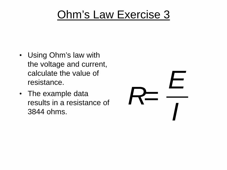
• Using Ohm’s law with the voltage and current, calculate the value of resistance.
• The example data results in a resistance of 3844 ohms.
R= EI

Ohm’s Law In Practice
• The next series of exercises will put Ohm’s Law to use to illustrate some principles of basic electronics.
• As in the previous exercise you will build the circuits and insert the VOM into the circuit in the appropriate way to make current and voltage measurements.
• Throughout the exercise record your data so that you can compare it to calculations.

Ohm’s Law In Practice
• Build up the illustrated circuit. R1 = 1 k-ohm R2 = 1 k-ohm R3 = 2.2 k-ohm R4 = 300 ohm
• Measure the current flowing through the circuit.
R1
R2 R3
R4
A+ -
Ohm’s Law In Practice
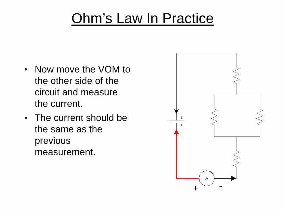
• Now move the VOM to the other side of the circuit and measure the current.
• The current should be the same as the previous measurement.
A
+ -

Ohm’s Law In Practice
• Insert the VOM at the indicated location and measure the current.
• There should be no surprise that the current is the same.
A
+
-

Ohm’s Law In Practice
• Measure the voltage across R1.
• Using Ohm’s law, calculate the voltage drop across a 1K ohm resistor at the current you measured
• Compare the result.
V
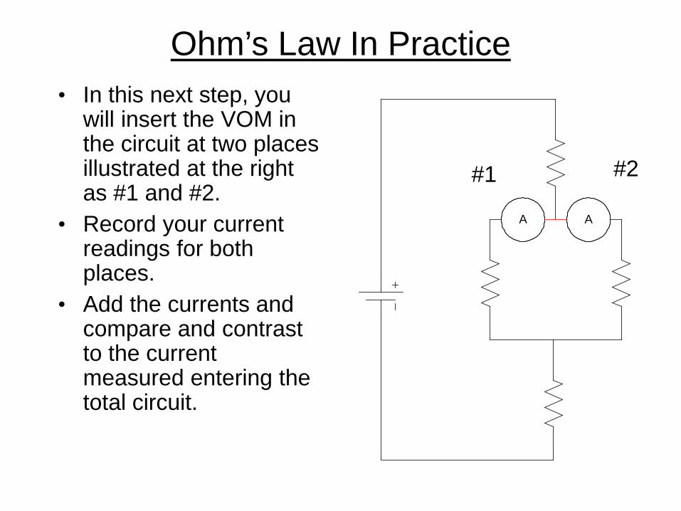
Ohm’s Law In Practice • In this next step, you
will insert the VOM in the circuit at two places illustrated at the right as #1 and #2.
• Record your current readings for both places.
• Add the currents and compare and contrast to the current measured entering the total circuit.
A A
#1 #2

Ohm’s Law In Practice
• Using the current measured through #1 and the resistance value of R2, 1k ohms, calculate the voltage drop across the resistor.
• Likewise do the same with the current measured through #2 and the resistance value of R3, 2.2k ohms.
• Compare and contrast these two voltage values

Ohm’s Law In Practice
• Measure the voltage across the parallel resistors and record your answer.
• Compare and contrast the voltage measured to the voltage drop calculated.
V
Ohm’s Law In Practice
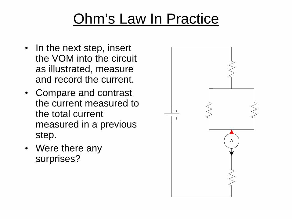
• In the next step, insert the VOM into the circuit as illustrated, measure and record the current.
• Compare and contrast the current measured to the total current measured in a previous step.
• Were there any surprises?
A

Ohm’s Law In Practice • Using the current you
just measured and the resistance of R4 (330 ohms), calculate what the voltage drop across R4 should be.
• Insert the VOM into the circuit as illustrated and measure the voltage.
• Compare and contrast the measured and calculated voltages.
V

Ohm’s Law In Practice
• There is one final measurement to complete this portion of the exercise. Insert the VOM as indicated.
• Recall the 3 voltages measured previously; across R1, R2 and R3, and across R4.
• Add these three voltages together and then compare and contrast the result with the total voltage just measured.
V

Ohm’s Law In Practice
• What you observed was: – The sum of the individual currents entering a node
was equal to the total current leaving a node . – The sum of the voltage drops was equal to the
total voltage across the circuit. • This is Kirchhoff’s law and is very useful in
the study of electronic circuits. • You also noted that Ohm’s law applied
throughout the circuit.
The Capacitor
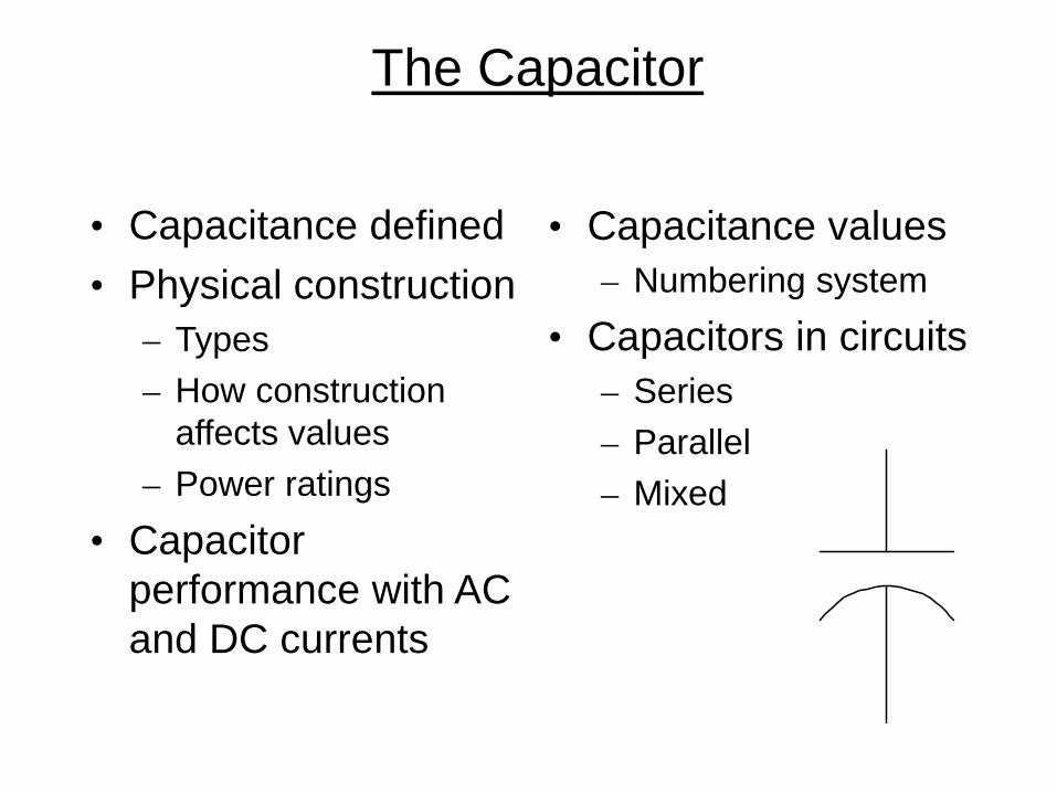
• Capacitance defined • Physical construction
– Types – How construction
affects values – Power ratings
• Capacitor performance with AC and DC currents
• Capacitance values – Numbering system
• Capacitors in circuits – Series – Parallel – Mixed

The Capacitor

The Capacitor Defined
• A device that stores energy in electric field.
• Two conductive plates separated by a non conductive material.
• Electrons accumulate on one plate forcing electrons away from the other plate leaving a net positive charge.
• Think of a capacitor as very small, temporary storage battery.
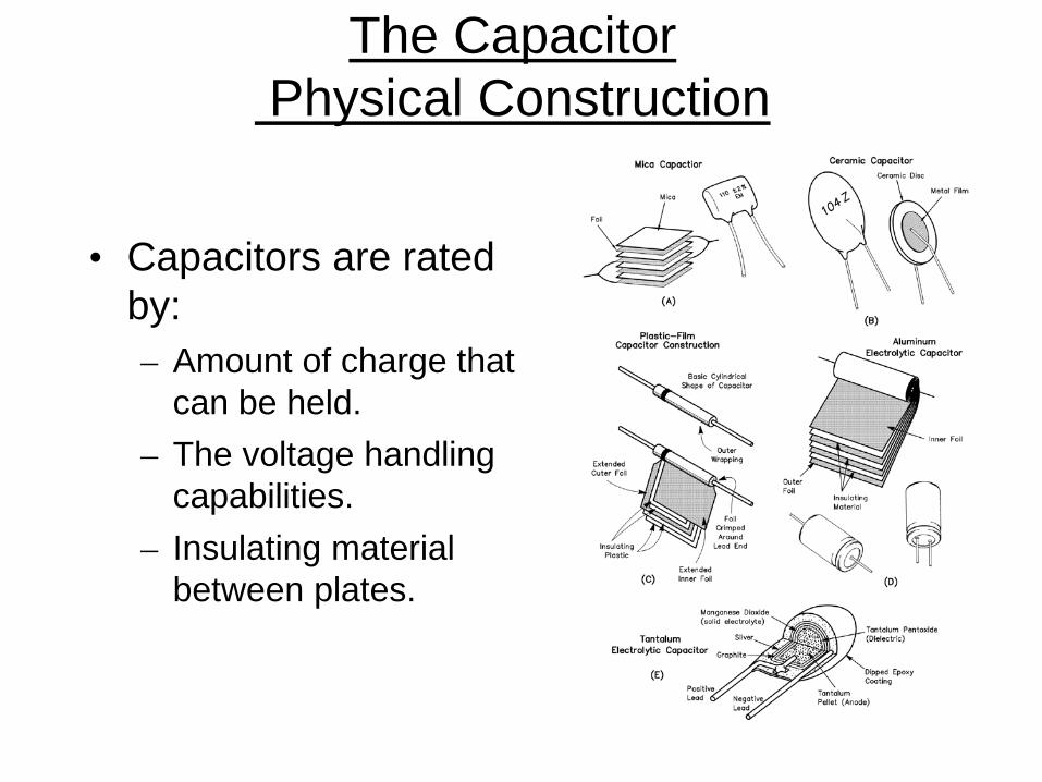
The Capacitor Physical Construction
• Capacitors are rated by: – Amount of charge that
can be held. – The voltage handling
capabilities. – Insulating material
between plates.
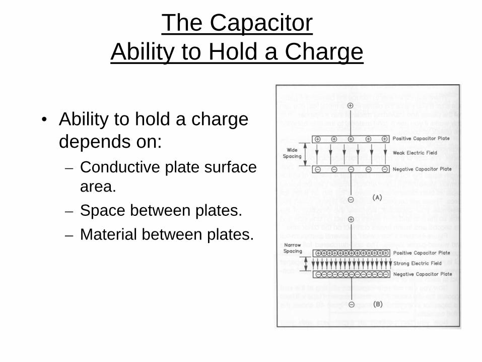
The Capacitor Ability to Hold a Charge
• Ability to hold a charge depends on: – Conductive plate surface
area. – Space between plates. – Material between plates.

Charging a Capacitor

Charging a Capacitor
• In the following activity you will charge a capacitor by connecting a power source (9 volt battery) to a capacitor.
• You will be using an electrolytic capacitor, a capacitor that uses polarity sensitive insulating material between the conductive plates to increase charge capability in a small physical package.
• Notice the component has polarity identification + or -.
+
Charging a Capacitor
• Touch the two leads of the capacitor together. • This short circuits the capacitor to make sure there is
no residual charge left in the capacitor. • Using your VOM, measure the voltage across the
leads of the capacitor

Charging a Capacitor
• Wire up the illustrated circuit and charge the capacitor.
• Power will only have to be applied for a moment to fully charge the capacitor.
• Quickly remove the capacitor from the circuit and touch the VOM probes to the capacitor leads to measure the voltage.
• Carefully observe the voltage reading over time until the voltage is at a very low level (down to zero volts).
+

Discharging a Capacitor

The Capacitor Behavior in DC
• When connected to a DC source, the capacitor charges and holds the charge as long as the DC voltage is applied.
• The capacitor essentially blocks DC current from passing through.
The Capacitor Behavior in AC
• When AC voltage is applied, during one half of the cycle the capacitor accepts a charge in one direction.
• During the next half of the cycle, the capacitor is discharged then recharged in the reverse direction.
• During the next half cycle the pattern reverses. • It acts as if AC current passes through a capacitor

The Capacitor Behavior
• A capacitor blocks the passage of DC current • A capacitor passes AC current

The Capacitor Capacitance Value
• The unit of capacitance is the farad. – A single farad is a huge amount of capacitance. – Most electronic devices use capacitors that are a
very tiny fraction of a farad. • Common capacitance ranges are: Micro 10-6
Nano 10-9
Pico 10-12
μ
p
n

The Capacitor Capacitance Value
• Capacitor identification depends on the capacitor type.
• Could be color bands, dots, or numbers.
• Wise to keep capacitors organized and identified to prevent a lot of work trying to re-identify the values.

Capacitors in Circuits
• Three physical factors affect capacitance values. – Plate spacing – Plate surface area – Dielectric material
• In series, plates are far apart making capacitance less
+
-
Charged plates far apart
CE=C1C2
C1+C2

Capacitors in Circuits
• In parallel, the surface area of the plates add up to be greater.
• This makes the total capacitance higher.
+
-
CE =C1+C2

The Inductor
• Inductance defined • Physical
construction – How construction
affects values • Inductor
performance with AC and DC currents

The Inductor
• There are two fundamental principles of electromagnetics:
1. Moving electrons create a magnetic field. 2. Moving or changing magnetic fields cause
electrons to move.
• An inductor is a coil of wire through which electrons move, and energy is stored in the resulting magnetic field.

The Inductor
• Like capacitors, inductors temporarily store energy.
• Unlike capacitors: – Inductors store energy
in a magnetic field, not an electric field.
– When the source of electrons is removed, the magnetic field collapses immediately.
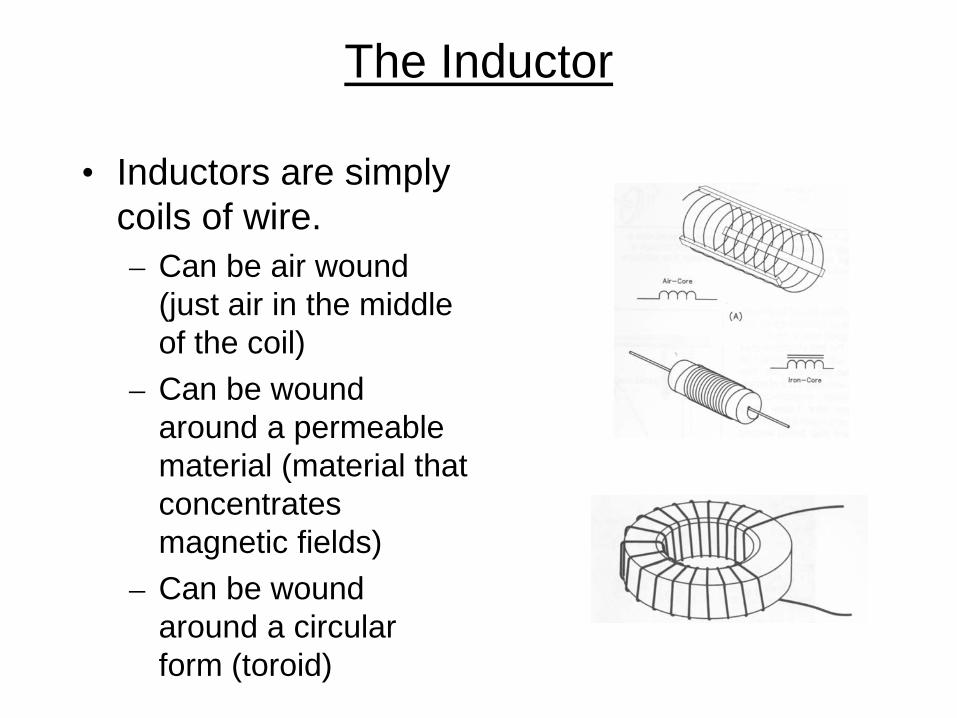
The Inductor
• Inductors are simply coils of wire. – Can be air wound
(just air in the middle of the coil)
– Can be wound around a permeable material (material that concentrates magnetic fields)
– Can be wound around a circular form (toroid)

The Inductor
• Inductance is measured in Henry(s). • A Henry is a measure of the intensity of the magnetic
field that is produced. • Typical inductor values used in electronics are in the
range of millihenry (1/1000 Henry) and microhenry (1/1,000,000 Henry)
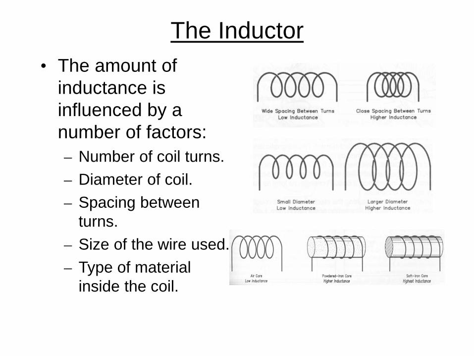
The Inductor • The amount of
inductance is influenced by a number of factors: – Number of coil turns. – Diameter of coil. – Spacing between
turns. – Size of the wire used. – Type of material
inside the coil.

Inductor Performance With DC Currents
• When a DC current is applied to an inductor, the increasing magnetic field opposes the current flow and the current flow is at a minimum.
• Finally, the magnetic field is at its maximum and the current flows to maintain the field.
• As soon as the current source is removed, the magnetic field begins to collapse and creates a rush of current in the other direction, sometimes at very high voltage.

Inductor Performance With AC Currents
• When AC current is applied to an inductor, during the first half of the cycle, the magnetic field builds as if it were a DC current.
• During the next half of the cycle, the current is reversed and the magnetic field first has to decrease the reverse polarity in step with the changing current.
• These forces can work against each other resulting in a lower current flow.

The Inductor
• Because the magnetic field surrounding an inductor can cut across another inductor in close proximity, the changing magnetic field in one can cause current to flow in the other … the basis of transformers
The Diode
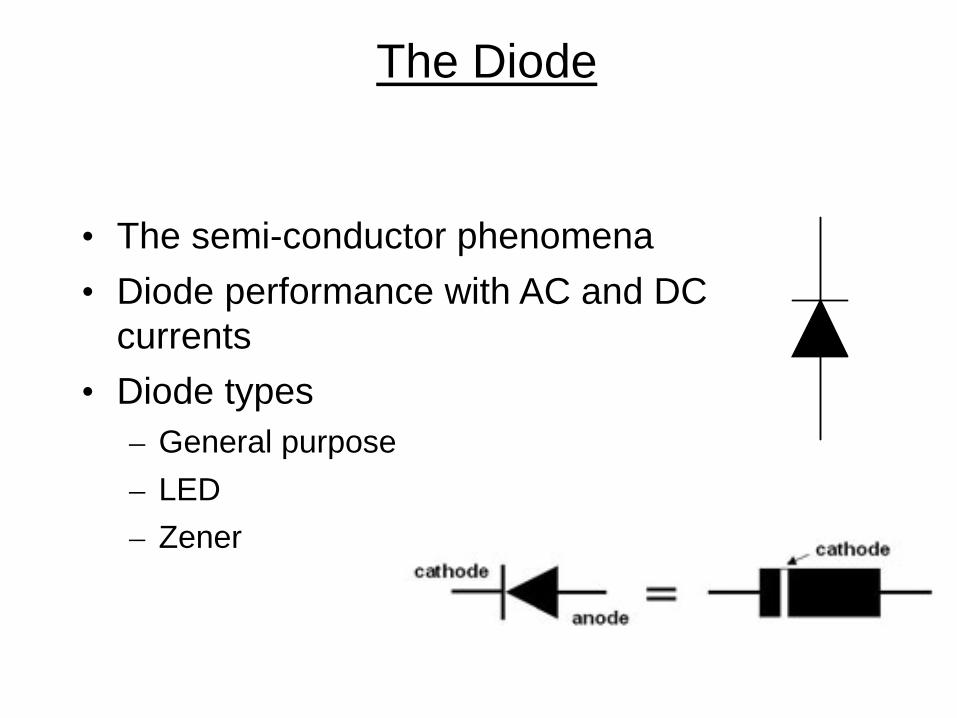
• The semi-conductor phenomena • Diode performance with AC and DC
currents • Diode types
– General purpose – LED – Zener

The Diode The semi-conductor phenomena
• Atoms in a metal allow a “sea” of electrons that are relatively free to move about.
• Semiconducting materials like Silicon and Germanium have fewer free electrons.
• Impurities added to semiconductor material can either add free electrons or create an absence of free electrons (holes).

The Diode The semi-conductor phenomena
• Consider the bar of silicon at the right. – One side of the bar is doped with negative
material (excess electrons). The cathode. – The other side is doped with positive material
(excess holes). The anode – In between is a no man’s land called the P-N
Junction.

The Diode The semi-conductor phenomena
• Consider now applying a negative voltage to the anode and positive voltage to the cathode.
• The electrons are attracted away from the junction. • This diode is reverse biased meaning no current will
flow.

The Diode The semi-conductor phenomena
• Consider now applying a positive voltage to the anode and a negative voltage to the cathode.
• The electrons are forced to the junction. • This diode is forward biased meaning current will
flow.

The Diode
• Set up the illustrated circuit on the proto board.
• Note the cathode (banded end) of the diode.
• The 330 ohm resistor in the circuit is a current limiting resistor (to avoid excessive diode current).
A
330

The Diode
• Use the same circuit, but reverse the diode.
• Measure and record the current.
A

The Diode
• Build the illustrated circuit.
• Measure the voltage drop across the forward biased diode.
V

The Diode with AC Current
• If AC is applied to a diode: – During one half of the cycle the diode is forward
biased and current flows. – During the other half of the cycle, the diode is
reversed biased and current stops. • This is the process of rectification, allowing
current to flow in only one direction. • This is used to convert AC into pulsating DC.

The Diode with AC Current
Input AC Voltage
Output Pulsed DC Voltage
Diode conducts
Diode off

The Light Emitting Diode
• In normal diodes, when electrons combine with holes current flows and heat is produced.
• With some materials, when electrons combine with holes, photons of light are emitted, this forms an LED.
• LEDs are generally used as indicators though they have the same properties as a regular diode.

The Light Emitting Diode
• Build the illustrated circuit on the proto board.
• The longer LED lead is the anode (positive end).
• Observe the diode response
• Reverse the LED and observe what happens.
• The current limiting resistor not only limits the current but also controls LED brightness.
330

Zener Diode • A Zener diode is
designed through appropriate doping so that it conducts at a predetermined reverse voltage. – The diode begins to
conduct and then maintains that predetermined voltage
• The over-voltage and associated current must be dissipated by the diode as heat
9V 4.7V

The Transistor (Electronic Valves)
• How they work, an inside look • Basic types
– NPN – PNP
• The basic transistor circuits – Switch – Amplifier

The Transistor
emitter
base
collector

The Transistor
N P Ncollector emitter
base
e - e -forward bias
conducting e -
The base-emitter current controls the collector-base current

The Transistor
N P Ncollector emitter
base
e - e -reverse bias
non-conducting

The Transistor • There are two basic types of
transistors depending of the arrangement of the material. – PNP – NPN
• An easy phrase to help remember the appropriate symbol is to look at the arrow. – PNP – pointing in proudly. – NPN – not pointing in.
• The only operational difference is the source polarity.
PNP
NPN

The Transistor Switch
• During the next two activities you will build a transistor switch and a transistor amplifier.
• The pin out of the 2N3904 transistor is indicated here.
C B E

The Transistor Switch
• Build the circuit on the proto board.
• Use hook up wire to serve as “switches” to connect the current to the transistor base.
• What happens when you first apply power when the base is left floating (not connected)?
330
1000
9-volt
The Transistor Switch
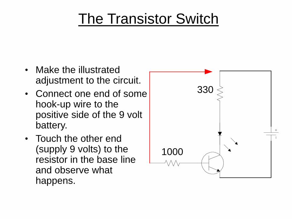
• Make the illustrated adjustment to the circuit.
• Connect one end of some hook-up wire to the positive side of the 9 volt battery.
• Touch the other end (supply 9 volts) to the resistor in the base line and observe what happens.
330
1000
The Transistor Switch
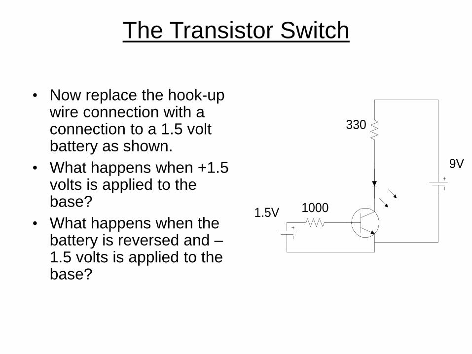
• Now replace the hook-up wire connection with a connection to a 1.5 volt battery as shown.
• What happens when +1.5 volts is applied to the base?
• What happens when the battery is reversed and –1.5 volts is applied to the base?
330
10001.5V
9V
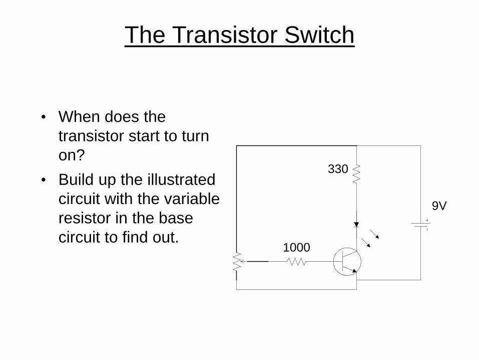
The Transistor Switch
• When does the transistor start to turn on?
• Build up the illustrated circuit with the variable resistor in the base circuit to find out.
330
1000
9V

Putting It All Together
• Simple construction project

Conclusion
• Not really - your journey to understand basic electronics has just begun!
• This course was intended to introduce you to some concepts and help you become knowledgeable in others.