basic concept and benefits - metroplex alternator ... · pdf filebasic concept and benefits...
TRANSCRIPT

The following article is provided through the courtesy of ‘GM TechLink, GM Service and Parts Operations service publication for Technicians’
Basic concept and Benefits
Traditional charging systems use an internal temperature sensor inside the generator to establish generator voltage set points. When the generator is cold, it raises the voltage output set point. When the generator is hot, it lowers the voltage output set point. This type of system tends to overcharge the battery on long trips at highway speeds and undercharge the battery on short trips with low vehicle speeds.
Regulated Voltage Control (RVC) is a new dynamic control of the vehicle’s system voltage. It regulates the generator’s output voltage, based mainly on estimated battery temperature and battery state-of-charge. The main benefits of this system are:• Improved fuel Economy• Extended battery life• Extended lamp life• Extended switch life
There are two types of RVC systems used todayIntegrated RVC andStand-alone RVC (SARVC).
Integrated systems use a battery current sensor to provide a body controller (BCM) the amount the battery is charging or discharging. Accurate voltage measurements are taken through the battery positive voltage and ignition 1-voltage circuits. The BCM then communicates information over serial data circuits for the ECM/PCM to directly control the generator.
SARVC systems do not use the BCM for operation. They have a generator battery control module mounted to the negative battery cable, to interpret battery current and voltage, and battery temperature inputs. The battery current sensor is internal to the module. This module also directly controls the generator L-terminal duty cycle instead of the ECM/PCM.
Both types of system have two types of corrective actions to insure the battery stays at 80% state of charge. These include up to three levels of load shed and up to three levels of idle boost operation. Refer to the (GM) service manual Description and Operation for load shed and idle boost.
We will discuss the basic operation of the RVC system, the three different generations of systems used today on GM vehicles, components used on each separate system and general diagnostic information section.
system operationNot all systems will enter all modes of operation; refer to the applicable (GM) service manual for exact Description and Operation.
The purpose of the RVC system is to maintain the battery state-of-charge at 80% or above and support vehicle loads.
The six modes of operation include:Charge ModeFuel Economy ModeVoltage Reduction ModeStart Up ModeWindshield Deice ModeBattery Sulfation Mode
The PCM/ECM (generator battery control module on full-size trucks) controls the generator through the generator L-terminal control circuit. It monitors the generator performance through the generator field duty cycle signal circuit. The signal is a 5 volt PWM (pulse width modulated) signal of 128Hz with a duty cycle of 0-100%. Normal duty cycle is between 5-95%. The ranges between 0-5% and 95-100% are for diagnostic purposes. The following table shows the commanded duty cycle and output voltage of the generator:
duty cycle Generator Voltage set point
10% 11.0V
20% 11.56V
30% 12.12V
40% 12.68V
50% 13.25V
60% 13.81V
70% 14.37V
80% 14.94V
90% 15.5V
page onewww.waiglobal.com • 1-800-877-3340
The generator provides a feedback signal of the generator load through the generator field duty cycle signal circuit to the control module. The signal is a 5 volt PWM signal of 128 Hz, with a duty cycle if 0-100%. Normal cycle is between 5-99%. The ranges between 0-5% and 100% are for diagnostic purposes.
charGe modeThe control module enters Charge Mode whenever one of the following conditions is met:
Under WOT conditions and when the fuel rate (sent by the • ECM/PCM) is greater than 21 g/s and the throttle position is greater than 90%.The headlamps are ON, low or high beam.• The wipers are ON for more than 8 seconds.• The electric cooling fans are ON high speed.• The rear defogger is ON.• The Battery SOC (state of charge) is less than 80%.•
When one of these conditions is met, the control module ramps up the voltage slowly to a level between 13.4 and 15.5 volts (depending upon the mode of operation the system is presently in) at a rate of 8 mV to 50 mV per second.
fuel economy mode The control module enters Fuel Economy Mode when the following conditions are met:
The calculated ambient air temperature is above 0°C (32°F).• The calculated battery current is less than 15 amperes and greater • than -8 amperes.The battery state of charge is greater than 80%.• The generator field duty cycle is less than 99%.•
Its targeted generator output voltage is 13.0 volts. The control module will exit this mode once the criteria are met for Charge Mode.
VoltaGe reduction modeThe control module will enter Voltage Reduction Mode when the following conditions are met:
The calculated ambient air temperature is above 0°C (32°F).• The calculated battery current is less than 2 amperes and greater • than -7 amperes.The generator field duty cycle is less than 99%.•
Its targeted generator output voltage is 12.9 volts. The control module will exit this mode once the criteria are met for Charge Mode.
start up mode After the engine has started, the control module sets a targeted generator output voltage of 14.5 volts for 30 seconds.
Battery sulfation mode The control module enters this mode when the battery voltage is less than 13.2 volts for 45 minutes. Once in this mode, the generator battery control module will set a targeted output voltage between 13.9 to 15.5 volts for 5 minutes. The control module will then determine which mode to enter depending on voltage requirements.
rVc modeThe control module bases the charging voltage on battery state of charge (SOC). Battery SOC is estimated during a key off event every 8 hours, after 3 voltage measurements every 24 hours thereafter, and then monitored constantly while the ignition is on. These measurements of voltage are then compared to estimated battery temperature, as battery temperature vs. battery voltage directly corresponds to battery SOC. While the engine is running, the system uses both the battery voltage and estimated battery temperature to determine the battery current in and out of the battery. The control module then regulates the charging voltage to keep the battery above an 80% SOC.
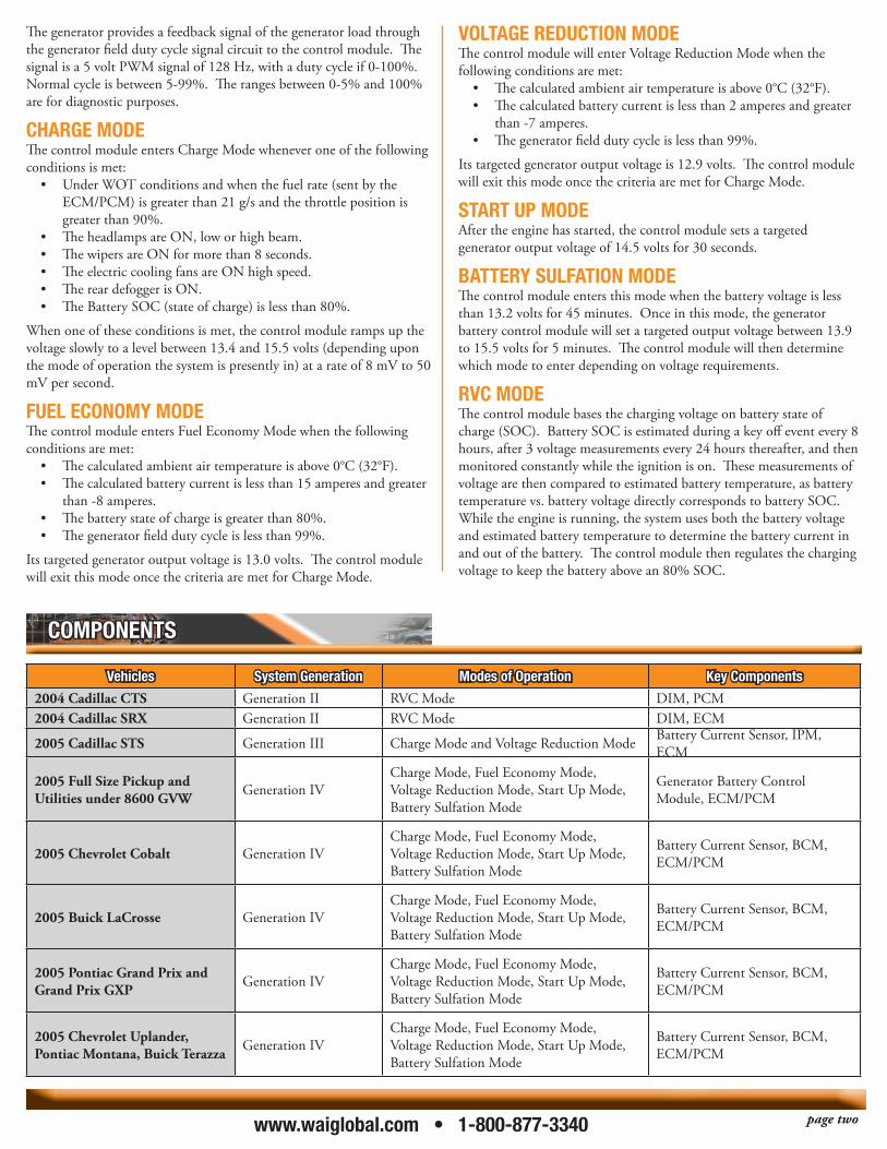
Vehicles system Generation modes of operation Key components
2004 Cadillac CTS Generation II RVC Mode DIM, PCM2004 Cadillac SRX Generation II RVC Mode DIM, ECM
2005 Cadillac STS Generation III Charge Mode and Voltage Reduction Mode Battery Current Sensor, IPM, ECM
2005 Full Size Pickup and Utilities under 8600 GVW Generation IV
Charge Mode, Fuel Economy Mode, Voltage Reduction Mode, Start Up Mode, Battery Sulfation Mode
Generator Battery Control Module, ECM/PCM
2005 Chevrolet Cobalt Generation IVCharge Mode, Fuel Economy Mode, Voltage Reduction Mode, Start Up Mode, Battery Sulfation Mode
Battery Current Sensor, BCM, ECM/PCM
2005 Buick LaCrosse Generation IVCharge Mode, Fuel Economy Mode, Voltage Reduction Mode, Start Up Mode, Battery Sulfation Mode
Battery Current Sensor, BCM, ECM/PCM
2005 Pontiac Grand Prix and Grand Prix GXP Generation IV
Charge Mode, Fuel Economy Mode, Voltage Reduction Mode, Start Up Mode, Battery Sulfation Mode
Battery Current Sensor, BCM, ECM/PCM
2005 Chevrolet Uplander, Pontiac Montana, Buick Terazza Generation IV
Charge Mode, Fuel Economy Mode, Voltage Reduction Mode, Start Up Mode, Battery Sulfation Mode
Battery Current Sensor, BCM, ECM/PCM
components
page twowww.waiglobal.com • 1-800-877-3340
Battery current sensor The battery current sensor is a serviceable component that is connected to the negative battery cable at the battery. The battery current sensor is a 3-wire Hall-effect current sensor. The battery current sensor monitors the battery current. It directly inputs to the BCM. It creates a 5 volt PWM signal of 128 Hz with a duty cycle of 0-100%. Normal duty cycle is between 5-95%. The ranges between 0-5% and 95-100% are for diagnostic purposes.
Body control module (Bcm), instrument panel module (ipm) and dash inteGration module (dim)The BCM determines the output of the generator and sends the information to the ECM/PCM for control of the generator L-terminal control circuit. It monitors the generator field duty cycle signal circuit information sent from the ECM/PCM that determines the generator electrical load. It monitors the battery current sensor, the battery positive voltage circuit, and estimated battery temperature to determine battery state of charge (SOC). The BCM performs, or sends, commands to ECM or other controllers to perform idle boost and load management operations.
ecm/pcm The ECM/PCM directly controls the generator field control circuit input to the generator. The ECM/PCM receives control decisions based on messages from the BCM/IPM. It monitors the generator field duty cycle signal circuit and sends the information to the BCM/IPM. On some vehicles, the ECM/PCM overrides the control decision of the BCM/IPM when the following conditions are met:
The engine cooling fans are ON high speed.• There is a high fuel demand.• The calculated ambient air temperature is less than 0°C (32°F).•
instrument panel cluster (ipc) The IPC provides a means of driver notification in case of a charging system failure. Refer to the (GM) service manual for exact operation.
Generator Battery control module It communicates with the PCM, IPC and BCM for RVC operation. It is a serviceable component that is connected to the negative battery cable at the battery. It directly controls the generator field control circuit input to the generator. It monitors the generator field duty cycle signal circuit, its internal battery current sensor, the battery positive voltage circuit, and estimated battery temperature to determine battery state of charge (SOC).
Diagnostics are specific for each vehicle that uses this system. Refer to the applicable (GM) service manual for DTC information.
For L-terminal diagnostics, set your DVOM to monitor frequency. When the system is operating normally, you should read a duty cycle of 5-95% depending upon which mode the system is in and also the battery SOC. The 5-volt reference signal for the PWM signal is provided by the generator and cycled to ground by the ECM/PCM or generator battery control module, depending on the system.
For F-terminal diagnostics, set your DVOM to monitor frequency. When system is operating normally, you should read a duty cycle of 5-99% depending on which mode the system is in and also the battery SOC. The ECM/PCM or generator battery control module, depending on the system, provides the 5-volt reference signal for the PWM signal and is cycled to ground by the generator.
The (GM scan tool) Tech 2 may include some of the following parameters:
ECM/PCM BCM/DIM/IPMGenerator L-Terminal Battery current SensorGenerator F-Terminal Battery VoltageBattery Voltage Ignition Voltage
Load Shed LevelIdle Boost Level
The generator battery control module incorporates most of the scan tool parameters, except load shed and idle boost, as this system does not take corrective actions.
If you feel there is a charging system error, first check for related charging system and low voltage DTCs set in the control module.
TIP: Diagnose P codes first, as these DTC will set if there is a generator or control circuit failure.
In no DTCs are present, refer to the Charging System test in the (GM) service manual. If this test does not present a failure, you many need to test drive the vehicle and monitor the idle boost and load shed parameters. This may lead you to some type of high load condition that may be normal; compare to a known-good vehicle.
Transpo note: While this GM RVC tech article dates to September 2004, we hope you found it enlightening and educational. Again, our thanks to GM TechLink, GM Service and Parts Operations service publication for Technicians.To obtain service parts for GM RVC alternators please contact your authorized Transpo – WAI product distributor.
diaGnostics
page threewww.waiglobal.com • 1-800-877-3340