bar top 52 on ground pool system - pool supplies canada€¦ · latham pool products page 1...
TRANSCRIPT

Bar Top 52" On Ground
Pool SystemGENERAL INSTALLATION GUIDE
Latham Pool Products page 1 52" Bar Top Installation Manual
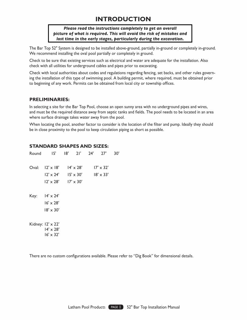
INTRODUCTION
The Bar Top 52" System is designed to be installed above-ground, partially in-ground or completely in-ground. We recommend installing the oval pool partially or completely in ground.
Check to be sure that existing services such as electrical and water are adequate for the installation. Also check with all utilities for underground cables and pipes prior to excavating.
Check with local authorities about codes and regulations regarding fencing, set backs, and other rules govern-ing the installation of this type of swimming pool. A building permit, where required, must be obtained prior to beginning of any work. Permits can be obtained from local city or township offices.
PRELIMINARIES:In selecting a site for the Bar Top Pool, choose an open sunny area with no underground pipes and wires, and must be the required distance away from septic tanks and fields. The pool needs to be located in an area where surface drainage takes water away from the pool.
When locating the pool, another factor to consider is the location of the filter and pump. Ideally they should be in close proximity to the pool to keep circulation piping as short as possible.
STANDARD SHAPES AND SIZES:Round 15' 18' 21' 24' 27' 30'
Oval: 12' x 18' 14' x 28' 17' x 32'
12' x 24' 15' x 30' 18' x 33'
12' x 28' 17' x 30'
Key: 14' x 24'
16' x 28'
18' x 30'
Kidney: 12' x 22' 14' x 28' 16' x 32'
There are no custom configurations available. Please refer to “Dig Book” for dimensional details.
Please read the instructions completely to get an overall picture of what is required. This will avoid the risk of mistakes and
lost time in the early stages, particularly during the excavation.

Latham Pool Products page 2 52" Bar Top Installation Manual
TECH-TALK…Technical Information for Pool ProfessionalsDecember 4, 2014
Bartop Steel Onground Pools
All Bartop Onground pools will now require four (4) compression
straps at each panel flange. Previously only two (2) compression straps
were required on the bottom half of each panel. To insure the integrity
and longevity of the Bartop product line, we have added compression
straps to the top half of each panel. There will now be four compres-
sion straps provided with each Bartop pool kit to allow for installation
on both the top and bottom half of each panel on both sides of the
flange. It is mandatory that all of the required straps are installed along
with all bolt holes utilized. Failure to install all straps and bolts will re-
sult in voiding the warranty and may affect the safe use of the pool. We
will be placing the following warning label on each panel in the four
(4) locations where the compression straps are required.

Latham Pool Products page 3 52" Bar Top Installation Manual
MATERIALS REQUIRED• Compaction Sand (Brick Sand)
• Stone Dust
• Concrete for Collar
BOTTOM MIXTwo types of bottom mix can be installed.
• Sand Bottom – using compacted brick sand (sand free of stones or large particles).
• Hard Bottom – using an available bottom mix from ready mix or building supply companies or mixing on site from Portland cement and brick sand.
POOL LAYOUTStake out an area two foot wider than the actual pool size. Mark this area with chalk or spray paint. Refer to “Dig Book” for dimensional details.
17' ROUND

Latham Pool Products page 4 52" Bar Top Installation Manual
PREPARING THE SITETrace the perimeter of the pool and cover the collar with stone dust 3" thick and 12" wide. Compact and level the stone dust, place a concrete slab (Patio stone) at each panel joint. (Panel joint centered over the top of the patio stone). Check level of each stone slab. The pool will rest on these leveling blocks.
Sequence for base on round pools.
PANEL INSTALLATION – ROUNDThe panels are bolted together in sequence, ensuring that the panel joints are centered over the cement slabs. All bolt holes must be used. Leaving bolts out will void the warranty. If ground preparations have been carefully done, little adjustments will be required. Four compression straps are provided for each panel joint. The strap is located above and below the middle horizontal bar on each side of the panel joint (see diagram below).The compression straps must be used at all panel joints on round pools. Not using the compression straps at all panel joints will void the warranty. Once the panels are bolted together, check to ensure pool is (A) level; and (B) complies to the exact dimensions appropriate for that model. Note: Not using the compression straps at all panel joints will void the warranty and could cause product failure.
CONNECTION ORDER
1. Panel Joint
2. Compression Strap (4 per flange)
3. Brace (when applicable)
1
32
2
Add compression straps to the top of the panel in the illustration showing total of 4 with two on each side of flange.
Latham Pool Products page 5 52" Bar Top Installation Manual
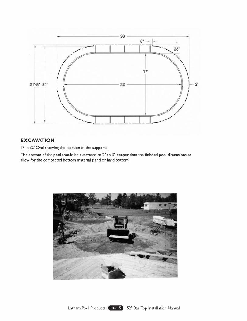
EXCAVATION17' x 32' Oval showing the location of the supports.
The bottom of the pool should be excavated to 2" to 3" deeper than the finished pool dimensions to allow for the compacted bottom material (sand or hard bottom)

Latham Pool Products page 6 52" Bar Top Installation Manual
Sequence for base on oval pools.
PANEL INSTALLATION – OVAL, KEY, AND KIDNEY POOLSThe additional steps for ovals, not required for rounds, is the squaring of the two parallel straight walls and the assembly of the metal components forming the A-Frame wall supports. These wall supports must be attached at locations shown on the specification drawing supplied by the manufacturer. Make sure all bolts are in place and tightened up.
Four compression straps are provided for each panel joint. The strap is located above and below the middle horizontal bar on each side of the panel joint (see page 5). The compression straps must be used at all panel joints on Oval, Key, and Kidney pools. NOTE: Not using the compression straps at all panel joints will void the warranty and could cause product failure.
The blocks are shown sitting up on the stone dust for illustrative purposes. Once the blocks are set and leveled you should fill in between the blocks with additional stone dust so there will be no voids under the pool walls once erected.
TYPICAL OVAL STRUCTURAL INSTALLATION ELEMENTS:
Sand or Hard Bottom
Wall Brace
Cement Bond Beam
Stone Dust Base
All ovals require to be installed a minimum of 14" below grade. A cement pad 24" wide and 10" deep must encase the oval braces and extend past both end braces by a minimum of 4".
REMAINING FILL
SLAB
REMAINING FILL
SAND
COMPACTEDSTONE

Latham Pool Products page 7 52" Bar Top Installation Manual
PANEL BRACE INSTALLATIONSpecial care must be taken to install all neces-sary braces as displayed on the specifications. The structural integrity of the pool is dependent upon the braces and concrete collar. The braces are a special three piece configuration designed specifically for this pool and may not be changed or substituted.
Picture showing attachment points for the three piece brace.
The panel holes are symmetrical, once the bottom brace is attached, the next two braces align to the proper panel holes.
Note attachment points for the mid and long braces to the short brace.
1 - PANEL RIGIDIZING BARS
2 - SHORT (HORIZONTAL BRACE)
4 - DRIVE STAKE
The horizontal brace is attached to the first hole above the panel rigidizing bar.
The mid and long braces are attached to 3rd hole from the end of the horizontal brace.
The drive stake is bolted to the brace through the aligning holes. The drive stake will stabilize the brace and panel and eliminate sliding. It is an important part of the structure.

Latham Pool Products page 8 52" Bar Top Installation Manual
POOL STEP INSTALLATION: STEP PANELS
Special step panels are provided to facilitate the step installation. These panels have a wider side flange to enable the installer to bolt the steps to the panels. The panels are supplied and installed on the left and right side of the step. The braces also attach to the junction of the step and panel.
NOTE: The panels are symmetrical and can be used on either side by flipping them upside down.

Latham Pool Products page 9 52" Bar Top Installation Manual
The step side flanges on both sides will need to be notched out 4" at the bottom to allow the step to sit on top of the connector panel. This is easily done with a hack saw on site.
VERY IMPORTANT:
To be compliant when using the step, the bottom riser height from the finished floor to the bottom tread must not exceed 12".
POOL STEP INSTALLATION – STEP CONNECTOR
With the availability of moulded steps limited to 48", the 52" wall uses a step connector which is installed between the step panels and below the step. It is specifically designed for the recommended 6' radius step. It is bolted to the two step panels and provides structural support for the step. This connec-tor must be used for all step instal-lations.
PART # ZPN-RA072114SC

Latham Pool Products page 10 52" Bar Top Installation Manual
VERY IMPORTANT
• The supplied step tread supports must be used.
• The tread supports must be anchored by concrete.
• The Brace must be anchored by concrete. Concrete must be a minimum of 24" wide and 10" deep and extend a minimum of 4" past each step support brace.
POOL STEP INSTALLATION: STEP ATTACHMENT AND BRACES
Clamp the step to the steel panel (“C” clamps) and then drill through the holes in the steel panel to create holes in the step flange. Use four compres-sion straps, one each side of the steel panel flange and the step flange, top and bottom. Insert the standard panel bolts through each hole and tighten to secure step to the panel.
The second set of holes on the step panel outer edge are for the attach-ment of the three piece brace which must be used on each side of the step.
The holes are designed to be compat-ible with the supplied brace only and are angled for maximum support for the molded step.
One Brace is required for each side of the step.
VERY IMPORTANT:When using a moulded step, the pool must be a minimum of 14" below grade. There must be a wall support/brace and concrete on each side of the step.
Latham Pool Products page 11 52" Bar Top Installation Manual
NOT PERMIT
TED
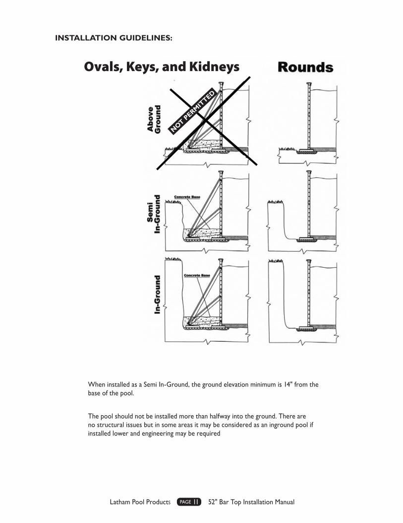
When installed as a Semi In-Ground, the ground elevation minimum is 14" from the base of the pool.
The pool should not be installed more than halfway into the ground. There are no structural issues but in some areas it may be considered as an inground pool if installed lower and engineering may be required
INSTALLATION GUIDELINES:
Ovals, Keys, and Kidneys

Latham Pool Products page 12 52" Bar Top Installation Manual
NOTE: If installing fully in ground, check with local codes for additional permit and engineering requirements. On ground pools normally do not require engineering wet stamps but that may change if pool is installed fully in the ground.
FAILURE TO OBSERVE THESE GUIDELINES WILL VOID ALL WARRANTIES
SKIMMER INSTALLATIONEach pool kit comes with one skimmer panel with the appropriate opening to accommodate a skimmer. Please refer to manufacturer’s installation instruction included in each skimmer package.
RETURN FITTING INSTALLATIONEach pool kit comes with one or two return panel with the appropriate opening to accommodate return fittings. Please refer to manufacturers installation instruction included in each skimmer/return package.
MAIN DRAIN INSTALLATIONYou have the option of installing a main drain with your pool. It is not a standard feature on every pool. If you are exercising this option it must be installed and conform to the ANSI/APSP/ICC-5 2011 Standard which requires two main drains connected in tandem with a minimum distance between each of 3'. If using a sand bottom a cement pad approximately 24" x 48" x 3" should be poured in the proper location in the pool bottom to hold the main drains in place. If you are using a grout/hard bottom, the grout around the main drains in an area of approximately 24" x 48" should be made thicker than the rest of the bottom. Recommend a minimum thickness of three to four inches.
CEMENTING THE WALLS: OVAL, KEY, AND KIDNEY WALLS AND STEPSIf you are installing an Oval, Key, or Kidney pool, the walls and braces have to be anchored with cement in the way shown in the diagram below and on the dig print. It must be installed a minimum of 14" into the ground.
CEMENT PAD24" wide and 10" deep
Extend past both end braces by a minimum of four inches.
Rounds without steps do not require any concrete.
COMPRESSION STRAP INSTALLATIONFour compression straps are provided for each panel joint. The strap is located above and below the horizontal bar on each side of the panel joint. The compression straps must be used at all panel joints. NOTE: Not using the compression straps will void the warranty and could cause product failure.

Latham Pool Products page 13 52" Bar Top Installation Manual
CIRCULATION AND FILTER INSTALLATIONAfter the skimmer and returns are installed, the connecting piping and filter can be connected. A flexible PVC piping is recommended with a 75 PSI Rating. There are slip fit and clamp or glued spa pipe options. We will discuss the slip fit and clamp type.
Install all the needed fittings in the back of the return, bottom of skimmer and pump, and filter. Make sure thread sealant is used on each fitting.
The filter should be set up on a cement pad or stable base. Remember once the filter is filled with sand it will be heavy and should be positioned prior to filling.
Lay out the plastic piping allowing it to warm and become flexible. Cut and slide over the barbed fittings. This is a tight fit and heating the pipe end with hot water will make it more pliable and easier to slide on the barbed fitting. Slip the clamps on the pipe prior to connecting to the barbed (treaded adapter) fitting.
Repeat this process until all the pipes are connected.
If the pool has two returns, a “T” connector can be used to bring the two fittings into a single line. The Skim-mer is connected to the Pump front and the returns are connected to the filter out port.
Connect the filter and pump together following the instructions provided in the package by the manufacturer.
TIPS • All piping should be kept at a minimum length to increase circulation efficiency.
• The fittings are made for 1-1/2" piping, do not reduce diameters as it will effect system efficiency.
• Avoid placing the filter and pump too far above the pool water level.
• If unavoidable, use an inline check valve on the suction side.
• If installing below the water level, use shut off valves on both return and suction side to enable you to control the water when servicing the filter or pump.
• Keep piping away from sharp edges, braces, rocks, or concrete – any of which can puncture or kink the piping.
• When using thread sealant, use only sealant formulated for plastic piping, Teflon tape, or Silicone.
• All plumbing lines should be pressure tested prior to filling the pool and starting up the system.
BACKFILLING THE POOLIf the pool is installed partially or fully in the ground, it is recommended that the working area/over dig is back-filled and graded to allow water to drain away from the pool. This will protect your pool from excessive frost action or settling that can be aggravated by standing water around the structure. It is also recommended that a drainage pipe is installed around the pool leading the end out to a low area to allow for water to drain out from around the structure.
The pool can be backfilled before or after the liner and water is added but we recommend that, with pools fully in the ground, it is done after the water is in the pool.
Latham Pool Products page 14 52" Bar Top Installation Manual
POOL BOTTOM PREPARATIONIf the pool bottom is dry and free of groundwater the sand base or hard bottom mix can be applied directly to the firm earth. Both methods require two to three inches of mix. If you have water from a high water table, this must be controlled before you can finish the bottom, and it is also recommended that only a hard bottom is used.
To control the water, the pool should be excavated to a depth 6" more than normal, the 6" is filled with clear stone to allow the water to flow through into a sump or collection area in the lowest part of the pool. A simple foot-valve installed at this point and connected to a pump outside of the pool can dewater the shell while work continues. Once the bottom is finished and the liner and water installed, the pipe/pump can be disconnected and continued use will not be required.
SAND POOL BOTTOMWith a sand bottom, rake the sand around to provide uniform coverage to the bottom, then it can be wetted with a fine spray of water to dampen but not saturate the sand. This will make the sand workable and can be made smooth by first dragging a straight edge (2x4) over the sand, then using a cement trowel, smoothing out all the irregularities. Remember any irregularities in the bottom will be visible once the liner is installed.
HARD POOL BOTTOM
As with sand, the mix can be applied directly to the firm pool bottom, or as with the water problem, to the gravel base. The mix is available pre-bagged from a local supplier or can be mixed on site from Portland cement and brick sand. The usual mix is at a 3:1 or 4:1 ratio of sand and cement. The mix has to be damp but not satu-rated to be workable. The test is to grab a handful of the wetted mix, squeeze together and it should retain its shape. If it squeezes out and slums, it is too wet. If it falls apart, it is too dry.
As with sand, spread the mix over the pool bottom and trowel smooth. This needs to be done as a continuous process to avoid seaming. Start at one end and work to the other end of the pool. This is one process where it is recommended that a professional is retained.
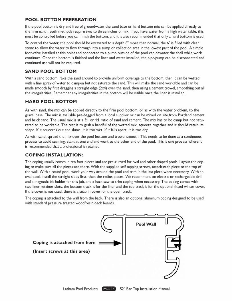
COPING INSTALLATION:The coping usually comes in ten foot pieces and are pre-curved for oval and other shaped pools. Layout the cop-ing to make sure all the pieces are there. With the supplied self tapping screws, attach each piece to the top of the wall. With a round pool, work your way around the pool and trim in the last piece when necessary. With an oval pool, install the straight sides first, then the radius pieces. We recommend an electric or rechargeable drill and a magnetic bit holder for this job, and a hack saw to trim coping when necessary. The coping comes with two liner retainer slots, the bottom track is for the liner and the top track is for the optional fitted winter cover. If the cover is not used, there is a snap in cover for the open track.
The coping is attached to the wall from the back. There is also an optional aluminum coping designed to be used with standard pressure treated wood/resin deck boards.
Coping is attached from here
(Insert screws at this area)
Pool Wall

Latham Pool Products page 15 52" Bar Top Installation Manual
INSTALLING THE LINERVinyl liners are best installed in warm weather. The liner is easier to handle and the packing wrinkles will disappear more readily. If the liner is to be installed in cool weather, store the liner indoors in a warm area for several days prior to installation.
STEP 1:Double check the pool bottom surface to make sure there are no sharp stones or objects that may damage the liner. Inspect the walls to ensure cement splatters or other objects are removed. The steel wall should be dry and clean.
STEP 2:Install the gaskets on the skimmer and the return fittings as per manufacturer’s instructions. Install the (optional) main drain gaskets.
STEP 3:Tape all the wall panel joints with duct tape. Also tape the bottom of the coping where it meets the pool wall. This will provide a good seal to enable the vacuum to remove all the air and shape the liner better. NOTE: Do not use any colored tape or tape with adhesives that may leach out and effect the liner.
STEP 4:NOTE: With a hard bottom, this can be done in the pool, with a sand bottom it has to be done outside of the pool. Take the liner out of the box and unfold. Make sure there are no sharp objects on the ground and the area is free of loose objects. Pull the liner over the wall. Make sure you do not catch the liner on any sharp edges. Prior to this step, it is advisable to inspect the area and tape any potential sources of cutting or damaging the liner.
STEP 5:Take two corners or sides with a round pool and walk the liner to drape over the pool bottom. This can be done with two people, but is much easier with four people. Hold onto the liner wall and position the liner to conform to the pool shape. Avoid dragging the liner along the pool bottom to minimize disturbing the smooth sand bottom.
STEP 6:Insert the liner bead into the lower track, working around the pool until all the bead is in the track. Any adjust-ments required to square the liner to the pool must be made now (only with ovals and shaped pools). Make sure the bead is firmly in the track.
STEP 7:You will be using an industrial or shop vacuum to remove the air from between the liner and pool wall.
Take the hose from the vacuum and insert through the skimmer top and front so the hose end is approximately 18" from the pool wall top, between the liner and wall.
STEP 8:Using tape, seal around the vacuum hose and skimmer top, and also seal the openings in the circulation pipes if the filter is not installed.
STEP 9:Start the vacuum cleaner. The liner will start to draw against the pool wall as the air is being removed. The liner should conform to the pool shape and be smooth all over. If there are wrinkles or folds which will not come out, the liner may have to be shifted by pulling the bead out of the track and rotating the liner. This has to be repeated until the liner fits the pool with no wrinkles.

Latham Pool Products page 16 52" Bar Top Installation Manual
NOTE: Do not add water or cut any fittings until you are satisfied with the fit. Water will not remove wrinkles or folds in the liner and once you have added water or cut any openings, the liner is not returnable.
Be careful with tools and walk only with stocking feet on the liner.
STEP 10:Once the liner is in place and you are satisfied with the fit, start filling the pool with water. If you will be filling from a water truck, use a hose first to add three to five inches of water, this will act as a shield for the sand bottom. The water coming out of the trucks large diameter hose can make a depression in the pool bottom.
When the pool has six to eight inches of water, install the main drain faceplate and cut the liner out from “in-side” the faceplate. Install main drain cover with the supplied screws. (This is a very important safety feature.) If no optional main drain is being used, continue to fill the pool until it is four inches below the vacuum hose end being used to draw out the air.
NOTE: Do not turn off the vacuum until the required water level is reached. If the vacuum should fail for any reason, turn off the water and discontinue filling until vacuum is operational.
STEP 11:Shut off the vacuum and remove the vacuum hose. Continue filling the pool until the water level reaches the bottom of the return fittings. Install the return fitting face flanges and the skimmer face plate. (Refer to manu-facturers instructions.)
STEP 12:Continue filling the pool until the water reaches the skimmer operational level. You are ready to start up the pool, balance the water chemistry and enjoy.
DETAILING:The pool exterior may be finished in different ways to make the appearance more pleasing.
1. The exterior may be painted. Because the wall is made with heavy galvanizing, consult with a paint supplier for recommended cleaning prior to paint application.
2. PVC vertical siding can be applied by using sheet metal or self tapping screws and attaching the siding to the horizontal bars. The coping has a set back that allows for the siding to fit under the back section and making for a neat finished top.
3. As an alternative to siding, wood can also be used. From cedar siding to tongue and groove boards or as simple as fence boards can all be attached to the horizontal bars in the same fashion as the siding.
Any of these exteriors will allow you to select the finish that you want for the pool design to match the rest of the property and enhance the appeal of the finished pool.
This pool will last a lifetime. It is made from the same durable materials as an inground pool. You can even disassemble and move the pool if needed.
Enjoy and remember – “FEET FIRST” – Safety is a very important matter and safe use of your swimming pool is everyone’s responsibility.

Latham Pool Products page 17 52" Bar Top Installation Manual
NOTES

Latham Pool Products page 18 52" Bar Top Installation Manual
NOTES

ADCD-SPBA52.15 REV 1-21-16 cf © Latham Pool Products, Inc. 2016. All rights reserved.
787 Watervliet Shaker Road, Latham, New York 12110 800-833-3800 | lathampool.com
1231 Kamato Road, Mississauga, ON L4W 2M2 Canada 800-832-6664 | lathampool.ca