bandwidth enhancement technique in microstrip antenna … · bandwidth enhancement technique in...
TRANSCRIPT

PIERS ONLINE, VOL. 2, NO. 6, 2006 633
Bandwidth Enhancement Technique in Microstrip Antenna forWireless Applications
RSA Raja Abdullah, D. Yoharaaj, and Alyani Ismail
Universiti Putra Malaysia (UPM), Malaysia
Abstract— Low profile, light weight, easily mounted and broad bandwidth are the key charac-teristics for antennae designed for wireless applications. The microstrip antenna (MSA) suits thefeatures mentioned except for its narrow bandwidth. The bandwidth of the microstrip antennausually ranges from less than 1% to several percent. This paper experimentally investigates analternative approach in enhancing the bandwidth of the microstrip antenna for the Wireless Lo-cal Area Network (WLAN) application operating at a frequency of 2.45GHz. The bandwidthenhancement technique which is studied is the Identical Dual Patch Microstrip Antenna withAir-Gap (IDMA). A bandwidth enhancement of more than 11% was achieved.
DOI: 10.2529/PIERS060831214339
1. INTRODUCTION
Wireless applications have undergone rapid development in recent years. One particular wirelessapplication that has experienced this trend is the Wireless Local Area Network (WLAN). Thewireless application that is selected to be studied is the 2.4 GHz to 2.5 GHz frequency band whichis based on the 802.11 b WLAN standard. This frequency band is very popular due to its low cost.
WLAN antenna requires being low profile, light weight and broad bandwidth. The microstripantenna suits the features very well except for its narrow bandwidth. The WLAN antenna shouldhave a minimum bandwidth of 100 MHz to fully utilize the WLAN band based on the 802.11bstandard. The conventional microstrip antenna could not fulfill this requirement as its bandwidthusually ranges from less than 1% to several percent [1]. Although the required operating frequencyrange is from 2.4 GHz to 2.5 GHz, at least double the bandwidth is required to avoid expensivetuning operations and to cause uncritical manufacturing. Therefore, there is a need to enhance thebandwidth of the microstrip antenna for WLAN applications.
This paper investigates a technique which can enhance the bandwidth of the microstrip antennawithout increasing the lateral size and the complexity of the microstrip antenna too much. TheIdentical Dual Patch Microstrip Antenna with Air-Gap (IDMA) bandwidth enhancement techniquetakes the advantage of using the air gap to lower the effective permittivity and increase the totalthickness of the microstrip antenna which is essential for bandwidth enhancement. This bandwidthenhanced microstrip antenna can be deployed for the WLAN application operating at a frequencyof 2.45 GHz.
2. SIMULATED AND MEASURED RESULTS OF THE SINGLE-LAYER MICROSTRIPANTENNA
The basic single-layer microstrip antenna is designed and fabricated to serve as a benchmark forthe design of the bandwidth enhanced microstrip antenna. The rectangular probe-fed patch wasselected due to its ease of analysis and it is commonly used. The patch is fed with the 50 Ohms-SMAconnector. A low permittivity dielectric substrate was used, namely the 1.575 mm thick RT/Duroid5880. The copper cladding for this substrate is the 35µm thick rolled copper. A full-wave analysissimulation tool by Ansoft was used. The fabricated microstrip antenna was measured with theAgilent E8362B Network Analyzer.
The antenna dimensions were calculated and detail of the calculation could be found in [2].These calculated results serve as the starting parameters for the simulation process. Numerousiterative simulations were done to obtain the optimum configuration of the microstrip antenna.Once the desired operating frequency and input impedance are obtained, the bandwidth is takenat VSWR< 2. After the desired operating frequency and input impedance were obtained, thesimulated bandwidth was recorded. The optimized configuration of this design is then used tofabricate the microstrip antenna. Table 1, Figure 1, Figure 2 and Figure 3 show the comparisonbetween the simulated and measured results of the single layer fabricated antenna respectively.

PIERS ONLINE, VOL. 2, NO. 6, 2006 634
Table 1: Simulated and measured results of the single-layer MSA.
Dimensions Simulated Measured
Width 50mm same
Length 39.5mm same
Location of the Probe 13.25mm same
Operating frequency 2.45GHz 2.425GHz
Input Impedance 50.69Ohms 54.64Ohms
Bandwidth 36MHz (1.469%) 46.71MHz (1.699%)
2.450
0.2
0.4
0.6
0.8
1
1.2
2 2.2 2.4 2.6 2.8 3
Frequency (GHz)
mag
(S
(Po
rt1, P
ort
1))
Figure 1: Simulated and measured operating frequency of the single-layer microstrip antenna.
50.69
0
10
20
30
40
50
60
2 2.2 2.4 2.6 2.8 3
Frequency (GHz)
Imp
ed
an
ce (
Oh
ms)
Figure 2: Simulated and measured input impedance of the single-layer microstrip antenna.
0
1
2
3
4
2.4 2.42 2.44 2.46 2.48 2.5
Frequency (GHz)
VS
WR
(P
ort
1)
Figure 3: Simulated bandwidth and measured of the single-layer microstrip antenna.

PIERS ONLINE, VOL. 2, NO. 6, 2006 635
thickness of
dielectric, hd2
thickness of
air-gap, ha
thickness of
dielectric, hd1
thickness of
copper, td2
thickness of
copper, td1
50 Ohms-SMA
connector
thickness of ground
plane, tg
Figure 4: Structure of the IDMA bandwidth enhancement technique.
3. SIMULATED AND MEASURED RESULTS OF IDENTICAL DUAL-PATCHMICROSTRIP ANTENNA WITH AIR-GAP (IDMA)
The Identical Dual-patch Microstrip Antenna with Air-gap (IDMA) takes the advantage of the airgap which lowers the effective permittivity and increase the total thickness of the microstrip antennawhich is an essential factor for bandwidth enhancement. The operating frequency of the fabricatedmicrostrip antenna can easily be tuned without the need of a new design by just varying the sizeof the air gap. The structure of this bandwidth enhanced microstrip antenna is shown in Figure 4.Similar to the design of the single-layer microstrip antenna, the same type of substrate, RT/Duroid5880 was used and the patch is fed by a 50 Ohms-SMA connector. The stacked patch is identical tothe probe-fed patch whereby both these patches are rectangular in shape. The main focus in thisdesign is the effective permittivity of this three-layer microstrip antenna. This parameter and thetotal thickness of this microstrip antenna influence the bandwidth. The equations that were usedin this design are [3–5]:
0
100
200
300
400
500
600
0 2 4 6 8 10 12 14 16 18 20
Spacing (mm)
Calculated Simulated
Ba
nd
wid
th (
MH
z)
Figure 5: Comparison between the calculated and simulated bandwidth of IDMA.
εav =
(εrhd1 + εrha + εrhd2)(ht
3
)
(1)
where ht = hd1 + ha + hd2
BW =√
2p
45π
(1− 1
εav+
25ε2
av
)(1
εav
)(ht
λ
)(W
L
)(2)
where
p = 1 +a2
20(k0w)2 + a4
(3
560
)(k0w)4 + b2
(110
)(k0L)

PIERS ONLINE, VOL. 2, NO. 6, 2006 636
where a2 = −0.16605, a4 = 0.00761, b2 = −0.09142 and k0 = 2π/λOnce the desired operating frequency, input impedance and bandwidth were obtained in the
simulation, the optimized configuration of the microstrip antenna was taken. The calculated andthe simulated results are compared in order to determine the exact size of the air gap. The resultsof these comparisons are shown in Figure 5.
Once the optimum bandwidth is obtained which is∼ 250MHz, the spacing between the probe-fedpatch and the stacked patch can be determined. To further increase the accuracy of the simulatedresults, fine-tuning is done and the maximum achievable simulated bandwidth is ∼ 270MHz. Thefinal configuration of the microstrip antenna is shown in Table 2 and Figure 6 through Figure 8show the simulated results.
Table 2: Simulated results of IDMA.
Dimensions Simulated
Width 51mm
Length 41mm
Location of the Probe 3.5mm
Spacing (air-gap) 9mm
Operating frequency 2.45GHz
Input Impedance 50.15Ohms
Bandwidth 270MHz (11.020%)
Table 3: Measured results of IDMA.
Parameter Measured results
Operating Frequency 2.44GHz
Impedance 61.63Ohms
Bandwidth 287.77MHz (11.794%)
2.45
0
0.2
0.4
0.6
0.8
1
1.2
2 2.2 2.4 2.6 2.8 3
Frequency (GHz)
mag
(S
(Po
rt1,
Po
rt1))
Figure 6: Simulated operating frequency of IDMA.
50.15
0
10
20
30
40
50
60
2 2.2 2.4 2.6 2.8 3
Frequency (GHz)
Imp
ed
an
ce (
Oh
ms)
Figure 7: Simulated input impedance of IDMA.
Using the optimized configuration of the microstrip antenna in the simulation results, this designis fabricated. The measured results of this bandwidth enhanced microstrip antenna are shown inTable 3 and Figure 9 through Figure 11 respectively.
0
1
2
3
4
5
6
2.2 2.3 2.4 2.5 2.6 2.7
Frequency (GHz)
VS
WR
(P
ort
1)
Figure 8: Simulated bandwidth of IDMA. Figure 9: Measured operating frequency of IDMA.
PIERS ONLINE, VOL. 2, NO. 6, 2006 637
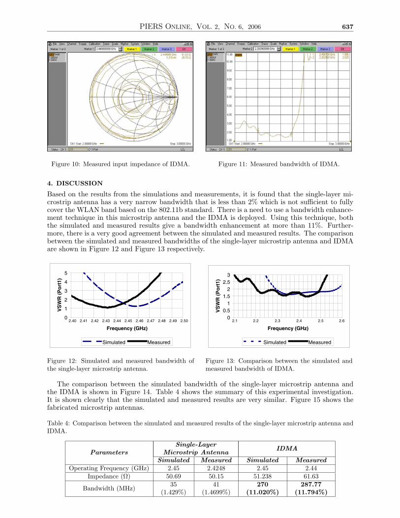
Figure 10: Measured input impedance of IDMA. Figure 11: Measured bandwidth of IDMA.
4. DISCUSSION
Based on the results from the simulations and measurements, it is found that the single-layer mi-crostrip antenna has a very narrow bandwidth that is less than 2% which is not sufficient to fullycover the WLAN band based on the 802.11b standard. There is a need to use a bandwidth enhance-ment technique in this microstrip antenna and the IDMA is deployed. Using this technique, boththe simulated and measured results give a bandwidth enhancement at more than 11%. Further-more, there is a very good agreement between the simulated and measured results. The comparisonbetween the simulated and measured bandwidths of the single-layer microstrip antenna and IDMAare shown in Figure 12 and Figure 13 respectively.
0
1
2
3
4
5
2.40 2.41 2.42 2.43 2.44 2.45 2.46 2.47 2.48 2.49 2.50
Frequency (GHz)
VS
WR
(P
ort
1)
Simulated Measured
Figure 12: Simulated and measured bandwidth ofthe single-layer microstrip antenna.
0
0.5
1
1.5
2
2.5
3
2.1 2.2 2.3 2.4 2.5 2.6
Frequency (GHz)
VS
WR
(P
ort
1)
Simulated Measured
Figure 13: Comparison between the simulated andmeasured bandwidth of IDMA.
The comparison between the simulated bandwidth of the single-layer microstrip antenna andthe IDMA is shown in Figure 14. Table 4 shows the summary of this experimental investigation.It is shown clearly that the simulated and measured results are very similar. Figure 15 shows thefabricated microstrip antennas.
Table 4: Comparison between the simulated and measured results of the single-layer microstrip antenna andIDMA.
ParametersSingle-Layer
Microstrip AntennaIDMA
Simulated Measured Simulated MeasuredOperating Frequency (GHz) 2.45 2.4248 2.45 2.44
Impedance (Ω) 50.69 50.15 51.238 61.63
Bandwidth (MHz)35
(1.429%)41
(1.4699%)270
(11.020%)287.77
(11.794%)

PIERS ONLINE, VOL. 2, NO. 6, 2006 638
0
1
2
3
2.1 2.2 2.3 2.4 2.5 2.6
Frequency (GHz)V
SW
R (
Po
rt 1
)
Single-Layer MSA IDMA
Figure 14: Comparison of the simulated bandwidth.
Air Gap
(a)
(b)
Single layer
IDMA
(c)
Figure 15: The fabricated microstrip antenna (a) side view of IDMA, (b) top view of IDMA and (c) single-layer microstrip antenna and IDMA.
5. CONCLUSION
The technique for enhancing bandwidth of the Microstrip antenna has been shown and it can beused for WLAN applications as it fully utilizes the entire 2.4GHz–2.5 GHz band. As mentioned,this technique has its advantages such as it does not increase the lateral size of the microstripantenna and disadvantages such as it increases the height of the microstrip antenna. Therefore,trade-off issues need to be considered in this design.
REFERENCES
1. Ramesh, G., B. Prakash, B. Inder, and I. Apisak, Microstrip Antenna Design Handbook, ArtechHouse, Inc, USA, 2001.

PIERS ONLINE, VOL. 2, NO. 6, 2006 639
2. Yoharaaj, D., R. S. Azmir, and A. Ismail, “A new approach for bandwidth enhancementtechnique in microstrip antenna for wireless applications,” International RF and MicrowaveConference, RFM06, Putrajaya, Malaysia, 12–14 September 2006.
3. Nirun, K., N. Chalermpol, and T. Taspong, “Parametric study of the rectangular microstripantenna with an air gap,” R&D Journal, Vol. 24, No. 2, King Mongkut’s University of Tech-nology Thonburi, 131-142, Bangkok, May–August 2001.
4. Jackson, D. R. and N. Alexopoulos, “Simple approximate formulas for input resistance, band-width and efficiency of a resonant rectangular patch,” IEEE Transactions on Antennas andPropagation, Vol. 39, 409, March 1991.
5. Balanis, C. A., Antenna Theory: Analysis and Design, John Wiley & Sons, Inc, USA, 2005.