bamboo based cowshed
TRANSCRIPT

7/27/2019 Bamboo based cowshed
http://slidepdf.com/reader/full/bamboo-based-cowshed 1/47
I
ANALYSIS AND DESIGN OFBAMBOO BASED COWSHED
Submitted By:
Deepti Chauhan
(2008CE10260)
Under supervision of
Dr. Suresh Bhalla
A report of CED 412 - Project Part 2 submitted in partial fulfilment
of the requirements of the degree of Bachelor of Technology
Department of Civil Engineering
Indian Institute of Technology, Delhi
April, 2012
7/27/2019 Bamboo based cowshed
http://slidepdf.com/reader/full/bamboo-based-cowshed 2/47
II
CERTIFICATE
I do certify that this report explains the work carried out by me in the Course CED
412 - Project Part 2 under the overall supervision of Dr. Suresh Bhalla. The contents
of the report including text, figures, tables, computer programs, etc. have not been
reproduced from other sources such as books, journals, reports, manuals, websites,
etc. Wherever limited reproduction from another source had been made the source
had been duly acknowledged at that point and also listed in the References.
Deepti Chauhan
Date: 30 Apr, 2012
7/27/2019 Bamboo based cowshed
http://slidepdf.com/reader/full/bamboo-based-cowshed 3/47
III
CERTIFICATE
This is to certify that the report submitted by Deepti Chauhan (2008CE10260)
describes the work carried out by her in the course Course CED 412 - Project Part 2
under my overall supervision.
Dr. Suresh Bhalla
(Supervisor)
Date: 30 Apr, 2012

7/27/2019 Bamboo based cowshed
http://slidepdf.com/reader/full/bamboo-based-cowshed 4/47
IV
ACKNOWLEDGEMENT
I would like to express my sincere thanks and gratitude to Dr. Suresh Bhalla for his
continuous and unfailing support, guidance and help, which have been invaluable
during the course of this project. His knowledge, insight and constant motivation at
each step of the project has been instrumental in its completion.
I would like to take this opportunity to thank the entire staff at StructuresLaboratory and the Civil Engineering Laboratory for their cooperation and
assistance in the lab-work that was required for this project.
Deepti Chauhan
7/27/2019 Bamboo based cowshed
http://slidepdf.com/reader/full/bamboo-based-cowshed 5/47
V
ABSTRACT
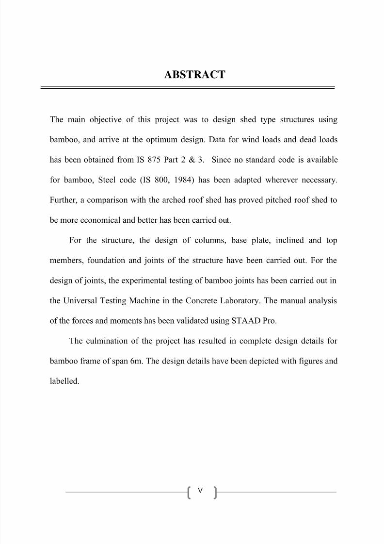
The main objective of this project was to design shed type structures using
bamboo, and arrive at the optimum design. Data for wind loads and dead loads
has been obtained from IS 875 Part 2 & 3. Since no standard code is available
for bamboo, Steel code (IS 800, 1984) has been adapted wherever necessary.
Further, a comparison with the arched roof shed has proved pitched roof shed to
be more economical and better has been carried out.
For the structure, the design of columns, base plate, inclined and top
members, foundation and joints of the structure have been carried out. For the
design of joints, the experimental testing of bamboo joints has been carried out in
the Universal Testing Machine in the Concrete Laboratory. The manual analysis
of the forces and moments has been validated using STAAD Pro.
The culmination of the project has resulted in complete design details for
bamboo frame of span 6m. The design details have been depicted with figures and
labelled.
7/27/2019 Bamboo based cowshed
http://slidepdf.com/reader/full/bamboo-based-cowshed 6/47
VI
TABLE OF CONTENTS
Chapter 1 BUILDINGS ....................................................................................................................... 1
1.1 INTRODUCTION .................................................................................................................................... 1
1.2 DIFFERENT COMPONENTS OF A BUILDING .......................................................................................... 1
1.2.1 Roofing and wall material ............................................................................................................. 1
1.2.2 Bay width ...................................................................................................................................... 2
1.2.3 Structural Framing ........................................................................................................................ 2
1.2.4 Purlins, Girts and Eave strut .......................................................................................................... 2
1.2.5 Spacing of Purlins .......................................................................................................................... 3
1.2.6 Plane Trusses................................................................................................................................. 3
1.2.7 Spacing of trusses ......................................................................................................................... 3
1.3 LOAD COMBINATIONS FOR DESIGN .................................................................................................... 4
1.4 WHY BAMBOO AS A CONSTRUCTION MATERIAL? ............................................................................... 4
Chapter 2 DESIGN PHILOSOPHY .................................................................................................... 6
2.1 STRUCTURAL DETAILS AND BASIC BAMBOO ELEMENTS ...................................................................... 6
2.2 DESIGN PHILOSOPHY AND ALLOWABLE STRESSES .............................................................................. 6
2.3 DEAD LOADS AND IMPOSED LOADS ..................................................................................................... 7
2.4 WIND LOADS ........................................................................................................................................ 7
2.5 DESIGN OF COLUMNS .......................................................................................................................... 9
2.6 DESIGN OF BASE PLATE ........................................................................................................................ 9
2.7 DESIGN OF FOUNDATION .................................................................................................................. 10
2.8 DESIGN OF INCLINED MEMBERS AND TOP CHORD ........................................................................... 10
2.9 DESIGN OF JOINTS .............................................................................................................................. 11
2.10 COMPARISON OF PITCHED AND ARCHED ROOF .............................................................................. 11
Chapter 3 RESULTS AND CALCULATIONS .......................................................................................... 13
3.1 RESULTS FOR BUILDING A (25M×6M×4M) : ...................................................................................... 13
3.1.1 Forces in Column ......................................................................................................................... 13
3.1.2 Design forces in columns: ........................................................................................................... 14
3.1.3 Design of columns of building A: ................................................................................................ 14
3.1.4 Design of Base Plate for Building A ............................................................................................. 15
3.1.4 Design of Foundation for Building A ........................................................................................... 16
7/27/2019 Bamboo based cowshed
http://slidepdf.com/reader/full/bamboo-based-cowshed 7/47
VII
3.1.5 Design of Inclined & Top members for Building A ...................................................................... 19
3.1.6 Design of joints for Building A ..................................................................................................... 19
3.2 RESULTS FOR BUILDING B (25M×8M×4.5M) : ................................................................................... 20
3.2.1 Forces in Column ......................................................................................................................... 20
3.2.2 Design forces in columns: ........................................................................................................... 21
3.2.3 Cross ‐ sections of different components of building B: ............................................................. 21
3.2.4 Design of Base Plate for Building B ............................................................................................. 22
Chapter 4 ANALYSIS VALIDATION USING STAAD ................................................................................ 23
Chapter 5 CONSTRUCTION OF BAMBOO SHED .................................................................................. 24
Chapter 6 EXPERIMENTAL TESTING ................................................................................................. 25
6.1 TEST 1: PLAIN BAMBOO SAMPLE ....................................................................................................... 25
6.2 TEST 2: TYRE‐TUBE RUBBER BAMBOO SAMPLE ................................................................................ 27
6.3 TEST 3: ARALDITE BAMBOO SAMPLE ................................................................................................. 27
6.4 TEST RESULTS ..................................................................................................................................... 29
Chapter 7 CONCLUSIONS AND RECOMMENDATIONS ................................................................. 30
7.1 CONCLUSIONS .................................................................................................................................... 30
7.2 RECOMMENDATIONS FOR FUTURE WORK ........................................................................................ 31
7.3 SOURCES OF ERROR ........................................................................................................................... 31
REFERENCES ................................................................................................................................................. 32
APPENDIX ..................................................................................................................................................... 33

7/27/2019 Bamboo based cowshed
http://slidepdf.com/reader/full/bamboo-based-cowshed 8/47
VIII
LIST OF FIGURES
Figure 1.1 Different Components of an Industrial Building.........................................................4
Figure 2.1 A conventional shed structure made of steel..............................................................6
Figure 2.2 Wind pressure coefficients in accordance with IS 875 part 3......................................8
Figure 2.3 Analysis of transverse frame for wind normal to ridge, inside pressure......................9
Figure 2.4 I-bolt joint...................................................................................................................11
Figure 2.5 Joint connection with I-bolt joint and gusset plate.....................................................11
Figure 2.6 Arched-roof Bamboo shed..........................................................................................12
Figure 3.1 Cross sections of column component of building A...................................................14Figure 3.2 Sample column for testing constructed using 4 bamboo struts...................................15
Figure 3.3 Base plate of column for building A............................................................................15
Figure 3.4 Foundation Layout Plan for Building A......................................................................16
Figure 3.5 Foundation Details for Building A in Plan..................................................................17
Figure 3.6 Reinforcement Details for Pedestal of Building A in Plan..........................................17
Figure 3.7 Foundation details of Building A in Elevation............................................................18
Figure 3.8 Details of Bolt for Pedestal of Building A...................................................................18
Figure 3.9 Cross section of inclined member of Building A.........................................................19
Figure 3.10 Joints connecting base of column and base plate.......................................................19
Figure 3.11 Cross sections of column of building B ...................................................................... 21
Figure 3.12 Base plate of column for building B............................................................................ 22
Figure 5.1 Sketch for Construction of Bamboo Frame..................................................................25
Figure 6.1 Simple Bamboo sample ................................................................................................. 25
Figure 6.2 Friction Joint of Bamboo sample .................................................................................. 25
Figure 6.3 Testing of Simple Bamboo sample................................................................................ 26
Figure 6.4 Failure of Simple Bamboo sample ................................................................................ 26
Figure 6.5 Failure of Tube-Tyre Rubber Bamboo sample .............................................................. 27
Figure 6.6 Friction Joint of Araldite Bamboo sample .................................................................... 27
Figure 6.7 Testing of Araldite Bamboo sample .............................................................................. 28
Figure 6.8 Failure of Araldite Bamboo sample .............................................................................. 28

7/27/2019 Bamboo based cowshed
http://slidepdf.com/reader/full/bamboo-based-cowshed 9/47
IX
LIST OF TABLES
TABLE 2.1 Comparison of design forces in Arched Roof and Pitched Roof Frame
TABLE 3.1 Summary of forces at base of column for Building A
TABLE 3.2 Summary of design forces in column for Building A
TABLE 3.3 Summary of forces at base of column for Building B
TABLE 3.4 Summary of design forces in column for Building B
TABLE 4.1 Comparison of design forces in column
TABLE 6.1 Load taken by the test samples
TABLE 6.2 Load taken by the new test samples
7/27/2019 Bamboo based cowshed
http://slidepdf.com/reader/full/bamboo-based-cowshed 10/47
1
Chapter 1 BUILDINGS
1.1 INTRODUCTION
High rise steel buildings account for a very small percentage of the total number of structures
that are built around the world. The majority of steel structures being built are low rise
buildings, which are generally of one storey only. Industrial buildings, a subset of low-rise
buildings are normally used for steel plants, automobile industries, utility and process industries,
thermal power stations, warehouses, assembly plants, stores, garages, small scale industries, etc.
These buildings require large column free areas. Hence interior columns, walls, and partitions are
often eliminated or kept to a minimum. Most of these buildings may require adequate head room
for the use of an overhead travelling crane.
1.2 DIFFERENT COMPONENTS OF A BUILDING
The structural engineer has to consider the following points during the planning and design of
buildings:
i. Selection of Roofing and wall material
ii. Selection of bay width
iii. Selection of structural framing system
iv. Roof trusses
v. Purlins, grits and sag rods
vi. Bracing systems to resist lateral loads
vii. Gantry girders, columns, base plates, and foundations
1.2.1 Roofing and wall material
In India, corrugated galvanized iron (GI) sheets are usually adopted as coverings for roofs and
sides of industrial buildings. Light gauge cold-formed ribbed steel or aluminium decking
7/27/2019 Bamboo based cowshed
http://slidepdf.com/reader/full/bamboo-based-cowshed 11/47
2
can also be used. Sometimes asbestos cement (AC) sheets are also provided as roof coverings
owing top their superior insulating properties.
1.2.2 Bay width
In most cases, the bay width may be indicated by owner requirements. Gravity loads generally
control the bay size. Based on both strength and stiffness (L/180) requirements, the maximum
economical span is 9m.
1.2.3 Structural
Framing
For the purpose of structural analysis and design, industrial buildings are classified as:
• Braced frames
• Unbraced frames
In braced buildings, the trusses rest on columns with hinge type of connections and the stability
is provided by bracings in the three mutually perpendicular planes. These bracings are identified
as follows:
a. Bracings in the vertical plane in the end bays in the longitudinal direction
b. Bracings in the horizontal plane at bottom chord level of the roof truss
c. Bracings in the plane of upper chords of the roof truss
d. Bracings in the vertical plane in the end cross sections usually at the gable ends.
1.2.4 Purlins, Girts and Eave strut
Secondary structural members such as purlins and girts span the distance between the primary
building structures portal frames or truss-column system). They support the roof and wall
covering and distribute the external load to the main frames or trusses. Purlins form a part of the
roof bracing system and girts are a part of the wall bracing system of the building. The third type
of secondary structural member is the Eave strut. This member is located at the intersection of
the roof and the exterior wall and hence acts as both the first purlin and the last (highest) girt.
The building s eave height is measured to the top of this member.

7/27/2019 Bamboo based cowshed
http://slidepdf.com/reader/full/bamboo-based-cowshed 12/47
3
1.2.5 Spacing of Purlins
The spacing of the purlins largely depends on the maximum safe span of the roof covering and
glazing sheets. Hence they should be less than or equal to their safe spans when they are directly
placed on purlins.
1.2.6 Plane Trusses
A structure that is composed of a number of line members pin-connected at the ends to form a
triangulated framework is called a truss. In a truss, the members are so arranged that all the loads
and reactions occur only at the joints (intersection point of the members). For common trusses
with vertically acting loads, compressive forces are usually developed in the top chord members
and tensile forces in the bottom chord members. However, it is often necessary to design the
various members of a truss both for tension and compression and select the member size based
on the critical force.
1.2.7 Spacing of trusses
The spacing of trusses is mostly determined by the spacing of supporting columns which in turnis determined by the functional requirements. When there are no functional requirements, the
spacing should be such that the cost of the roof is minimized. It can be shown that an economic
system is obtained when the cost of trusses is equal to the cost of roof covering plus twice the
cost of purlins. i.e.
Ct = Cr + 2C p ...... (1.1)
where
Ct = Cost of the trusses/unit area
Cr = Cost of the roof coverings/unit area
C p = Cost of the purlins/unit area

7/27/2019 Bamboo based cowshed
http://slidepdf.com/reader/full/bamboo-based-cowshed 13/47
1.3 L
For sh
crane l
1. De
2 De
whiche
4. De
The 3rd
pressur
1.4 W Constr
concret
constit
burnin
carbon
related
produc
atmosp
AD COMd type bui
ad:
d loads + i
d loads +
er is sever
d loads + i
combinati
e separatel
Y BAMBction indu
e and stee
ent of co
fossil fuel
dioxide (C
to the ma
ion of ever
ere (Ghav
INATIO
dings, the
posed loa
wind load
e)
posed loa
n is consid
to determi
Figure
OO AS A try is one
l causes c
crete, req
s. Produci
2) (CS M
ufacture a
y ton of st
mi, 2007).
S FOR Dfollowing
ds (live loa
s (wind di
ds + wind l
ered with i
ne the wor
.1 Differe
ONSTRU
of the mo
onsiderabl
ires heatin
g every to
onitor, 200
d transpor
el is acco
4
ESIGN ombinatio
ds)
rection bei
oads (whic
ternal posi
t combinat
t Compo
CTION Mst pollutin
deteriorat
g limeston
of cemen
). Roughl
ation of ce
panied wi
s of loads
g normal
may not b
ive air pre
on of wind
ents of an
TERIAL
industries
ion of the
and othe
results in
5 to 10 p
ment (Scie
h the relea
are consi
to ridge o
e critical i
sure and i
load.
Industrial
in the wo
environm
ingredie
the emissi
rcent of gl
ntific Ame
se of over
ered when
r parallel
most of th
ternal sucti
Building
rld. Produc
nt. Ceme
ts to over
n of at lea
bal CO2 e
rican, 200
two tons o
there is n
o ridge
e cases).
on air
tion of bo
t, the mai
1,400oC b
t one ton
missions a
). Similarl
CO2 in t
h
n
y
f
e
,
e
7/27/2019 Bamboo based cowshed
http://slidepdf.com/reader/full/bamboo-based-cowshed 14/47
5
The project presents the possible replacement of concrete and steel by eco-friendly bamboo as a
modern engineering construction material. In fact, growth of every ton of bamboo consumes
nearly a ton of carbon dioxide besides releasing fresh oxygen into the atmosphere. In this project,
through structural analysis and design principles, it is demonstrated as to how modern engineered
structures can be a real possibility using bamboo. A detailed structural analysis and design of a
typical bamboo shed structure is presented in accordance with the Indian standard codes of
practice. The columns are designed as battened columns with concrete bands as the ties. The roof
is designed as a bamboo parabolic tied arch resting on the battened bambcrete columns. Other
elements such as purlins and bracings are also bamboo based. Not only the proposed structure is
capable of withstanding the loads as prescribed in the codes of practice, its cost is several timesless than the so called modern structures constructed using concrete and steel. The details
presented in this project set aside the conventional belief that only concrete and steel structures
can be engineered. Modern structural analysis and design practices can be suitably applied upon
bamboo elements for rational engineering design of buildings and other structures.
While acknowledging the need for building more structures, it is also most important to keep the
environmental issues at the forefront. It is here that engineered bamboo can be of great value to
civil engineers owing to several noteworthy features. From structural engineering point of view,
bamboo has competitive strength characteristics. Typically, species like dendrocallamus
giganteus (DG) have tensile strength of about 120 MPa, compressive strength of 55 MPa and
Young s modulus of 14 GPa. These figures do not compare badly with mild steel which has an
ultimate strength of 410 MPa, yield strength of 250 MPa and Young s modulus of 200 GPa.
Concrete has much lower strength than those of bamboo reported here. In addition, the low
density of bamboo, which is typically 700kg/m3, results in much higher strength to weight ratio as
compare to steel (density = 7800 kg/m3) and concrete (density = 2400 kg/m3). The only
shortcoming with raw bamboo is susceptibility to termite attack which can be set aside by suitable
chemical treatment.

7/27/2019 Bamboo based cowshed
http://slidepdf.com/reader/full/bamboo-based-cowshed 15/47
6
Chapter 2 DESIGN PHILOSOPHY 2.1 STRUCTURAL DETAILS AND BASIC BAMBOO ELEMENTS
At present, no book or code of practice is available for design of bamboo structures on scientific
lines. The first attempt in this direction was made by Bhalla et al. (2008). In order to explain the
design procedure, two shed type structures, 25m×6m in plan and 4.5m in height, and 25m×8m
in plan and 5.5m in height have been designed using engineered bamboo. The structure isassumed to be situated in Delhi region. Fig. 2.1 shows the front and the side elevations of a
conventional industrial shed made of steel. In the alternative design presented here, the steel
columns shall be replaced by battened bamboo columns, where bamboo elements serve as struts
embedded in a steel base plate. The steel roof truss shall be replaced by bamboo pitched roof. The
pitched roof has a height of 2.5 m and span of 8m. Both the columns and the pitched roof will be
constructed with the combination of bamboo and steel elements.
Figure 2.1 A conventional shed structure made of steel
2.2 DESIGN PHILOSOPHY AND ALLOWABLE STRESSES
The design covered in this project is assumed to use the species dendrocallamus giganteus (DG)
of bamboo, for which the tensile strength and the compressive strengths are reported as
121.5MPa and 55.55 MPa respectively (Ghavami, 2007). However, the recent tests carried out
7/27/2019 Bamboo based cowshed
http://slidepdf.com/reader/full/bamboo-based-cowshed 16/47
7
in the laboratory have resulted in an increased compressive strength of 61 MPa (Shaw A.,
2012). The proposed approach follows the working stress design method and assumes that
bamboo behaves linearly elastic in the working stress range. Being natural product, and
expecting a large variation of strength characteristics, a large factor of safety of 3.5 is considered
in the proposed approach. According to IS 800 (1984), the permissible stress in tension works
out to be 16 MPa. For compression, by taking the factor of safety and the elastic critical stress,
the allowable compressive stress works out to be 11 MPa for a slenderness ratio of 80. Each
bamboo element is considered to have an external diameter of 40mm and a wall thickness of
10mm.
2.3 DEAD LOADS AND IMPOSED LOADS
Dead load and imposed load analysis of the structure are straightforward since these loads do not
induce any moment on the column due to flexible connection of the bamboo arch with the
columns. For dead loads, the roof has been considered to be covered by galvanized iron (GI)
sheeting. These are considered to impose a dead load of 0.25kN/m2. The density of bamboo is
assumed to be equal to 7kN/m3
. In accordance with IS 875 part 2, an imposed load of 0.75kN/m2
has been considered for the roof .
2.4 WIND LOADS
In this study, the structure is analyzed for wind forces in accordance with IS: 875 Part 3. For
Delhi region, this code recommends a basic wind speed V b of 47m/s. This study has considered
the value of the probability factor (risk coefficient) k 1 as1.0 assuming a mean probable life of 50
years. The terrain, height and size factor k 2 of 1.0 has been considered since the proposed
structure belongs to class A and category 2 as per IS 875 part 3. Finally, the topography factor k 3
has been chosen as 1.0. These factors result in a design wind speed V Z (= k 1 k 2 k 3 V b ) of 47m/s ,
thereby resulting in a design wind pressure of 1.325 kN/m2
(= 0.6V z2). The external and internal
pressure coefficients on the wall and roof in accordance with IS 875 Part 3 are shown in Fig. 2.2
for two wind directions - normal to the ridge and parallel to the ridge. An internal wind pressure

7/27/2019 Bamboo based cowshed
http://slidepdf.com/reader/full/bamboo-based-cowshed 17/47
8
of ±0.7 has been considered. In overall, following wind cases have been analyzed:
1. Wind normal to ridge, inside suction.
2. Wind normal to ridge, inside pressure.
3. Wind along ridge, inside suction.
4. Wind along ridge, inside pressure.
Figure 2.2 Wind pressure coefficients in accordance with IS 875 part 3
Fig. 2.3 shows the steps involved in the analysis of a typical transverse frame, which supports the
wind load on a tributary length of 5m of the building, for the case of wind load normal to ridge
with pressure inside. The structure is analyzed as the superposition of two cases- (A) and (B),
shown in the figure. The columns are idealized as propped cantilevers for case (A).

7/27/2019 Bamboo based cowshed
http://slidepdf.com/reader/full/bamboo-based-cowshed 18/47
9
Figure 2.3 Analysis of transverse frame for wind normal to ridge, inside pressure
2.5 DESIGN OF COLUMNS
For the design of Columns, the moment acting at the base of the columns is considered as a
couple of forces, compressive and tensile. The total load (dead + imposed) acting on each
column is calculated and the net compressive and tensile force acting on the column is
calculated, and then the column is designed for the critical force. The number of bamboo struts
may also be governed by the slenderness ratio (which is limited to 200 for all the compression
members for bamboo). The local slenderness ratio is kept limited to 80 by having stirrups atregular distances. The column, thus designed, is using bamboo struts and the formula:
σ = P/A + M/Z ... (2.1)
2.6 DESIGN OF BASE PLATE
The base plate has been designed assuming stiff connection between the bamboo struts and the
base plate. The moment from the bamboo struts is transferred to the base plate using gusset platesand joints. The base plate has been designed assuming M30 concrete foundation. With
calculations for forces and moments, the size of the base plate and the number of bolts required
has been calculated. The following equations were used for calculating the thickness of the base
plate
P + T = 0.36 f ck b xu ... (2.2)
P*d + M = 0.36 f ck b xu (L/2 + d – 0.416 xu) ... (2.3)

7/27/2019 Bamboo based cowshed
http://slidepdf.com/reader/full/bamboo-based-cowshed 19/47
10
2.7
DESIGN
OF
FOUNDATION
The foundation has been designed as isolated footings of reinforced concrete (RC). Usual
design principles followed for footing design (considering the bending moment, one-way shear
and two- way shear) have been used. The footing has been designed assuming M30 concrete.
The allowable load has been calculated for the footing using:
Under normal conditions: qall, gross = qall, net + q ... (2.4)
Under wind/earthquake: qall,gross = 1.25 qall,net + q ... (2.5)
Then the total load and moment for the footing are calculated:Pt = P + Overburden ... (2.6)
Mt = M + H*(Footing thickness) ... (2.7)
Thereafter, the stress requirements are checked:
σmax = Pt/A + Mt/Z ... (2.8)
σmin = Pt/A – Mt/Z ... (2.9)
The moment for the foundation is calculated and reinforcement is calculated. Also, the footing
is then checked for one way, two way shear, sliding and overturning.
2.8 DESIGN OF INCLINED MEMBERS AND TOP CHORD
The design of inclined chord members is similar to that of the columns. It is calculated using the
total force and moment acting on the member and is distributed among the various bamboo
members. First of all, the load intensity due to dead loads (w1) has been calculated and then
the calculation of load intensity due to wind loads (w2) has been done. After calculating the
load intensities, the load intensity w1 has been resolved in two directions, one parallel to axis of
member and another normal to it. After computation of the maximum moment, a suitable
section of the bamboo struts is considered and the sectional properties (I, Z) of the section
are calculated. Similarly, the top horizontal chord of the structure is designed. Spliced sections
of bamboo are used. Again, the design of the member is governed by the slenderness ratio
criteria.
7/27/2019 Bamboo based cowshed
http://slidepdf.com/reader/full/bamboo-based-cowshed 20/47
11
2.9 DESIGN OF JOINTS
The joints for the base of the columns are designed to transfer forces and moments to the base
plate and the footing. The joints are designed with clamps on either side tightened to hold the
bamboo strut. The base joints are designed to make use of the shear and friction bearing capacity
of the bamboo strut. Further, the various joints are connected to the base plate and connected with
each other through welding. The formula used for calculating the weld size for the base plate is as
follows:
f e = √(f a2 + 3q
2) < f u/((√3)γmw) ... (2.10)
Further, apart from the joints at the base, the joints on top of the column and at the roof are
designed to be pin joints. Bamboo struts at the top of the column are connected together using a
gusset plate and then the gusset plate is connected to the inclined members using I-bolts joints.
Figure 2.4 I-bolt joint Figure 2.5 Joint connection with I-bolt
joint and gusset plate
2.10 COMPARISON OF PITCHED AND ARCHED ROOF
Previous work has also been carried in the same field (Korde, 2012). Analysis and design was
carried out on such structural frame of Bamboo structure with an arched roof.

7/27/2019 Bamboo based cowshed
http://slidepdf.com/reader/full/bamboo-based-cowshed 21/47
12
Figure 2.6 Arched-roof Bamboo shed
However, the forces are much higher in the case of arched roof as compared to that of the present
analysis with a pitched roof. The comparison of the forces for a bamboo frame of 6m span is
given in Table 2.1.
TABLE 2.1 Comparison of design forces in Arched Roof and Pitched Roof Frame
Tensile (KN) Moment (KNm) Horizontal (KN)
Arch Pitched Arch Pitched Arch Pitched
Case 1
Wind normal,
inside pressure
31.81 14.78 25.37 19.2 18.85 18.92
Case 2
Wind normal,
inside suction
3.98 -8.25 29.43 16.67 24.64 19.47
Case 3
Wind along,
inside pressure
27.83 23.09 12.18 8.49 17.4 14.91
Case 4Wind along,
inside suction
0 0 20.3 1.49 2.9 2.48
It can be seen that the forces and moments in the pitched-roof frame are less than those in the
arched-roof frame. Hence, the pitched roof structure is economical and better than the arched-roof
structure.
7/27/2019 Bamboo based cowshed
http://slidepdf.com/reader/full/bamboo-based-cowshed 22/47
13
Chapter 3 RESULTS AND CALCULATIONS The complete design of two bamboo sheds has been manually done. The plan area for the two
buildings was taken as 25m×6m and 25m×8m. The total height of the two buildings has been
considered as 5m (3m column height and 2m pitched roof height) and 5.5m (3m column height
and 2.5m pitched roof height) respectively. The frame spacing has been taken as 5m for both the
buildings.
3.1 RESULTS FOR BUILDING A (25M×6M×4M) :
3.1.1 Forces
in
Column
The summary of forces at the bottom of column for the four different wind conditions as
computed for building A is displayed in Table 3.1:
TABLE 3.1 Summary of forces at base of column
S.No. Wind Case Tensile Force
(KN)
Moment
(KN-m)
Horizontal Force
(KN)
1 Wind Normal to ridge,
inside suction
-3.25 16.67 19.47
2 Wind Normal to ridge,
inside pressure
14.28 19.2 18.92
3 Wind parallel to ridge,
inside suction
0 1.49 2.48
4 Wind parallel to ridge,
inside pressure
23.09 8.49 14.91

7/27/2019 Bamboo based cowshed
http://slidepdf.com/reader/full/bamboo-based-cowshed 23/47
14
3.1.2 Design forces in columns:
Using Table 3.1, design forces in columns have been calculated for two different cases.
TABLE 3.2 Summary of design forces in column
S.No. Load Combination Bending Moment
(KN-m)
Axial Force
(KN)
1 Dead Load + Wind Case 1 16.67 18.25 (C)
2 Dead Load + Wind Case 2 19.2 0.22 (C)
3 Dead Load + Wind Case 3 1.49 15 (C)
4 Dead Load + Wind Case 4 8.49 8.09 (T)
3.1.3 Design of columns of building A:
Based on the design forces on the columns and the allowable stress for bamboo, the columns
have been designed. Here, the concentric circles represent the bamboo struts. For example,
Figure 3.1 shows that a section of 400mm×400mm consisting of six bamboo struts is
suitable for the column.
Figure 3.1 Cross sections of column component of building A
400 mm
200 mm
200 mm
7/27/2019 Bamboo based cowshed
http://slidepdf.com/reader/full/bamboo-based-cowshed 24/47
15
A similar column on the same lines has been constructed at IIT Delhi with 4 bamboo struts.
Figure 3.2 shows a sample column constructed at IIT Delhi and then tested at Trinity College,
Dublin, Ireland.
Figure 3.2 Sample column for testing constructed using 4 bamboo struts
3.1.4 Design of Base Plate for Building A
The base plate for Building A is designed for 6 bamboo strut columns. The bamboo struts are
further connected with each other with the use of gusset plates. Further the joints are welded to
each other. The various joints of bamboo struts are welded together and the calculated weld size
is 8 mm.
Figure 3.3 Base plate of column for building A
500 mm
500 mm
4 – 16mm
bolts

7/27/2019 Bamboo based cowshed
http://slidepdf.com/reader/full/bamboo-based-cowshed 25/47
16
3.1.4 Design of Foundation for Building A
The foundation has been designed as isolated footings of reinforced concrete (RC). Usualdesign principles followed for footing design (considering the bending moment, one-way shear
and two- way shear) have been used. The foundation layout plan for the whole building is in
Figure 3.3.
Figure 3.4 Foundation Layout Plan for Building A
A B
2
3
4
5
6
F
PF
F
P
F
P
FP
FP
F
P
F
P
F
P
F
P
FF
6m
5m
25m
7/27/2019 Bamboo based cowshed
http://slidepdf.com/reader/full/bamboo-based-cowshed 26/47
17
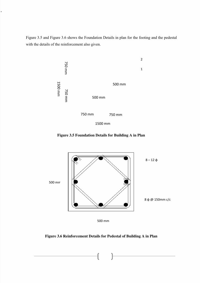
Figure 3.5 and Figure 3.6 shows the Foundation Details in plan for the footing and the pedestal
with the details of the reinforcement also given.
Figure 3.5 Foundation Details for Building A in Plan
Figure 3.6 Reinforcement Details for Pedestal of Building A in Plan
500 mm
500 mm
8 – 12 φ
8 φ @ 150mm c/c
500 mm
500 mm
1 5 0 0 m m
7 5 0 m m
7 5 0 m m
1500 mm
750 mm 750 mm
2
1
7/27/2019 Bamboo based cowshed
http://slidepdf.com/reader/full/bamboo-based-cowshed 27/47
18
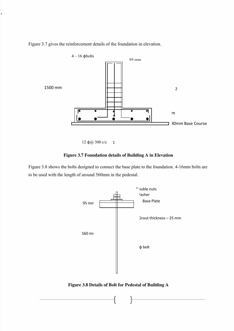
Figure 3.7 gives the reinforcement details of the foundation in elevation.
Figure 3.7 Foundation details of Building A in Elevation
Figure 3.8 shows the bolts designed to connect the base plate to the foundation. 4-16mm bolts are
to be used with the length of around 560mm in the pedestal.
Figure 3.8 Details of Bolt for Pedestal of Building A
12 φ@ 300 c/c
10 φ@ 300 c/c8 φ@ 150 c/c
4 – 16 φ bolts
560 mm
95 mm
Washer
560 mm
95 mm
16 ɸ bolt
Double nuts
Base Plate
Grout thickness – 25 mm
1500 mm
300 mm
80mm Base Course
2
1

7/27/2019 Bamboo based cowshed
http://slidepdf.com/reader/full/bamboo-based-cowshed 28/47
19
3.1.5 Design of Inclined & Top members for Building A
For the inclined members, the bamboo struts are tied by stirrups at a regular spacing of 500mmin order to limit the local slenderness ratio to 80, as mentioned earlier. The inclined members
constitute of 4 bamboo struts each at a distance of 300mm. Similarly, the top horizontal chord
of the structure is designed. Spliced sections of bamboo are used.
Figure 3.9 Cross section of inclined member of Building A
3.1.6 Design of joints for Building A
Apart from the I-bolt joints discussed for the pin joint connections, the joints at the base are
designed with clamps on either side tightened to hold the bamboo strut. The base joints are
designed to make use of the shear and friction bearing capacity of the bamboo strut.
Figure 3.10 Joints connecting base of column and base plate
300 mm
300 mm
7/27/2019 Bamboo based cowshed
http://slidepdf.com/reader/full/bamboo-based-cowshed 29/47
20
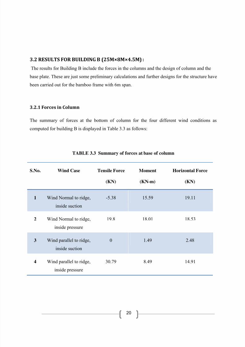
3.2 RESULTS
FOR
BUILDING
B
(25M×8M×4.5M)
:
The results for Building B include the forces in the columns and the design of column and the
base plate. These are just some preliminary calculations and further designs for the structure have
been carried out for the bamboo frame with 6m span.
3.2.1 Forces in Column
The summary of forces at the bottom of column for the four different wind conditions ascomputed for building B is displayed in Table 3.3 as follows:
TABLE 3.3 Summary of forces at base of column
S.No. Wind Case Tensile Force
(KN)
Moment
(KN-m)
Horizontal Force
(KN)
1 Wind Normal to ridge,
inside suction
-5.38 15.59 19.11
2 Wind Normal to ridge,
inside pressure
19.8 18.01 18.53
3 Wind parallel to ridge,
inside suction
0 1.49 2.48
4 Wind parallel to ridge,
inside pressure
30.79 8.49 14.91

7/27/2019 Bamboo based cowshed
http://slidepdf.com/reader/full/bamboo-based-cowshed 30/47
21
3.2.2 Design
forces
in
columns:
Using Table 3.4, design forces in columns have been calculated for two different cases.
TABLE 3.4 Summary of design forces in column
S.No. Load Combination Bending Moment
(KN-m)
Axial Force
(KN)
1 Dead Load + Wind Case 1 16.67 18.25 (C)
2 Dead Load + Wind Case 2 19.2 0.22 (C)
3 Dead Load + Wind Case 3 1.49 15 (C)
4 Dead Load + Wind Case 4 8.49 8.09 (T)
3.2.3 Cross ‐ sections of different components of building B:
Based on the design forces on the columns and the allowable stress for bamboo, the columns
have been designed. Here, the concentric circles represent the bamboo struts. For example,
Figure 3.3 shows that a section of 400mm×400mm consisting of ten bamboo struts is
suitable for the column.
Figure 3.11 Cross sections of column of building B
400 mm
200 mm
200 mm
7/27/2019 Bamboo based cowshed
http://slidepdf.com/reader/full/bamboo-based-cowshed 31/47
22
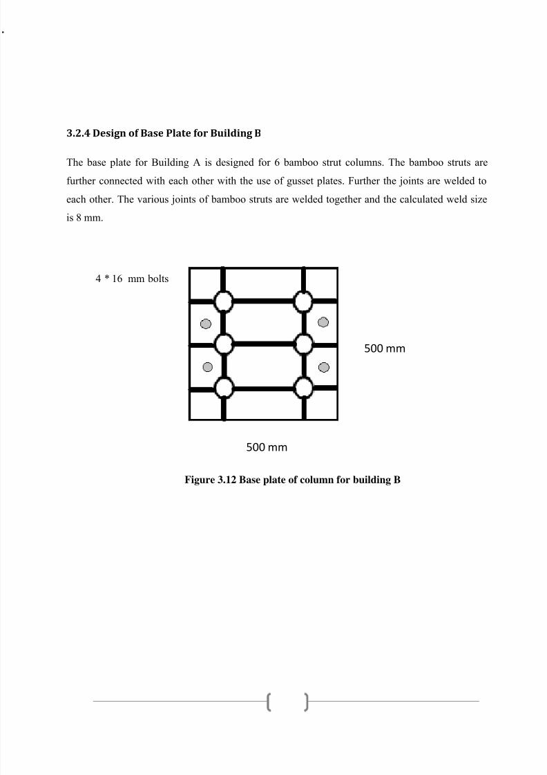
3.2.4 Design
of
Base
Plate
for
Building
B
The base plate for Building A is designed for 6 bamboo strut columns. The bamboo struts are
further connected with each other with the use of gusset plates. Further the joints are welded to
each other. The various joints of bamboo struts are welded together and the calculated weld size
is 8 mm.
Figure 3.12 Base plate of column for building B
4 * 16 mm bolts
500 mm
500 mm

7/27/2019 Bamboo based cowshed
http://slidepdf.com/reader/full/bamboo-based-cowshed 32/47
23
Chapter 4 ANALYSIS VALIDATION USING STAAD The manual analysis carried out for the force and moments of the structural bamboo frame is
validated by analysing the frame using STAAD Pro. The frame dimensions have been taken to
be 4m in height (with 3m column height and 1m inclined member height) and a span of 6m. The
supports at the base of the columns are fixed joints. The material specified for the analysis is
steel as the results would be similar and the assumptions that bamboo behaves in an elastic
manner as steel holds good.
The results of the STAAD analysis are in accordance with the manual analysis. The resultant
reactions at the base of the columns have been found to be similar to that of the manual results.
The reactions found out have been shown in Table 4.1.
TABLE 4.1 Comparison of design forces in column
Wind along, inside pressure
Column 1
Tensile Moment Horizontal
Manual STAAD Manual STAAD Manual STAAD
23.09 21.014 -8.49 -6.651 -14.91 -12.614
Column 2
Tensile Moment Horizontal
Manual STAAD Manual STAAD Manual STAAD
23.09 21.014 8.49 6.651 14.91 12.614
7/27/2019 Bamboo based cowshed
http://slidepdf.com/reader/full/bamboo-based-cowshed 33/47
24
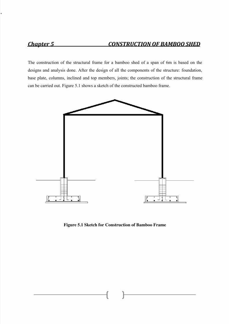
Chapter 5 CONSTRUCTION OF BAMBOO SHED The construction of the structural frame for a bamboo shed of a span of 6m is based on the
designs and analysis done. After the design of all the components of the structure: foundation,
base plate, columns, inclined and top members, joints; the construction of the structural frame
can be carried out. Figure 5.1 shows a sketch of the constructed bamboo frame.
Figure 5.1 Sketch for Construction of Bamboo Frame
3m
1m
6m
7/27/2019 Bamboo based cowshed
http://slidepdf.com/reader/full/bamboo-based-cowshed 34/47
25
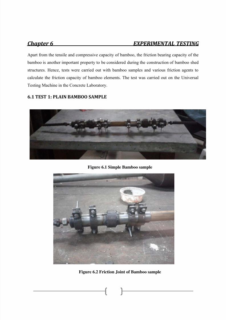
Chapter 6 EXPERIMENTAL TESTING Apart from the tensile and compressive capacity of bamboo, the friction bearing capacity of the bamboo is another important property to be considered during the construction of bamboo shed
structures. Hence, tests were carried out with bamboo samples and various friction agents to
calculate the friction capacity of bamboo elements. The test was carried out on the Universal
Testing Machine in the Concrete Laboratory.
6.1 TEST 1: PLAIN BAMBOO SAMPLE
Figure 6.1 Simple Bamboo sample
Figure 6.2 Friction Joint of Bamboo sample

7/27/2019 Bamboo based cowshed
http://slidepdf.com/reader/full/bamboo-based-cowshed 35/47
26
Figure 6.3 Testing of Simple Bamboo sample
Figure 6.4 Failure of Simple Bamboo sample
Slip at joint
7/27/2019 Bamboo based cowshed
http://slidepdf.com/reader/full/bamboo-based-cowshed 36/47
27
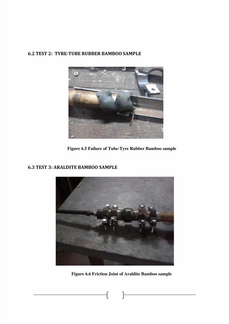
6.2 TEST 2: TYRE‐TUBE RUBBER BAMBOO SAMPLE
Figure 6.5 Failure of Tube-Tyre Rubber Bamboo sample
6.3 TEST 3: ARALDITE BAMBOO SAMPLE
Figure 6.6 Friction Joint of Araldite Bamboo sample

7/27/2019 Bamboo based cowshed
http://slidepdf.com/reader/full/bamboo-based-cowshed 37/47
28
Figure 6.7 Testing of Araldite Bamboo sample
Figure 6.8 Failure of Araldite Bamboo sample
Slip at joint

7/27/2019 Bamboo based cowshed
http://slidepdf.com/reader/full/bamboo-based-cowshed 38/47
29
6.4 TEST RESULTS
External diameter for all the samples = 35 mm
TABLE 6.1 Load taken by the test samples
S.No. Sample Load taken (kg)
1 Plain Bamboo Sample 800
2 Tube tyre on Bamboo Sample 1000
3 Araldite Bamboo Sample 1500
It can be concluded from the test results, the friction capacity of the bamboo increases with
various agents such as tube tyre rubber and araldite. The increase in the load taken is around 200
kg for tyre tube rubber with respect to plain bamboo sample. The increase in the load with use of
araldite is about 700 kg with respect to the plain bamboo sample.
After the previous tests, more tests have been carried out wherein the rubber coating was in
contact with bamboo with the help of araldite. The results of the tests are given in Table 4.2
(Shaw, 2012) . However, further tests need to be carried out to achieve accurate and reliable
results.
TABLE 6.2 Load taken by the new test samples
Test Number Load (Kg)
1 1600
2 1200

7/27/2019 Bamboo based cowshed
http://slidepdf.com/reader/full/bamboo-based-cowshed 39/47
30
Chapter 7 CONCLUSIONS AND RECOMMENDATIONS 7.1 CONCLUSIONS
This project has covered the analysis and the conceptual design of a typical bamboo based shed
structure under various loads and their combinations. Wind loads have been considered as per
IS 875 part 3 and the structure analyzed in a simple fashion, by considering the behavior of a
typical frame in the transverse direction. The roof is supported by bamboo pitched roof structure
and the columns are designed as battened bamboo members. The proposed structure aims to
provide an alternative environment friendly construction for a steel industrial shed. It can
serve multiple purposes, such as workshop for a cottage industry, warehouse, and other medium
industries. Not only is the structure light compared to conventional steel, it is at the same time
better and more economically viable than the arched roof structure and thus, several times
cheaper and eco friendly.
The design developed for the bamboo shed structure gives satisfactory results for the
computation of forces and cross-sections of all the components. The design of the various
components have been carried out in accordance with the IS codes and the experimental results.
Further, the manual analysis has been verified with analysis using STAAD Pro. Also, the
experimental tests for the friction capacity joints have been carried out for various bamboo
samples. From the results, it has been verified that the joints designed for the structure are safe
and feasible.
The culmination of the project has resulted in the complete design detail for the bamboo shedframe structure with detailed design of the foundation, base plate, columns, inclined and top
members and joints.
7/27/2019 Bamboo based cowshed
http://slidepdf.com/reader/full/bamboo-based-cowshed 40/47
31
7.2 RECOMMENDATIONS FOR FUTURE WORK
Some of the recommendations for future work in the project are as follows:1. The joints for the bamboo structure can be designed to be more strong and effective. New
design for stronger and lighter joints for connecting the pitched roof structure and the
columns of the bamboo shed structure can be designed.
2. The cost of construction of the bamboo frame has scope of reduction. With proper
substitute materials and further optimization of the design, it would result in decrease of the
cost for the structure. Also, as stated the improvement in the design of joints would lead to
a great decrease in the cost of the structure.
3. The construction of the whole bamboo shed should be carried out with the calculations and
design for the walls and the roof of the shed.
4. The design of the bamboo shed can be further optimized by calculating the most optimum
span length which results in the minimum forces due to wind load and dead load.
7.3 SOURCES OF ERROR
The calculations also involve some approximations which might lead to some error in
the computation of the forces and the critical sections. Some of these approximations are:
1. Since no standard codes of practice are available for bamboo, steel code (IS 800, 1984)
has been used wherever required, which might have lead to some error in the design.
2. While computing the force on the bamboo structure, the joints have been assumed to be
pin joints with negligible friction. This approximation might have lead to some error in
calculation of wind loads and moments.

7/27/2019 Bamboo based cowshed
http://slidepdf.com/reader/full/bamboo-based-cowshed 41/47
32
REFERENCES
1. Arya A.S. and Ajmani J.L., Design of Steel Structures, Nem Chand & Bros., (1992).
2. Bhalla S, Gupta S, Sudhakar P & Suresh R, Bamboo as Green alternative to Concrete and
Steel for modern structures, International Congress Of Environmental Research (ICER),
(2008).
3. Bhalla S., “Presentation on Foundations”, Department of Civil Engineering, IIT Delhi
4. CS Monitor, http://www.csmonitor.com/2008/0312/p14s01-stgn.html, (2008).
5. Ghavami, , K., Bamboo: Low cost and energy saving construction materials,
Proc. International Conference on Modern Bamboo Structures, 28-30 October,
Changsha, China, 5-21, (2007).
6. IS 875 Part 2, Code of practice for design loads for buildings and structures, imposed
loads, Bureau of Indian Standards , (1987).
7. IS 875 Part 3, Code of practice for design loads for buildings and structures, wind loads,
Bureau of Indian Standards, (1987).
8. IS 800, Code of practice for general construction in steel, Bureau of Indian Standards
(1984).
9. IS 800, Code of practice for general construction in steel, Bureau of Indian
Standards (2007).
10. IS 456 (2000), Plain and Reinforced Concrete- Code of Practice, Bureau of Indian
Standards, New Delhi
11. Korde, C. 2012, “Developing Bamboo Concrete as Structure Load Bearing Elements”, for
Rural Development & Technology, IIT Delhi12. Project Report on Shed Type Structures: Steel vs. Bamboo by Moti Baba, IIT Delhi, 2009.
13. Scientific American, http://www.sciam.com/article.cfm?id=cement-from-carbondioxide,
(2008).
14. Shaw A., Report on “Characterization of Engineered Bamboo for Buildings”, 2012.
15. Sinha S.N., Reinforced Concrete Design, Tata McGraw Hill, 2002.
16. Subramanian N., Design of Steel Structures, Oxford University Press, 2008.

7/27/2019 Bamboo based cowshed
http://slidepdf.com/reader/full/bamboo-based-cowshed 42/47
33
APPENDIX CALCULATIONS FOR BUILDING A
Total length 25m
Spacing 5m
Bay Width 6m
Height (max) 3+2=5m
Roof slope 18.5 degrees
Height above ground 3m
Velocity Vb = 47 m/s
k1 1 Class A structure
k2 1 Terrain category 2 structure
k3 1
Vz 47 m/s
Pz 1325.4 N/m2
Cpi 0.7 ‐0.7
External Pressure Coefiicients for h/w = 0.5 External Pressure Coefiicients for h/w = 0.5 & l/w= 4.17
Wind angle Wind angle
portion of roof 0 90 0 90
E 0 ‐0.7 A 0.7 ‐0.5
F 0 ‐0.6 B ‐0.25 ‐0.5
G ‐0.4 ‐0.7 C ‐0.6 0.7
H ‐0.4 ‐0.6 D ‐0.6 ‐0.1
CALCULATIONS FOR BUILDING B
Total length 25m
Spacing 5m
Bay Width 8m
Height (max) 3+2.5=5.5m
Roof slope 32 degrees
Height above ground 3m
Velocity Vb = 47 m/s

7/27/2019 Bamboo based cowshed
http://slidepdf.com/reader/full/bamboo-based-cowshed 43/47
34
k1 1 Class A structure
k2 1 Terrain category 2 structure
k3 1
Vz 47 m/s
Pz 1325.4 N/m2
Cpi 0.7 ‐0.7
External Pressure Coefiicients for h/w <= 0.5 Ext. Pressure Coeff for h/w <= 0.5 & l/w= 3.125
Wind angle Wind angle
portion of roof 0 90 0 90
E 0 ‐0.7 A 0.7 ‐0.5
F 0 ‐0.6 B ‐0.25 ‐0.5
G ‐0.4 ‐0.7 C ‐0.6 0.7
H ‐0.4 ‐0.6 D ‐0.6 ‐0.1
a roof1 roof2 b
Case 1 0 0.7 1.1 0.95
0 4.6375 7.2875 6.29375
Case 2 1.4 ‐0.7 ‐0.3 ‐0.45
9.275 ‐4.6375 ‐1.9875
‐
2.98125
Case 3 ‐1.2 ‐1.4 ‐1.4 ‐1.2
‐7.95 ‐9.275 ‐9.275 ‐7.95
Wind case
Column
1
Column
2 Tensile Moment Horizontal Tensile Moment Horizontal
Case 1 19.8 8.62 2.88 19.8 18.01 18.53
Wind normal, inside pressure
Case 2 ‐11.01 15.59 19.11 ‐11.01 1.81 ‐3.87
Wind normal, inside suction
Case 3 30.79 ‐8.49 ‐14.91 30.79 8.49 14.91
Wind along, inside pressure .
Case 4 0 1.49 2.48 0 ‐1.49 ‐2.48
Wind along, inside suction

7/27/2019 Bamboo based cowshed
http://slidepdf.com/reader/full/bamboo-based-cowshed 44/47
35
FORCES ON COLUMNS FOR BUILDING A & B
Wind case Column 1 Column 2
Tensile Moment Horizontal Tensile Moment Horizontal
6m 8m 6m 8m 6m 8m 6m 8m 6m 8m 6m 8m
Case 1 14.78 19.8 9.81 8.62 3.27 2.88 14.78 19.8 19.2 18 18.92 18.53
Wind normal,
inside
pressure
Case 2 ‐8.25 ‐11 16.67 15.59 19.47 19.1 ‐8.25 ‐11 2.89 1.81 ‐3.51 ‐3.87
Wind normal,
inside suction Case 3 23.09 30.8 ‐8.49 ‐8.49 ‐14.91 ‐14.9 23.09 30.8 8.49 8.49 14.91 14.91
Wind along,
inside
pressure .
Case 4 0 0 1.49 1.49 2.48 2.48 0 0 ‐1.49 ‐1.5 ‐2.48 ‐2.48
Wind along,
inside suction
CALCULATIONS FOR ALLOWABLE STRESS IN BAMBOO
COMPRESSIVE TENSILE
Yield stress,
fy 55 Mpa
15.7
1 S.F. = 3.5
Yield
stress, fy 120
Mp
a
34.2
9
S.F.
=
3.5
Elastic
Modulus 14 Gpa
Elastic
Modulus 14 Gpa
slenderness
ratio 80
slendernes
s ratio 80
fcc
21.5678
8 Mpa fcc
21.
6
Mp
a n 1.4 n 1.4
permissible
stress
11.0273
6 Mpa
permissible
stress 16
Mp
a
Bamboo with 40mm dia and 10mm wall thickness
Cross sectional
area=
94
2
mm
2
9E‐ m2
7/27/2019 Bamboo based cowshed
http://slidepdf.com/reader/full/bamboo-based-cowshed 45/47
36
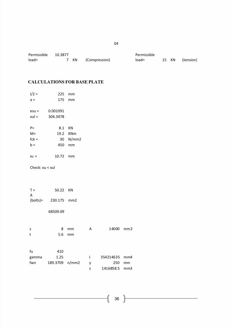
04
Permissible
load=
10.3877
7 KN (Compression)
Permissible
load= 15 KN (tension)
CALCULATIONS FOR BASE PLATE
l/2 = 225 mm
a = 175 mm
esu = 0.001091
xul = 304.3478
P= 8.1 KN
M= 19.2 KNm
fck = 30 N/mm2
b = 450 mm
xu = 10.72 mm
Check: xu < xul
T = 50.22 KN
A
(bolts)= 230.175 mm2
68509.09
s 8 mm A 14000 mm2t 5.6 mm
fu 410
gamma 1.25 I 354214635 mm4
fwn 189.3709 n/mm2 y 250 mm
z 1416858.5 mm3
7/27/2019 Bamboo based cowshed
http://slidepdf.com/reader/full/bamboo-based-cowshed 46/47
37
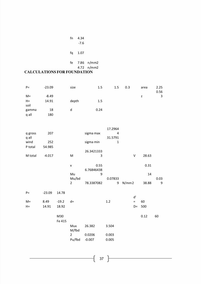
fn 4.34
‐7.6
fq 1.07
fe 7.86 n/mm2
4.72 n/mm2
CALCULATIONS FOR FOUNDATION
P= ‐23.09 size 1.5 1.5 0.3 area 2.25
M= ‐8.49 z
0.56
3
H= 14.91 depth 1.5
soil
gamma 18 d 0.24
q all 180
q gross 207 sigma max
17.2964
4
q all
wind 252 sigma min
31.5791
1
P total 54.985
M total ‐4.017 M
26.3421333
3 V 28.63
x 0.55 0.31
Mu
6.76846438
9 14
Mu/bd
2 78.3387082
0.07833
9 N/mm2 38.88
0.03
9
P= ‐23.09 14.78
M= 8.49 ‐19.2 d= 1.2
d'
= 60
H= 14.91 18.92 D= 500
M30 0.12 60
Fe 415
Mux 26.382 3.504
M/fbd
2 0.0206 0.003
Pu/fbd ‐0.007 0.005
7/27/2019 Bamboo based cowshed
http://slidepdf.com/reader/full/bamboo-based-cowshed 47/47
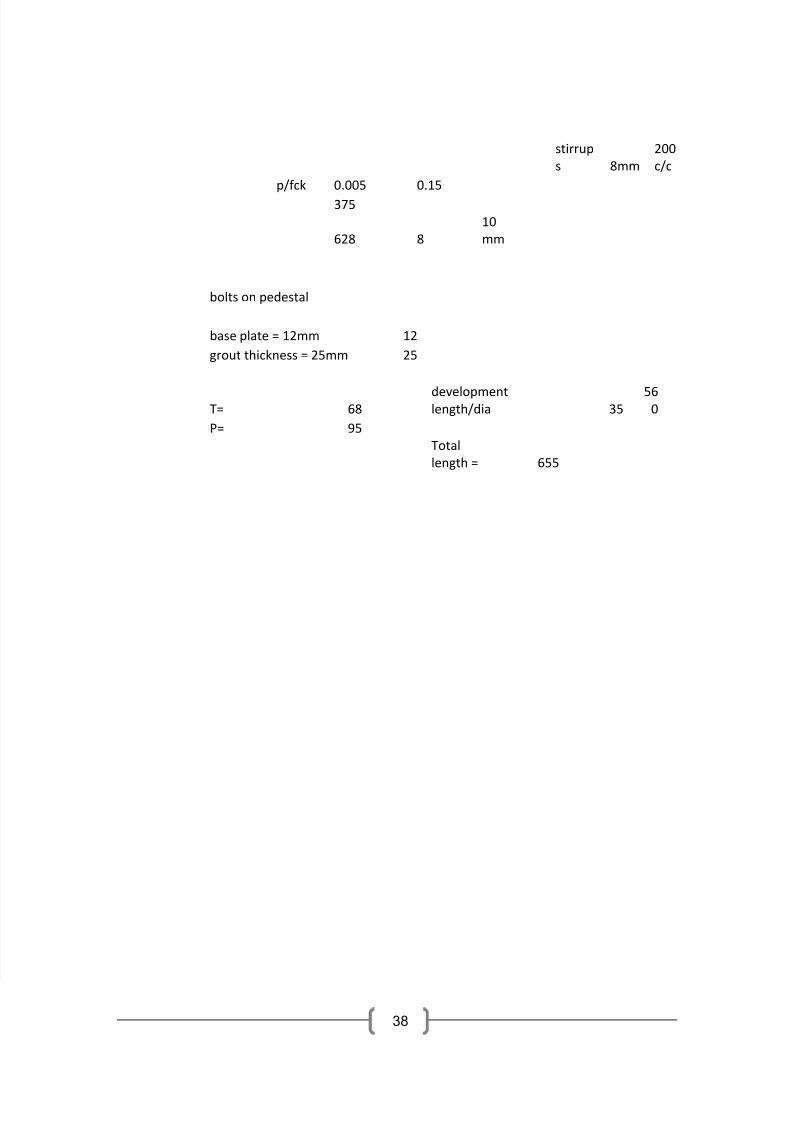
stirrup
s 8mm
200
c/c
p/fck 0.005 0.15
375
628 8
10
mm
bolts on pedestal
base plate = 12mm 12
grout thickness = 25mm 25
T= 68development length/dia 35
560
P= 95
Total
length = 655