ballscrew mount final report
TRANSCRIPT

University of Tennessee
Ball Screw Mount Design Mechanical Engineering Senior Design in conjunction with Accu-‐Router
William Brown, Patirck Connor, Corey Crumpton, Skye Jerrolds 12-‐12-‐2014

1
Abstract
A team of mechanical engineering seniors from the University of Tennessee have partnered with Accu-‐Router, an environment-‐friendly computer numerically controlled (CNC) refurbishing company, to redesign a ball screw mount. These mounts provide both the support structure and x-‐axis movement for several different CNC tables Accu-‐Router plans to refurbish. However, not only are these mounts costly, but also they require that the ball screw each mount supports be machined and threaded as well – further adding to both the overall cost and availability of these two parts. As a company that values timely service and competitive prices, it is of great importance that the team can produce new mounts that will be in accordance with Accu-‐Router’s standards.
The intent of this report is to present the research, redesign, and viability of the new and improved ball screw mount. In this report, the background of the project is discussed in more detail, design specifications for current mounts are explained, several different designs are presented, and a final design is selected as the prototype. For the final design, a finite element analysis is performed through Solidworks, a prototype is assembled and tested during the spring semester, and the acquired data is analyzed and documented.
This team believes that through the efforts outlined in this report, a superior mount design will successfully be implemented into Accu-‐Router’s line of CNC machines.

2
Table of Contents Abstract ....................................................................................................................................................... 1
Background of Problem ............................................................................................................................... 3
Work Statement .......................................................................................................................................... 3
Design Specifications ................................................................................................................................... 4
Design Concepts .......................................................................................................................................... 5
Design A ................................................................................................................................................... 5
Design B ................................................................................................................................................... 8
Design C ................................................................................................................................................. 10
Evaluation of Concepts .............................................................................................................................. 13
Scoring Process ...................................................................................................................................... 14
Recommendation .................................................................................................................................. 14
Sponsor Feedback .................................................................................................................................. 15
Finite Element Analysis .............................................................................................................................. 15
Fabrication of Prototype ............................................................................................................................ 18
Economic Impact ....................................................................................................................................... 22
Conclusion and Recommendations ........................................................................................................... 22
Appendix .................................................................................................................................................... 24
Gantt Chart ............................................................................................................................................ 24
September-‐December ............................................................................................................................ 24
January-‐April .......................................................................................................................................... 26
January .................................................................................................................................................. 26
February ................................................................................................................................................. 27
March .................................................................................................................................................... 27
April ....................................................................................................................................................... 28
Engineering Calculations ........................................................................................................................ 29
Detailed Shop Drawings ......................................................................................................................... 30

3
Background of Problem Accu-‐Router is a small business that specializes in “green engineering,” specifically for CNC, or computer numerically controlled, machines. They buy used CNC routers and refurbish them with added improvements to increase the longevity of the machine. Additionally, the company also builds these CNC machines from the ground up. Due to their interest in reusing materials, it would be beneficial to lower costs in as many areas as possible. One area of high cost is the expense of having both the ball screw mounts and the corresponding ball screws machined. The overall cost of the mount, $494.49, is due to the labor involved with machining very tight tolerances for the bore of the ball screw. The cost is further increased because the ends of the ball screw must be machined not only to match the inside diameter of the mount, but also to include threads that will secure the ball screw through the mount with a lock nut on the outside. Additionally, having the ball screw machined and threaded adds a significant lead time to the availability of this part. This down time is of great concern to Accu-‐Router, and having a ball screw that requires no machining would be highly beneficial.
Work Statement The University of Tennessee’s senior design group is dedicated to redesigning and producing a prototype for an x-‐axis ball screw mount for Accu-‐Router. Through the team’s design process and engineering analysis, a mount will be produced that retains both the integrity of the original design as well as a reduced price for an overall superior product. The main focus of this project is to take an existing component of the CNC machine and redesign it to produce a more cost effective product. This redesign process integrates previous mounting specifications, maintains the structural integrity of the original component, and accounts for material and labor costs of producing a new component. The team’s preliminary design is the result of not only eliminating unnecessary material associated with the component, but also complying with mounting specification requirements in order to implement the new product into existing CNC tables. Finally, the team will report the results of its finite element analysis and prototype testing to Accu-‐Router in a timely manner in order to obtain feedback and create a functional component that meets their standards.

4
Design Specifications In order to maximize the functionality of the design, the new prototype needs to satisfy the following criteria depicted in Figure 1.
Figure 1: Bolt-‐Hole Pattern Of Original Mount
The base of the design must maintain the exact dimensions of the original design, 5.25 inches long, 4 inches wide, and 1 inch high, and also must contain the four original bolt-‐holes’ pattern. The location of these bolt-‐hole centroids, measured from the bottom left corner of the base, are as follows: 0.5 inches by 0.625 inches, 0.5 inches by 3.375 inches, 4.75 inches by .625 inches, and 4.75 inches by 3.375 inches. The diameter of all the bolt-‐holes must be 0.41 inches. The height of the ball screw mount and its centroid, measured from the base, are 5 inches and 3.75 inches respectively. The centroid of the mount must be placed 2.625 inches from the left and right side of the base. Finally, the new design must also have an overall lower cost than the original design. This can be done by implementing both a creative alternative to not only machining and threading the ball screw mount, but also by fastening the ball screw with a large lock nut. The new design must also be able to withstand the required load as well as not produce any axial, lateral, or rotational loading on the ball screw.
5
Design Concepts Design A Features The team’s first design (Design A) is a very simple design requiring only two pieces to be machined. Its simplicity also allows it to be very easily produced, resulting in a reduction of the cost of production.
This design uses a two-‐screw clamping system and a setscrew to keep the ball screw in place. The most important feature of this design is that by increasing the ball screw mount bore, there is no longer a need to machine down and thread the end of the ball screw to secure it in the mount. It accomplishes this while also meeting all of the requirements set forth by Accu-‐Router, including retaining all original bolt hole patterns, meeting the height requirement of 5 inches, and retaining the height of the ball screw bore’s centroid of 3.75 inches.
Additional new features of Design A are listed below.
-‐ Removal of the gussets (triangular steel pieces) that were welded on to the side of the original design. The team concluded that these gussets not only served little purpose, but also added extra cost to production.
-‐ Increase in the size of the ball screw bore to 1.97 inches (50 mm). This will allow the ball screw to fit into the mount with no machining. This will cut down on the amount of machining and the overall cost.
-‐ Decrease in overall volume. This was achieved by shortening the length of the neck. The team determined this would cut down on material cost.
-‐ Increased width of the base of the neck to accommodate the larger ball screw bore. -‐ Changed the position of the clamping system. This was done to meet the 5-‐inch height
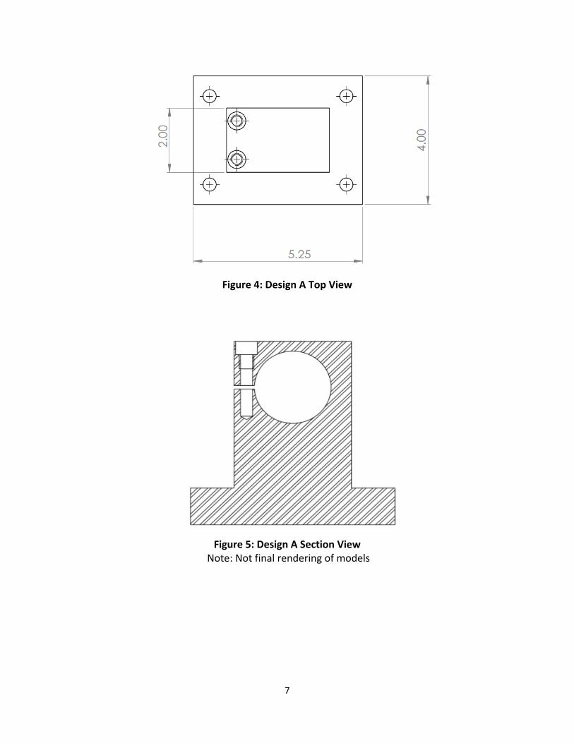
requirement. The team removed the screws from the top of the ball screw bore and instead placed them vertically, perpendicular to the base, and next to the ball screw bore (Figure 5). They lay flush with the topside of the mount due to a counter bore.
Benefits Design A is a very simple design that is similar to the original mount. One of the benefits of such a simple design is that it will require a minimal amount of machining to complete the part, thus cutting down on overall cost. This design also cuts cost since the addition of the setscrew allows the ball screw to be clamped into the mount without any machining or threading. Design A is a practical solution to the problem set forth by Accu-‐Router as it cuts down on price while still meeting the standards and requirements expected.
Feasibility Design A has a very high feasibility because it is a simple design; it meets all the requirements and functions as specified by Accu-‐Router, and it is similar to the original design. All of the features and benefits specified above will help reduce costs and make this design a very practical option for replacing Accu-‐Router’s current ball screw mount.

6
Figure 2: Design A Isometric View
Figure 3: Design A Front View
7
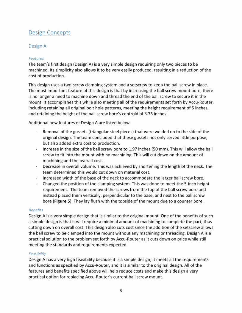
Figure 4: Design A Top View
Figure 5: Design A Section View
Note: Not final rendering of models
8
Design B
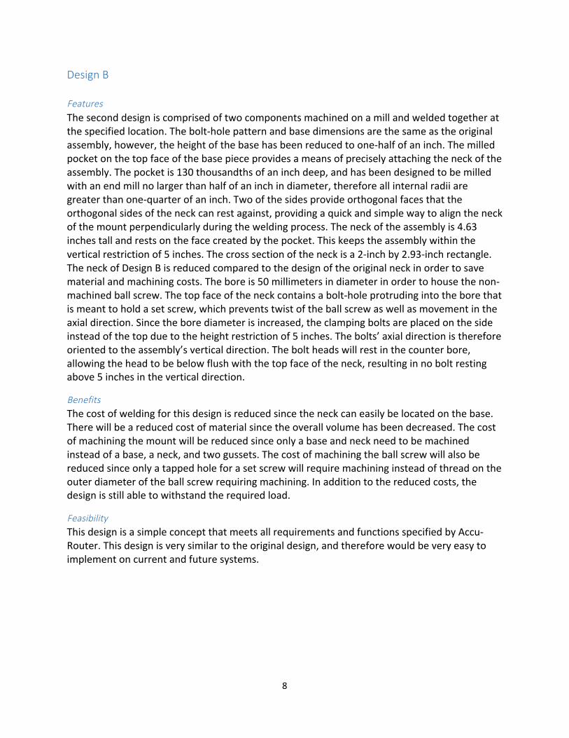
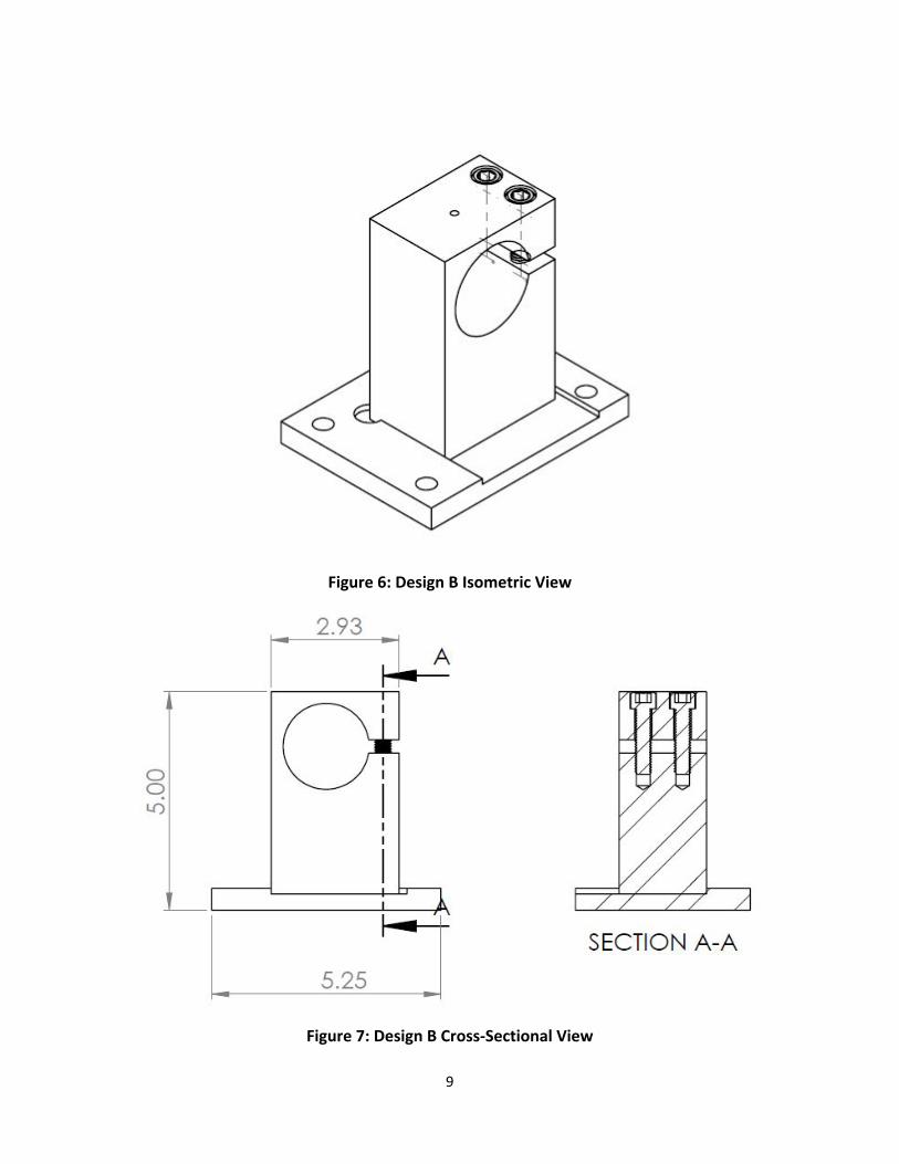
Features The second design is comprised of two components machined on a mill and welded together at the specified location. The bolt-‐hole pattern and base dimensions are the same as the original assembly, however, the height of the base has been reduced to one-‐half of an inch. The milled pocket on the top face of the base piece provides a means of precisely attaching the neck of the assembly. The pocket is 130 thousandths of an inch deep, and has been designed to be milled with an end mill no larger than half of an inch in diameter, therefore all internal radii are greater than one-‐quarter of an inch. Two of the sides provide orthogonal faces that the orthogonal sides of the neck can rest against, providing a quick and simple way to align the neck of the mount perpendicularly during the welding process. The neck of the assembly is 4.63 inches tall and rests on the face created by the pocket. This keeps the assembly within the vertical restriction of 5 inches. The cross section of the neck is a 2-‐inch by 2.93-‐inch rectangle. The neck of Design B is reduced compared to the design of the original neck in order to save material and machining costs. The bore is 50 millimeters in diameter in order to house the non-‐machined ball screw. The top face of the neck contains a bolt-‐hole protruding into the bore that is meant to hold a set screw, which prevents twist of the ball screw as well as movement in the axial direction. Since the bore diameter is increased, the clamping bolts are placed on the side instead of the top due to the height restriction of 5 inches. The bolts’ axial direction is therefore oriented to the assembly’s vertical direction. The bolt heads will rest in the counter bore, allowing the head to be below flush with the top face of the neck, resulting in no bolt resting above 5 inches in the vertical direction.
Benefits The cost of welding for this design is reduced since the neck can easily be located on the base. There will be a reduced cost of material since the overall volume has been decreased. The cost of machining the mount will be reduced since only a base and neck need to be machined instead of a base, a neck, and two gussets. The cost of machining the ball screw will also be reduced since only a tapped hole for a set screw will require machining instead of thread on the outer diameter of the ball screw requiring machining. In addition to the reduced costs, the design is still able to withstand the required load.
Feasibility This design is a simple concept that meets all requirements and functions specified by Accu-‐Router. This design is very similar to the original design, and therefore would be very easy to implement on current and future systems.
9
Figure 6: Design B Isometric View
Figure 7: Design B Cross-‐Sectional View

10
Design C
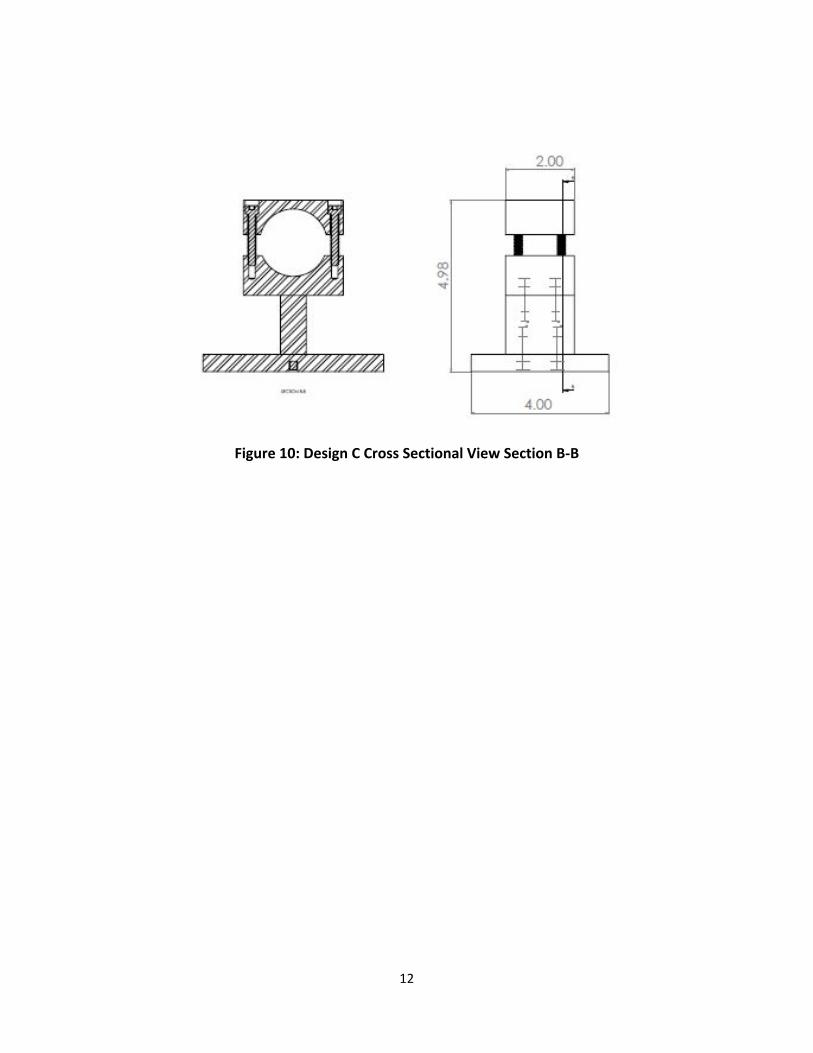
Features The third design is comprised of four components that are machined and bolted together at the specified locations. The bolt-‐hole pattern and base dimensions are the same as the original assembly, however, the height of the base has been reduced to one-‐half of an inch. The neck of the assembly is 1.72 inches tall and rests symmetrically on the top face of the base. The cross section of the neck is a 0.75-‐inch by 2-‐inch rectangle. The neck of Design C is reduced compared to the design of the original neck in order to save material and machining costs. The neck attaches to the base via two bolts that are run from the bottom of the base. The neck supports the bottom of the clamping head. The clamping head is attached to the neck via two bolts that are run from the top of the bottom clamping head. The clamping head contains a cylindrical extruded cut that is used to house and center the ball screw. The bore will be increased to 50 millimeters in diameter in order to house the non-‐machined ball screw. The top clamping head is attached to the bottom clamping head via four bolts on the four corners of the clamping heads. The two heads do not come into contact, and instead has a cylindrical bore that houses the ball screw. The bolts then provide the clamping force that the clamping heads produce on the ball screw. The top face of the clamping head contains a bolt-‐hole protruding into the bore that is meant to hold a set screw, which will prevent twist of the ball screw as well as movement in the axial direction. The bottom clamping head’s dimensions are 2.9 inches long, 2 inches wide, and 1.15 inches high with the exception of the bore and bolt holes. The top clamping head’s dimensions are 2.9 inches long, 2 inches wide, and 1 inch high with the exception of the bore and bolt holes.
Benefits This design eliminates the cost of welding since the components are now attached via bolts. The cost of material is reduced since the overall volume has been decreased. The cost of machining the ball screw is also reduced. Only a tapped hole for a set screw will need to be machined instead of thread on the outer diameter of the ball screw. In addition to the reduced costs, the design is still able to withstand the required load.
Feasibility This design is a relatively simple concept that meets all requirements and functions specified by Accu–Router. In order to implement the design, the user would simply apply a thread-‐locker to the bolts as they are placed in the appropriate locations. The mount is then placed in the appropriate location as the ball screw is located and mounted.

11
Figure 8: Design C Isometric View
Figure 9: Design C Cross Sectional View Section A-‐A
12
Figure 10: Design C Cross Sectional View Section B-‐B

13
Evaluation of Concepts In order to determine the team’s ideal design, a Pugh chart was created that evaluates the benefits and drawbacks of the three designs. The two main criteria of the Pugh chart are cost and safety, and each criterion is given 50% total weight. Figure 11 shows the details of the Pugh chart.
Priority
Design A Design B Design C
0.5 Safety 0.1 Load Capacity 3 3 2
0.4 Torque Resistance 3 3 2
0.5 Cost 0.2 Welding 1 2 3
0.1 Machining 2 2 1
0.1 Assembly 2 3 2
0.1 Material 1 1 3
Total 2.2 2.5 2.2
*Total = priority*ranking *Rankings on 1-‐3 scale
Figure 11: Matrix Decision Pugh Chart
Within the safety category, the two subcategories were load capacity and torque resistance. Torque resistance was given 40% weight due to the continuous rotational forces the motor applies to the ball screw while it is in use. The load capacity was given 10% weight since the ball screw only experiences minimal axial forces that are transmitted to the mounts. Within the cost category, the four subcategories were welding, machining, assembly, and material. Machining was given 20% weight due to the major considerations of machining both the mounts and the ball screw. A design that could successfully accommodate a non-‐machined ball screw would decrease cost and availability time significantly; therefore this category was weighted with more importance compared to the other cost categories. Although the labor costs for welding are generally higher than machining, each design concept requires no more welding than the original design, and thus welding was only given 10% weight. Assembly was given 10% weight as well to account for the differences between the assembly of the original design, Design A, Design B, and Design C. Finally, material costs were also given 10% weight because the team intends to use the same material as the current mounts.
14
Scoring Process The scoring process took each design and rated all of the categories on a 1 to 3 scale, where 1 represents a poor performance and 3 represents an excellent performance. Each score given was an estimate based on the knowledge that the team has of both general machine design and the original design. The rest of this section will highlight the strengths and weaknesses of each design. Design A was scored a 3 in each safety category since Design A varied only slightly from the original design, and the original design had an exceptional safety performance. In the cost section, Design A scored a 2 in the machining and assembly categories since the gussets are removed from the original design. Finally, Design A scored a 1 in the welding and material categories. Although the welding and material requirements for Design A were less than the original design, they required significantly more welding and material than the other design concepts. Similar to Design A, Design B scored a 3 in each safety category since Design B also closely resembles the original design. In the cost section, Design B scored a 3 in assembly because it only requires the attachment of the base plate to the mount itself. However, this design scored a 2 in machining and welding since it requires a great deal of machining for the milled cutout so both the alignment of the mount and welding of the mount into the cutout. Finally, Design B scored a 1 in material because, similar to Design A, it requires more material than design C. Finally, Design C scored a 2 in each safety category due to the unique design’s unknown reliability, caused from its slender neck not being able to withstand the rotational forces applied to the mount. In the cost section, Design C scored a 3 in material and welding since it requires very little material as well as no welding. This design scored a 2 in assembly since the user is required to assemble the entire mount. Finally, this design scored a 1 in machining since each component requires individual machining, thus increasing the cost of the mount. Recommendation Originally, the team recommended Design B since its overall score on the Pugh chart was a 2.5, while the other designs each scored a 2.2. Based on the assumption that Design B was similar to the original design, the team was confident it would not only be reliable, but also reduce costs due to the simplicity of accurately aligning the neck onto the base via the milled cutout. However, in case Design B was not sufficient, the team decided that Design A would be the next best option, despite that both Design A and Design C scored a 2.2 on the Pugh chart. The justification behind this decision was that Design A was closer to the original design than Design C, and therefore would have less safety risks.

15
Sponsor Feedback Although Design B was recommended to Accu-‐Router, they informed the team that there is a high risk of the steel distorting when being welded into a milled piece. Therefore, they decided that Design A would be the best choice among the three designs. Based on the decision matrix and scoring process, the team supported their decision. Since Design A is similar to the original design, it would create the least amount of unknown variables when the part is tested.
Finite Element Analysis
The team decided to do a finite element analysis (FEA) to determine the maximum stresses and the factor of safety of the ball screw mount. To do the FEA, the decision was made to create a model assembly of the ball screw mount, the ball screw, and the setscrew within Solidworks. The team ran into difficulties replicating the ball screw and setscrew, so the decision was made to model them as cylinders. The simulated ball screw was a cylinder with a diameter of 50 millimeters and a length of 12 inches. The simulated setscrew was a cylinder modeled after an 8-‐32 and 5/16 inch set screw. However, the team later learned that the 8-‐32 set screw had problems breaking after use, and therefore was changed to a ¼-‐20 sized screw instead. After assembling these models, the simulation program in Solidworks was used to run the analysis.
During the simulation program, a torque and an axial force was applied on the ball screw (see Figure 12). The torque was found using the motor specs that were acquired from Accu-‐Router. The axial force was found using the maximum speed of the table, the time it takes to reach the maximum speed, and the weight of the table. The torque applied was 70 N-‐m (51.6 ft-‐lb), and the axial force applied was 414 lbs. To simulate the mount being bolted on to the machine, the bottom face of the mount was fixed. In an iterative process, the team simulated tightening the bolts down and deforming the top face of the mount by up to 2mm.
Figure 12: FEA Model Assembly

16
Once all of the forces were applied, a mesh was created of the assembly and the simulation was performed. Several variables attained from the analysis include the maximum stresses, the location of the maximum stresses (see Figure 13), and the factor of safety (see Figure 14). All of these values are located on Table 1. The team was also interested in finding out if the setscrew would be able to withstand the shear and axial forces applied, as well as determining what type and size of weld would be appropriate to use.
Figure 13: FEA Stress Diagram
Figure 14: FEA Factor of Safety Diagram
17
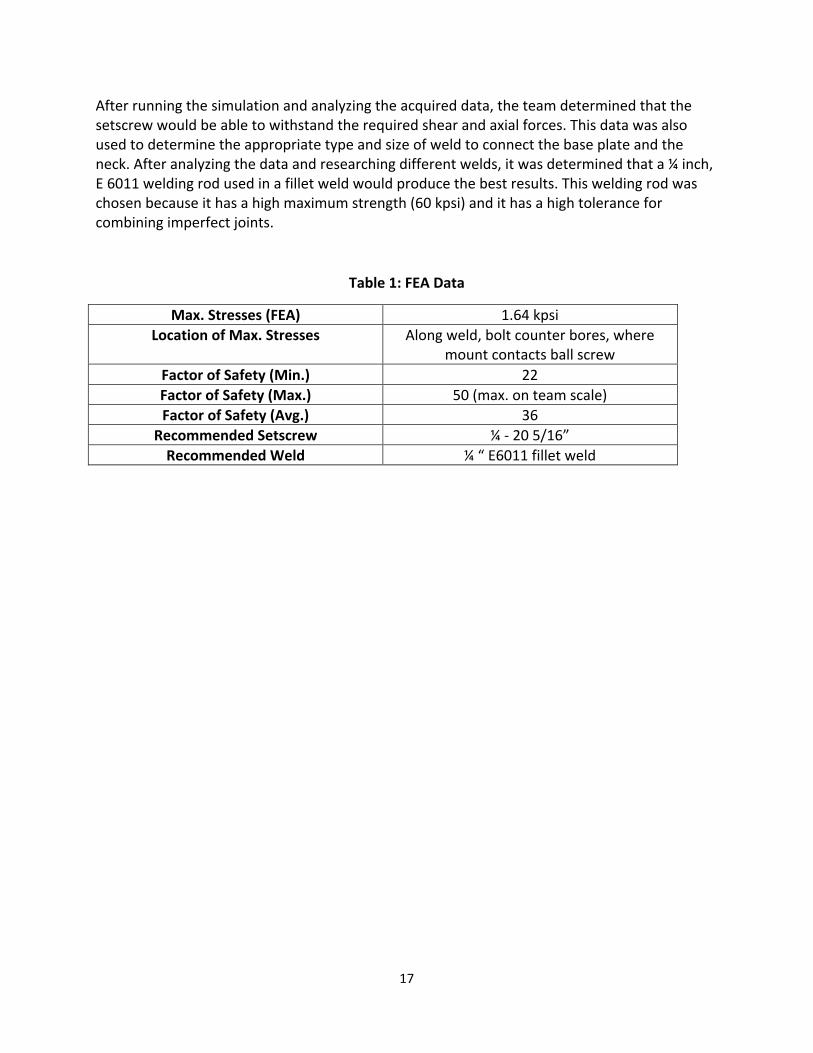
After running the simulation and analyzing the acquired data, the team determined that the setscrew would be able to withstand the required shear and axial forces. This data was also used to determine the appropriate type and size of weld to connect the base plate and the neck. After analyzing the data and researching different welds, it was determined that a ¼ inch, E 6011 welding rod used in a fillet weld would produce the best results. This welding rod was chosen because it has a high maximum strength (60 kpsi) and it has a high tolerance for combining imperfect joints.
Table 1: FEA Data
Max. Stresses (FEA) 1.64 kpsi Location of Max. Stresses Along weld, bolt counter bores, where
mount contacts ball screw Factor of Safety (Min.) 22 Factor of Safety (Max.) 50 (max. on team scale) Factor of Safety (Avg.) 36
Recommended Setscrew ¼ -‐ 20 5/16” Recommended Weld ¼ “ E6011 fillet weld

18
Fabrication of Prototype
Before the first prototypes were produced, a few changes were made to the mounts within Solidworks. After the small modifications were completed, Accu-‐Router was contacted and the final detailed shop drawings were sent. Accu-‐Router officially put in the work order for the mount at the end of December. Once the prototype was delivered a few tests were developed to run on the mounts. These tests were developed to see if the requirements set by Accu-‐Router were met. The requirements included: the ball screw must fit in the mount, the ball screw must not twist in the mount, and the ball screw must not push or pull within the mount.
Fig. 15 Prototype
Special Considerations, Issues in Building Prototype
The original plan was to tap the ball screw to allow the setscrew, located on top of the mount, to screw in to the ball screw ensuring no twist within the mount occurred. When the team approached the machine shop to tap the ball screw, it was brought to the team’s attention that unless the mount and the ball screw were tapped at the same time, the threads would not match up. The solution was to drill a hole in the ball screw with a diameter of (0.25 in.), which is the major diameter of the setscrew, see Fig. 16, in order to use the set screw as a pin.

19
Fig. 16 End of Ball screw with hole
Design of Test Apparatus and Test Procedure
Before the prototype was tested on a machine, a simple test was designed to ensure that the mount met the requirements set forth by Accu-‐Router, which were: the mount must house the ball screw, the ball screw must not twist within the mount, and the ball screw must not move axially within the mount.
The team was given some values for external forces that would be applied to the ball screw, including a 70 N*m torque, and a 1400 N axial force. In order to apply the torque on the ball screw, a hexagonal nut was welded to the end of the ball screw, see Fig. 17. This was done so that the team could take a wrench and apply a torque to the ball screw. To simulate the conditions the mount would most likely see when placed on an operating machine, the test needed to fix the base of the mount, insert the ball screw, and apply our external forces.
Fig. 17 Welded Nut

20
For the first test, the base of the ball screw was fixed to a workbench using 3 medium sized C-‐clamps. A two-‐foot section of the ball screw was then inserted into the mount. To secure the ball screw within the mount, two clamping bolts and a setscrew were inserted and tightened. Once the forces were applied, it was determined if any twisting, or pushing/ pulling occurred within the mount. To apply the loads, a wrench was used that was approximately a foot long. The wrench was oriented as close to horizontal as possible in order to ensure the greatest amount of torque, and then a weight of 160 pounds was hung from the end. This resulted in a moment slightly more than three times the given value of 70 N*m.
Fig. 18 Simple Test in Estabrook
After the simple test was completed, the team traveled to the Accu-‐Router plant in Morrison, TN. The purpose of this visit was to test the mounts on the machines that the mounts would be used on. Once the mounts were bolted onto the CNC machine, a full-‐length ball screw was inserted and supported solely by the newly designed mounts. The clamping bolts were inserted and tightened, and it was decided that the first test would be completed without the use of the setscrew. If needed, a second test would be run with a set screw inserted. An accelerometer was also placed on the table to get a more accurate value for the axial force applied to the ball screw.

21
Fig. 19 Accu-‐Router Test 1&2
Fig. 20 Accu-‐Router Test 3
Test Results
Preliminary Testing This test involved tightening the clamping screws, as well as inserting the setscrew. After applying approximately three times the given load of 70 N*m torque to the end of the ball screw, there was no visible twisting or axial movement within the mount.
Real World Testing This test involved bolting the prototype mounts to the machines in which they would be used on. For this test we only tightened the clamping bolts and did not include the setscrew. After the machine was run, there was no twisting, pushing, or pulling of the ball screw within the
22
mount. The data recorded by the accelerometer provided an acceleration of the table of 36.702 ft/s. Using the acceleration data, along with the weight of the table (1200 lb or 37.267 slugs), the axial force was calculated at 1367.77 lbf. This is greater than the predicted axial force due to the fact that Accu-‐Router uses a bell shaped curve to model the acceleration rate. This curve was unavailable to the team previous to the site testing, and therefore constant acceleration had to be assumed.
The tests ran on the prototypes show that the new mounts can withstand the maximum loads without allowing any movement of the ball screw. It was also found that the mounts secure the ball screw with or with out the setscrew inserted. The tests also showed that the ball screw could be secured without having to machine the ends down. Ultimately, the testing showed that meet all requirements set forth by Accu-‐Router.
Economic Impact
Since the main objective of this design was to decrease the overall costs associated with the mount, economic impact played a significant role in designing of the model. Two ways the overall cost was decreased was by removing the gussets off the side of the mount as well as increasing the bore diameter in order to reduce the machining cost of the ball screw. The result is a price reduction of 375 dollars. Excluding the additional costs of turning the ball screw, the original mount’s quote is 495 dollars. The newly designed mount’s quote is 120 dollars. This quote also excludes the cost of machining the ball screw, however immensely less machining is involved; therefore, there will be a significant price reduction associated with the ball screw as well. Since the new design decreases the cost by a factor of 4.125 (or a price reduction of 75.8%), the design has an undisputable positive impact.
Conclusion and Recommendations
The objective of this design project was to design a cheaper mount for a CNC ball screw that still withstands the maximum loads on the ball screw without allowing the ball screw to rotate or move axially. This was achieved via computer animated design software, finite element analysis software, and the fabrication of a prototype to ensure the design works. The results of the finite element analysis show that the model withstands the maximum axial and torsional loads. The test of the prototype also showed that the model withstands the maximum loads without allowing rotation or axial movement. In addition to withstanding the maximum loads, the model is also cheaper than the original design. This is due to the decreased machining costs

23
of the components involved as well as significantly less machining to the ball screw itself. The result is a cheaper, yet functional model.
During the prototype testing, the ball screw was mounted on two of the designed mounts. Neither side of the ball screw had a setscrew in place. Based on this lack of a set screw as well as the results in the testing, the design team from the University of Tennessee observes that a set screw is not needed, which would further decrease the cost of the mount and screw assembly. However the team recommends the use of this set screw. While both ends do not need one, the assembly is more reliable and can withstand more loads over time with the setscrew in place.

24
Appendix
Gantt Chart September-‐December
September
Task Start Date
End Date
# of
Days 16-‐Sep
17-‐Sep
18-‐Sep
19-‐Sep
20-‐Sep
21-‐Sep
22-‐Sep
23-‐Sep
24-‐Sep
25-‐Sep
26-‐Sep
27-‐Sep
28-‐Sep
29-‐Sep
30-‐Sep
Func. and Req. Docu-‐ment
9/16/14 9/23/14 8
Design Con-‐cepts
9/23/14 9/25/14 3
Pugh Chart 9/25/14 9/30/14 6
During the month of September, the team focused on planning the initial design ideas and evaluated the pros and cons of each design by creating a Pugh Chart. A functions and requirements document was also prepared that details the specifications for each design. October
Task Start Date
End Date
# of
Days 1-‐ Oct
2-‐Oct
3-‐Oct
4-‐Oct
5-‐Oct
6-‐Oct
7-‐Oct
8-‐Oct
9-‐Oct
10-‐Oct
11-‐Oct
12-‐Oct
13-‐Oct
14-‐Oct
15-‐Oct
16-‐Oct
Pugh Chart 10/1/14 10/7/14 7
1st
Design Review
10/7/14 10/7/14 1
Final Design Decision
10/7/14 10/21/14 15
3-‐D Model 10/21/14 10/31/14 11
Assembly Drawing 10/21/14 10/31/14 11
Design of
Subsystems 10/21/14 10/31/14 11

25
Task Start Date End Date
# of
Days 17-‐Oct
18-‐Oct
19-‐Oct
20-‐Oct
21-‐Oct
22-‐Oct
23-‐Oct
24-‐Oct
25-‐Oct
26-‐Oct
27-‐Oct
28-‐Oct
29-‐Oct
30-‐Oct
31-‐Oct
Pugh Chart
10/1/14 10/7/14 7
1st Design Review
10/7/14 10/7/14 1
Final Design Decision
10/7/14 10/21/14 15
3-‐D
Model 10/21/14 10/31/1
4 11
Assembly Drawing 10/21/14
10/31/14 11
Design of
Subsystems 10/21/14
10/31/14 11
During the month of October, the team presented each of the three designs to Accu-‐Router, and a mutual decision to pursue Design A was reached after evaluating the pros and cons of each design. After the final design was determined, a 3D model and an assembly drawing of the new design were created in Solidworks. November
Task Start Date
End Date
# of
Days 1-‐ Nov
2-‐Nov
3-‐Nov
4-‐Nov
5-‐Nov
6-‐Nov
7-‐Nov
8-‐Nov
9-‐Nov
10-‐Nov
11-‐Nov
12-‐Nov
13-‐Nov
14-‐Nov
15-‐Nov
3-‐D Model
11/1/14 11/15/14 15
Assembly Drawing 11/1/14 11/15/14 15
Design of Sub-‐
systems
11/1/14 11/15/14 15
2nd
Design Review
11/7/14 11/20/14 14
Design Report 11/1/14 11/31/14 31
Task Start Date
End Date
# of
Days 16-‐Nov
17-‐Nov
18-‐Nov
19-‐Nov
20-‐Nov
21-‐Nov
22-‐Nov
23-‐Nov
24-‐Nov
25-‐Nov
26-‐Nov
27-‐Nov
28-‐Nov
29-‐Nov
30-‐Nov
3-‐D Model 11/1/14 11/15/14 16
Assembly Drawing 11/1/14 11/15/14 16
Design of Sub-‐
systems
11/1/14 11/15/14 16
2nd Design Review
11/7/14 11/20/14 14
Design Report 11/1/14 11/31/14 31

26
During the month of November, the team continued to work on the 3D model and assembly drawing of the new design. An FEA analysis was completed in Solidworks to determine if the new part could bear both the required load and torque while maintaining a high safety factor. Once this was completed, the team prepared to present the acquired data to Accu-‐Router for the second design presentation at the beginning of December. December
Task Start Date End Date # of Days 1-‐Dec 2-‐Dec 3-‐Dec 4-‐Dec 5-‐Dec 6-‐Dec 7-‐Dec 8-‐Dec 9-‐Dec 10-‐Dec 11-‐Dec
2nd Design Presentation 12/3/14 12/3/14 1
First Prototype 12/1/14 12/3/14 3
Spring Gant Chart 12/1/14 12/11/14 11
During the month of December, the team presented the acquired data to Accu-‐Router to show that the new design would be both reliable and cost efficient. Plans for next semester’s work were laid out, and a completed final report on the team’s progress during this semester was submitted.
January-‐April
January Task Start Date
End Date
# of Days 7-‐Jan 8-‐Jan 9-‐Jan 10-‐Jan 11-‐Jan 12-‐Jan 13-‐Jan 14-‐Jan 15-‐Jan 16-‐Jan 17-‐Jan 18-‐Jan
Adjust Part to be Re-‐
manufactured (If Needed)
1/7/15 1/21/15 15
Manufacturing of Ball Screw
Mount by Accu-‐Router*
1/7/15 2/21/15 46
Task Start Date
End Date
# of Days 19-‐Jan 20-‐Jan 21-‐Jan 22-‐Jan 23-‐Jan 24-‐Jan 25-‐Jan 26-‐Jan 27-‐Jan 28-‐Jan 29-‐Jan 30-‐Jan
Adjust Part to be Re-‐
manufactured (If Needed)
1/7/15 1/21/15 15
Manufacturing of Ball Screw
Mount by Accu-‐Router*
1/7/15 2/21/15 46
27
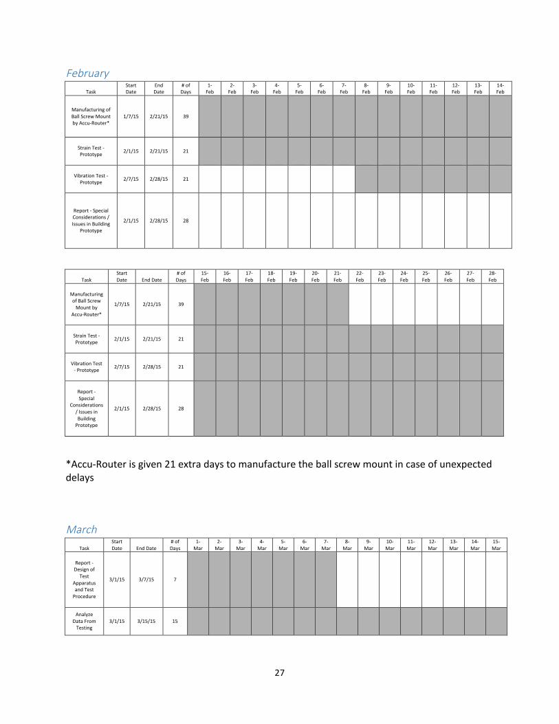
February Task
Start Date
End Date
# of Days
1-‐Feb
2-‐Feb
3-‐Feb
4-‐Feb
5-‐Feb
6-‐Feb
7-‐Feb
8-‐Feb
9-‐Feb
10-‐Feb
11-‐Feb
12-‐Feb
13-‐Feb
14-‐Feb
Manufacturing of Ball Screw Mount by Accu-‐Router*
1/7/15 2/21/15 39
Strain Test -‐ Prototype 2/1/15 2/21/15 21
Vibration Test -‐ Prototype 2/7/15 2/28/15 21
Report -‐ Special Considerations / Issues in Building
Prototype
2/1/15 2/28/15 28
Task Start Date End Date
# of Days
15-‐Feb
16-‐Feb
17-‐Feb
18-‐Feb
19-‐Feb
20-‐Feb
21-‐Feb
22-‐Feb
23-‐Feb
24-‐Feb
25-‐Feb
26-‐Feb
27-‐Feb
28-‐Feb
Manufacturing of Ball Screw Mount by
Accu-‐Router*
1/7/15 2/21/15 39
Strain Test -‐ Prototype 2/1/15 2/21/15 21
Vibration Test -‐ Prototype 2/7/15 2/28/15 21
Report -‐ Special
Considerations / Issues in Building Prototype
2/1/15 2/28/15 28
*Accu-‐Router is given 21 extra days to manufacture the ball screw mount in case of unexpected delays March
Task Start Date End Date
# of Days
1-‐Mar
2-‐Mar
3-‐Mar
4-‐Mar
5-‐Mar
6-‐Mar
7-‐Mar
8-‐Mar
9-‐Mar
10-‐Mar
11-‐Mar
12-‐Mar
13-‐Mar
14-‐Mar
15-‐Mar
Report -‐ Design of
Test Apparatus and Test Procedure
3/1/15 3/7/15 7
Analyze Data From Testing
3/1/15 3/15/15 15

28
Task Start Date
End Date
# of Days
16-‐Mar
17-‐Mar
18-‐Mar
19-‐Mar
20-‐Mar
21-‐Mar
22-‐Mar
23-‐Mar
24-‐Mar
25-‐Mar
26-‐Mar
27-‐Mar
28-‐Mar
29-‐Mar
30-‐Mar
31-‐Mar
Report -‐ Test Results 3/16/15 3/22/15 7
Report -‐ Economic Impact
3/23/15 3/31/15 9
Presentation Preparation 3/16/15 3/31/15 16
April Task
Start Date End Date
# of Days
1-‐Apr
2-‐Apr
3-‐Apr
4-‐Apr
5-‐Apr
6-‐Apr
7-‐Apr
8-‐Apr
9-‐Apr
10-‐Apr
11-‐Apr
12-‐Apr
13-‐Apr
14-‐Apr
15-‐Apr
Presentation (Date
Tentative for Early April)
4/1/15 4/1/15 1
Final Report 4/1/15 4/15/15 15

29
Engineering Calculations
Calculated Axial Force
Table ! = 1600 !!!
Table Velocity ! = 3000 !"!"#
in 0.5!
Table Acceleration ! = 8.33 !"!!
Axial Force ! = !" = !!∗ ! = !"##
!".!∗ 8.33 = 414.9 !!!
Measured Axial Force
Table ! = 1200 !!!
From accelerometer
Gravity = 658 !"
Table’s Acceleration = 750 !"
! = !"#$%!"#$%&'
∗ ! = !"#!"#
∗ 32.2 = 36.702 !"!!
Axial Force ! = !" = !!∗ ! = !"##
!".!∗ 36.702 = 1367.77 !!!
Cost
Old $495
New $120
$495 − $120 = $375 Decrease in price
!"#!!"#!"#
∗ 100% = 75.8% Reduction in cost

30
Detailed Shop Drawings