ballpoint pen assembly device created for npa employee with severe
TRANSCRIPT

BALLPOINT PEN ASSEMBLY DEVICE CREATED FOR NPA EMPLOYEE WITH
SEVERE MOBILITY LIMITATIONS
Team Redundancy Team
Dylan Andrews
Michael Czubek
R.A. Conatser
Jim Ference
Terry Jackson
Jon Martin
Micah McCreery
Kevin Smith
June 10, 2008
ABSTRACT
A ballpoint pen assembly device was created for an individual named Roy who has severe
mobility and dexterity limitations. Roy is employed by ProPoint, a local non-profit agency
(NPA) in Athens, Ohio, that provides work for individuals with mental and developmental
disabilities. ProPoint produces professionally imprinted pens customized for businesses and
organizations. The pens are produced in a multi-step assembly process that includes Roy’s
individual responsibility of pressing the pen together using an assembly jig. Roy’s disabilities
make it very difficult for him to use the current assembly jig. The purpose of our project was to
produce a new assembly device that increased Roy’s productivity, while decreasing physical
strain. This report documents the research, benchmarking and customer-led design refinements
that resulted in the production of an assembly device that reduced the time it takes for Roy to
press one pen from an average of 11 minutes down to 4 minutes. Design validation, operating
instructions and manufacturing details are also presented. The design is also transferable, which
means ProPoint can use our design to provide additional employment opportunities for people
with similar severe disabilities.
BALLPOINT PEN ASSEMBLY DEVICE
Page 2 of 78
Table of Contents ABSTRACT ...................................................................................................................................... 1
Table of Contents ............................................................................................................................ 2
1.0 Introduction ............................................................................................................................... 5
1.1 Initial Needs Statement ......................................................................................................... 6
1.2 Analysis of Approach ............................................................................................................ 6
2.0 Our Customer ............................................................................................................................ 6
2.1 Initial Customer Needs .......................................................................................................... 8
2.2 Refined Customer Needs ....................................................................................................... 9
3.0 Revised Needs Statement and Target Specifications .............................................................. 11
3.0.1 Roy’s Productivity ........................................................................................................ 11
3.0.2 Roy’s Physical Strain.................................................................................................... 11
3.0.3 Exposed Gears/Pinch Points ......................................................................................... 11
3.0.4 Total Cost ..................................................................................................................... 11
3.0.5 Size of New Device ...................................................................................................... 12
4.0 External Search ....................................................................................................................... 12
4.1 Benchmarking ..................................................................................................................... 12
4.2 Applicable Patents ............................................................................................................... 13
4.3 Applicable Standards ........................................................................................................... 18
4.3.1 Ohio University Mechanical Engineering Department Standards ............................... 18
4.3.2 NISH Standards ............................................................................................................ 18
4.3.3. Atco Standards ............................................................................................................. 18
4.4 Applicable Constraints ........................................................................................................ 18
4.5 Manufacturing Possibilities ................................................................................................. 19
5.0 Concept generation ................................................................................................................. 19

BALLPOINT PEN ASSEMBLY DEVICE
Page 3 of 78
5.1 Problem Clarification .......................................................................................................... 19
5.2 Concept Generation ............................................................................................................. 19
5.2.1 Manually Powered Concepts ........................................................................................ 21
5.2.2 Electrically Powered Concepts ..................................................................................... 21
5.2.3 Pneumatic/Hydraulic Powered Concepts ..................................................................... 21
5.2.4 Pre-Assembly Concepts ................................................................................................ 22
5.2.5 Automatic Component Feed Concepts ......................................................................... 23
5.2.6 Manual Part Feed Concepts .......................................................................................... 23
5.3 Initial Screening for Feasibility and Effectiveness ............................................................. 24
6.0 Concept Selection ................................................................................................................... 25
6.1 Data and Calculations for Feasibility and Effectiveness Analysis ...................................... 25
6.1.1 Force to Assemble a Pen Test....................................................................................... 25
6.1.2 Destructive Force Test .................................................................................................. 26
6.1.3 Actuation Test............................................................................................................... 27
6.1.4 Actuator Cost Feasibility .............................................................................................. 29
6.1.5 Actuator Size Feasibility .............................................................................................. 29
6.2 Concept Screening ............................................................................................................... 30
6.3 Concept Development, Scoring, and Selection ............................................................... 31
7.0 Final Design ............................................................................................................................ 34
7.0.1 Heuristic-Based Design Techniques ............................................................................. 35
7.0.2 Failure Modes and Effects Analysis (FMEA) .............................................................. 39
7.0.3 Design for Manufacturing and Assembly (DFMA) ..................................................... 39
7.1 Pen Assembly Device Operation ......................................................................................... 40
7.1.1 Pre-Assembly Phase ..................................................................................................... 41
7.1.2 Pressing Phase .............................................................................................................. 42

BALLPOINT PEN ASSEMBLY DEVICE
Page 4 of 78
7.1.2 Maintenance and Service .............................................................................................. 42
7.2 Manufacturing Details ......................................................................................................... 43
7.2.1 Handles ......................................................................................................................... 43
7.2.2 Base .............................................................................................................................. 44
7.2.3 Inserts............................................................................................................................ 44
7.2.4 Damper Housing Block ................................................................................................ 47
7.2.5 Junction Boxes .............................................................................................................. 47
7.2.6 Circuit Wiring ............................................................................................................... 48
7.2.7 Assembly ...................................................................................................................... 50
7.4 Design Validation through Test Results and Operating Experience ................................... 50
7.4.1 Voltage vs. Force Test .................................................................................................. 51
7.4.2 Customer Requirements Verification ........................................................................... 51
7.4.3 Quantitative Improvements .......................................................................................... 52
7.4.4 Qualitative Improvements ............................................................................................ 53
7.4.5 Customer Influence on Design Process ........................................................................ 53
8.0 Conclusions ............................................................................................................................. 54
References ..................................................................................................................................... 56
Appendix A: Assembly Parts List and Bill of Materials .............................................................. 57
Appendix B: Part Drawings .......................................................................................................... 59
Appendix C: Interview Guide ...................................................................................................... 72
Appendix D: DFMA and FMEA Charts ....................................................................................... 74
Appendix E: Electric Circuit Diagram .......................................................................................... 78

BALLPOINT PEN ASSEMBLY DEVICE
Page 5 of 78
1.0 Introduction
Many working-age Americans have a disability that limits their opportunity for employment. In
2001, the Bureau of Labor Statistics Current Population Survey (CPS) found that 9.6% of people
between the ages of 16 and 64 had a work disability [1]. Figure 1.0.1, shown below, illustrates
that 29.4% of those people with a work disability were employed, compared to 82.1% of
individuals without a work disability who were employed. People with a work disability faced an
unemployment rate of 10.2%, compared to 4.4% for those without a work disability. CPS data
indicates that while 82% of working-age Americans are in the labor force, and 65% are working
full time, less than one-third (29%) of people with disabilities are in the labor force and only
18% are working full time. During economic downturns, all workers face barriers to finding
good jobs [2]. However, people with disabilities who want to work face additional barriers to
entering the workforce. These barriers include lack of physical access to the workplace,
employers reluctant to hire people with disabilities, lack of transportation, lack of experience,
and insufficient access to employment services [3].
Figure 1.0.1. Labor Force Participation Rate, Unemployment Rate, and Percent of
Full-Time Workers for Disabled and Non-Disabled, 2001 [1]
With this information in mind, it is our goal as members of the engineering community to open
barriers by designing and building devices to assist persons with disabilities. This goal is in
parallel with the National Institute for Severely Handicapped’s (NISH) National Scholar Award
for Workplace Innovation & Design, whose purpose is, “to encourage college students to design
creative technological solutions to barriers that prevent people with disabilities from entering or
advancing in the workplace” [4].

BALLPOINT PEN ASSEMBLY DEVICE
Page 6 of 78
1.1 Initial Needs Statement
Through the National Scholar Award for Workplace Innovation & Design, NISH is seeking
submissions for assistive technology devices/systems that address employment for people with
severe disabilities in these areas:
“Technology for Special Populations, e.g., cognitive disabilities, learning disabilities,
developmental disabilities, low vision/blindness, hearing impairments, dysphasia, elderly
interventions, service delivery programs” [4]
“Augmentative and Alternative Communication, e.g., communication boards, computer-based
communication devices” [4]
“Computer Access and Use, e.g., innovation in software and hardware, training strategies,
integration of computer technologies, alternative access” [4]
“Environmental Accommodation, e.g., Environmental Control Units systems, work site
modifications, ergonomics, farming and other rural interventions, universal design of products,
places, and systems” [4]
“Functional Control and Assistance, e.g., rehabilitation robotics, functional electrical stimulation,
prosthetics and orthotics” [4]
“Service Delivery, e.g., technology transfer, telerehabilitation” [4]
“Seating and Mobility, e.g., seating and wheelchair interventions, seat pressure measurement,
Transportation issues” [4]
1.2 Analysis of Approach
Our project selection process followed a specific procedure. First, multiple need areas were
studied to determine amount of need and specific areas of interest. Such need areas included
wheelchair mobility, office mobility for the blind, and increased productivity at Atco, Inc., a
local non-profit agency (NPA) in Athens, OH that employs adults with disabilities [5]. Next,
specific requirements and criteria corresponding to each need area were identified and followed
by more interviews and research. During this time, benchmarking and patent searching for
related products was conducted in order to obtain a better understanding for the research area.
After a group analysis of each need area, a single field of interest was chosen using weighted
criterion including originality, difficulty of design and manufacture, available customer base, and
willingness of test subjects.
2.0 Our Customer
During our team’s search of a suitable project for the National Scholar Award for Workplace
Innovation & Design, we toured Atco, Inc. Within Atco is a division called ProPoint, a small

BALLPOINT PEN ASSEMBLY DEVICE
Page 7 of 78
business that assembles professionally-imprinted ink pens, customized for businesses and
organizations. ProPoint provides employment opportunities for adults with developmental
disabilities and helps them achieve meaningful lives as productive members of the community
[6]. The pen making process at ProPoint consists of several steps. ProPoint starts with raw
materials, such as ink pen cartridges, pen barrels, and plugs, and ends with ready-to-use ballpoint
pens. Figure 2.0.1 shows the components of said materials, and Figure 2.0.2 illustrates the pen
assembly process at ProPoint.
Figure 2.0.1. Components of Ballpoint Pens
Figure 2.0.2. ProPoint’s Pen Assembly Process
Included in ProPoint’s multi-step pen making process is the pen pressing step. In this step, ink
pen cartridges are pressed into pen barrels by an employee using a pen assembly jig, shown
below in Figure 2.0.3. Built over 20 years ago, ProPoint’s pen assembly jig uses a toggle clamp
as the pressing mechanism. To operate the assembly jig successfully, the operator must pull a
toggle lever that manually presses the ink pen cartridge into the pen cylinder. This operation
requires almost full-arm and upper-body mobility from the operator, which hinders productivity
and prohibits potential job opportunities for people with physical disabilities.
Figure 2.0.3. ProPoint’s Current Pen Assembly Jig
Ink Pen Cartridge Pen Barrel
Plug

BALLPOINT PEN ASSEMBLY DEVICE
Page 8 of 78
While observing ProPoint employees assemble ballpoint pens, we witnessed several employees
physically struggle to operate the toggle clamps on the assembly jigs. We noticed that one
particular employee named Roy was almost unable to operate his assembly jig due to his limited
range of motion. A picture of Roy using ProPoint’s pen assembly jig is shown below in Figure
2.0.4.
Figure 2.0.4. Roy Pressing Pen Using ProPoint Assembly Jig
The purpose of our project was to improve Roy’s work experience by improving the design of
his pen assembly jig to increase his productivity while decreasing his physical strain. Improving
the design of the assembly jig meant determining a solution that was effective without designing
a device that was overly-automated. Creating an overly-automated device would have defeated
the purpose of helping Roy because it would have risked eliminating his job, which goes against
ProPoint’s goal of helping employees be productive members of the community. Working
directly with Roy allowed us to receive instantaneous feedback from our customer, which helped
us design an effective and efficient device. Since Roy has the most severe physical limitations at
ProPoint, designing a new pen assembly device for him could create job opportunities at
ProPoint for other people with similar or less severe disabilities.
2.1 Initial Customer Needs
Various methods were used to assess the customer’s needs. One method consisted of visiting the
customer’s location, the ProPoint workshop. Physically being in the workshop enabled us to gain
an understanding of the project goals and customer requirements. We were able to observe, first
hand, some of the struggles that persons with disabilities encounter throughout a day in the
Raw pen barrel container
Raw ink
cartridge
container
Finished pen
container
ProPoint assembly jig

BALLPOINT PEN ASSEMBLY DEVICE
Page 9 of 78
ProPoint workshop. During another visit to the workshop, we asked specific questions regarding
ProPoint’s expectations for our project. To help define the customer requirements, a list of Roy’s
limitations was collected, as shown below in Table 2.1.1.
Table 2.1.1. Roy’s Limitations Obtained from ProPoint
Roy has extreme difficulty grasping objects, and is unable to apply significant forces across his
body similar to that of a person without any disabilities. Based on Roy’s limitations, and the
input of several ProPoint administrators, we were able to develop a list of customer needs, shown
below in Table 2.1.2.
Table 2.1.2. Initial Customer Needs for Pen Assembly Device Obtained from ProPoint
2.2 Refined Customer Needs
To gather further information and obtain a more detailed customer needs list, additional team
members were sent back to ProPoint. During this visit, team members were able to quantify and
compile some of the requirements set by the customer, such as Roy’s range of motion and his
production rate, by watching him perform. Also, we discovered that Roy’s most difficult task
was grasping objects, such as pen cylinders and pen cartridges, and that his motor skills and
abilities fluctuate from day-to-day. The compiled list of requirements and constraints were
constantly modified by continuing our ongoing communication with Jeff Beirlein and other

BALLPOINT PEN ASSEMBLY DEVICE
Page 10 of 78
ProPoint associates. Table 2.2.1, shown below, quantifies Roy’s limitations through tests of time
trials.
Table 2.2.1. Roy’s Quantified Limitations for Pen Assembly Device Obtained from Testing
In order to get an idea of existing similar products and their customer needs, we conducted
benchmarking research. Through this research, we found that ProPoint’s current assembly jigs
are unique with respect to materials, function and purpose. Many existing presses and assembly
machines on the market, both related to and not related to pens were not produced for persons
with disabilities. Many key aspects of existing products, such as safety and usability, did not
meet our customer needs. The market only has assembly machines that are either fully automated
or not user-friendly for persons with disabilities.
After assessing the requirements, constraints and benchmarking, we decided that our initial needs
table needed slight modification in order to continue with advancement of this project. Table
2.2.2, shown below, lists the refined needs.
Table 2.2.2. Refined Customer Needs for Pen Assembly Device Obtained from ProPoint

BALLPOINT PEN ASSEMBLY DEVICE
Page 11 of 78
3.0 Revised Needs Statement and Target Specifications
According to the NISH Workplace Innovation & Design competition application, there is a need
for assistive technology “…to create employment opportunities for people with severe
disabilities…” More specifically, there is a need at the ProPoint division within Atco in Athens,
Ohio, to develop a more efficient and profitable device for the assembly of ink pens. The device
must safely assemble, or be a part of an assembly process of the typical pen created by ProPoint.
During the process, Atco administrators and workers will represent the end users. Exact
specifications for the device are listed below in Table 3.0.1.
Table 3.0.1. Target Specifications for the Product
3.0.1 Roy’s Productivity
Roy’s productivity is measured by the amount of time it takes him to assemble one pen.
Specification #1 states that our device shall increase Roy’s productivity. This means that our
device must enable Roy to reduce the average time it takes for him to assemble one pen, which is
approximately 11 minutes per pen using ProPoint’s existing jig. This average lies within Roy’s
range of 7-11 minutes per pen. All data was obtained through formal testing
3.0.2 Roy’s Physical Strain
Roy’s physical condition is increasing along with his age. At 80 years of age, Roy’s motor skills,
strength and flexibility are declining. Specification #2 states that our device shall seek to
decrease Roy’s physical strain required to assemble pens. Although this specification cannot be
quantified, we will work closely with the customer to ensure our design qualitatively addresses
and meets this specification.
3.0.3 Exposed Gears/Pinch Points
Safety is a top concern at Atco. To ensure that our device does not create any safety concerns for
Atco officials and workers, our design shall meet Specification #3, which states that our device
shall not contain any exposed gears or pinch points. In the event that said specification is not
met, the device will not be used at Atco.
3.0.4 Total Cost
Specification #4 states that our device shall not exceed the amount of $300. This amount is only
material inclusive and does not include labor. The materials covered by this cost include all

BALLPOINT PEN ASSEMBLY DEVICE
Page 12 of 78
pieces, parts and fasteners required to duplicate our device. The targeted cost of $300 reflects the
maximum amount of money ProPoint administrators would pay to reproduce our device. Since
the workshop in Atco is operated primarily by volunteers, it was deemed unnecessary for us to
include labor cost estimations.
3.0.5 Size of New Device
During operation, ProPoint’s existing assembly jig is placed on a work station attached to Roy’s
desk. The work station has the following area dimensions: 0.5 m x 0.25 m. Specification #5
states that our device must fit within said dimensions.
4.0 External Search
This section includes information gathered from numerous sources about the design problem and
products related to our device. We focused primarily on the information that is pertinent to the
revised needs statement and specifications. A patent search was performed to determine key
technologies used in similar designs. Patents were evaluated based on utility features. Also,
manufacturing possibilities were considered and addressed.
4.1 Benchmarking
To expedite the conceptual design process, currently available pen assembly presses were
reviewed and compared to our target specifications. During our benchmarking process, we found
only three products that were explicitly characterized as pen assembly presses. For a more
detailed analysis, the group also considered widely available universal pneumatic presses. The
pen assembly presses reviewed below in Table 4.1.1 are similar to the current presses used at
ProPoint. One press is made entirely of wood, instead of having a metal toggle-clamp, and one
press is manufactured by a vendor who distributes it to numerous companies.
Table 4.1.1. Comparison of Multiple Press Types
Wood Press
No
Yes
No
Yes
No
Yes
Yes
Yes
?
N/A
No
Yes
Yes
YesAble to fit on provided workstation Yes ? Yes
Atco Press Penn State Press Pneumatic Press
Affordable Yes Yes No
Lightweight/easily portable Yes Yes No
Easy-to-use power switch N/A N/A ?
No exposed gears/ pinch-points No No No
Easy to clean/maintain Yes ? ?
Safe and easy way to load pen components Yes Yes ?
High cycle life Yes Yes Yes
Ambidextrous (one-sided disability) Yes Yes Yes
Adjustable piston stroke Yes Yes Yes
All-in-one pen assembly(multiple stations) No No No
Assembled with readily available tools Yes ? ?
Durable Yes Yes Yes
Pneumatic capability No No Yes

BALLPOINT PEN ASSEMBLY DEVICE
Page 13 of 78
Figure 4.1.1. Pneumatic Press Figure 4.1.2. ProPoint Press
Figure 4.1.3. Wood Press Figure 4.1.4. Penn State Press
Since our goal is to eliminate the use of a manual lever, different power sources were considered.
Alternative power sources included hydraulics, pneumatics, and electro-mechanics. One issue we
noticed was that the pneumatic presses are generally heavier and if this technology is used, it
may hinder our goal of designing a lightweight device. It may be beneficial to explore the use of
an electromechanical piston.
4.2 Applicable Patents
An extensive patent search was performed in order to seek information about or related to
existing devices that are used to assemble or manufacture ballpoint pens. All applicable patents
are shown below in Table 4.2.1

BALLPOINT PEN ASSEMBLY DEVICE
Page 14 of 78
Table 4.2.1. Applicable Patents
US Patent 1,081,230 claims the combination in a punching machine, of a head having a punch;
various combinations of components for simultaneously punching a plurality of pen blanks,
shown below in Figure 4.2.1, from a strip of material. A side view of the entire pen-making
machine is shown in Figure 4.2.2. The process of producing the body of said pen blanks could be
modeled to produce the cartridge, cylinder, or a combination thereof.
Figure 4.2.1. Top view of pen blank as claimed in US Patent 1,081,230

BALLPOINT PEN ASSEMBLY DEVICE
Page 15 of 78
Figure 4.2.2. Side view of Pen Making Machine
as claimed in US Patent 1,081,230
US Patent 5,904,432 claims a method for manufacturing the ball tip of a ballpoint pen that has a
strong ball-receiving seat and gives the operator a smooth writing feeling for an extended period
without cracking the ball-receiving seat. This manufacturing method could be utilized to ensure
said ball tip does not fracture during pressing.
US Patent 7,131,181 claims a tool for manufacturing a seat area and a cone of ballpoint pen tips;
a monolithic tool for manufacturing, by chip removal, a seat area and a cone of ballpoint pen
tips. These areas must be considered when designing a press-fitting mechanism that suitably
allows for a continuous, uninterrupted pressing operation.
US Patent 2,896,250 claims an apparatus for making a ballpoint pen cartridge comprising an
extruding member including a central part having a bore therethrough. Methods for improving
the construction of cartridges will be examined in the design process.
US Patent 4,259,780 claims an apparatus for assembling a ballpoint pen by placing a barrel
assembly onto a cap assembly with inserted refill assembly and spring. The described method
seeks to perform a similar task to this project.

BALLPOINT PEN ASSEMBLY DEVICE
Page 16 of 78
US Patent 3,295,659 claims an apparatus for orienting and feeding articles having a portion of
reduced cross-section at one end, comprising a hopper including a bottom wall secured at a fixed
position at an angle to the horizontal. The method for feeding said parts is applicable to ink
cartridges having an attached ball tip and seat area.
US Patent 4,635,338 claims a method for assembling an automatic pencil having a plurality of
parts. Steps of assembly include pressing the lead plunger onto the lead and pressing the eraser
into the barrel. The method of assembly is directly applicable to that of the ballpoint pens that
will be assembled in this project.
US Patent 2,356,509 claims a method of producing tips for mechanical pencils, which includes
pressing a cylindrical collar into a metallic nose portion and a coil spring of a mechanical pencil.
The pressing method could be modified for use in this project.
US Patent 4,648,786 claims a transfer device for use in a press machine to infeed workpieces for
work, to advance workpieces from one workstation to another, and to outfeed finished
workpieces. An illustration of this device is shown below in figure 4.2.3. A transfer device may
be implemented in this project to allow a plurality of pressing mechanism that correlate to
different pen styles.
Figure 4.2.3. Overall perspective view of the Press Machine
as claimed in US Patent 4,648,786
US Patent 4,587,999 claims a process for production of great quantity of ballpoint pen cartridges,
placing the cartridges into a container, and controlling a high-pressure gas in the container at

BALLPOINT PEN ASSEMBLY DEVICE
Page 17 of 78
various pressures. The method of producing cartridges will be evaluated in this project.
US Patent 5,762,434 claims a method of manufacturing a metallic ballpoint pen tip including the
process of providing a body member having distal end portion and a ball holding portion, and a
method of manufacturing a ballpoint pen tip including the steps of providing a body member
having an open end at a distal end portion thereof and a recess containing a ball. Also included is
a method of manufacturing a ball tip of a ballpoint pen including the step of providing a tubular
body member having a ball holding portion at a first open end thereof. These methods will be
evaluated when designing a method to press the tubular member, the cylinder, into the cartridge
that includes said ballpoint pen tip.
US Patent 3,671,616 claims a method for manufacturing synthetic resin ballpoint pen tips having
an ink supply opening, ink flow grooves communicating with the supply opening, and a ball-
receiving recess having an ink exit opening. The pressing action included in the manufacturing
method will be considered when designing the pen press for this project.
US Patent 4,789,263 claims the process for the production of a ballpoint pen tip to be supplied
with liquid ink by means of capillary member. A cutaway side view the tool used for producing
the seat for the ball is shown below in Figure 4.2.4. Also claimed is a method of chamfering the
pressing mechanism such that the cartridge slides easily into the pressing device.
Figure 4.2.4. Tool used to produce the seat for the ball
as claimed in US Patent 4,789,263
US Patent 6,563,493 claims a method of molding a pen tip of an input pen for inputting a
mechanical vibration to a coordinate input apparatus, the apparatus detecting coordinates
indicated by the input pen by detecting propagation of the mechanical vibration on a mechanical
vibration plate. The described molding method will be considered when designing the pen-
holding mechanism that grips on which the pen cylinder rests when being pressed.

BALLPOINT PEN ASSEMBLY DEVICE
Page 18 of 78
US Patent 3,772,118 claims a continuous production machine for the manufacture of a composite
tubular element, comprising successively in the direction of formation of a tubular element from
the upstream to the downstream end. The aspect of continuous uninterrupted pressing production
must be considered for this project.
US Patent 3,452,693 claims an apparatus for very rapidly pressing small metal workpieces; an
apparatus having a horizontally disposed series of work stations through which workpieces pass
in succession along a horizontal path, each of the work stations having a pressing mechanism
therein comprising members disposed on opposite sides of the path and movable toward and
away from each other to press the workpieces between members, and a conveyor means for
moving workpieces stepwise along a path. The method of very rapidly pressing small metal
workpieces could be modified for pressing ballpoint pens in this project.
4.3 Applicable Standards
Our project abided by the standards of the following three sources: Ohio University’s
Mechanical Engineering Department, NISH and Atco.
4.3.1 Ohio University Mechanical Engineering Department Standards
As students of the Mechanical Engineering program at Ohio University, our device will reflect
the University, and more specifically, the Mechanical Engineering Department. Our device must
meet all Mechanical Engineering Departmental standards, including health, safety,
environmental, and social standards.
4.3.2 NISH Standards
As participants of NISH’s National Scholar Award for Workplace Innovation & Design, our
device must meet all of NISH’s standards, including health, safety, environmental, and social
standards.
4.3.3. Atco Standards
As ambassadors of Ohio University to Atco and vice versa, our device must meet all of Atco’s
standards, including health, safety, environmental, and social standards. Our device will be
implemented at Atco upon completion, and a guaranteed pre-requisite to implementation is
verification that our device meets said standards.
4.4 Applicable Constraints
Our design addressed two constraints: safety and simplicity. Safety is a high priority at Atco. We
took this into account throughout the design of our device in order to help ensure a satisfied
customer. Our device was bound by Atco’s safety regulations, the ability of Atco officials to set
up and maintain our device, and the ability of Atco workers, namely Roy, to use our device.
BALLPOINT PEN ASSEMBLY DEVICE
Page 19 of 78
4.5 Manufacturing Possibilities
Entering this project, a team decision was made to work specifically for Roy only, which
allowed us to focus on his individual needs directly. This decision was the deciding factor not to
mass-produce this product, but to donate it exclusively to Roy and ProPoint. Although only one
prototype will be created, our design is completely transferable, which means that along with the
pen assembly device, a parts list, assembly instructions and manufactures’ contact information
will be provided. Our design is simple enough that it can be fixed or recreated in the Atco
workshop. The tools used to make our device include a vertical mill, drill press and other
common tools. Atco has access to all of the necessary tools, making our device easy for Atco to
duplicate. The electronic portion of our device is also simple, allowing people with limited
training to wire it with no trouble. Once donated to ProPoint, they will obtain the exclusive rights
to do with the device what they desire.
5.0 Concept generation
We used several processes to generate creative alternative conceptual designs. An initial screen
for feasibility was performed, taking into account our design goals and customer input.
5.1 Problem Clarification
The current pen assembly jig used by ProPoint is difficult to operate, especially for persons with
severe physical disabilities. One specific individual using the current assembly jig has problems
grasping and moving the handle on the jig due to lack of strength and motor skills. This
individual, Roy, was the focus for the conceptual design of a new assembly device. The primary
goal of our project was to design a new assembly device that would be semi-automated, or have
a mechanical advantage in order to decrease stress on the operator and increase productivity.
5.2 Concept Generation
Several concepts already in existence were discussed and investigated. The concepts have been
divided into three sub-systems, all of which are shown below in Table 5.2.1. The most important
idea for the new concept was how the device would have been powered.
Table 5.2.1. Sub-System Concepts for New Pen Assembly Device

BALLPOINT PEN ASSEMBLY DEVICE
Page 20 of 78
We generated four ideas for operator input: push lever, pull lever, crank and push-button. Since
Roy’s movement is limited in range and dexterity, the existing 180° horizontal operator input
required simplification to reduce strain and decrease time.
We generated three ideas for the power system: manual, electric, and pneumatic/hydraulic.
These systems have been divided into a morphological chart, shown below in Figure 5.2.1.
Manually Powered Electromechanically Powered
Pneumatic/Hydraulic
Powered
1
2
3
Figure 5.2.1. Morphological Chart of Power System Concepts
BALLPOINT PEN ASSEMBLY DEVICE
Page 21 of 78
5.2.1 Manually Powered Concepts
The manually powered device would have consisted of a device that would have given the
operator a mechanical advantage for the pen pressing operation. We developed two concepts that
are shown above in Figure 5.2.1. This device would have greatly benefited an operator who is
severely disabled or someone who has reduced arm strength. The concept would have consisted
of a gear design, different from the current assembly jig that uses a horizontal lever. Problems
with the horizontal lever were that it required a 180° movement, it would have taken a large
amount of force to press the pen parts together, and it would have been difficult for a disabled
operator to grasp the handle. One concept proposed replacing the horizontal handle with a
vertical pull lever, using gravity to the operator’s advantage. Another concept included a gearbox
with a turn-handle. Designing the gearbox for a manually-powered device would not have been a
simple task. The outcome of a good gear design would have been a great advantage for the
operator but would have taken an excessive amount of time to develop. Overall, our goal for the
manually powered device concept was to require less effort from the operator to advance the
driving mechanism used to press pens.
5.2.2 Electrically Powered Concepts
One of the original electrically-powered concepts involved a high torque output servo or DC
motor that would drive a piston. The piston would press the pen parts together. To activate the
motor, the operator would have been required to press two buttons simultaneously, in order to
prevent accidental actuations. A servo or DC motor could have also been used to drive a gear
system attached to a rod for pressing. An example of a gear system is shown in Figure 5.2.1. The
gearing system is a C. Parsons Device. A device of this nature would have allowed us to use a
motor that only had to rotate in one direction. If this type of device were to be used, the
programming would have been fairly simple, eliminating the need for a timer system. Similar to
the pneumatic actuator, an electrically-driven linear actuator could have also been used with a
similar activation system as the electric motor. Finally, some sort of linear actuator or solenoid
used to press the pen, actuated directly by pressing a push-button, was proposed. The push-
button would close a circuit with the actuator/solenoid and a battery, thus initiating the pressing
operation.
5.2.3 Pneumatic/Hydraulic Powered Concepts
The pneumatic and hydraulic concepts are shown above in Figure 5.2.1. The pneumatic and
hydraulic concepts consisted of a linear actuator and a valve system. A pneumatic power source
was initially the preferred choice because compressed air is clean and the system would have
been easier to maintain than systems with most other power sources. With this pneumatic
system, electronics would not have been required. Pneumatic activation can be initiated with a
push-button, similar to the one in the electrically-powered system. The pneumatic system would
have required the operator to press two buttons simultaneously to advance and return the
actuator. An actuator would have been used to press the pen. Options for actuators included a

BALLPOINT PEN ASSEMBLY DEVICE
Page 22 of 78
linear track, a non-guided linear and miniature linear actuator. The push-button system would
have been connected to pneumatic or hydraulic valves allowing the operator to control the flow
of fluid in and out of the actuator’s cylinder.
5.2.4 Pre-Assembly Concepts
Another concept to assist Roy in the pre-assembly process was to incorporate an alignment
fixture that would have allowed him to easily line up and insert the ink cartridge into the pen
cylinder. Roy primarily uses his left hand to operate the current ProPoint assembly jig. His right
hand is very weak and has low mobility, making it difficult for him to align the barrel and ink
cartridge. The purpose of a pre-assembly alignment fixture was to enable Roy to only use one
hand/arm during the alignment process. Some of the concept ideas we developed for automatic
and manual alignment and feeding of the pen components are shown below in Figure 5.2.4.1.
Automatic Feed Manual Feed
1
2
Figure 5.2.4.1. Morphological Chart of Part Feed Concepts

BALLPOINT PEN ASSEMBLY DEVICE
Page 23 of 78
5.2.5 Automatic Component Feed Concepts
Figure 5.2.4.1 shows the two automatic feeding device concepts that were initially developed.
The first concept in the figure illustrates an electrically-powered feeder and component loader.
The component loader in this concept consisted of two bins with a rotating drum attached to the
bottom of the bins. The ink pen cartridges and cylinders would have been loaded into their
respected bins in the appropriate orientations. The rotating drum would have had grooves that
allowed the barrel and cartridge to pass through in order to be loaded into the pressing device.
The components would have fallen from the loading device to a feeder tray that would have
guided them into the pressing area. The component feeder and loader could have been attached
to any of the power concepts illustrated in Figure 5.2.1 and could have been mechanically or
electromechanically powered.
The second component feeder and loader concept consisted of a rotating drum below a holding
station in the shape of a triangular prism. The holding station of this component loader would
have been divided into two bins that would have held the barrels and ink cartridges for the pens
separately. The drum’s rotation would have would have forced each bin to pass over a hole in the
bottom of the device. As the bin passed over a hole, one cartridge and one barrel would have
fallen into the drum, and then into a grooved track which would have guided each component
into the pressing fixture to be pressed. This component loader could have also been attached to
any of the concepts from Figure 5.2.1 and could have also been powered manually or
electromechanically.
5.2.6 Manual Part Feed Concepts
The first manual part feeder concept in Figure 5.2.4.1 consisted of a feed tray that allowed the
parts to be dropped down by Roy, similar to a coin slot in a vending machine. The tray would
have guided the parts into their respective grooves on the pressing fixture and would have only
accepted the correct pen component in the correct orientation due to size and grooving in the
tray. This feeder tray could have been attached to any of our pressing fixture concepts.
The second manual part feeder concept in Figure 5.2.4.1 is not a feeder, but a fixture that would
have assisted Roy to pre-assemble pens before inserting them into the pressing device. The pre-
assembly fixture concept consisted of a depressed section on the left side of the system in the
shape of a pentagon, which would create a funnel effect. The pen barrel was set in a depression
in the middle of the system at a level such that the ink cartridge would be able to slide smoothly
from the pentagonal depression directly into the barrel. Once the ink cartridge had been inserted
into the cylinder, Roy would have been able to remove the pre-assembled pen and place it into
pressing fixture. This pre-assembly fixture could be used with any of the pressing fixture
concepts.

BALLPOINT PEN ASSEMBLY DEVICE
Page 24 of 78
5.3 Initial Screening for Feasibility and Effectiveness
Potential concepts and ideas were screened using the inverse pyramid method, as shown in Table
5.3.1. All concepts and ideas are filled in at the top of the pyramid, as well as the top of the
elimination table, shown in Table 5.3.2.
Table 5.3.1. Example of Elimination Using Inverse Pyramid Method
Manual Electric Pneumatic Hydraulic
? ? ?
? ?
Final Concept
All criteria relevant to the selection process were selected and filled into the elimination table;
the specifications must be included and other criteria may be added. Each criterion is assigned a
“+”, “0”, or “-” with respect to a base or reference option.
Table 5.3.2. Example of an Elimination Table
BALLPOINT PEN ASSEMBLY DEVICE
Page 25 of 78
If improving an existing design, the existing unmodified design is the option to which all criteria
are compared. The columns are summed and the lowest scoring option(s) are eliminated. The
remaining options are researched and developed further, tested if necessary, and the process is
repeated until only one option remains. It is important to note that idea or concept elimination
does not prevent new ideas from being added, potentially causing the pyramid to resemble more
of an “hourglass” shape. This procedure is work intensive but with care, it does not have to be
time intensive. The elimination of ideas or concepts takes serious consideration which reduces
dismissal of ideas and concepts too early in the design process.
6.0 Concept Selection
This section describes and explains the processes used to screen concepts, while providing
justification for key design decisions.
6.1 Data and Calculations for Feasibility and Effectiveness Analysis
The proceeding data feasibility tests helped us narrow our focus to specific components for our
pen assembly device. Procedures and results are shown for each test, including a statistical
summary and conclusions. All tests were performed using the same model of ballpoint pen.
6.1.1 Force to Assemble a Pen Test
The purpose of this test was to find the minimum force required to press a pen, which helped us
decide which type of pressing fixture to use. The test was performed by sliding the pen along a
grooved piece of wood into a force gage and using the force gage's peak function to find the
highest force required to push in the ink cartridge. Each test was stopped prior to full insertion to
avoid the higher force that would result from the shoulder of the ink cartridge bottoming out on
the pen barrel, which is not related to insertion force. A 1/32-inch spacer was placed between the
block and the force gage that prevented full insertion and ensured that the gap was always the
same size. The key statistical results are shown below in Table 6.1.1.1 Twenty-eight trials were
performed and the results are displayed below in Figure 6.1.1.1
Table 6.1.1.1. Statistical Data: Force to Assembly a Pen
Minimum Force (lbs.) 1.00
Maximum Force (lbs.) 2.90
Average Force (lbs.) 1.86
Standard Deviation (lbs.) 0.52

BALLPOINT PEN ASSEMBLY DEVICE
Page 26 of 78
0.0
0.5
1.0
1.5
2.0
2.5
3.0
1 2 3 4 5 6 7 8 9 10 11 12 13 14 15 16 17 18 19 20 21 22 23 24 25 26 27 28
Fo
rce
(lb
s.)
Test Number
Figure 6.1.1.1. Test Results: Force to Assemble a Pen
Based on these test results, we knew that we had to use a pressing fixture with a minimum output
force greater than 1.0 lbs. However, this data alone did not yield enough information to choose a
pressing fixture because this test did not measure the maximum allowable force that could be
applied to a pen before yielding or fracture occurs.
6.1.2 Destructive Force Test
The purpose of this test was to find the maximum force that could be applied to a pen without causing
irreversible damage to the pen, such as yielding or fracturing. This test was performed by holding the
force gage in a vise and placing the pen in the chuck of a drill press and pressing it into the force gage
until destructive failure. In almost every test trial, the ball of the ballpoint pen was pushed in too far,
cracking the tip of the pen. The key statistical results are shown below in Table 6.1.2.1. Ten trials were
performed and the results are shown below in Figure 6.1.2.1.
Table 6.1.2.1. Statistical Data: Destructive Force Test
Minimum Force (lbs.) 57.00
Maximum Force (lbs.) 63.50
Average Force (lbs.) 59.42
Standard Deviation 2.11

BALLPOINT PEN ASSEMBLY DEVICE
Page 27 of 78
50.0
52.0
54.0
56.0
58.0
60.0
62.0
64.0
66.0
68.0
70.0
1 2 3 4 5 6 7 8 9 10
Forc
e (l
bs.
)
Trial Number
Figure 6.1.2.1. Test Results: Destructive Force Test
Based on these test results, we knew that we had to choose a pressing fixture with a maximum
output force less than 57.0 lbs. Combined with the results from the Force to Assemble a Pen
Test, our target pressing fixture range was between 1.0 and 57.0 lbs., respectively.
6.1.3 Actuation Test
The purpose of this test was to compare the actuation force of the pen assembly device currently
used at ProPoint with a button-actuated pen assembly device. The test was performed in two
stages. In the first stage, the force required to actuate ProPoint’s existing jig was measured with a
force gage. The statistical data is shown below in Table 6.1.3.1. Ten trials were performed on
ProPoint’s existing jig, yielding the results shown below in Figure 6.1.3.1.
Table 6.1.3.1. Statistical Data: Actuation Force for ProPoint’s Existing Jig
Minimum Force (lbs.) 0.20
Maximum Force (lbs.) 0.90
Average Force (lbs.) 0.35
Standard Deviation 0.21

BALLPOINT PEN ASSEMBLY DEVICE
Page 28 of 78
0
0.1
0.2
0.3
0.4
0.5
0.6
0.7
0.8
0.9
1
1 2 3 4 5 6 7 8 9 10
Forc
e (l
bs.
)
Trial Number
Figure 6.1.3.1. Test Results: Actuation Force for ProPoint’s Existing Jig
In the second stage of the test, the force required to actuate various push-buttons, listed below in
Table 6.1.3.1, was measured. A force gage was used to record the peak force generated by the
forge gage, as in the first stage of this test. Table 6.1.3.2, shown below, lists the statistical data
from the push-button test, while Figure 6.1.3.2 displays the results.
Table 6.1.3.1. Push-Buttons Tested for Actuation
Table 6.1.3.2. Statistical Data: Push-Button Force Test
Minimum Force (lbs.) 0.10
Maximum Force (lbs.) 1.70
Average Force (lbs.) 0.94
Standard Deviation 0.47

BALLPOINT PEN ASSEMBLY DEVICE
Page 29 of 78
0.0
0.2
0.4
0.6
0.8
1.0
1.2
1.4
1.6
1.8
1 2 3 4 5 6 7 8 9 10
Fo
rce
(lb
s.)
Trial Number
Figure 6.1.3.2. Test Results: Push-Button Force Test
The force to actuate ProPoint’s existing pen assembly jig averaged 0.4 lbs., which requires less
force than pushing a button. However, we deemed the button-actuated device as the better option
due to the ergonomics of actuation, not force of actuation. That is to say that the strain on the
operator is reduced by making actuation easier with respect to his mobility limitations rather that
his strength.
6.1.4 Actuator Cost Feasibility
During initial pricings of components, we found that pneumatic and hydraulic components
would have cost significantly more than electric and manual options. The cost of the pneumatic
and hydraulic actuators was then compounded by the fact that infrastructure for the use of those
systems would have then needed to be installed at the Atco premises. In all, the cost of
pneumatic and hydraulic systems ranged from $150 to $200, while electric and manual options
could have been attained in total for less than $60. With the total cost of the materials needing to
be below $300 to meet our cost specification, the use of hydraulic and pneumatic systems would
have significantly increased our budget and most likely would have prohibited us from meeting
the cost specification.
6.1.5 Actuator Size Feasibility
In order for our design to be feasible for everyday use, it had to fit Roy’s workspace, shown
below in Figure 6.1.5.1, which has an area of 0.5m x 0.25m. With this in mind, we realized that
the actuator must not only fit within the specified area, but also be small enough such that it did
not dominate his workspace. Pneumatic options would have disobeyed this criterion because an
external source of compressed air would have been needed to operate the device. Similarly,

BALLPOINT PEN ASSEMBLY DEVICE
Page 30 of 78
hydraulic options would have required a pump which would not be allowed on the workspace.
Conversely, both manual and electric options could have been completely contained within the
workspace and would have left room for other features.
Figure 6.1.5.1. Roy’s Workspace in the ProPoint Workshop
6.2 Concept Screening
Our initial concepts were screened by Atco administrators. Table 6.2.1 lists the resulting
feedback from that screening.
Table 6.2.1. Atco Administration Feedback on Generated Concepts
Thoughts from the concept screening process were then used in conjunction with the concept
scoring and selection processes, outlined in Section 6.3.

BALLPOINT PEN ASSEMBLY DEVICE
Page 31 of 78
6.3 Concept Development, Scoring, and Selection
We used a free thinking and voting process to rate and select concepts. In this process, each team
member came up with an idea or position and presented it to the rest of the team. The advantages
and potential problems of each concept were discussed and rated. Positive points of the rejected
concepts were revisited and an effort was made to combine as many of those aspects as possible
into the selected idea. If more than one concept remained after re-examination of the
specifications and requirements, the team employed the reverse pyramid and elimination
methods, as described in Section 5.3 and displayed above in Tables 5.3.1 and 5.3.2.
The operator input, actuation methods and feeder were judged based on reliability, fabrication
difficulty, and cost. We were able to eliminate all but one option without using elimination
tables, as shown in Tables 6.3.1 and 6.3.2 by examining the specifications and customer
requirements.
Table 6.3.1. Inverse Pyramid: Operator Input Selection
Lever Dial Button
Dial Button
Button
Table 6.3.2. Inverse Pyramid: Feeder Selection
Passive Guide Vertical Rotation Horizontal Rotation
Passive Guide Horizontal Rotation
Passive Guide
With respect to the power source, the team was able to initially eliminate all but the pneumatic
and electric options as shown in Table 6.3.3. Upon further investigation and completion of the
elimination table (see Table 6.3.4), specifically examining noise level, existing services, safety,
ease and frequency of maintenance, control of speed, and cost as the main judging criteria, the
team selected an electric power source.

BALLPOINT PEN ASSEMBLY DEVICE
Page 32 of 78
Table 6.3.3. Power Source Inverse Pyramid: Power Source Selection
Manual Electric Pneumatic Hydraulic
Manual Electric Pneumatic
Electric Pneumatic
Electric
Table 6.3.4. Power Source Elimination Table: Hydraulic Focus

BALLPOINT PEN ASSEMBLY DEVICE
Page 33 of 78
Table 6.3.5. Power Source Elimination Table: Pneumatic Focus
Table 6.3.6. Power Source Elimination Table: Electric Focus
BALLPOINT PEN ASSEMBLY DEVICE
Page 34 of 78
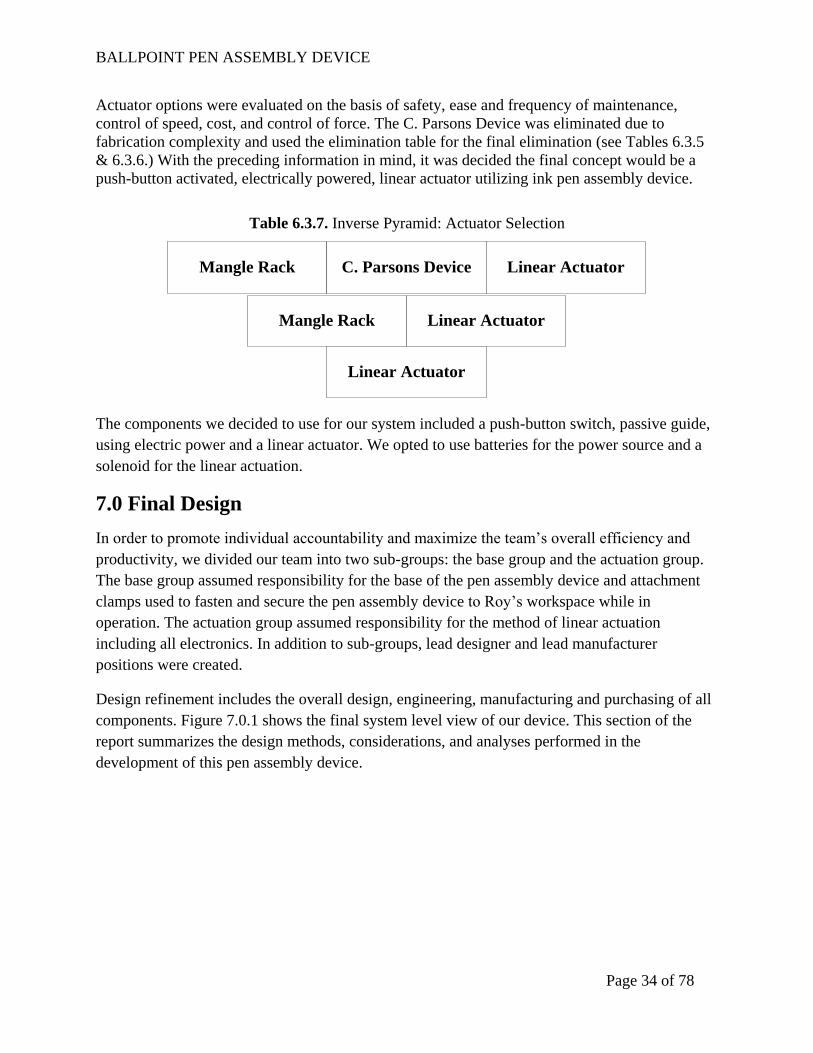
Actuator options were evaluated on the basis of safety, ease and frequency of maintenance,
control of speed, cost, and control of force. The C. Parsons Device was eliminated due to
fabrication complexity and used the elimination table for the final elimination (see Tables 6.3.5
& 6.3.6.) With the preceding information in mind, it was decided the final concept would be a
push-button activated, electrically powered, linear actuator utilizing ink pen assembly device.
Table 6.3.7. Inverse Pyramid: Actuator Selection
Mangle Rack C. Parsons Device Linear Actuator
Mangle Rack Linear Actuator
Linear Actuator
The components we decided to use for our system included a push-button switch, passive guide,
using electric power and a linear actuator. We opted to use batteries for the power source and a
solenoid for the linear actuation.
7.0 Final Design
In order to promote individual accountability and maximize the team’s overall efficiency and
productivity, we divided our team into two sub-groups: the base group and the actuation group.
The base group assumed responsibility for the base of the pen assembly device and attachment
clamps used to fasten and secure the pen assembly device to Roy’s workspace while in
operation. The actuation group assumed responsibility for the method of linear actuation
including all electronics. In addition to sub-groups, lead designer and lead manufacturer
positions were created.
Design refinement includes the overall design, engineering, manufacturing and purchasing of all
components. Figure 7.0.1 shows the final system level view of our device. This section of the
report summarizes the design methods, considerations, and analyses performed in the
development of this pen assembly device.

BALLPOINT PEN ASSEMBLY DEVICE
Page 35 of 78
Figure 7.0.1. Overall System Design
7.0.1 Heuristic-Based Design Techniques
We used heuristic-based design techniques throughout our design process. Using heuristic
techniques, we reduced the time it took to solve problems and make decisions. Techniques that
were utilized include value engineering, design for safety, and mock-ups.
7.0.1.1 Value Engineering
Value engineering was helpful in the selection of base materials as well as choosing a pressing
device. Initial pressing device concepts, shown above in Figure 5.2.1, included an electronic
linear actuator and a small DC motor that could be added to a slider-crank-style linkage. We
discovered that most electronic linear actuators were too expensive for our budget and that DC
motors required expensive and complex controllers and/or linkages. Also, electronic linear
actuators would have taken up too much critical space on Roy’s work station. Buying either of
these actuation systems would have required months worth of Roy’s work just to make up for the
high cost.
Handles
Push-Button
Activation
Solenoid
Damper
Battery
Pre-
Assembly
Hand Guide
Draw-Latch

BALLPOINT PEN ASSEMBLY DEVICE
Page 36 of 78
Another idea for the pressing device included a manually-operated press, which would have only
required a piston and handle assembly. While this assembly would have been inexpensive, it
would have defeated the purpose of reducing Roy’s physical strain. Since actuation force
reducing options were severely limited by Roy’s poor and declining range of motion and
dexterity, a push-pull 24-V solenoid was selected for the pressing mechanism.
A solenoid, shown below in Figure 7.0.1.1.1, is an electrical device which operates by energizing
an inductive coil. An electromagnetic field is created around a steel cylinder that moves it in one
direction through the inductive coil. This will drastically reduce the strain on Roy, as he will
only be required to press one button for the solenoid to operate. Additionally, timing and
reversing circuits are not required to operate the solenoid. It can be wired directly to a power
supply through a switch, further reducing costs.
Figure 7.0.1.1.1. Selected Actuation Method: Push-Pull Solenoid
7.0.1.2 Design for Safety
Safety was a high priority throughout our design process. Due to the physical condition of our
customer, an increased demand for safety was required. One of the greatest safety measures
included not having any sharp areas or pinch points on our device. To eliminate sharp areas, all
corners and edges were chamfered or rounded. An example of rounded edges on our device can
be seen in Figure 7.0.1.2.1, shown below. To eliminate pinch points, the solenoid and holding
block were located such that it would be impossible for Roy to place his hand in a possible
pinching zone. Additionally, all electrical components were enclosed and no wiring was exposed
in order to decrease the possibility of shock.
Our original design required a plug to be inserted into any standard 110 VAC wall socket,
however, Atco is forbidden from using extension cords by OSHA. For this reason, it was
decided that using a battery as a power source was be the best way to protect Roy and other Atco
employees.

BALLPOINT PEN ASSEMBLY DEVICE
Page 37 of 78
Figure 7.0.1.2.1. Rounded Corners of Pen Assembly Device
Another safety consideration in the ProPoint workshop was a potential fall hazard. A fall hazard
was defined by the pen assembly device falling from Roy’s work station and potentially causing
injury to Roy or other Atco employees. To address this concern, a clamping device was used to
secure the pen assembly device to Roy’s work station. The clamping device is pictured below in
Figure 7.0.1.2.2.
Figure 7.0.1.2.2. Clamps Used to Secure Pen Assembly Device to Work Station

BALLPOINT PEN ASSEMBLY DEVICE
Page 38 of 78
7.0.1.3 Mock-Ups
Two mock-ups were designed and built for experimentation and proof of concept. The template
shown below in Table 7.0.1.3.1 was used to guide the mock-up process. The mock-ups are
illustrated below in Figures 7.0.1.3.1 and 7.0.1.3.2.
Table 7.0.1.3.1. Template used for Mock-Ups
Name Type Relationship to Customer Needs Materials Used Cost ($) Build Time
Mock-Up 1 Physical Balsa Wood 10 3 hours
Mock-Up 2 Physical Scrap Wood 0 2 hours
Address dexterity issues and proof of
concept
Figure 7.0.1.3.1. Mock-Up 1 Figure 7.0.1.3.2. Mock-Up 2
Mock-up 1 featured a rotating pen cylinder housing device. This device was created to aid Roy’s
difficulty of using two hands to insert the ink pen cartridge into the pen cylinder. Starting with
the pen cylinder housing device in the vertical position, Roy would place the pen cylinder in the
cylindrical slot. Next, Roy would slide the ink pen cartridge into the pen cylinder, with the pen
cylinder still placed the pen cylinder housing device. Next, he would rotate the pen cylinder
housing device 90° such that the pen cylinder housing device is lined up with the linear actuator.
For simplification, a box was used to replicate the housing of a linear actuator. After the pen
cylinder housing device was lined up with the linear actuator, Roy would push a button to
engage the linear actuator. The actuator would press the ink pen cartridge into the pen cylinder.
Upon completion of pressing, Roy would rotate the pen cylinder housing device back to the
initial vertical starting position and remove the assembled pen.
Mock-up 2 contained a pre-assembly fixture also to address Roy’s difficulty of using two hands
to insert the ink pen cartridge into the pen cylinder. Using this mock-up, Roy would first place a
pen cylinder in the pre-assembly fixture, orienting the open end of the pen cylinder to his left.
Next, Roy would slide an ink pen cartridge into the pen cylinder. The required tolerances to
allow the ink pen cartridge to slide into the pen cylinder were considerably tight, but they were
required in order for the pre-assembly fixture to be effective. After pre-assembling the ink pen,
Roy would then move the pen to the pressing area. Like Mock-up 1, a button would be used to

BALLPOINT PEN ASSEMBLY DEVICE
Page 39 of 78
engage a solenoid to press the ink pen cartridge into the pen cylinder thus completing the pen
assembly.
7.0.2 Failure Modes and Effects Analysis (FMEA)
Conducting an FMEA evaluation helped us determine the most probable causes of failure.
Methods of failure we considered were not limited to operational use. Failure could occur even
while the pen assembly device is not in operation. For a complete list of failure modes and
effects, refer to Appendix D.
The two failure results with the largest risk priority numbers (RPNs) were loss of power due to
failure within the electrical system and the failure of a timing circuit within the electrical system.
In order to correct these problems, we simplified the electrical circuit by removing many
components that were unnecessary for operation. The circuit was simplified to three components:
the power source (battery), the actuator (solenoid), and the button. The simplicity of the final
circuit design allows for simple troubleshooting of any error within the electrical circuit.
7.0.3 Design for Manufacturing and Assembly (DFMA)
We considered several factors that were pertinent for a DFMA. From our initial to our final
design, we made several manufacturing-related decisions. These decisions ranged from simple
fasteners to major changes, such as reorienting the layout of the system. Our initial design was
simple and manufacturing friendly, but after tests with Roy, we found that the design had to be
unique to accommodate his severe physical limitations.
One of our primary goals for DFMA was to manufacture as few parts as possible to keep the
material and labor costs low. Other ways we tried to keep material and labor costs low was
through material type and part geometry. At the start of our design process we were able to select
a material that would meet or exceed our design requirements at relatively low cost. Several
materials and their properties are listed in Table 7.0.3.1 that aided us through the material
selection stages of our design process. From Table 7.0.3.1, we were able to choose our base
material for the pen assembly device; that material was PVC.
Part geometry was also taken into consideration when developing our design. There were many
complex geometrical shapes in our initial design. To simplify our design, we modified parts that
were difficult to machine. As the project continued we considered all possibilities that kept
manufacturing simple. The less time consuming and difficult the machining, the more we save
on manufacturing cost.
The DFMA for our current electronic system started in the beginning with a pneumatic cylinder
for our pressing operation. This idea was a problem for several reasons. First, it required too
many components for the system to work. Second, Atco had no air connections around Roy’s
work area. The pneumatic system would require several components to actuate the cylinder, such
as electric solenoid valves, speed reducers, air lines, air fittings, and regulators. The cost for this

BALLPOINT PEN ASSEMBLY DEVICE
Page 40 of 78
system started increase with time. We eliminated the pneumatic idea and started looking into an
electric linear actuator. At first this seemed like a feasible solution, until we realized the added
amount of extra components we would need to build this system. The control system for each
actuation method was considered and simplified along the way as well. The pneumatic cylinder
had a control system comprising either a two-way valve or an electric reversing solenoid, both of
which were expensive and complex. For the linear actuator or mangle rack, a circuit board with a
timer chip and the ability to reverse direction would have been a required purchase. All of these
options were expensive and complex. The pen assembly device’s control system was simplified
to a normally open, momentary switch and the power source. After performing research, we
found a solenoid that matched our specifications and requirements. The solenoid was also very
low in price. Another consideration that we used for our final design was to change the 110-VAC
wall source to a 24-V battery source. The battery will eliminate the use of a transformer. The
disadvantages of using a battery is that took up valuable space and will need to be replaced in the
future.
Table 7.0.3.1. Material Properties for Base Selection
7.1 Pen Assembly Device Operation
The pen-making process at Atco consists of several steps. Atco starts with the raw materials to
make ballpoint pens, such as ink, plastic ink cartridges, plastic pen cylinders, and plastic pen
caps. Our pen assembly device was designed to perform one of the many steps needed to
produce a pen: the pressing operation. Roy receives two pen parts at his station: the ink pen
cartridge and the pen cylinder with non-writing end already pressed, as shown in Figure 2.0.1.
Roy’s job is to press the ink pen cartridge into the pen cylinder. The ink pen cartridges and pen
cylinders arrive at Roy’s station in separate boxes. Roy will take one ink pen cartridge and one
pen cylinder to press in the pen assembly device. Operation of the pen assembly device consists
of two phases: pre-assembly and pressing the pen.

BALLPOINT PEN ASSEMBLY DEVICE
Page 41 of 78
Figure 7.1.1. Pre-assembly and Pressing Areas of Pen Assembly Device
7.1.1 Pre-Assembly Phase
In the pre-assembly phase, the ink pen cartridge will be inserted, but not fully pressed, into the
pen cylinder, as shown above in Figure 7.1.1.1. One of the most time consuming tasks in Roy’s
process is aligning the ink pen cartridge to fit inside of the pen cartridge before the pressing
operation. To reduce the time it takes to do this, we have created an alignment fixture that
eliminates the need for Roy to use both of his hands. Roy will take a pen cylinder from the box
and place it in the designated slot on the right side of the device with the open end of the cylinder
facing left.
Next, Roy will take an ink pen cartridge from the box, place it on the surface of the pre-assembly
fixture, and slide it with one hand into the pen cylinder. As the cartridge slides across the surface
it is guided into the pen cylinder by two triangular shaped guides as seen in Figure 7.1.1.1. After
the pen is pre-assembled it will need to be transferred to the pen pressing fixture. To assist with
this movement we have added a ramp large enough for an average size male hand which can also
be observed in Figure 7.1.1.1. This ramp will allow Roy to gain better access to the pre-
assembled pen and the pen pressing fixture. Once the cartridge has been pre-assembled into the
pen cylinder the part can then be moved onto the next phase of the ink pen assembly process.
Pre-Assembly Ink Cartridge Guides
Ramps to Assist Movement of Part

BALLPOINT PEN ASSEMBLY DEVICE
Page 42 of 78
Figure 7.1.1.1. Pen Placed in Pre-Assembly Fixture
7.1.2 Pressing Phase
The pen pressing process first starts from the finished pre-assembly phase. The pen can now be
moved up the ramps shown in Figure 7.1.1.1 into the holding blocks for the pressing operation.
When the pre-assembled pen is in the correct position for pressing an activation button is
pressed. The button controls an electrical solenoid that actuates, completely pressing the ink
cartridge into the pen cylinder. The force applied to the pen is controlled with a shock absorber.
From testing, the solenoid output over a pound of force for some trials. The shock absorber will
only allow one pound of force to be applied to the pen at all times of the pressing operation.
The electrical system that controls the solenoid uses a simple open-closed electrical circuit
powered by a 24 volt rechargeable battery. Once the pen has been assembled completely it is
removed from the pressing holding blocks and moved to an assembled parts bin for the Atco
administrators to collect.
7.1.2 Maintenance and Service
There are two maintenance tasks that need to be performed on a regular basis. One is to keep the
surface and electrical components free of debris and dust. The other is to replace the battery in
the device daily with a battery that is fully charged. Completing these two simple maintenance
requirements on a consistent basis will ensure the longevity of the pen assembly device.
If a part on our device breaks or needs to be replaced, whether it is a purchased part or a
machined part, the included manual shall be consulted. All machined parts were attached using a
Ramps to Assist Movement of Part

BALLPOINT PEN ASSEMBLY DEVICE
Page 43 of 78
PVC compound adhesive. To replace a machined part on the device, the included CAD drawings
should be used to accurately align the part to its original position.
Figure 7.1.2.1. Targeted Maintenance and Service Areas of Pen Assembly Device
One replacement part for each machined part will be included with the device. The electrical
components of the jig can be replaced simply by ordering a new part from the respected vendors
listed in the included manual, and in Appendix A of this report. All of the locations for the
electrical components are also shown in the included CAD drawings. A wiring diagram will be
provided, as well, in the case that a short circuit occurs.
7.2 Manufacturing Details
This section seeks to provide step-by-step procedural instructions on how our pen assembly
device can be reproduced. All manufacturing and assembly was performed in Stocker Center in
Athens, Ohio.
7.2.1 Handles
To make the two handles for the device, shown below in Figure 7.2.1.1, start with the ¾” thick
PVC stock. The handles are 6”T X 5”W and are cut to size using a vertical mill. The cutout for
the handle is milled using a 1” endmill. The rounded edges at the top corners of each handle are
created by using a template to trace the radius. Use a vertical bandsaw to cut the rounds, then a
metal file and steel wool to polish the surface. The holes for fastening the handles to the base of
the device required two steps: a drill press to make the through-holes and a vertical mill or drill
press to make the counterbores for the heads of the fasteners. Details for attaching the handles to
the base are outlined in the “Assembly” section.
Battery Must Be Charged Regularly
Areas That Must Be Free of Debris

BALLPOINT PEN ASSEMBLY DEVICE
Page 44 of 78
Figure 7.2.1.1. Handle of Pen Assembly Device
7.2.2 Base
The first step in making the base of the pen assembly device (Figure 7.2.2.1) is to obtain the ¾”
thick PVC stock. The base dimensions are 22”L X 5”W and is cut to size using a vertical
bandsaw. The next step is to use the vertical mill to machine the cutouts for the solenoid, pre-
assembly, and hand ramp. A ½” endmill is used for all cutouts but it is important to note that the
cutout for the solenoid is a plunge cut; therefore, the endmill must have all flutes come to a point
in the center.
Figure 7.2.2.1. Base of Pen Assembly Device
The next step requires a 3/8” ball mill to make the groove for holding the pen barrel in the pre-
assembly area. The next step is to use a 3/8 ” endmill to make the groove on the back edge of the
base for the electrical wires. Another groove is milled just to the right of the pen barrel groove
using a 1/8 ”endmill. This groove holds the pre-assembly stopping guide so it is easier to move
the pen from the pre-assembly area to the holding block. The final step is to drill two holes on
each side edge for the fasteners. This is done by lining up the handles with the base and drilling
pilot holes for the self-taping fasteners.
7.2.3 Inserts
The inserts include the following: hand ramp, pre-assembly ramps (x2), pre-assembly insertion
guides (x2), holding blocks (x2), stopper guide for pre-assembly, and cover for the wires.

BALLPOINT PEN ASSEMBLY DEVICE
Page 45 of 78
To make the hand ramp, cut a 3.5”X3.5” piece of ¾” stock PVC using a vertical bandsaw. On
the vertical mill, attach the flat vise onto a tilting vise and set the tilt angle o 12° (see Figure
7.2.3.1). Place the 3.5”X3.5” piece into the vise and mill the entire surface. Cut the ramp to size
using a vertical bandsaw. Round off all of the edges using a sanding wheel and or metal file.
Figure 7.2.3.1. Tilting Vise with Hand Ramp
For the two pre-assembly ramps, use a vertical bandsaw to cut a 1”W X 3”L piece of PVC.
Adjust the tilt angle to 12° and machine the entire surface evenly. Use a vertical bandsaw to cut
the two ramps to their specified size.
For the two insertion guides, use a vertical mill to create a 2”W X 6”L X 1/8”T piece of PVC.
Cut the triangular guides to size using a vertical bandsaw and round all edges using a sanding
wheel and/or metal file (see Figure 7.2.3.2). Save the scrap material for the stopper guide.

BALLPOINT PEN ASSEMBLY DEVICE
Page 46 of 78
Figure 7.2.3.2. Insertion Guide
To make the holding blocks, use a vertical mill to create a 1”W X 3”L X ¼”T piece of PVC. Use
the 3/8” ball mill to cut a groove in the center of the part at the specified depth. Cut each part to
length using the vertical bandsaw (see Figure 7.2.3.3).
Figure 7.2.3.3. Machining Holding Blocks
Using scrap material from the insertion guides, cut the stopper guide to its specified dimensions
on the vertical bandsaw. Round all edges using sandpaper and/or metal file.
The cover for the wires is made using 22”L X ¾”W X 1/8”T PVC. Drill five
1/4” holes in the
center of the cover, spaced evenly apart. Countersink the holes using a 45° chamfer bit.

BALLPOINT PEN ASSEMBLY DEVICE
Page 47 of 78
7.2.4 Damper Housing Block
Cut the housing block for the damper (Figure 7.2.4) to its specified dimensions using the vertical
bandsaw. Using a drill press or vertical mill, use a 19
/64” drill bit to make the tap drill hole for the
damper. Next, use the specified metric tap (M8 X 0.75) to thread the hole completely through.
Next, use a #48 drill bit to make two holes at the outside center of the block for the fasteners.
Use a #19 drill bit to make the counterbore for each hole to hide the fastener head. Thread the
damper into the block and fasten the nut on the backside. Round off all of the edges using
sandpaper and or a metal file.
Figure 7.2.4.1. Damper Block for Pen Assembly Device
7.2.5 Junction Boxes
The electrical components consist of the following: junction box (x2), push-button, solenoid,
battery holder, wire, and terminal block.
The push-button housing is a 4” X 4” X 2” PVC junction box. Drill a 1” hole in the center of one
of the 2” wide sides. On the opposite side of the box, towards the bottom, drill a ½” hole for the
cord grip (P/N CG-1) to feed the wires through the box. Insert the button and cord grip and re-
attach the cover.
The other 4” X 4” X 2” PVC junction box is for the battery holder and terminal block. Drill a
pilot hole and use two self-tapping screws to attach the terminal block to the bottom of the
junction box. For the battery holder, take the cordless drill (where the matching battery comes
from) and use a vertical bandsaw to cut off the part where the battery is attached (see Figure
7.2.5.1). Make sure the conductive steel clips are not damaged. Next, use the vertical mill to
make a cutout in the junction box cover that is slightly larger than the drill handle.
Figure 7.2.5.1. Battery Configuration on Pen Assembly Device

BALLPOINT PEN ASSEMBLY DEVICE
Page 48 of 78
7.2.6 Circuit Wiring
A simplified wiring diagram is shown below, figure 7.2.6.1. All components except the switch
and the solenoid are located inside the battery box. All electrical connections are made via a
terminal block, noted as 12VDC Battery on the simplified wiring diagram.
Figure 7.2.6.1. Simplified Wiring Diagram
To wire the electrical system, first take the terminal block and remove the screws on terminal 3
and 7, remove the metal bracket with e small screwdriver, and cut the bracket in half with wire
cutters. Make sure to trim the bracket to ensure about 1/16” gap between the two halves when it is
installed again. Connect terminals 6 to terminal 7 and terminal 3 to terminal 4 using jumpers, as
shown below in figure 7.2.6.2.
Figure 7.2.6.2. Terminal Block Terminals
1 2 3 4
5 6 1
1
7 8
3-4 Jumper
6-7 Jumper

BALLPOINT PEN ASSEMBLY DEVICE
Page 49 of 78
Cut all required wires to appropriate lengths. There should be 2 wires cut to approximately 30”
and 4 wires cut to approximately 7”. The wires included with the solenoid should be long enough
to reach the battery box and connect to the terminal block. Run the wires from the switchbox and
solenoid to the battery box through the appropriate holes and groves in the boxes and base, as
shown in figure 7.2.6.3. The wires from the switch are shown in blue and the solenoid wires are
shown in red. The switch wires are inserted through a cord grip mounted to the rear of the switch
box and the solenoid wires are routed through a hole in the base from the solenoid cutout to the
wire groove. Both wires are then inserted through the hole in the rear of the battery box.
Figure 7.2.6.3. Wire Routing
Solder 7” extensions to the wires leading from the battery socket (from the cordless drill handle)
and to the backup DC plug. Attach the spade terminals to the end of each of the remaining wires,
ten in all, by crimping or soldering. Attach the spade terminals to the terminal block as shown in
figure 7.2.6.2 and table 7.2.6.1. Insert the wires to the switch box into the groove at the back of
the base and screw in the wire cover. Close both junciton boxes with the provided screws, insert
a battery into the battery holder, and push the red button to test the actuator
Table 7.2.6.1: Terminal Block Wiring Connections
Terminal Wire
1 Momentary Switch Output 2 Momentary Switch Input
3 Rechargeable Battery Negative Terminal
4 Backup DC Jack Negative Terminal
5 Solenoid Connection 1
6 Rechargeable Battery Positive Terminal
7 Backup DC Jack Positive Terminal
8 Solenoid Connection 2

BALLPOINT PEN ASSEMBLY DEVICE
Page 50 of 78
7.2.7 Assembly
Before any assembly begins, make sure all exposed edges and corners are rounded and smooth to
the touch. Make sure all surfaces are clean and clear of any debris. Apply PVC cement to the
bottom surface of each insert and to each insert’s respective location on the base of the device.
Wipe off all excess cement.
A crucial step in the assembly process is the alignment of the solenoid and damper. To do this
properly, take a pen barrel with ink cartridge inserted but not pressed and place on the holding
block. Next, align the center of the solenoid push-rod and damper so that it is perfectly aligned
with the center of the pen and use a center-punch to indicate the exact location of the holes for
attaching each. It is important to note that the damper’s location needs to be just to the left of the
pen tip when it is in the pre-assembly. The solenoid holes are drilled completely through the
base. Countersink the holes from the bottom of the base. Use a #29 tap drill for the damper holes
in the base but do not go completely through the base. Next, use an 8-32 tap and thread the holes
as deep as possible. Fasten the damper block to the base using 8-32 bolts.
Figure 7.2.7.1. Attaching Solenoid to Base
To attach the two junction boxes to the base, drill pilot holes in their specified location and use
self-tapping screws.
The final step in assembling the device is to attach the base clamps, or draw latches (P/N DL-1,
DL-2). Drill pilot holes on the outside of the handles at their specified locations and use self-
tapping screws to attach the clamps.
7.4 Design Validation through Test Results and Operating Experience
To evaluate our assembly device honestly and fairly to verify that we met the customer
requirements, formal testing was conducted.

BALLPOINT PEN ASSEMBLY DEVICE
Page 51 of 78
7.4.1 Voltage vs. Force Test
The purpose of this test was to validate the solenoid we bought. This test related voltage to force,
simulating how the pen assembly device would act as the battery ran down and whether the
actual force generated by the solenoid is appropriate for our application. A return spring was
added to the solenoid to return the solenoid plunger to the retracted position which slightly
reduced the actuation force.
0.0
5.0
10.0
15.0
20.0
25.0
30.0
35.0
40.0
45.0
0 5 10 15 20 25 30 35 40 45
Fo
rce
(lb
s)
Volts (V DC)
PushingHolding
Figure 7.4.1.1. Test Results: Solenoid Force vs. Voltage
7.4.2 Customer Requirements Verification
All customer requirements have been met, by means of verification through formal testing.
Roy’s physical condition is declining with time. At eighty years of age, Roy’s physical condition
would be difficult to consistently measure over a long-term period. For the sake of this project in
determining Roy’s change in comfort level, we evaluated Roy’s physical strain over several one-
day trials to meet the specification. However, to validate that we met the requirement of reducing
his strain over a long-term period, more testing is required.
All customer needs were qualitatively and quantitatively evaluated for verification through
formal testing at ProPoint with Roy. A summary of the results is shown below in Table 7.4.2.1.

BALLPOINT PEN ASSEMBLY DEVICE
Page 52 of 78
Table 7.4.2.1. Customer Needs Verification
# Need Verification 1 No exposed gears, pinch points or fast-moving parts YES
2 High cycle life YES
3 Simple and safe to load, unload and operate YES
4 Low maintenance YES
5 Fit ProPoint table (1.0 x 0.5 m) YES
6 Low total cost (procurement and operation) YES
7 Increase operator productivity YES
8 Decrease physical stress on operator YES
9 Able to be operated ambidextrously YES
Customer specifications were qualitatively and quantitatively evaluated for verification through
formal testing at ProPoint with Roy. A summary of the results is shown below in Table 7.4.2.2.
Table 7.4.2.2. Customer Specifications Verification
# Specification Verification 1 Increase Roy's productivity 55%
2 Decrease Roy's physical stain YES
3 Not contain any exposed gears or pinch points YES
4 Not exceed the cost of $300 $209.75
5 Fit on Roy's work station (0.5 x 0.25 m) YES
7.4.3 Quantitative Improvements
There were two key quantitative improvements that our assembly device boasts over the old jig:
assembly time per pen and set-up time. It took Roy 11 minutes, on average, to press one pen
using ProPoint’s old assembly jig. Using our assembly device, it takes Roy approximately 4
minutes per pen. This accounts for a 55% increase in productivity.
It took Atco officials 4 minutes, on average, to set up ProPoint’s old assembly jig. Setup time
included manually clamping the assembly device to Roy’s desk via C-clamps. Our assembly
device design utilized draw-latches that reduced set-up time by 3 minutes, or 75%. Figure 7.4.3.1
illustrates these significant improvements.

BALLPOINT PEN ASSEMBLY DEVICE
Page 53 of 78
0
2
4
6
8
10
12
Assembly Time (Per Pen)
Tim
e (m
inu
tes)
Set-Up TimeAssembly Time (Per Pen)
55%
75%
Figure 7.4.3.1. Significant Quantitative Improvements with Our Device
7.4.4 Qualitative Improvements
Along with improving Roy’s productivity, our device improved Roy’s work experience by
reducing the physical strain required to perform his job. Instead of Roy having to insert the ink
cartridge into the barrel with two hands, the pre-assembly feature of our design assists Roy by
helping to guide the ink cartridge into the barrel. The pre-assembly fixture also requires only one
hand.
The need to use a toggle-clamp mechanism to press the pen together is no longer required with
our device. This eliminates the need for Roy to struggle to press a pen. Our device includes a
push-button that is used to activate the solenoid that is used to press the pen.
7.4.5 Customer Influence on Design Process
We have conducted several interviews with Atco/ProPoint associates and visitations with our
intended operator, Roy. Atco/ProPoint associates were interviewed to get their input on our latest
design features. Their input was always considered, and in most cases used to modify the design
of the pen assembly device. Visitations with Roy consisted of testing our latest mock-up
modifications to help us ensure our design maximizes Roy’s productiveness while remaining
ergonomically effective.

BALLPOINT PEN ASSEMBLY DEVICE
Page 54 of 78
Figure 7.4.5.1. Evolution of Our Pen Assembly Device
8.0 Conclusions
The objective of our project was to improve the work experience of an NPA employee, Roy,
while satisfying the requirements for NISH’s National Scholar Award for Workplace Innovation
& Design. We succeeded in accomplishing this objective through creating a new pen assembly
device (Figure 8.0.1) for Roy that satisfied all customer requirements, including needs and
specifications.
Figure 8.0.1. Final System-Level Design
Our final design addressed Roy’s difficulty using the old pen assembly device on a quantitative
and qualitative basis. Several unique features of our assembly device, shown above in Figure
8.0.1, enabled the device to be deemed effective by Atco associates.
The pre-assembly fixture on our assembly device accounted for 55% increase in productivity by
aiding Roy’s ability to load ink pen cartridges into pen barrels. A task that used to take him
approximately four minutes with the old assembly device now takes him, on average, two
minutes to complete.

BALLPOINT PEN ASSEMBLY DEVICE
Page 55 of 78
Ramps for Roy’s hand and the pen were created to assist him with moving the pre-assembled pen
to the pressing device. A simple solenoid was used as the actuating device and was paired with a
damper to limit the maximum force and a large push-button for activation. A rechargeable
battery powers the assembly device with an included spare. For back-up purposes, our device has
the capability to be plugged into any wall socket. For set-up ease, easy-to-grab handles were
installed and draw-latches were attached. Setting up the old jig required C-clamps and took
approximately 4 minutes. The draw-latch clamps on our device reduced the set-up time to one
minute, which accounts for a 75% decrease.
The most important result of this project was the satisfaction of our customer. The Atco
associates that worked side-by-side with us to ensure a quality product approved our device and
are ready for implementation in the ProPoint workshop. The device also has the approval of the
intended operator. Roy’s input throughout the design process helped us optimize his comfort and
productivity, and solidified his consent to use our final product.

BALLPOINT PEN ASSEMBLY DEVICE
Page 56 of 78
References
1. Dixon, K.A.. "Restricted Access: A Survey of Employers About People with Disabilities
Press Release." 01 Mar 2003, 11 Nov 2008 <http://www.heldrich.rutgers.edu/uploadedFiles/
Publications/Restricted%20Access.pdf>.
2. Dixon, K.A.. "Toward the Accessible Workplace: Strategies for Competitive Employment
Among New Jerseyans with Disabilities." 01 Dec 2003, 05 Nov 2008
<http://www.heldrich.rutgers.edu/uploadedFiles/Publications/Toward%20More%20Accessib
le%20Workplace.pdf>.
3. Jones, Cynthia. "Economics and People with Disabilities ." 01 May 2004 12 Oct 2008
<http://www.accessiblesociety.org/topics/economics-employment/index.htm>.
4. NISH, "NISH National Scholar Award for Workplace Innovation & Design 2007/2008
Application Packet." Sep 2007, 8 Jun 2008
<http://www.nish.org/NISH/Doc/0/5U2D0QHKEHLK7EFBE783SE8T18/Scholar%20Appli
cation%202007%202008.pdf>.
5. About Atco, Inc., 2007, Atco, Inc., Athens, OH, 2 April 2008,
<http://atcoinc.org/aboutpg.htm>.
6. About ProPoint, 2003, ProPoint a division of Atco, Inc., Athens, OH, 2 April 2008,
<http://propoint.org/mm5/merchant.mvc?Screen=ABT&Store_Code=P>.
7. Penn State Industries, "Penn State Pen Press." Sep 2007 8 Jun 2008
<www.psischools.com/graphics_school/Pen-press.jpg>.
8. Sakurai, Terushige, Press Machine, 1987, United States Patent Office, Washington, DC, 2
April 2008,
<http://www.google.com/patents?id=oIg4AAAAEBAJ&pg=PA3&lpg=PA3&dq=4,648,786+
patent&source=web&ots=JTT_VgELDe&sig=KmM1arMne6Ns3cH66zgU90sWkeo&hl=en
#PPP1,M1>
9. Occupational Safety & Health Administration, "Machine Guarding." Safety and Health
Topics 06 Dec 2007 6 Jun 2008 <http://www.osha.gov/SLTC/machineguarding/index.html>.

BALLPOINT PEN ASSEMBLY DEVICE
Page 57 of 78
Appendix A: Assembly Parts List and Bill of Materials
Table A1. Parts List
Part # Description Subassembly Group Drawing # DL-1 Draw Latch, Left Safety N/A DL-2 Draw Latch, Right Safety N/A HL-1 Handle, Right Safety HL-1 HL-2 Handle, Left Safety HL-2 BS-1 Base Assembly BS-1 MS-1 Momentary Switch Electrical N/A CG-1 Cord Grip Electrical N/A JB-1 Button Box Electrical JB-1 BL-1 Button Box Lid Electrical N/A JB-2 Battery Box Electrical JB-2 BL-2 Battery Box Lid Electrical BL-2 TB-1 Terminal Block Electrical N/A PP-1 Backup Power Plug Socket Electrical N/A BH-1 Battery Holder Electrical N/A RB-1 Rechargeable Battery Electrical N/A WC-1 Wire Cover Electrical WC-1 PS-1 Push Solenoid Electrical N/A PR-1 Preassembly Ramp, Front Preassembly PR-1 PR-2 Preassembly Ramp, Rear Preassembly PR-2 MR-1 Main Ramp Preassembly MR-1 BK-1 Backstop Preassembly BK-1 TR-1 Transition Ramp, Right Assembly TR-1 TR-2 Transition Ramp, Left Assembly TR-2 PC-1 Pen Cradle, Right Assembly PC-1 PC-2 Pen Cradle, Left Assembly PC-2 DB-1 Damper Block Assembly N/A
DL-1
HL-1 JB-1 CG-1
MS-1
BL-1
BS-1
PR-1
MR-1 BK-1 DL-2
HL-2
JB-2
PP-1
WC-1 TB-1
BL-2
BH-1
RB-1
PS-1
PR-2
PC-1 TR-1
PC-2
DB-1
TR-2

BALLPOINT PEN ASSEMBLY DEVICE
Page 58 of 78
Table A2. Bill of Materials Vendor Vendor Part # Description Associated Assembly Part #'s Price Quantity Total
McMaster-Carr 7527K44 Terminal Block 4 Circuits TB-1 $1.43 1 $1.43
McMaster-Carr 7527K59 Jumper for 0.38" Terminal Block TB-1 $2.15 1 $2.15
McMaster-Carr 7869K131 Flanged Spade Terminal (10 pack) TB-1 $3.52 1 $3.52
McMaster-Carr 3692K11 Standard Shock Absorber M8 X 0.75" DB-1 $28.13 1 $28.13
McMaster-Carr 8747K129 PVC (Type I) Sheet 3/4" Thick, 12" X 24"
BS-1, HL-1, HL-2, MR-1, TR-1, TR-
2, PC-1, PC-2 54.68 1 $54.68
McMaster-Carr 8747K124 PVC (Type I) Sheet 1/8" Thick, 12" X 24" PR-1, PR-2, WC-1, BK-1 $8.40 1 $8.40
McMaster-Carr 1863A21 Draw Latch Zinc Plated Steel, 1.5" DL-1, DL-2 $5.73 2 $11.46
McMaster-Carr 6907K8 Nickel-Plated Brass Liquid-Tight Cord Grip CG-1 $4.64 1 $4.64
McMaster-Carr 91771A148 Flat Head Machine Screw 6-32, 1/2" L PS-1 $0.05 4 $0.20
McMaster-Carr 91831A007 Nylon-Insert Locknut 6-32, 5/16" Width PS-1 $0.06 4 $0.24
McMaster-Carr 92210A197 Flat Head Sckt Cap Screw 8-32, 3/4" L WC-1 $0.11 5 $0.55
McMaster-Carr 92325A311 Pan Head Screw SS Self Tapping, 1/2" L JB-1, JB-2, DL-1, DL-2 $0.10 10 $0.99
McMaster-Carr 91794A115 Fillister Head Machine Screw 4-40, 1" L DB-1 $0.08 2 $0.16
McMaster-Carr 90390A545 Torx Thrd-Cut Screw , 1/4"-20, 1-1/2" L HL-1, HL-2 $0.14 4 $0.56
NewarkInOne 74K3604 65mm Mushroom Pushbutton Switch JB-1 $27.12 1 $27.12
Radio Shack N/A 5.5mm DC Power Socket JB-2 $1.99 1 $1.99
Jameco 262191CB Tubular Solenoid, 24 VDC, 18mm BS-1 $23.95 1 $23.95
EDMWI.com 21009-CHIG0018 Cordless Drill (24V Rechargeable Battery) JB-2, BL-2 $23.08 1 $23.08
Lowes N/A PVC Cement BS-1 $3.50 1 $3.50
Lowes N/A Junction Box (4"x4"x2") JB-1, JB-2, BL-1, BL-2 $6.50 2 $13.00
Total $209.75

BALLPOINT PEN ASSEMBLY DEVICE
Page 59 of 78
Appendix B: Part Drawings

BALLPOINT PEN ASSEMBLY DEVICE
Page 60 of 78

BALLPOINT PEN ASSEMBLY DEVICE
Page 61 of 78

BALLPOINT PEN ASSEMBLY DEVICE
Page 62 of 78

BALLPOINT PEN ASSEMBLY DEVICE
Page 63 of 78

BALLPOINT PEN ASSEMBLY DEVICE
Page 64 of 78

BALLPOINT PEN ASSEMBLY DEVICE
Page 65 of 78

BALLPOINT PEN ASSEMBLY DEVICE
Page 66 of 78

BALLPOINT PEN ASSEMBLY DEVICE
Page 67 of 78

BALLPOINT PEN ASSEMBLY DEVICE
Page 68 of 78

BALLPOINT PEN ASSEMBLY DEVICE
Page 69 of 78

BALLPOINT PEN ASSEMBLY DEVICE
Page 70 of 78

BALLPOINT PEN ASSEMBLY DEVICE
Page 71 of 78

BALLPOINT PEN ASSEMBLY DEVICE
Page 72 of 78
Appendix C: Interview Guide
Questions for ATCO (10/11/2007)
1. Would a newer, slightly more automated device increase individual wages based on
higher productivity?
Yes
2. Do you have compressed air plumbing in your facilities?
Yes
3. How many companies like ProPoint exist? (exist at PERCO, WASHCO, etc.?)
None (that they know of)
4. Would it be beneficial to have the ability to perform more than one assembly stop on a single
device?
Yes (reluctantly)
5. Would you like accessories on the device, for example, an extra light source or a
tray to hold the completed pens?
Expressed interest in holding tray

BALLPOINT PEN ASSEMBLY DEVICE
Page 73 of 78
Email to Pen Manufactures
Hi ___________,
My name is Jim Ference and I am a senior Mechanical Engineering student at Ohio University. I
obtained your contact information from the Writing Instrument Manufacturers Association. As
part of a senior capstone course, seven students and I are designing a ballpoint pen assembly
device
and we were hoping you could point us in the right direction of where we could find some
technical information about the ballpoint pen assembly or manufacturing process that Davro
Products uses. Any assistance you can provide will be greatly appreciated.
Thanks for your help,
Jim Ference
Communications Director, TRT
Mechanical Engineering
Ohio University
216.702.5471

BALLPOINT PEN ASSEMBLY DEVICE
Page 74 of 78
Appendix D: DFMA and FMEA Charts
DFMA: Actuation
1. Initially we started looking into pneumatic cylinders for our pressing operation. This idea
was a problem for several reasons. First, it required several components for the system to
work. Second, Atco had no air connections around Roy’s work area. Cost was also a
great issue. Many components = More cost
2. After getting rid of the pneumatic idea, we started looking into an electric linear actuator.
At first, we thought this would be the way we would go until we realized all of the extra
components we would need to purchase just to make it work. Other problems were the
sizes of the actuators; they were very large and would take up critical space on Roy’s
work station.
3. The actuation control system for each actuation method was considered and simplified
along the way as well. The control system for the pneumatic cylinder consisted of either a
two-way valve or an electric, reversing solenoid both of which are expensive and
complex. For the linear actuator or other rack and sprocket style actuation, a circuit board
with timer chip the ability to reverse direction would have to be purchased or made. All
these options are expensive or complex or both. The control system was simplified to a
normally open, momentary switch and the power source.
4. Finally, after much research we found a solenoid that matched our specifications and
requirements perfectly. As an added bonus it was also low in cost. There are many
advantages for using the solenoid. Some of the advantages are listed:
a. Less space requirement
b. Low force output
c. Simple 24V circuit to operate (with push button)
5. Another consideration that we used for our current design was to change the AC(wall)
source to a 24V battery source. The battery will eliminate the use of a transformer. The
only disadvantage using the battery is the space it will require. We decided that
advantages outweighed the disadvantages.
DFMA: Base
Low-Density Polyethylene (LDPE) chosen as base material because of its easy
machining capabilities, inexpensive, lightweight, corrosion resistant
Milling a rectangular cutout in front of pre-assembly instead of original, complex five-
sided geometry
Simple/common dimensions used where possible (e.g., ramps and holding blocks are 1in.
wide x ¼ in. tall)
Both grooves for pen are machined by same cutter (3/8 in.)
Using a fixture to manufacture ramps (because of their more complex geometry)
End cutout for solenoid instead of a plunge cut (simpler machining process)

BALLPOINT PEN ASSEMBLY DEVICE
Page 75 of 78
All fasteners are same size
All rounds/chamfers have same radius/angle
Adhesive used for smaller components not receiving any load (pre-assembly fixture,
ramps, holding block, guides)
FMEA: Mechanical

BALLPOINT PEN ASSEMBLY DEVICE
Page 76 of 78
FMEA: Electrical
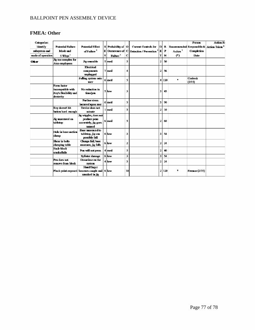
BALLPOINT PEN ASSEMBLY DEVICE
Page 77 of 78
FMEA: Other

BALLPOINT PEN ASSEMBLY DEVICE
Page 78 of 78
Appendix E: Electric Circuit Diagram
Figure E1. Electric Circuit Diagram for Pen Assembly Device