ballast water treatment, u.s. great lakes bulk carrier
TRANSCRIPT

Ballast Water Treatment, U.S. Great Lakes Bulk Carrier Engineering and Cost Study Volume I: Present Conditions Distribution Statement A: Approved for public release; distribution is unlimited.
November 2013
Report No. CG-D-12-13 (Volume I of II)

Ballast Water Treatment, U.S. Great Lakes Bulk Carrier Engineering and Cost Study Volume I: Present Conditions
UNCLAS//PUBLIC | CG-926 RDC | J. Waterhouse, et al. | Public November 2013
ii
N O T I C E
This document is disseminated under the sponsorship of the Department of Homeland Security in the interest of information exchange. The United States Government assumes no liability for its contents or use thereof. The United States Government does not endorse products or manufacturers. Trade or manufacturers’ names appear herein solely because they are considered essential to the object of this report. This report does not constitute a standard, specification, or regulation.
Timothy R. Girton Technical Director United States Coast Guard Research & Development Center 1 Chelsea Street New London, CT 06320

Ballast Water Treatment, U.S. Great Lakes Bulk Carrier Engineering and Cost Study Volume I: Present Conditions
UNCLAS//PUBLIC | CG-926 RDC | J. Waterhouse, et al. | Public November 2013
iii
Technical Report Documentation Page1. Report No.
CG‐D‐12‐13 2. Government Accession Number
3. Recipient’s Catalog No.
4. Title and Subtitle
Ballast Water Treatment, U.S. Great Lakes Bulk Carrier Engineering and Cost Study - Volume I: Present Conditions
5. Report Date
November 2013 6. Performing Organization Code
Project No. 410141 7. Author(s)
John Waterhouse, Reginald Wren; Mike Johnson; Nicholas Barczak; M. J. Lewandowski, E. David Tietje
8. Performing Organization Report No.
RDC UDI No. 1230
9. Performing Organization Name and Address
U.S. Coast Guard Research and Development Center 1 Chelsea Street New London, CT 06320
SAIC 23 Clara Drive, Suite 206 Mystic, CT 06355-1959 Elliott Bay Design Group 5305 Shilshole Ave NW, Ste 100 Seattle, WA 98107
10. Work Unit No. (TRAIS)
11. Contract or Grant No.
Contract HSCG32-10-D-R00021/ Task Order HSCG32-11-J-300010
12. Sponsoring Organization Name and Address
United States Environmental Protection Agency Great Lakes National Program Office 77 West Jackson Blvd. (G-17J) Chicago, IL 60604-3511 U.S. Department of Homeland Security Commandant (CG-OES-3) United States Coast Guard 2100 Second St. SW Washington, DC 20593-0001
13. Type of Report & Period Covered
Final 14. Sponsoring Agency Code
US EPA GLNPO Chicago, IL 60604-3511 Commandant (CG-OES-3) U.S. Coast Guard Headquarters Washington, DC 20593-0001
15. Supplementary Notes
The R&D Center’s technical point of contact is Mr. Marion J. Lewandowski, (860) 271-2692, e-mail: [email protected].
16. Abstract (MAXIMUM 200 WORDS)
The intent of this study is to investigate the design and ballast water management (BWM) practices of US flag vessels operating solely within the Great Lakes; assess the potential for these vessels to install and operate ballast water management systems to kill or remove living organisms; and develop generalized, installation design and cost estimations, including a land-based alternative to shipboard ballast water treatment. “Ballast Water Treatment, U.S. Great Lakes Bulk Carrier Engineering and Cost Study – Volume I: Present Conditions” identifies ballast water practices as related to trading patterns, including an analysis of ballast discharge information with respect to vessel size and type, using information from calendar year 2010. The study selects five vessels that best represent the “full range” of U. S. flag “Laker” trade (including voyage patterns and vessel types). In “Ballast Water Treatment - U.S. Great Lakes Bulk Carrier Engineering and Cost Study – Volume II: Analysis of On-Board Treatment Methods, Alternative Ballast Water Management Practices, and Implementation Costs,” we examine the costs to outfit and operate four of the five vessels with installed ballast water treatment systems, and also investigate cost associated with treating ballast water ashore. Importantly, this study does not assess the ability of any ballast water management system or practice to kill or remove organisms in ships’ ballast water.
17. Key Words 18. Distribution Statement
Ballast water Bulk carriers Great Lakes Lakers Treatment Technology
Distribution Statement A: Approved for public release; distribution is unlimited.
19. Security Class (This Report)
UNCLAS//PUBLIC 20. Security Class (This Page)
UNCLAS//PUBLIC 21. No of Pages
96 22. Price

Ballast Water Treatment, U.S. Great Lakes Bulk Carrier Engineering and Cost Study Volume I: Present Conditions
UNCLAS//PUBLIC | CG-926 RDC | J. Waterhouse, et al. | Public November 2013
iv
This page intentionally left blank.

Ballast Water Treatment, U.S. Great Lakes Bulk Carrier Engineering and Cost Study Volume I: Present Conditions
UNCLAS//PUBLIC | CG-926 RDC | J. Waterhouse, et al. | Public November 2013
v
ACKNOWLEDGEMENTS
The project team would like to gratefully acknowledge the following individuals and organizations for the assistance and support they provided in developing this report:
• The American Steam Ship Company, Williamsville, New York • Grand River Navigation Company, Avon Lake, Ohio • Interlake Steamship Company, Richfield, Ohio • Key Lakes, Inc., Duluth, Minnesota • Lake Carriers’ Association, Rocky River, Ohio • Van Enkevort Tug & Barge, Inc., Escanaba, Michigan

Ballast Water Treatment, U.S. Great Lakes Bulk Carrier Engineering and Cost Study Volume I: Present Conditions
UNCLAS//PUBLIC | CG-926 RDC | J. Waterhouse, et al. | Public November 2013
vi
This page intentionally left blank.

Ballast Water Treatment, U.S. Great Lakes Bulk Carrier Engineering and Cost Study Volume I: Present Conditions
UNCLAS//PUBLIC | CG-926 RDC | J. Waterhouse, et al. | Public November 2013
vii
EXECUTIVE SUMMARY
This study is an independent assessment from the Coast Guard R&D Center to the Coast Guard Office of Environmental Standards and the Great Lakes National Program Office of the Environmental Protection Agency. The overarching purpose of this R&D Center study is to provide knowledge to assist and inform project sponsors in policy development. The R&D Center does not set Coast Guard policy.
Mitigating and/or preventing the introduction and spread of invasive marine species throughout the Great Lakes system has been an ongoing concern for over 20 years. Multiple studies show that untreated ballast water discharged from seagoing vessels is a significant path for introducing and spreading invasive and/or non-native aquatic species into the region. Other studies theorize that ballast water operations by Lakers1 and other vessels also tend to spread invasive and non-native species throughout the Great Lakes system. Under the Non-indigenous Aquatic Nuisance Prevention and Control Act of 1990 (NANPCA), and as reauthorized and amended by the National Invasive Species Act of 1996 (NISA), the United States Coast Guard (USCG) is authorized (and actively engaged) in the rule-making process to help prevent the introduction and spread of non-indigenous marine species within the waters of the United States. Recent advances in Ballast Water Treatment (BWT) systems, along with continued international and regional attention on this (worldwide) problem, provide us with potential tools to combat this threat.
The purpose of this volume is to research, document, and understand the variables associated with ballast water transport by United States (U. S.) flag Lakers, including ballast water system design and ballast water management (BWM) practices. Based on this research, a second purpose is to identify five specific vessel/voyage combinations that represent the broad range of vessel/voyage patterns associated with ballast water movement throughout the Great Lakes system. The scope of this work does not include Canadian Lakers or other vessels (bulk carriers, tankers, or barges) that do not trade exclusively on the Great Lakes.
This volume focuses on commodity trade routes and ballast water transport data, which are available through public domain (Lake Carriers' Association website; National Ballast Information Clearinghouse website; USCG vessel database website; Great Lakes and Seaway Shipping website; Great Lakes Information Network website; American Bureau of Shipping (ABS) vessel database (ABS Record) website; and American Steamship Company website) with additional background from two technical reports (McCormick, August 1996; Cangelosi & Mays, May 1996). Detailed vessel information was provided by the vessel owners/operators. Especially helpful to this effort is the information available through the National Ballast Information Clearinghouse (NBIC) website, which provides statistical data on the intake and discharge of ballast water transport throughout the Great Lakes region. Due to the extremely large amount of data available, this research effort focused only on ballast water data from the year 2010 and records associated only with U.S. flag vessels. The analysis provides a clear picture of the magnitude and geographic extent of ballast water transport and the diversity of associated routes, ports, and U. S. flag
1
"Laker" is the common name for the large and uniquely designed and constructed dry bulk vessels (or carriers) used to transport bulk material commodities throughout the Great Lakes system. U. S. flag lakers usually only transport goods on the four upper Great Lakes and connecting channels, as most are limited by their size from transiting the Welland Canal. The primary commodities transported by the Lakers include iron ore pellets, coal, grain, limestone, cement, sand, and salt, and are described in more detail in Section 2 of this volume.

Ballast Water Treatment, U.S. Great Lakes Bulk Carrier Engineering and Cost Study Volume I: Present Conditions
UNCLAS//PUBLIC | CG-926 RDC | J. Waterhouse, et al. | Public November 2013
viii
vessels that travel the Great Lakes. Figure 1 through Figure 5 and Table 2 through Table 7 summarize this analysis.
The volume includes a detailed review of Laker trades, and differences among representative vessels – specifically with regard to ballast water systems and ballast water management (BWM) practices. The work selected five vessel/voyage combinations to represent the full range of contemporary U.S. Laker trade. The vessels selected were of various designs and constructed between 1952 and 2000. Four were “typical” Great Lakes self-unloading bulk carriers and the fifth was an articulated tug and barge (ATB.) The trade routes and ballast transport span a range from two ports (one cargo loading and one cargo discharge) to a combination of seven ports (cargo loading and discharge at multiple ports). The vessels and representative routes selected are:
1. Intermediate to Large Capacity 1000’ Laker with a basic route between West Lake Superior (cargo loading) and South Lake Michigan (cargo discharge). This trade route is for iron ore pellets.
2. Large Capacity 1000’ Laker with a basic trade route between West Lake Superior (cargo loading) and South Lake Huron (cargo discharge). This trade route is mainly coal.
3. Older, Small Capacity 700’ – 800’ Laker that operates among South Lake Michigan, Northwest Lake Huron, and West Lake Erie ports. This vessel carries a variety of commodities among multiple ports.
4. Newer, Intermediate Capacity 800’ – 900’ ATB that operates in North and South Lake Michigan, Northwest and South Lake Huron, and West Lake Erie. This vessel carries a variety of commodities among multiple ports.
5. Small Capacity, River Class 600’ – 700’ Laker that operates in North Lake Michigan, Northwest and South Lake Huron, and Lake Erie. This vessel carries a variety of commodities among multiple ports.

Ballast Water Treatment, U.S. Great Lakes Bulk Carrier Engineering and Cost Study Volume I: Present Conditions
UNCLAS//PUBLIC | CG-926 RDC | J. Waterhouse, et al. | Public November 2013
ix
TABLE OF CONTENTS
ACKNOWLEDGEMENTS .......................................................................................................................... v
EXECUTIVE SUMMARY ......................................................................................................................... vii
LIST OF FIGURES ...................................................................................................................................... xi
LIST OF TABLES ....................................................................................................................................... xii
LIST OF ACRONYMS .............................................................................................................................. xiii
CONVERSION TABLES ........................................................................................................................... xiv
1 INTRODUCTION .................................................................................................................................. 1
2 TRADE ROUTES ................................................................................................................................... 2
3 BALLAST WATER DATA ANALYSIS .............................................................................................. 7
4 VESSEL/VOYAGE SELECTION CRITERIA ................................................................................. 21 4.1 Vessel Selection .............................................................................................................................. 22 4.2 Voyage Selection ............................................................................................................................ 23
5 VESSEL/VOYAGE SELECTIONS AND DESCRIPTIONS ........................................................... 23
6 CONCLUSIONS ................................................................................................................................... 25
7 REFERENCES ..................................................................................................................................... 33
APPENDIX A INTERMEDIATE TO LARGE CAPACITY 1000' LAKER .................................... A-1
APPENDIX B LARGE CAPACITY 1000' LAKER ........................................................................... B-1
APPENDIX C OLDER, SMALL CAPACITY 700' – 800' LAKER .................................................. C-1
APPENDIX D NEWER, INTERMEDIATE CAPACITY 800' – 900' LAKER ................................ D-1
APPENDIX E SMALL CAPACITY, RIVER CLASS 600’ – 700’ LAKER ..................................... E-1

Ballast Water Treatment, U.S. Great Lakes Bulk Carrier Engineering and Cost Study Volume I: Present Conditions
UNCLAS//PUBLIC | CG-926 RDC | J. Waterhouse, et al. | Public November 2013
x
This page intentionally left blank.

Ballast Water Treatment, U.S. Great Lakes Bulk Carrier Engineering and Cost Study Volume I: Present Conditions
UNCLAS//PUBLIC | CG-926 RDC | J. Waterhouse, et al. | Public November 2013
xi
LIST OF FIGURES
Figure 1. Iron ore pellets trade routes. ............................................................................................................ 3 Figure 2. Coal trade routes. ............................................................................................................................. 4 Figure 3. Limestone trade routes. ................................................................................................................... 5 Figure 4. Cement trade routes. ........................................................................................................................ 6 Figure 5. Great Lakes ballast water transport. ................................................................................................ 9 Figure 6. Ballast water hold time. ................................................................................................................. 15 Figure 7. Intermediate to large capacity 1000' Laker trade route. ................................................................ 26 Figure 8. Large capacity 1000' Laker trade route. ........................................................................................ 27 Figure 9. Older, small capacity 700' – 800' Laker trade route. ..................................................................... 28 Figure 10. Newer, intermediate capacity 800' − 900' Laker trade route. ...................................................... 29 Figure 11. Small capacity, river class 600' − 700' Laker trade route. ........................................................... 30 Figure A-1. Intermediate to large capacity 1000' Laker: photo. ................................................................ A-4 Figure A-2. Intermediate to large capacity 1000' Laker: general arrangement. ........................................ A-5 Figure A-3. Intermediate to large capacity 1000' Laker: engine room arrangement. ................................ A-6 Figure A-4. Intermediate to large capacity 1000' Laker: ballast diagram. ................................................ A-7 Figure B-1. Large capacity 1000' Laker: photo. ........................................................................................ B-5 Figure B-2. Large capacity 1000' Laker: general arrangement.................................................................. B-7 Figure B-3. Large capacity 1000' Laker: engine room arrangement. ........................................................ B-8 Figure B-4. Large capacity 1000' Laker: ballast water diagram. ............................................................... B-9 Figure C-1. Older, small capacity 700' - 800' Laker: photo. ...................................................................... C-5 Figure C-2. Older, small capacity 700' - 800' Laker: general arrangement. .............................................. C-7 Figure C-3. Older, small capacity 700' - 800' Laker: engine room arrangement. ...................................... C-8 Figure C-4. Older, small capacity 700' - 800' Laker: ballast diagram. ...................................................... C-9 Figure D-1. Newer, intermediate capacity 800' – 900' Laker: photo. ........................................................ D-8 Figure D-2. Newer, intermediate capacity 800' – 900' Laker: general arrangement. ................................ D-9 Figure D-3. Newer, intermediate capacity 800' – 900' Laker: engine room arrangement. ...................... D-10 Figure D-4. Newer, intermediate capacity 800' – 900' Laker: ballast water diagram. ............................. D-11 Figure E-1. Small capacity, river class 600’ – 700’ Laker: photo. ............................................................. E-4 Figure E-2. Small capacity, river class 600’ – 700’ Laker: general arrangement. ..................................... E-5 Figure E-3. Small capacity, river class 600’ – 700’ Laker: engine room arrangement. ............................. E-6 Figure E-4. Small capacity, river class 600’ – 700’ Laker: ballast diagram. .............................................. E-7

Ballast Water Treatment, U.S. Great Lakes Bulk Carrier Engineering and Cost Study Volume I: Present Conditions
UNCLAS//PUBLIC | CG-926 RDC | J. Waterhouse, et al. | Public November 2013
xii
LIST OF TABLES
Table 1. Commodities trade, year 2010. ......................................................................................................... 2 Table 2. Great Lakes ports by region*. ........................................................................................................... 8 Table 3. Ballast discharge volumes by region with top 5 discharging vessels. ............................................ 11 Table 4. Ballast discharge by arrival port. .................................................................................................... 12 Table 5. Ballast intake by departure port. ..................................................................................................... 13 Table 6. Vessel information for the top 25 vessels by volume of ballast water discharged for 2010. ......... 17 Table 7. Count of region-to-region (and intra-region) trips for the top 25 vessels. ...................................... 19 Table 8. Vessel/voyage selections. ............................................................................................................... 24 Table A-1. Intermediate to large capacity 1000' Laker: principal characteristics. .................................... A-1 Table A-2. Intermediate to large capacity 1000' Laker: ballast tank capacities (estimated). .................... A-2 Table A-3. Intermediate to large capacity 1000' Laker: ballast pumping capacities. ................................ A-3 Table A-4. Intermediate to large capacity 1000' Laker: operational ballast conditions (sample). ............ A-3 Table B-1. Large capacity 1000' Laker: principal characteristics. ............................................................. B-1 Table B-2. Large capacity 1000' Laker: ballast tank capacities................................................................. B-2 Table B-3. Large capacity 1000' Laker: ballast pumping capacities. ........................................................ B-2 Table B-4. Large capacity 1000' Laker: operational ballast conditions (samples). ................................... B-3 Table B-5. Large capacity 1000’ Laker: summary of estimated electrical load. ........................................ B-4 Table C-1. Older, small capacity 700' - 800' Laker: principal characteristics. .......................................... C-1 Table C-2. Older, small capacity 700' - 800' Laker: ballast tank capacities. ............................................. C-2 Table C-3. Older, small capacity 700' - 800' Laker: ballast pumping capacities. ...................................... C-3 Table C-4. Older, small capacity 700' - 800' Laker: operational ballast conditions. ................................. C-3 Table C-5. Older, small capacity 700' - 800' Laker: summary electrical of load. ..................................... C-4 Table D-1. Newer, intermediate capacity 800' – 900' Laker: principal characteristics. ............................ D-1 Table D-2. Newer, intermediate capacity 800' – 900' Laker: ballast tank capacities. ............................... D-2 Table D-3. Newer, intermediate capacity 800' – 900' Laker: ballast pumping capacities. ........................ D-3 Table D-4. Newer, intermediate capacity 800' – 900' Laker: operational ballast conditions. ................... D-3 Table D-5. Newer, intermediate capacity 800' - 900' Laker: summary of electrical load. ........................ D-4 Table E-1. Small capacity, river class 600’ – 700’ Laker: principal characteristics. ................................. E-1 Table E-2. Small capacity, river class 600’ – 700’ Laker: ballast tank capacities. .................................... E-2 Table E-3. Small capacity, river class 600’ – 700’ Laker: ballast pumping capacities. ............................. E-3 Table E-4. Small capacity, river class 600’ – 700’ Laker: operational ballast conditions. ........................ E-3

Ballast Water Treatment, U.S. Great Lakes Bulk Carrier Engineering and Cost Study Volume I: Present Conditions
UNCLAS//PUBLIC | CG-926 RDC | J. Waterhouse, et al. | Public November 2013
xiii
LIST OF ACRONYMS
ABS American Bureau of Shipping AR Arrival region ATB Articulated Tug and Barge BWM Ballast Water Management BWT Ballast Water Treatment EBDG Elliott Bay Design Group ft Foot IMO International Maritime Organization ITB Integrated tug and barge LCA Lakes Carriers Association lt Long ton (2240 pounds) mt Metric ton (2205 pounds) NANPCA Non-indigenous Aquatic Nuisance Prevention and Control Act [of 1990] NBIC National Ballast Information Clearinghouse NISA National Invasive Species Act [of 1996] nt Net tons (2000 pounds) RDC Research & Development Center SAIC Science Applications International Corporation SERC Smithsonian Environmental Research Center TDH Total dynamic head U.S. United States USCG United States Coast Guard

Ballast Water Treatment, U.S. Great Lakes Bulk Carrier Engineering and Cost Study Volume I: Present Conditions
UNCLAS//PUBLIC | CG-926 RDC | J. Waterhouse, et al. | Public November 2013
xiv
CONVERSION TABLES
Name of Unit Symbol Conversion Length meter m foot Ft or ‘ = 0.3048 m Area square foot ft2 = 0.0929 m2
Volume liter L
cubic foot ft3 = 0.0283 m3 = 28.3168 L
gallon gal
= 3.7854 ·10-3 m3
= 3.7854 L = 0.1337 ft3 = 3.7854 · 10-3 mt (ρfw = 62.2 lb/ft3)
Weight kilogram kg
long ton lt = 1016 kg = 2240 lb
metric ton mt = 1000 kg = 2204.6 lb
net tons nt = 907.1847 kg = 2,000 pounds
pounds lb = 0.4536 kg Flow Rate
gallons per minute gpm = 6.3090 · 10-5 m3/sec = 0.2271 mt/hr
Power kilowatt kW Horsepower hp 0.745 kW

Ballast Water Treatment, U.S. Great Lakes Bulk Carrier Engineering and Cost Study Volume I: Present Conditions
UNCLAS//PUBLIC | CG-926 RDC | J. Waterhouse, et al. | Public November 2013
1
1 INTRODUCTION
The primary goal of this part of the study is to identify and document the broad range of differences among trade routes and vessels, specifically with regard to ballast water systems and ballast water management (BWM) practices of vessels engaged in the United States (U.S.) flag Great Lakes commodities trades. Towards this end, the work identifies five specific vessel/voyage combinations that represent the broad range of vessel/voyage variables associated with transporting ballast water throughout the Great Lakes system.
Section 2 provides a brief perspective on the commodities trades and an overview of the most travelled trade routes of U.S. flag vessels on the Great Lakes. The trade route charts represent a high-level look at the general areas and ports where ballast water is taken into the vessels and where it is discharged.
Section 3 develops and presents an in-depth analysis of the ballast water volumes transported by specific vessels on specific routes. From this analysis, we determine the terminus points of the movement of ballast water, the extent and magnitude of ballast water transport, and the time durations associated with transiting these routes; thus we derive the amount of time ballast water is contained aboard each ship, for each route.
In Section 4, data presented in Sections 2 and 3 are used with defined vessel selection criteria to identify five specific vessel/voyage combinations. Collectively, these five selected vessel/voyage combinations represent the full range of variables associated with contemporary U.S. Laker trade. These variables are grouped into two separate categories:
1. Variables among vessels 2. Variables among trade routes
There are significant differences in the construction, size, propulsion configurations, electrical systems and capabilities, cargo off-loading equipment, and other design aspects of the vessels engaged in trade on the Great Lakes. These differences have definite impacts upon the economic and technical challenges associated with operating and maintaining the vessels, as well as implementing capital improvements onboard the vessels. Similarly, the difference among trade routes – primarily dominated by the different lengths and transit durations of the routes themselves – also has significant influence on the technical efficacy and costs of various Ballast Water Treatment (BWT) technologies and BWM practices.
Section 5 contains written descriptions and graphic representations of the five selected vessel/voyage combinations.
Appendix A through Appendix E consist of the selected five vessels' principal characteristics, drawings, and other technical documentation.

Ballast Water Treatment, U.S. Great Lakes Bulk Carrier Engineering and Cost Study Volume I: Present Conditions
UNCLAS//PUBLIC | CG-926 RDC | J. Waterhouse, et al. | Public November 2013
2
2 TRADE ROUTES
There are a number of specific bulk commodities, along with other general cargos, traded and transported on the Great Lakes system. The greatest tonnage of dry bulk cargo transported on the Great Lakes system is transported by U.S. flag vessels among U.S. ports. This U.S.-to-U.S. port shipping industry trade is a segment of what is commonly referred to as the "Jones Act Trade," and only U.S. flag vessels are allowed to participate in these U.S. coastal trades. Almost all the U.S. flag carriers engaged in this trade belong to the Lakes Carriers Association (LCA). LCA is a marine industry trade organization whose membership includes 17 companies operating over 55 U.S. flag vessels. These vessels range in length from roughly 494 ft to the largest of the Lakers topping out around 1013 ft. In years past, total dry bulk cargo movement by LCA fleet vessels and other U.S. flag Laker operators has exceeded more than 125 million net tons (nt) in a single year. (Note: For purposes of this report and in accordance with LCA's commodities trade information, cargo amounts are provided in net tons (nt).)
The shipping companies that are members of the LCA transported 88.7 million nt of dry bulk commodities in 2010 (Lake Carriers' Association, 2010). The seven major commodities and the net tons transported are listed in Table 1.
Table 1. Commodities trade, year 2010.
Iron Ore Pellets: 42,028,418 ntCoal (total): 21,539,866 ntLimestone: 20,410,266 ntCement: 2,782,259 ntSalt: 1,391,239 ntSand: 225,593 ntGrain: 306,872 nt
Figure 1 through Figure 4 generally depict the four major commodity trade routes. These routes do not include U.S.-Canada trade, and for the purposes of this work, assume that a vessel does not “back-haul” a cargo en route to a load port (or a nearby port). A full, detailed discussion of Great Lakes trading would include the instances where cargo discharge and load ports are nearby each other. However, when viewed in terms of total ballast water movement, these short trips account for only a small percentage of the total.
The trading routes for the iron ore pellets are shown in Figure 1. The primary trade route for iron is from western Lake Superior, Marquette (Presque Isle), and Escanaba to the lower lakes.
The trade routes for coal are shown in Figure 2. “Western” coal moves from Superior, WI east and south, and from Chicago northward, while “Eastern” coal moves from Lake Erie throughout the lakes.
The trading routes for limestone are shown in Figure 3. The primary trade route for limestone is from the Northern section of Lake Huron and Lake Michigan to the other lakes. There is one location in western Lake Erie that also provides limestone.
The trading routes for cement are shown in Figure 4. There are two U.S. cement plants (Charlevoix and Alpena) that supply all U.S. ports on the lakes.

Ballast Water Treatment, U.S. Great Lakes Bulk Carrier Engineering and Cost Study Volume I: Present Conditions
UNCLAS//PUBLIC | CG-926 RDC | J. Waterhouse, et al. | Public November 2013
3
Figure 1. Iron ore pellets trade routes.

Ballast Water Treatment, U.S. Great Lakes Bulk Carrier Engineering and Cost Study Volume I: Present Conditions
UNCLAS//PUBLIC | CG-926 RDC | J. Waterhouse, et al. | Public November 2013
4
Figure 2. Coal trade routes.

Ballast Water Treatment, U.S. Great Lakes Bulk Carrier Engineering and Cost Study Volume I: Present Conditions
UNCLAS//PUBLIC | CG-926 RDC | J. Waterhouse, et al. | Public November 2013
5
Figure 3. Limestone trade routes.

Ballast Water Treatment, U.S. Great Lakes Bulk Carrier Engineering and Cost Study Volume I: Present Conditions
UNCLAS//PUBLIC | CG-926 RDC | J. Waterhouse, et al. | Public November 2013
6
Figure 4. Cement trade routes.

Ballast Water Treatment, U.S. Great Lakes Bulk Carrier Engineering and Cost Study Volume I: Present Conditions
UNCLAS//PUBLIC | CG-926 RDC | J. Waterhouse, et al. | Public November 2013
7
3 BALLAST WATER DATA ANALYSIS
Taking on, transporting, and then discharging ballast water is an integral design and operating feature of practically all commercial ships that operate on the Great Lakes. During cargo unloading operations and/or when empty, ships take on ballast water to maintain draft and stability; submerge the propeller, rudders, and bow thrusters; and maintain or minimize stress loads on the hull. Vessels may only load some of their ballast tanks at the cargo discharge port because transporting ballast water from port to port increases operational costs due to increased fuel consumption. Vessels routinely take on additional ballast en route during transit. This operation is attributable to events such as bad weather, but ballast is sometimes taken on or discharged in multiple locations, for instance if a vessel is either loading at multiple ports, or splitting discharge at multiple ports.
Ultimately, the amount, weight, and distribution of cargo onboard determine ballast loads and their distribution within the vessel. For the largest of the Great Lakes vessels, loading and un-loading operations typically require 8 to 10 hours, and the quantity of ballast water discharged/taken in during these operations ranges between approximately 10 and 15 million gallons (38,000 to 57,000 metric tons (mt)).
The National Ballast Information Clearinghouse (NBIC) is a joint program of the Smithsonian Environmental Research Center (SERC) and the United States Coast Guard (USCG) chartered to collect, analyze, and interpret data on the ballast water management practices of commercial ships that operate in the waters of the United States. The NBIC was established in 1997 at the direction of the 1996 National Invasive Species Act (NISA). A principal aim of the NBIC is to quantify the amounts and origins of ballast water discharged in U.S. coastal systems, and to determine the degree to which such water has undergone open-ocean exchange or alternative treatments designed to reduce the likelihood of ballast-mediated invasions by exotic species.
The purpose of the data analysis in this volume is to develop criteria to cover the full-range of the U.S. Laker trade to reflect movement of ballast water. Specifically, the analysis must lead to vessel types and trade routes (vessel/voyage pairs) that represent this “full range.” The work uses NBIC data for the year 2010 and U.S. flag vessels to review the transport of ballast water in the Great Lakes system. In 2010, the total ballast water discharge by ALL vessels in U.S. Great Lakes ports was more than 52 million mt. In 2010, U.S. flag vessels discharged approximately 42 million mt of ballast water in U.S. Great Lakes ports (approximately 80% of the total). We extracted records that represented the vast majority of ballast water discharged at U.S. ports. Our analysis accounts for more than 95% of the ballast water discharged by the U.S. fleet. The analysis provides an understanding of the volumes and geographic extent of ballast water transport by U.S. flag Lakers. The information provides comparisons among specific vessels, routes, ports, and regions of the Great Lakes.
This volume divides the Great Lakes into regions to better understand ballast water transport based on major trade routes. The trade patterns take into account, but do not specifically align with voyage characterizations by the Lake Carriers Association (2010) or Rup, Bailey,et al. (2010). The ports for each region are listed in Table 2 and are graphically depicted in Figure 5 below. We included St. Clair River and Saginaw Bay and River ports in the South Huron region, while Detroit River and River Rouge ports appear in the West Erie region.

Ballast Water Treatment, U.S. Great Lakes Bulk Carrier Engineering and Cost Study Volume I: Present Conditions
UNCLAS//PUBLIC | CG-926 RDC | J. Waterhouse, et al. | Public November 2013
8
Table 2. Great Lakes ports by region*.
West Superior Region A
East Superior Region B
North Lake Michigan
Region C
South Lake Michigan
Region D
Northwest HuronRegion E
South Huron Region F
West Erie Region G
East Erie Region H
Ashland, WI Marquette, MI Brevort, MI Buffington, IN Alpena, MI Bay City, MI Cleveland, OH Ashtabula, OH Duluth, MN Munising, MI Charlevoix, MI Burns Harbor, IN Calcite, MI Carrollton, MI Dearborn, MI Buffalo, NY Hancock, MI Presque Isle
(UP), MI Escanaba, MI Calumet, IL Cedarville, MI Essexville, MI Detroit, MI Conneaut, OH
Ontonagon, MI Sault Ste. Marie, MI
Frankfort, MI Chicago, IL Cheboygan, MI Harbor Beach, MI
Ecorse, MI Dunkirk, NY
Silver Bay, MN Gladstone, MI Ferrysburg, MI Drummond Island, MI
Marine City, MI
Fairport Harbor, OH
Erie, PA
Superior, WI Green Bay, WI Gary, IN Mackinac Island, MI
Marysville, MI Huron, OH Tonawanda, NY
Taconite Harbor, MN Ludington, MI Grand Haven, MI Port Dolomite, MI Port Gypsum, MI
Kellys Island, OH
Two Harbors, MN Manistee, MI Holland, MI Presque Isle, MI Port Huron, MI Lorain, OH Manitowoc, WI Indiana Harbor, IN Stoneport, MI Saginaw, MI Marblehead,
OH
Marinette, WI Milwaukee, WI Saint Clair, MI Monroe, MI Menominee, MI Muskegon Harbor,
MI Tawas City, MI River Rouge,
MI
Port Inland, MI Oak Creek, WI Zilwaukee, MI Sandusky, OH Sturgeon Bay, WI Port Washington,
WI Toledo, OH
Traverse City, MI Racine Harbor, WI Trenton, MI Saint Joseph, MI Wyandotte,
MI
South Chicago, IL Waukegan, IL Whiting, IN *Note: Multiple names may appear for the same “port,” based on NBIC entry or common name.

Ballast Water Treatment, U.S. Great Lakes Bulk Carrier Engineering and Cost Study Volume I: Present Conditions
UNCLAS//PUBLIC | CG-926 RDC | J. Waterhouse, et al. | Public November 2013
9
Figure 5. Great Lakes ballast water transport.

Ballast Water Treatment, U.S. Great Lakes Bulk Carrier Engineering and Cost Study Volume I: Present Conditions
UNCLAS//PUBLIC | CG-926 RDC | J. Waterhouse, et al. | Public November 2013
10
Table 3 summarizes the quantity of ballast water transferred among the regions described in Table 2 and Figure 5 by U.S. flag vessels. Ballast water quantities are in metric tons. The top 23 routes are listed, ranked by the quantities of ballast water transported by U.S. flag vessels from their “Departure Region” (ballast uptake) to their Arrival Region (ballast water discharge). The five vessels that transport the most ballast water are listed for each region. The five vessels listed for each region-transit pair (from highest ballast discharge to least ballast discharge) do not account for 100% of the “all U.S. vessel total” shown at the bottom of Table 3. They account for a large majority of those regional transit values and percentages, but other vessels not listed make up some smaller percentage of the listed values. Graphical overviews of the general routes are shown in Figure 5. Each numbered route in Figure 5 corresponds to the rank of the route listed in Table 3.
Table 3 yields two significant pieces of information: (1) In 2010, more than half of the total ballast water discharged by U.S. vessels into the Great Lakes was discharged into western Lake Superior ports by 13 vessels, all but one being 1000-foot, all transiting from lower-lake ports. (2) All sizes of Lakers are responsible for intra-regional movement of ballast, even 1000-foot Lakers.
The individual port locations with high ballast water discharge may affect vessel/voyage selection. The ports with the highest ballast water discharge are listed in Table 4. More than 50 percent of the ballast water discharged occurs at Superior and Two Harbors, indicating that transport of iron ore pellets and Western coal, and the subsequent return to loadport in a ballast condition, results in the majority of ballast water transport by U.S. Lakers on the Great Lakes.

Ballast Water Treatment, U.S. Great Lakes Bulk Carrier Engineering and Cost Study Volume I: Present Conditions
UNCLAS//PUBLIC | CG-926 RDC | J. Waterhouse, et al. | Public November 2013
11
Table 3. Ballast discharge volumes by region with top 5 discharging vessels (for each regional transport of ballast water).
Rank Departure Region
Arrival Region (AR)
Total Annual Coastwise Ballast
Transported (mt)
Vessels with Greatest Discharge
AR TotalDischarge
Percentof Total 1st 2nd 3rd 4th 5th
1 S Lake Michigan W Superior 7,899,425 18.6% Edgar B. Speer Burns Harbor Stewart J. Cort Edwin H. Gott American Spirit 2 West Erie W Superior 6,739,416 15.9% Paul R. Tregurtha American Integrity Presque Isle Walter J. McCarthy Jr. Edwin H. Gott 3 S Huron W Superior 4,012,489 7.9% Indiana Harbor Paul R. Tregurtha American Century James R. Barker American Integrity 4 E Erie W Superior 3,984,870 9.4% American Century Edgar B. Speer Edwin H. Gott Roger Blough Presque Isle 5 West Erie NW Huron 2,208,294 5.2% Pathfinder H. Lee White John J. Boland Philip R. Clarke Sam Laud 6 S Lake Michigan N Lake Michigan 2,035,119 4.8% Joseph L. Block Great Lakes Trader Wilfred Sykes St. Marys Challenger Burns Harbor
7* West Erie West Erie 1,990,617 4.7% Pathfinder McKee Sons H. Lee White Calumet American Republic 8 S Lake Michigan NW Huron 1,298,398 3.1% Cason J. Callaway Philip R. Clarke John G. Munson Arthur M. Anderson Joseph H. Thompson 9 N Lake Michigan NW Huron 1,230,925 2.9% Lewis J. Kuber John G. Munson Cason J. Callaway Philip R. Clarke Innovation
10* W Superior W Superior 1,206,915 2.8% Philip R. Clarke John G. Munson James R. Barker American Century American Integrity 11 E Superior W Superior 1,155,024 2.7% Mesabi Miner James R. Barker Great Lakes Trader Herbert C. Jackson Manitowoc 12* N Lake Michigan N Lake Michigan 1,101,969 2.6% Lewis J. Kuber Joseph L. Block Wilfred Sykes St. Marys Challenger American Mariner 13 E Erie NW Huron 1,011,571 2.4% Great Lakes Trader Joseph H. Thompson James L Kuber John G. Munson American Mariner 14 West Erie E Superior 903,004 2.1% Kaye E. Barker Herbert C. Jackson Charles M. Beeghly Lee A. Tregurtha Pathfinder 15 E Erie West Erie 843,583 2.0% John J. Boland Manistee James L Kuber American Mariner H. Lee White 16 N Lake Michigan W Superior 831,467 2.0% American Integrity Walter J. McCarthy Jr. St. Clair John J. Boland Edwin H. Gott 17 S Huron NW Huron 904,220 1.4% Lewis J Kuber Calumet Manitowoc McKee Sons Joseph H. Thompson 18* S Lake Michigan S Lake Michigan 328,406 0.8% Manitowoc Cason J. Callaway Philip R. Clarke Arthur M. Anderson Manistee 19 N Lake Michigan S Lake Michigan 312,291 0.7% Calumet Manitowoc Manistee McKee Sons Endeavour 20* E Superior E Superior 247,493 0.6% Manitowoc Calumet Kaye E. Barker Lee A. Tregurtha Herbert C. Jackson 21* NW Huron NW Huron 154,909 0.4% Calumet Sam Laud Manitowoc Lewis J Kuber Manistee 22 West Erie N Lake Michigan 153,486 0.4% American Spirit Edwin H. Gott Mesabi Miner Herbert C. Jackson Lewis J Kuber 23 E Superior NW Huron 145,524 0.3% McKee Sons Manitowoc Pathfinder Calumet Alpena Total shown: 40,699,415 mt Total, all U.S. Vsls: 42,508,108 mt
% ballast moved by top 5 vsls: 95.7%
*These are intra-lake routes and not shown in Figure 5

Ballast Water Treatment, U.S. Great Lakes Bulk Carrier Engineering and Cost Study Volume I: Present Conditions
UNCLAS//PUBLIC | CG-926 RDC | J. Waterhouse, et al. | Public November 2013
12
Table 4. Ballast discharge by arrival port.
Rank Arrival Port Ballast Discharged (mt) % of Total
1 Superior 13,264,306 31.5 2 Two Harbors 8,092,120 19.2 3 Silver Bay 2,584,280 6.1 4 Duluth 2,008,944 4.8 5 Calcite 1,926,582 4.6 6 Port Inland 1,805,522 4.3 7 Marquette 1,600,102 3.8 8 Presque Isle 1,414,239 3.4 9 Stoneport 1,325,849 3.2 10 Marblehead 1,111,806 2.6 11 Escanaba 1,071,847 2.5 12 Toledo (USA, OH) 1,003,928 2.4 13 Port Dolomite 908,993 2.2 14 Alpena 876,457 2.1 15 Sandusky 569,505 1.4 16 Chicago 408,728 1.0 17 Drummond Island 397,421 0.9 18 Cleveland 300,483 0.7 19 Charlevoix 280,624 0.7 20 Sturgeon Bay 267,003 0.6 21 Cedarville 249,445 0.6 22 South Chicago 193,193 0.5 23 Ashtabula 166,512 0.4 24 Brevort 90,331 0.2 25 Burns Harbor 62,653 0.1 26 Whiting 48,436 0.1 27 Detroit 24,413 0.1 Totals (mt): 42,053,722 100.00
Table 5 lists the location of the ports where ballast water is taken on; it includes Canadian ports which are part of the U.S. flag vessel routes. Fifty percent of the ballast water taken on comes from seven ports, all in the southern portions of the Great Lakes.

Ballast Water Treatment, U.S. Great Lakes Bulk Carrier Engineering and Cost Study Volume I: Present Conditions
UNCLAS//PUBLIC | CG-926 RDC | J. Waterhouse, et al. | Public November 2013
13
Table 5. Ballast intake by departure port.
Rank Source Port Country Ballast Intake (mt) % of Total
1 Gary USA 4,534,821 10.8 2 Indiana Harbor USA 3,742,141 8.9 3 Saint Clair USA 3,313,204 7.9 4 Monroe USA 3,119,239 7.4 5 Cleveland USA 2,662,340 6.3 6 Burns Harbor USA 2,487,640 5.9 7 Detroit USA 2,283,156 5.4 8 Conneaut USA 1,810,050 4.3 9 Nanticoke Canada 1,794,733 4.3 10 Ashtabula USA 1,511,532 3.6 11 Ecorse USA 1,509,867 3.6 12 Marquette USA 1,091,068 2.6 13 Green Bay USA 846,869 2.0 14 River Rouge USA 837,103 2.0 15 Essexville USA 733,378 1.7 16 Toledo (USA, OH) USA 709,398 1.7 17 Muskegon USA 691,327 1.6 18 Duluth USA 664,908 1.6 19 Milwaukee USA 663,617 1.6 20 Buffington USA 461,467 1.1 21 Sault Ste. Marie Canada 389,307 0.9 22 Superior USA 387,075 0.9 23 Buffalo USA 352,368 0.8 24 Erie USA 304,388 0.7 25 Saginaw USA 294,644 0.7 26 Huron USA 283,021 0.7 27 Sturgeon Bay USA 278,322 0.7 28 Bay City USA 267,960 0.6 29 Dearborn (USA, MI) USA 264,638 0.6 30 Escanaba USA 260,130 0.6 31 Fairport (USA, OH) USA 249,517 0.6 32 Grand Haven USA 235,460 0.6 33 Silver Bay USA 187,074 0.4 34 Manistee USA 184,763 0.4 35 Alpena USA 176,459 0.4 36 Lorain USA 174,275 0.4 37 Marine City USA 173,683 0.4 38 Chicago USA 168,725 0.4 39 Saint Joseph USA 164,517 0.4 40 Taconite Harbor USA 159,447 0.4 41 Marysville USA 147,896 0.4 42 Port Inland USA 121,621 0.3

Ballast Water Treatment, U.S. Great Lakes Bulk Carrier Engineering and Cost Study Volume I: Present Conditions
UNCLAS//PUBLIC | CG-926 RDC | J. Waterhouse, et al. | Public November 2013
14
Table 5. Ballast intake by departure port (continued).
Rank Source Port Country Ballast Intake (mt) % of Total
43 Windsor Canada 114,332 0.3 44 Waukegan USA 103,813 0.2 45 Harbor Beach USA 92,478 0.2 46 Presque Isle USA 83,813 0.2 47 Charlevoix USA 77,855 0.2 48 Holland USA 68,324 0.2 49 Kingsville Canada 64,779 0.2 50 Manitowoc USA 60,749 0.1 51 Whitefish Falls, Ontario Canada 58,640 0.1 52 Wyandotte USA 53,482 0.1 53 Port Dolomite USA 47,956 0.1 54 Thorold Canada 47,760 0.1 55 Sault Ste. Marie USA 47,671 0.1 56 Sarnia Canada 40,130 0.1 57 Munising USA 34,583 0.1 58 Ferrysburg USA 32,093 0.1 59 Trenton (USA, MI) USA 30,507 0.1 60 Hamilton (Canada) Canada 25,955 0.1 61 Meldrum Bay Canada 25,769 0.1 62 South Chicago USA 25,230 0.1 63 Menominee USA 24,853 0.1 64 Heron Bay Canada 23,742 0.1 65 Milwaukee USA 19,985 <0.1 66 Montreal Canada 19,949 <0.1 67 Gladstone (USA, MI) USA 17,386 <0.1 68 Fairport Harbor USA 16,983 <0.1 69 Toronto Canada 16,641 <0.1 70 Ludington USA 16,322 <0.1 71 Cedarville USA 11,131 <0.1 72 Sandusky USA 11,127 <0.1 73 Calumet USA 10,789 <0.1 74 Carrollton USA 10,499 <0.1 75 Whitefish River Canada 7,742 <0.1 76 Prescott Canada 5,547 <0.1 77 Port Colborne Canada 5,547 <0.1 78 Fisher Harbor (Canada) Canada 5,547 <0.1 79 Marblehead USA 304 <0.1 80 Tracy Canada 268 <0.1 81 Whiting USA 268 <0.1 82 Rochester (USA, NY) USA 25 <0.1 Ballast Water Total (mt): 42,053,722 100.0

Ballast Water Treatment, U.S. Great Lakes Bulk Carrier Engineering and Cost Study Volume I: Present Conditions
UNCLAS//PUBLIC | CG-926 RDC | J. Waterhouse, et al. | Public November 2013
15
Figure 6 shows the results of further analysis of ballast uptake and discharge records. Figure 6 shows ballast water hold time for the percentage of ballast discharged, for the fleet as a whole, as well as for five, representative-type vessels.
Figure 6. Ballast water hold time.
The results show that discharges of the bulk of ballast water transported throughout the Great Lakes occurs between 24 hours and 96 hours after uptake. In 2010, only 6 percent of the ballast water discharged by the Laker fleet, as a whole, occurred less than 24 hours after uptake. Though the two representative-type 1000-foot vessels selected for this ballast water hold-time analysis did not indicate transits in ballast of less than 24 hours, Table 3 shows that 1000-foot vessels do make transits of less than 24 hours (W. Superior port to W. Superior port). This statistic generally indicates that BWT systems that allow safe discharge of treated ballast in 24 hours or less will have relatively low impact on current operations.
The results also show that there are considerable operational differences between vessels. For example, a BWT system which requires retention longer than 24 hours might be acceptable for installation on the “Large Capacity 1000’ Laker” that usually makes only long runs, whereas systems that require even short hold times might have an operational effect (i.e., delay) on vessels which routinely make shorter runs, such as the “Small Capacity, River Class 600’ – 700’ Laker.” Ultimately, the requirement will depend on a vessel’s specific operational profile. For the purposes of this engineering and cost study, in Volume II, only those BWT systems thought to allow discharge of ballast water within 24 hours of uptake are considered.

Ballast Water Treatment, U.S. Great Lakes Bulk Carrier Engineering and Cost Study Volume I: Present Conditions
UNCLAS//PUBLIC | CG-926 RDC | J. Waterhouse, et al. | Public November 2013
16
Early project-cost considerations limited the marine engineering efforts to picking only two systems, yielding a “one type fits all” approach.
Table 6 lists the top 25 vessels by amount of ballast water transported in 2010. Combined, these 25 U.S. flag vessels transported approximately 77 percent of the ballast water moved by U. S. vessels throughout the Great Lakes system. These 25 vessels represent a reasonably large cross-section of different vessel types, classes, sizes, and ballast system configurations and capabilities.
Table 6 includes additional information such as: general vessel type, International Maritime Organization (IMO) number, ballast system capacity, year and shipyard of build, cargo capacity, principal dimensions, ownership, and trade. This data was compiled from a variety of sources including public domain internet sites, the American Bureau of Shipping (ABS) Record Vessel Database, and the USCG Vessel Information Database, National Ballast Information Clearinghouse website; McCormick, 1996; Cangelosi & Mays, 1996; Lake Carriers’ Association website; Great Lakes and Seaway Shipping website; and the Great Lakes Information Network website.
Table 7 summarizes the total number of trips for a vessel by basic route, including intra and inter-region. This table shows the breadth of routes traveled by the various vessels. The shaded rows in Table 7 contain data from routes that are not included in the top 25 basic routes identified in Table 3.

Ballast Water Treatment, U.S. Great Lakes Bulk Carrier Engineering and Cost Study Volume I: Present Conditions
UNCLAS//PUBLIC | CG-926 RDC | J. Waterhouse, et al. | Public November 2013
17
Table 6. Vessel information for the top 25 vessels by volume of ballast water discharged for 2010.
Rank Vessel Name
Vessel Type
IMO Number
Total CoastwiseDischarge
(mt)
Ballast Capacity
(mt) Shipyard Year
Built
Capacity1
(long ton (lt))
Dimensions (ft) Owner/
Operator Trade L B D
1 Edgar B. Speer
Bulker 7625952 2,270,929 54,905 American Ship Bldg Co.
1980 73,700 1004.0 105.0 56.0 Great Lakes Fleet, Inc.
Iron Ore Pellets
2 James R. Barker
Bulker 7390260 1,874,938 44,308 American Ship Bldg Co.
1976 63,300 1004.0 105.0 50.0 Interlake Steamship Co.
Iron Ore Pellets, Coal
3 Paul R. Tregurtha
Bulker 7729057 1,803,112 51,816 Lorain, Ohio 1981 68,000 1013.5 105.0 56.0 Interlake Steamship Co.
Iron Ore Pellets, Coal
4 Edwin H. Gott
Bulker 7606061 1,796,276 62,294 Bay Shipbuilding Corp
1979 74,100 1004.0 105.0 52.0 Great Lakes Fleet, Inc.
Iron Ore Pellets
5 Mesabi Miner Bulker 7390272 1,780,563 44,389 American Ship Bldg. Corp.
1977 63,300 1004.0 105.0 50.0 Interlake Steamship Co.
Iron Ore Pellets, Coal
6 American Integrity
Bulker 7514696 1,659,621 62,143 Bay Shipbuilding Corp
1978 80,900 1000.0 105.0 56.0 American Steamship Co.
Iron Ore Pellets, Coal
7 Indiana Harbor
Bulker 7514701 1,653,444 62,143 Bay Shipbuilding Corp
1979 80,900 1000.0 105.0 56.0 American Steamship Co.
Iron Ore Pellets, Coal
8 Presque Isle ITB2 7303877 1,642,212 55,964 Halter Marine (Tug), Erie Marine (Barge)
1973 57,500 1000.0 104.6 46.5 GLF Great Lakes Corp
Iron Ore Pellets, Coal
9 Burns Harbor Bulker 7514713 1,624,552 62,143 Bay Shipbuilding Corp
1980 80,900 1000.0 105.0 56.0 American Steamship Co.
Iron Ore Pellets
10 American Century
Bulker 7923196 1,623,218 62,123 Bay Shipbuilding Corp
1981 80,900 1000.0 105.0 56.0 American Steamship Co.
Iron Ore Pellets
11 Walter J. McCarthy Jr.
Bulker 7514684 1,502,599 62,143 Bay Shipbuilding Corp
1977 80,900 1000.0 105.0 56.0 American Steamship Co.
Coal
12 Great Lakes Trader
ATB2 8635966 1,247,716 24,113 Halter Marine 2000 34,157 844.8 78.0 45.0 Van Enkevort Tug & Barge
Iron Ore Pellets, Coal, Limestone
13 American Spirit
Bulker 7423392 1,245,946 34,569 American Ship Building Co.
1978 62,400 1004.0 105.0 50.0 American Steamship Co.
Iron Ore Pellets
14 Roger Blough Bulker 7222138 1,136,012 35,637 American Ship Building Co.
1971 43,900 858.0 105.0 41.5 Great Lakes Fleet, Inc.
Iron Ore Pellets
15 Joseph L. Block
Bulker 7502320 1,050,473 21,578 Bay Shipbuilding 1976 37,200 728.0 78.0 45.0 Indiana. Harbor Steamship Co.
Iron Ore Pellets, Coal, Limestone
16 H. Lee White Bulker 7366362 1,023,398 22,031 Bay Shipbuilding Corp
1974 35,400 704.0 78.0 45.0 American Steamship Co.
Iron Ore Pellets, Coal, Limestone, Grain
17 Calumet Bulker 7329314 970,186 11,318 American Ship Building Co.
1973 19,650 630.0 68.0 36.9 Grand River Navigation
Iron Ore Pellets, Coal, Limestone
18 Pathfinder ATB 5166768 914,638 10,988 Great Lakes Engineering
1952 26,700 700.0 70.0 36.0 The Interlake Steamship Co.
Iron Ore Pellets, Coal, Limestone

Ballast Water Treatment, U.S. Great Lakes Bulk Carrier Engineering and Cost Study Volume I: Present Conditions
UNCLAS//PUBLIC | CG-926 RDC | J. Waterhouse, et al. | Public November 2013
18
Table 6. Vessel information for the top 25 vessels by volume of ballast water discharged for 2010 (Continued).
Rank Vessel Name
Vessel Type
IMO Number
Total CoastwiseDischarge
(mt)
Ballast Capacity
(mt) Shipyard Year
Built
Capacity1
(long ton (lt))
Dimensions (ft) Owner/
Operator Trade L B D
19 St. Clair Bulker 7403990 895,832 24,674 Bay Shipbuilding Corp
1976 44,800 770.0 92.0 52.0 American Steamship Co.
Iron Ore Pellets, Coal, Limestone
20 Stewart J. Cort
Bulker 7105495 894,600 39,590 Rust Eng. Co Erie Marine Division
1971 58,000 1000.0 105.0 49.0 Interlake Leasing III
Iron Ore Pellets
21 American Mariner
Bulker 7812567 877,702 23,426 Bay Shipbuilding Corp
1980 37,300 730.0 78.0 45.0 American Steamship Co.
Iron Ore Pellets, Coal, Limestone, Grain
22 Lewis J Kuber
ATB 5336351 818,922 16,546 Bethlehem-Sparrow Point
1952 22,300 617.0 70.0 37.0 Black Creek Shipping Co. Inc.
Iron Ore Pellets, Coal, Limestone
23 John J. Boland
Bulker 7318901 814,205 21,194 Bay Shipbuilding Corp
1973 34,000 667.0 78.0 43.0 American Steamship Co.
Iron Ore Pellets, Coal, Limestone, Grain
24 Philip R. Clarke
Bulker 5277062 762,480 17,245 American Ship Bldg Co.
1952 25,300 767.0 70.0 36.0 Great Lakes Fleet Inc.
Iron Ore Pellets, Coal, Limestone
25 John G. Munson
Bulker 5173670 745,272 11,932 Manitowoc Shipbuilding
1952 25,550 768.3 72.0 36.0 Great Lakes Fleet Inc.
Iron Ore Pellets, Coal, Limestone
Total: 25,077,550 Total for
U.S. Vessels: 42,508,108
Percent Captured:
76.8%
1Capacity refers to the maximum cargo carrying capacity of the vessel. This is also referred to as "Dead Weight Tonnage". 2ITB stands for "integrated tug and barge"; ATB stands for "articulated tug and barge." While similar in concept, the primary difference is the way the "tug" and "barge" connect, and the corresponding vessel characteristics while in a seaway. The tug of an ITB is connected rigidly to the barge and both hulls behave as if they are one large ship. The tug of an ATB on the other hand is allowed to pitch and heave somewhat separately from the barge through pinned connects into the barge hull.

Ballast Water Treatment, U.S. Great Lakes Bulk Carrier Engineering and Cost Study Volume I: Present Conditions
UNCLAS//PUBLIC | CG-926 RDC | J. Waterhouse, et al. | Public November 2013
19
Table 7. Count of region-to-region (and intra-region) trips for the top 25 vessels.
Regional Transits
Tot
al A
ll V
esse
ls
Am
eric
an C
entu
ry
Am
eric
an In
tegr
ity
Am
eric
an M
arin
er
Am
eric
an S
piri
t
Bur
ns H
arbo
r
Cal
umet
Edg
ar B
. Spe
er
Edw
in H
. Got
t
Gre
at L
akes
Tra
der
H. L
ee W
hite
Indi
ana
Har
bor
Jam
es R
. Bar
ker
John
G. M
unso
n
John
J. B
olan
d
Jose
ph L
. Blo
ck
Lew
is J
Kub
er
Mes
abi M
iner
Path
finde
r
Paul
R. T
regu
rtha
Phili
p R
. Cla
rke
Pres
que
Isle
Rog
er B
loug
h
St. C
lair
Stew
art J
. Cor
t W
alte
r J.
McC
arth
y Jr
.
S Lake Michigan To W Superior 116 2 1 1 21 1 1 14 5 4 2 1 1 1 1 12 19 10 18 1 West Erie To W Superior 113 1 2 10 13 1 9 1 1 8 12 3 1 28 21 1 1 E Erie To W Superior 93 21 1 4 2 10 11 1 4 8 1 1 9 13 3 4 West Erie To West Erie 94 3 15 11 6 4 4 50 1 S Huron To W Superior 48 12 1 1 1 14 2 2 1 12 1 1 West Erie To NW Huron 79 3 2 3 11 9 9 7 21 12 2 S Lake Michigan To N Lake Michigan 23 2 3 1 1 1 4 1 1 2 2 1 3 1 N Lake Michigan To NW Huron 49 2 7 13 1 1 13 4 8 SW Huron To NW Huron 50 21 28 1 W Superior To W Superior 47 2 2 1 2 1 1 3 3 14 1 1 1 14 1 N Lake Michigan To N Lake Michigan 40 5 6 1 1 3 5 17 1 1 E Superior To W Superior 16 3 1 11 1 S Lake Michigan To NW Huron 31 1 1 6 11 12 E Erie To NW Huron 16 3 1 2 8 1 1 E Erie To West Erie 28 5 6 2 4 3 7 1 N Lake Michigan To W Superior 25 7 2 1 1 1 1 2 3 1 1 3 1 1 SW Huron To W Superior 10 1 8 1 N Lake Michigan To S Lake Michigan 14 12 1 1 S Huron To NW Huron 14 7 1 6 NW Huron To NW Huron 2 1 1 S Lake Michigan To S Lake Michigan 9 2 1 2 1 3 West Erie To E Superior 7 1 6 E Superior To E Superior 7 7 West Erie To E Erie 5 2 2 1 West Erie To N Lake Michigan 4 1 1 1 1 E Superior To NW Huron 4 2 2 NW Huron To N Lake Michigan 4 4 E Erie To E Erie 3 1 1 1 S Huron To E Superior 3 1 2 S Huron To West Erie 2 1 1 SW Huron To N Lake Michigan 3 1 1 1 E Erie To N Lake Michigan 1 1 N Lake Michigan To E Superior 1 1 NW Huron To W Superior 2 1 1 W Superior To E Superior 2 1 1 E Erie To E Superior 1 1 Note: green shaded rows indicate routes that are not included in the top 25 basic routes identified in Table 3

Ballast Water Treatment, U.S. Great Lakes Bulk Carrier Engineering and Cost Study Volume I: Present Conditions
UNCLAS//PUBLIC | CG-926 RDC | J. Waterhouse, et al. | Public November 2013
20
Table 7. Count of region-to-region (and intra-region) trips for the top 25 vessels (Continued).
Regional Transits
Tot
al A
ll V
esse
ls
Am
eric
an C
entu
ry
Am
eric
an In
tegr
ity
Am
eric
an M
arin
er
Am
eric
an S
piri
t
Bur
ns H
arbo
r
Cal
umet
Edg
ar B
. Spe
er
Edw
in H
. Got
t
Gre
at L
akes
Tra
der
H. L
ee W
hite
Indi
ana
Har
bor
Jam
es R
. Bar
ker
John
G. M
unso
n
John
J. B
olan
d
Jose
ph L
. Blo
ck
Lew
is J
Kub
er
Mes
abi M
iner
Path
finde
r
Paul
R. T
regu
rtha
Phili
p R
. Cla
rke
Pres
que
Isle
Rog
er B
loug
h
St. C
lair
Stew
art J
. Cor
t W
alte
r J.
McC
arth
y Jr
.
S Huron To N Lake Michigan 1 1 S Lake Michigan To E Superior 1 1 S Lake Michigan To West Erie 1 1 W Superior To N Lake Michigan 1 1 W Superior To NW Huron 1 1 W Superior To S Lake Michigan 1 1 Total regions visited by vsl 5 6 7 6 4 8 4 6 8 7 4 7 6 8 4 7 7 6 5 6 5 3 7 3 7 Note: green shaded rows indicate routes that are not included in the top 25 basic routes identified in Table 3

Ballast Water Treatment, U.S. Great Lakes Bulk Carrier Engineering and Cost Study Volume I: Present Conditions
UNCLAS//PUBLIC | CG-926 RDC | J. Waterhouse, et al. | Public November 2013
21
4 VESSEL/VOYAGE SELECTION CRITERIA
The previous two sections of this volume present common trade routes and data representing the recorded movements of ballast water through the Great Lakes region. This section builds on the analysis of the previous two sections, and includes the methodology and processes used, and the range of variables considered, in the selection of five vessel/voyage combinations that best illustrate the full range of contemporary U.S. Laker trade. We use and define the term full range of contemporary U.S. Laker trade to encompass all the major variables and differences among the Lakers themselves, their individual ballast systems, and the trade routes upon which they travel. The purpose for this broad-based review and perspective is to determine five specific vessel/voyage combinations that represent the full range of technical and economic challenges associated with the installation of BWT systems.
The criteria used to evaluate and select five vessel/voyage combinations include the following:
• Basic Vessel Differences. The selected vessels are to be different from one another with respect to overall size and carrying capacity, electrical capacity and configurations, cargo unloading systems, ballast water systems, age, propulsion system, etc.
• Annual Quantity of Ballast Water Moved. Although not the single most important criterion, candidate vessels are selected from the list of the top 25 vessels (Table 6) that transport the most ballast water.
• Geographic Extent and Variability of Ballast Water Movement. (See Table 7 for details in support of this discussion.) While most of the Lakers have a predominant trade route to which they are assigned, almost all of them also occasionally transport cargoes and ballast water on other routes. Figure 5 presents a good overview of the extent to which ballast water is moved around the Great Lakes. Less obvious is the fact that almost all the vessels trading commodities on the Great Lakes are required to travel both long- and short-duration trips. Some vessels predominately operate inside a single lake or region, on relatively short duration trips (6 to 12 hours), yet are also called upon to make longer distance and duration trips (48 to 72 hours). This variability in mission profile is critically important to the five-vessel selection process.
• Range of Technical Challenges (with regard to installation of BWT systems). The technical challenges involved with capital improvement projects aboard the Lakers are directly tied to the differences among the vessels. The areas of the vessel that should be considered for the different locations in which a BWT system can be installed include the engine room or existing machinery spaces, ballast tanks or cargo holds, or the deck of the vessel.
In some vessels, existing ballast tanks or cargo holds would need to be reduced in size, as that would be the only way to reasonably make space available for installation of large pieces of new equipment or systems. Modifications of this type would have significant schedule and economic impact on vessel owners/operators. Conversely, other vessels (particularly new designs and/or repowers and/or conversions of old Lakers into ATB hulls) have been designed or modified before proposed rules were developed, and may not have adequate room for new equipment installation requirements.
Differences between vessels' ballast system arrangements and configurations are another specific technical challenge that must be accounted for in characterizing the U.S. Laker trade. Some Lakers have a traditional single or double longitudinal ballast pipe header system with pumps aft in the engine room, and two to four sea chests all tied together. The ballast systems of other Lakers are less conventional: no longitudinal ballast pipe header system, with individual ballast pumps, and individual sea chests for each ballast tank.

Ballast Water Treatment, U.S. Great Lakes Bulk Carrier Engineering and Cost Study Volume I: Present Conditions
UNCLAS//PUBLIC | CG-926 RDC | J. Waterhouse, et al. | Public November 2013
22
Still a third vessel difference representing significant technical challenges and economic impact on some Lakers (and only relatively minor challenges/impacts on others) is electrical capacity. Some Lakers are built with adequate excess (spare) electrical generating capacity; others have little excess electrical power. The vessels with inadequate spare electrical capacity available to run large pieces of new capital equipment will require new generators, and all the modifications associated with installation of new generating equipment (installation space, fuel lines, exhaust lines, foundations, new switchboards and distribution panels, etc.).
• Economic Factors. In 2011, the average age of the Laker fleet vessels identified in Table 6 is 37 years. The newest vessel in this group is 11 years old. Vessels typical of the Laker fleet are usually designed and constructed for a 45-50 year service life. While not at the extreme ends of their useful lives, the fleet as a whole is at or past the point where either new tonnage or major life extension projects may soon be needed. Some of the older vessels in the fleet have already undergone mid-life extension or major upgrade modification projects. Vessels tend to be scrapped as they age and become inefficient. These vessels may be replaced with new tonnage. These two basic capital investment options (mid-life extension or scrap and replace) have minor influence on the selection of these five vessels.
• Availability of Vessel Drawings and Technical Information. The general availability of vessel drawings and other technical documentation has a minor influence upon the five vessels selected.
4.1 Vessel Selection To avoid potential issues with confidentiality, proprietary information, and any possible influence on business decisions, we have purposefully not identified the actual vessels selected for this study. The particulars and characteristics of specific vessels are used in the detailed development of this volume's appendices, and actual routes run by these vessels are listed in Table 8 below. Identifying summary titles are assigned to each of the vessels selected in order to avoid using the actual vessel names, and to more broadly represent the general class of vessels from which these five vessels are selected. For purposes of this study, definitions for the words and phrases used in Table 8 and elsewhere in this report are defined as follows.
• Small Capacity. The term capacity refers to the overall bulk commodity carrying capacity of the vessel, which is also proportional to the ballast water carrying capacity. For purposes of this study, "small capacity" refers to every vessel with a total carrying capacity of less than 30,000 lt.
• Intermediate Capacity. Between 30,000 and 55,000 lt carrying capacity. • Intermediate to Large Capacity. Between 55,000 and 70,000 lt carrying capacity. • Large Capacity. Carrying capacity greater than 70,000 lt. • 1000-foot Laker. General overall length of the largest class of Laker. These vessels were generally
built in the 10-year span between 1971 and 1981. • Older. Vessel built prior to 1970. (Some the of the existing Laker fleet dates to the 1950's.) • Newer. Vessel built or extensively modified after 1980. • River Class. These vessels are among the smallest of the Lakers, with lengths, beams, and drafts
that allow them to navigate into rivers and small ports where the 1000-foot Lakers cannot operate.
In addition to the vessel selection criteria summarized and discussed above, the project reviewed all the trade route and ballast water movement data and analyses summarized in Table 2 through Table ,7 and in Miller (1979). We also conducted interviews with another naval architecture/marine engineering firm (Bay Engineering Incorporated, interviews) that has been involved with the original designs and recent life

Ballast Water Treatment, U.S. Great Lakes Bulk Carrier Engineering and Cost Study Volume I: Present Conditions
UNCLAS//PUBLIC | CG-926 RDC | J. Waterhouse, et al. | Public November 2013
23
extension modifications of many of these vessels. Coupled to this were interviews with vessel owners and operations managers, and the project team's own expertise in the design, installation, and operation of vessel ballasting systems.
4.2 Voyage Selection The variables associated with differences in the commodity trade routes are most easily understood in terms of the different lengths of the routes and typical cargo load times, both of which have a direct bearing on the amount of time ballast water remains in the vessel. Short duration, intra-lake routes can be as short as 6 hours, while each leg of the longest inter-lake trade route voyages (Eastern Lake Erie to Western Lake Superior) can take over 4 days. Loading times vary considerably for different vessels at different ports. The shortest times being in the range of 6-10 hours, while loading of certain commodities (grain for example) at certain ports can take 4 days or more. The most significant variable associated with the different commodity trade routes is the fact that the majority of the Lakers are not dedicated to only one specific route, or to one specific commodity. Most of the Lakers are designed to transport two or three of the primary commodities (defined in Section 2) and most also are engaged in different trade routes, of different durations, involving different water temperatures and water quality (sediments, organic matter content, etc.).
5 VESSEL/VOYAGE SELECTIONS AND DESCRIPTIONS
The five vessel/voyage combinations identified in Table 8 are selected based on which of the top 25 ballast water transport routes (Figure 5), married to the top 25 vessels (Table 6), most fully represents and captures the full range of contemporary U.S. Laker trade variables discussed previously. The shaded port-pairs are trips during the voyage example periods that are outside the generalized primary route.

Ballast Water Treatment, U.S. Great Lakes Bulk Carrier Engineering and Cost Study Volume I: Present Conditions
UNCLAS//PUBLIC | CG-926 RDC | J. Waterhouse, et al. | Public November 2013
24
Table 8. Vessel/voyage selections.
Vessel Primary Route Example of Actual Vessel Itinerary/
Voyage Description Take on Ballast Discharge Ballast
Intermediate to Large Capacity 1000' Laker
W. Lake Superior to S. Lake Michigan
(see Figure 7)Figure 7
Indiana Harbor Two Harbors Indiana Harbor Two Harbors Indiana Harbor Two Harbors
Gary Escanaba Indiana Harbor Superior
Large Capacity 1000' Laker
W. Lake Superior to S. Lake Huron
(see Figure 8)
St. Clair Superior Monroe Two Harbors
Indiana Harbor Superior Gary Superior
Essexville Superior St. Clair Superior
Older, Small Capacity 700' – 800' Laker
N.W. Lake Huron to S. Lake Michigan (see Figure 9)
River Rouge Presque Isle Buffington Calcite Buffington Calcite Buffington Stoneport
Newer, Intermediate Capacity 800' –900'
Laker
N.W. Lake Huron to E. Lake Erie
(see Figure 10)
Ashtabula Presque Isle Buffington Port Inland Ashtabula Calcite Essexville Escanaba Ashtabula Calcite
Small Capacity, River Class 600' – 700'
Laker
W. Lake Erie to W. Lake Erie
(see Figure 11)
Marblehead Cleveland Cleveland Sandusky Green Bay Presque Isle Saginaw Presque Isle Toledo Marblehead
The five vessel/voyage selections are graphically presented in Figure 7 through Figure 11, and represent actual voyage segments during 2010 of the specific ships selected in this study.

Ballast Water Treatment, U.S. Great Lakes Bulk Carrier Engineering and Cost Study Volume I: Present Conditions
UNCLAS//PUBLIC | CG-926 RDC | J. Waterhouse, et al. | Public November 2013
25
6 CONCLUSIONS
The vessels that operate on the Great Lakes transport a large variety of bulk commodities: iron ore pellets, coal, limestone, cement, stone, salt, sand, and grain. The total trade is 88.7 million net tons. Some vessels generally transport one commodity, while others transport various commodities. Vessels transporting a single commodity load and unload at the same ports on a routine basis. The vessels transporting multiple commodities frequently change routes. The different commodities and routes help determine how much ballast water travels from and to particular locations.
The selection of the five vessels represents the broad range of types of vessels and voyage types. The selection of the vessels included consideration of basic vessel differences (size, cargo capacity, ballast system, etc.), trade routes and quantity of ballast water transported, technical challenges, economic factors, and vessel age. The five vessels chosen are:
The Intermediate to Large Capacity 1000’ Laker transports iron ore pellets or coal. The primary trading route selected here is iron ore pellets from Western Lake Superior to South Lake Michigan or Lake Erie. The ballast water transported is almost always discharged in Western Lake Superior. The details of the vessel design are in Appendix A.
The Large Capacity 1000’ Laker carries iron ore pellets or coal. The trading route varies from Western Lake Superior to both South Lake Michigan and Lake Huron. The vessel transports ballast water from the two lower lakes to Western Lake Superior. The details of the vessel design are in Appendix B.

Ballast Water Treatment, U.S. Great Lakes Bulk Carrier Engineering and Cost Study Volume I: Present Conditions
UNCLAS//PUBLIC | CG-926 RDC | J. Waterhouse, et al. | Public November 2013
26
Figure 7. Intermediate to large capacity 1000' Laker trade route.

Ballast Water Treatment, U.S. Great Lakes Bulk Carrier Engineering and Cost Study Volume I: Present Conditions
UNCLAS//PUBLIC | CG-926 RDC | J. Waterhouse, et al. | Public November 2013
27
Figure 8. Large capacity 1000' Laker trade route.

Ballast Water Treatment, U.S. Great Lakes Bulk Carrier Engineering and Cost Study Volume I: Present Conditions
UNCLAS//PUBLIC | CG-926 RDC | J. Waterhouse, et al. | Public November 2013
28
Figure 9. Older, small capacity 700' – 800' Laker trade route.

Ballast Water Treatment, U.S. Great Lakes Bulk Carrier Engineering and Cost Study Volume I: Present Conditions
UNCLAS//PUBLIC | CG-926 RDC | J. Waterhouse, et al. | Public November 2013
29
Figure 10. Newer, intermediate capacity 800' − 900' Laker trade route.

Ballast Water Treatment, U.S. Great Lakes Bulk Carrier Engineering and Cost Study Volume I: Present Conditions
UNCLAS//PUBLIC | CG-926 RDC | J. Waterhouse, et al. | Public November 2013
30
Figure 11. Small capacity, river class 600' − 700' Laker trade route.

Ballast Water Treatment, U.S. Great Lakes Bulk Carrier Engineering and Cost Study Volume I: Present Conditions
UNCLAS//PUBLIC | CG-926 RDC | J. Waterhouse, et al. | Public November 2013
31
The Older, Small Capacity 700’ – 800’ Laker is designed to transport three commodities: iron ore pellets, coal, and limestone. The trading route varies from South Lake Michigan to both North Lake Huron and West Lake Erie. The principal ballast water discharge is in Northwest Lake Huron, with intake in both East Lake Erie and Southern Lake Michigan. The details of the vessel design are in Appendix C.
The Newer, Intermediate Capacity 800’ – 900’ Laker is designed to transport three commodities: iron ore pellets, coal, and limestone. This selection is an ATB, which as of 2010, was the last major vessel built for Great Lakes service. The trading routes vary from North Lake Michigan and Northwest Lake Huron to Southern Lake Michigan, South Huron, and West Lake Erie. The ballast is discharged in Northern Lake Michigan and Northwest Lake Huron. The details of the vessel design are in Appendix D.
The Small Capacity River Class 600’ – 700’ Laker is designed to transport three commodities: iron ore pellets, coal, and limestone. This vessel has the most varied trading route and ballast water transport. The trading routes vary from Northwest Huron and West Erie to Northern Lake Michigan, South Lake Huron, and Western Lake Erie. The short routes in West Lake Erie results in little transport of ballast water. The longer routes transport ballast water to West Lake Erie and Northwest Lake Huron from Northern Lake Michigan, Southern Lake Huron, and Western Lake Erie. The details of the vessel design are in Appendix E.
Due to varying degrees of information availability, some of the appendices include vessel information in more detail than others.
The second part of this report “Ballast Water Treatment - U.S. Great Lakes Bulk Carrier Engineering and Cost Study, Volume II – Analysis of On-Board Treatment Methods, Alternative Ballast Water Management Practices and Implementation Costs” will use four of the five vessels identified in this volume for further investigation. The additional work includes engineering and cost estimates to install BWT systems on the vessels and will also investigate alternative ballast water management systems, i.e, treatment ashore. (Note: Project funding did not allow engineering studies on all five vessels.)

Ballast Water Treatment, U.S. Great Lakes Bulk Carrier Engineering and Cost Study Volume I: Present Conditions
UNCLAS//PUBLIC | CG-926 RDC | J. Waterhouse, et al. | Public November 2013
32
This page intentionally left blank.

Ballast Water Treatment, U.S. Great Lakes Bulk Carrier Engineering and Cost Study Volume I: Present Conditions
UNCLAS//PUBLIC | CG-926 RDC | J. Waterhouse, et al. | Public November 2013
33
7 REFERENCES
American Bureau of Shipping (ABS) vessel database (ABS Record): http://www.eagle.org/eagleExternalPortalWEB/appmanager/absEagle/absEagleDesktop?_nfpb=true&_pageLabel=abs_eagle_portal_references_absvessel_.
American Steamship Company Website: http://www.americansteamship.com/. Bay Engineering Incorporated. Interviews: Joseph Fischer, P.E., Owner and Principal Engineer. Cangelosi, A. & Mays, N. (May 2006). Great ships for the Great Lakes?. Northeast-Midwest Institute,
Washington DC. Great Lakes and Seaway Shipping Website: http://www.boatnerd.com. Great Lakes Carriers Association Website: http://www.lcaships.com. Great Lakes Information Network: http://www.great-lakes.net. Lake Carriers' Association. (2010). 2010 U.S.-flag dry bulk cargo carriage. 2010 Statistical Annual Report
of Lake Carriers' Association. Website: http://www.lcaships.com/SAR10-USF%20carriage.pdf. McCormick, M. J. (August 1996). Lake Erie water temperature data, Erie Pennsylvania 1916-1992. Great
Lakes Environmental Research Laboratory, Michigan. Miller, R. H. (May 18, 1979). Great Lakes thousand footers. Society of Naval Architects and Marine
Engineers. National Ballast Information Clearinghouse. (U.S. Coast Guard) Retrieved August 16, 2011, from Marine
Invasions Research Lab: http://invasions.si.edu/cgi/search-nbic Rup, M., Bailey, S., Wiley, C., Minton, M., Miller, A., Ruiz, G., MacIsaac, H. (January 18, 2010).
Domestic ballast operations on the Great Lakes: potential importance of Lakers as a vector for introduction and spread of nonindigenous species. Canadian Journal of Fisheries and Aquatic Science. Website: http://www.cjfas.nrc.ca
United States Coast Guard (USCG) vessel database: https://www.st.nmfs.noaa.gov/st1/CoastGuard/VesselByName.html.

Ballast Water Treatment, U.S. Great Lakes Bulk Carrier Engineering and Cost Study Volume I: Present Conditions
UNCLAS//PUBLIC | CG-926 RDC | J. Waterhouse, et al. | Public November 2013
34
This page intentionally left blank.

Ballast Water Treatment, U.S. Great Lakes Bulk Carrier Engineering and Cost Study Volume I: Present Conditions
UNCLAS//PUBLIC | CG-926 RDC | J. Waterhouse, et al. | Public November 2013
A-1
APPENDIX A INTERMEDIATE TO LARGE CAPACITY 1000' LAKER
A.1 Intermediate to Large Capacity 1000' Laker: Vessel Construction
Table A-1 lists the Intermediate to Large Capacity 1000’ Laker principal characteristics. The vessel is built from ABS high strength steel AH36 or equal for plating and framing. The structure is designed for a scantling draft of 28.0’, with a section modulus capable of a loaded draft of 28.89’. The general structural arrangement of the vessel is longitudinally framed with transverse web frames spaced, in general, at 4.0’. The bow section of the vessel has radial cant frames back to the collision bulkhead with a cylindrical bow shape and the stern shape is similar to a barge rake.
Table A-1. Intermediate to large capacity 1000' Laker: principal characteristics.
Length at Waterline 1,000.0’ Beam Molded 105.0’ Draft 28’ Depth, Molded, Main Deck 50.0’ Camber of Main Deck, Straight Line 0.5’ in 52.5’ Lightship 13,389 lt Gross Tonnage 34,568 Net Tonnage (Registered) 29,412 Number of Cargo Holds 14 Cargo Type Iron Ore Pellets Deadweight Tonnage 62,400 lt (63,401 mt) Number of Ballast Tanks 20 Ballast Tank Capacity 34,569 Power Plant 16,000 hp (Diesel) Year Built 1978 Shipyard American Ship Building Co.
A.2 Intermediate to Large Capacity 1000' Laker: Vessel Arrangement
The vessel is arranged with a deckhouse aft, with accommodations and propulsion (Figure A-1 and Figure A-2). A self-unloading system is fitted at the aft end of the cargo block and embedded into the machinery space below the main deck and into the deckhouse above the main deck; it consists of a loop-type elevating conveyor and boom conveyor (Figure A-3). The pilothouse is aft, over the accommodation house, and the vessel has a small lookout house forward. The machinery space is 19 frames long at 3.0’ each, which equals 57.0,’ and the hull extends another 41.0’ aft of the machinery space. The cargo block is divided into seven cargo holds, six forward holds with a length of 120.0’ each, with 144.0’ for hold seven. The cargo holds are comprised of 35-degree transverse slopes feeding gravity-type cargo gates, where the cargo flows onto a conveyor belt (one port and one starboard, that carry the cargo aft) dropping onto a single transverse belt, feeding the loop conveyor and the boom conveyor. The main deck has hatches with covers that are removed and stacked by a hatch cover crane that allows the vessel to be loaded at a timely rate of some 10,000 tons per hour.

Ballast Water Treatment, U.S. Great Lakes Bulk Carrier Engineering and Cost Study Volume I: Present Conditions
UNCLAS//PUBLIC | CG-926 RDC | J. Waterhouse, et al. | Public November 2013
A-2
A.3 Intermediate to Large Capacity 1000' Laker: Ballast System
The installed ballast system is capable of counter-acting the loading rate of the shore facility to keep the vessel in close vertical tolerance to the loading facility. The ballast system is comprised of nine electric motor-driven pumps on each side of the vessel for a total of 18. Each pump is rated at 3,600 gpm (820 mt per hour) with a combined capacity of 64,800 gpm (14,720 mt per hour). The ballast piping system on this 1000’ vessel is comprised of a suction/discharge pump located in the unloading tunnel on the tank top, at each tank, port and starboard of the vessel (Figure A-4). The discharge pipe is 12” diameter pipe, and the suction pipe is a 10” pipe. One 6” branch pipe line from # 1, port ballast system services the forepeak tank. Each ballast tank is fitted with a 10” fill line and remotely-controlled, powered valve located in the unloading tunnel, and a suction box which is located close to the vessel bottom for optimum performance.
A.4 Intermediate to Large Capacity 1000' Laker: Ballast Water Management
The vessel is ballasted to maintain safe and efficient operations is discussed in Section 3. Table A-2 provides the tank capacities.
Table A-2. Intermediate to large capacity 1000' Laker: ballast tank capacities (estimated).
Tank Tank Length(ft)
Weight (mt) Cubic Feet
Forepeak 40.0 1,742 61,527 No. 1 Port 96.0 2,464 87,028 No. 1 Starboard 96.0 2,464 87,028 No. 2 Port 96.0 2,464 87,028 No. 2 Starboard 96.0 2,464 87,028 No. 3 Port 96.0 2,464 87,028 No. 3 Starboard 96.0 2,464 87,028 No. 4 Port 96.0 2,464 87,028 No. 4 Starboard 96.0 2,464 87,028 No. 5 Port 96.0 2,464 87,028 No. 5 Starboard 96.0 2,464 87,028 No. 6 Port 96.0 2,464 87,028 No. 6 Starboard 96.0 2,464 87,028 No. 7 Port 96.0 2,464 87,028 No. 7 Starboard 96.0 2,464 87,028 No. 8 Port 96.0 2,464 87,028 No. 8 Starboard 96.0 2,464 87,028 No. 9 Port 96.0 2,464 87,028 No. 9 Starboard 96.0 2,464 87,028 After peak Centerline 52.0 680 24,017
Totals 46,774.0 1,652,050

Ballast Water Treatment, U.S. Great Lakes Bulk Carrier Engineering and Cost Study Volume I: Present Conditions
UNCLAS//PUBLIC | CG-926 RDC | J. Waterhouse, et al. | Public November 2013
A-3
A.5 Intermediate to Large Capacity 1000' Laker: Ballast Water Management
Table A-3 and Table A-4 respectively, provide estimated ballast pumping capacities and operational ballast conditions.
Table A-3. Intermediate to large capacity 1000' Laker: ballast pumping capacities.
Pumps Gallons/Hour mt/Hour Hours to Empty 3,600 gpm Ballast-one tank 216,000 820 3.0 Stripping n/a n/a n/a Total Vessel Capacity (18 pumps)
3,888,000 14,760 3.0/5.1*
*Note: If the forepeak tank is drained completely in conjunction with the 1-Port Water Ballast tank, the 3,600 gpm pump would require over 5 hours to discharge the combined estimated capacity of 4200 mt. Also, the study has not conducted a full electrical load analysis to determine whether the vessel’s electrical service capacity would allow all 18 pumps to operate simultaneously at full load. (Loading all cargo holds simultaneously is not normal vessel loading procedures.)
Table A-4. Intermediate to large capacity 1000' Laker: operational ballast conditions (sample).
Condition Tanks w/Water Total mt Pump Rate(0.8) Hours
Draft
Forward (ft)
Aft (ft)
Limited information available Summer 1-9 P/S 28,625 11,808 1.7** n/a n/a
**Note: Ballast discharge time based on multiple ballast tanks with 1,723 mt, individual discharge (per water ballast tank) rate as 0.8 * 820 mt/hr

Ballast Water Treatment, U.S. Great Lakes Bulk Carrier Engineering and Cost Study Volume I: Present Conditions
UNCLAS//PUBLIC | CG-926 RDC | J. Waterhouse, et al. | Public November 2013
A-4
Figure A-1. Intermediate to large capacity 1000' Laker: photo.

Ballast Water Treatment, U.S. Great Lakes Bulk Carrier Engineering and Cost Study Volume I: Present Conditions
UNCLAS//PUBLIC | CG-926 RDC | J. Waterhouse, et al. | Public November 2013
A-5
Figure A-2. Intermediate to large capacity 1000' Laker: general arrangement.

Ballast Water Treatment, U.S. Great Lakes Bulk Carrier Engineering and Cost Study Volume I: Present Conditions
UNCLAS//PUBLIC | CG-926 RDC | J. Waterhouse, et al. | Public November 2013
A-6
Figure A-3. Intermediate to large capacity 1000' Laker: engine room arrangement.

Ballast Water Treatment, U.S. Great Lakes Bulk Carrier Engineering and Cost Study Volume I: Present Conditions
UNCLAS//PUBLIC | CG-926 RDC | J. Waterhouse, et al. | Public November 2013
A-7
Figure A-4. Intermediate to large capacity 1000' Laker: ballast diagram.

Ballast Water Treatment, U.S. Great Lakes Bulk Carrier Engineering and Cost Study Volume I: Present Conditions
UNCLAS//PUBLIC | CG-926 RDC | J. Waterhouse, et al. | Public November 2013
A-8
This page intentionally left blank.

Ballast Water Treatment, U.S. Great Lakes Bulk Carrier Engineering and Cost Study Volume I: Present Conditions
UNCLAS//PUBLIC | CG-926 RDC | J. Waterhouse, et al. | Public November 2013
B-1
APPENDIX B LARGE CAPACITY 1000' LAKER
B.1 Large Capacity 1000' Laker: Vessel Construction
Table B-1 lists the Large Capacity 1000’ Laker principal characteristics. The vessel is built from ABS high strength steel AH36 or equal for plating and framing. The structure is designed for a scantling draft of 38.0’, with a section modulus capable of a loaded draft of 34.0’. The general structural arrangement of the vessel is longitudinally framed with transverse web frames spaced, in general, at 8.0’. The bow section of the vessel has radial cant frames back to the collision bulkhead with a cylindrical bow shape and the stern shape is similar to a barge rake.
Table B-1. Large capacity 1000' Laker: principal characteristics.
Length at Waterline 1,000.0’ Beam Molded 105.0’ Draft 34.0’ Depth, Molded, Main Deck 60.0’ Camber of Main Deck, Straight Line 1.09’ in 52.5’ Lightship 13,389 lt Gross Tonnage 35,923 Net Tonnage (Registered) 33,534 Number of Cargo Holds 7 Cargo Type Iron Ore Pellets, Coal Deadweight Tonnage 89,641 lt (91,079 mt) Number of Ballast Tanks 18 Ballast Tank Capacity 62,150 mt Power Plant 16,000 hp (Diesel) Year Built 1979 Shipyard Bay Shipbuilding Company
B.2 Large Capacity 1000' Laker: Vessel Arrangement
The vessel is arranged with a deckhouse aft, with accommodations and propulsion (Figure B-1 and Figure B-2). A self-unloading system is fitted at the aft end of the cargo block and embedded into the engine room space (Figure B-3) below the main deck and into the deckhouse above the main deck, and consists of a loop-type elevating conveyor and boom conveyor. The pilothouse is located aft, over the accommodation house, and the vessel has a small lookout house forward. The machinery space is seven frames long at 8.0’ each, which equals 56.0’, and the hull extends another 64.0’ aft of the machinery space. The cargo block is divided into seven cargo holds which vary in length from 144.0’ midship to 104.0’ for hold seven. The cargo holds are comprised of 35-degree transverse slopes feeding gravity-type cargo gates, where the cargo flows onto a single conveyor belt feeding the loop conveyor and the boom conveyor. The main deck has hatches with covers that are removed and stacked by a hatch cover crane that allows the vessel to be loaded at a timely rate of some 10,000 tons per hour.

Ballast Water Treatment, U.S. Great Lakes Bulk Carrier Engineering and Cost Study Volume I: Present Conditions
UNCLAS//PUBLIC | CG-926 RDC | J. Waterhouse, et al. | Public November 2013
B-2
B.3 Large Capacity 1000' Laker: Ballast System
The installed ballast system is capable of counter-acting the loading rate of the shore facility to keep the vessel in close vertical tolerance to the loading facility. Table B-2 provides the capacity of the ballast tanks. The ballast system is comprised of two large electric motor-driven pumps on each side for a total of four. Figure B-4 shows the arrangement of the ballast system. Each ballast pump is rated at 13,000 gpm (2950 mt per hour). The combined capacity of the four pumps is 52,000 gpm (11,810 mt per hour). The ballast piping system on this 1000’ vessel is a single header leading down each side of the vessel and located in the ballast tanks with branch lines to each tank. The main header is a 30” diameter pipe for the most of the length that tapers to a 16” diameter at the forward extreme and the forepeak tank. Each ballast tank is fitted with a 14” diameter branch line and remotely controlled powered valve located in the unloading tunnel, and a suction box which is located close to the vessel bottom for optimum performance.
Table B-2. Large capacity 1000' Laker: ballast tank capacities.
Tank Tank Length (ft)
Weight (mt) Cubic Feet
Forepeak 32.0 1,756.2 62,020 No. 1 Port 128.0 3,759.2 132,750 No. 1 Starboard 128.0 3,759.2 132,750 No. 2 Port 120.0 4,071.4 143,780 No. 2 Starboard 120.0 4,071.4 143,780 No. 3 Port 144.0 4,886.5 172,570 No. 3 Starboard 144.0 4,886.5 172,570 No. 4 Port 144.0 4,886.5 172,570 No. 4 Starboard 144.0 4,886.5 172,570 No. 5 Port 144.0 4,886.5 172,570 No. 5 Starboard 144.0 4,886.5 172,570 No. 6 Port 120.0 4,071.4 143,780 No. 6 Starboard 120.0 4,071.4 143,780 No. 7 Port 48.0 1,595.6 56,350 No. 7 Starboard 48.0 1,595.6 56,350 No. 8 Port 120.0 1,647.5 56,350 No. 8 Starboard 120.0 1,647.5 56,350 After peak Centerline 120.0 796.8 28,140
Totals 62,162.2 2,195,260 The vessel has a stripping system on each side of the vessel. The pump capacity for each stripping system is 3,000 gpm (680 mt per hour) through a 12” diameter pipe on each side. The total ballast discharge rate for this vessel is 58,000 gpm (13,170 mt per hour) with all six pumps at maximum capacity (Table B-3).
Table B-3. Large capacity 1000' Laker: ballast pumping capacities.
Pumps Gallons/Hour mt/Hour Hours to Empty13,000 gpm (4) Ballast 3,120,000 11,800 5.3 3,000 gpm (2) Stripping 360,000 1400 44.4
Total Capacity 3,480,000 13,200 4.7

Ballast Water Treatment, U.S. Great Lakes Bulk Carrier Engineering and Cost Study Volume I: Present Conditions
UNCLAS//PUBLIC | CG-926 RDC | J. Waterhouse, et al. | Public November 2013
B-3
B.4 Large Capacity 1000' Laker: Ballast Water Management
The vessel is ballasted to maintain safe and efficient operations as discussed in Section 3. Table B-2 lists the ballast tanks and capacity, while Table B-4 provides several different ballast conditions. The maximum pump capacity is reduced by 20 percent to account for changes in discharge head.
Table B-4. Large capacity 1000' Laker: operational ballast conditions (samples).
Condition Tanks w/Water Total mt Pump Rate(0.8) Hours
Draft
Forward (ft)
Aft (ft)
River Ballast 1,2,3,4,5,6,7, & 8 33,179 9,440 mt/hr 3.53 13.0 21.5 No. 4 Ballast 1,2,3,4,5,6,7, & 8 48,014 9,440 mt/hr 5.16 22.0 23.0 No. 8 Ballast 1,2,3,4,5,6,7, & 8 36,842 9,440 mt/hr 3.92 14.0 23.0 No. 12 Ballast 3,4,5,6,7, & 8 18,825 9,440 mt/hr 2.00 1.0 23.0 Full Ballast ALL 62,163 9,440 mt/hr 6.62 27.7 27.8
B.5 Large Capacity 1000' Laker: Estimated Electrical Power Requirements
The summary of electrical load is used to size and select the generators to safely operate the vessel. The calculation is unique to vessel design and operation. This electrical load summary is divided into winter and summer, these being distinct load requirements for this vessel (i.e. winter requiring heating, while summer requires air conditioning systems), and are shown in Table B-5. The vessel has different electrical load requirements depending on the operating condition (i.e., docking, loading, etc.). Because not all equipment operates 100 percent of the time, various load factors were assigned to individual electrical systems that make up those listed in the summary table. The load factor is based on design requirement, specification, and engineering experience. For this vessel, the load factors for the ballast pumps range between 0.80 and 1.00, meaning that during loading and unloading ballast pumps are in operation 80-100% of the time.

Ballast Water Treatment, U.S. Great Lakes Bulk Carrier Engineering and Cost Study Volume I: Present Conditions
UNCLAS//PUBLIC | CG-926 RDC | J. Waterhouse, et al. | Public November 2013
B-4
Table B-5. Large capacity 1000’ Laker: summary of estimated electrical load.
Load Group At Sea Docking Loading Unloading
Load Factor
Load (kW)
Load Factor
Load (kW)
Load Factor
Load (kW)
Load Factor
Load (kW)
Propulsion 97.68 104.08 3.6 4.8Ballast System 392.0 392.0Ship Service Auxiliary 40.62 39.7 64.7 39.9Electric Heating System 111.0 111.0 111.0 133.0Ventilation System 72.2 72.2 72.2 72.2Deck Equipment 40.0 16.0 16.0Bow Thruster Auxiliary 0.75 3.6 0.75 0.75Conveyor System Auxiliary 57.2Communication & Navigation 3.8 3.5 0.5 0.5Lighting 70.5 70.5 70.5 70.5Stern Thruster Auxiliary 8.0 Galley 14.04 14.04 14.04 14.04
TOTAL 410.6 466.6 745.3 800.9Propulsion 97.68 104.08 3.6 4.8Ballast System 392.0 392.0Ship Service Auxiliary 105.42 104.5 129.5 104.7Electric Heating System Ventilation System 72.2 72.2 72.2 72.2Deck Equipment 40.0 16.0 16.0Bow Thruster Auxiliary 0.75 3.6 0.75 0.75Conveyor System Auxiliary 57.2Communication & Navigation 3.8 3.5 0.5 0.5Lighting 70.5 70.5 70.5 70.5Stern Thruster Auxiliary 8.0 Galley 14.04 14.04 14.04 14.04
TOTAL 364.4 420.4 699.1 732.7
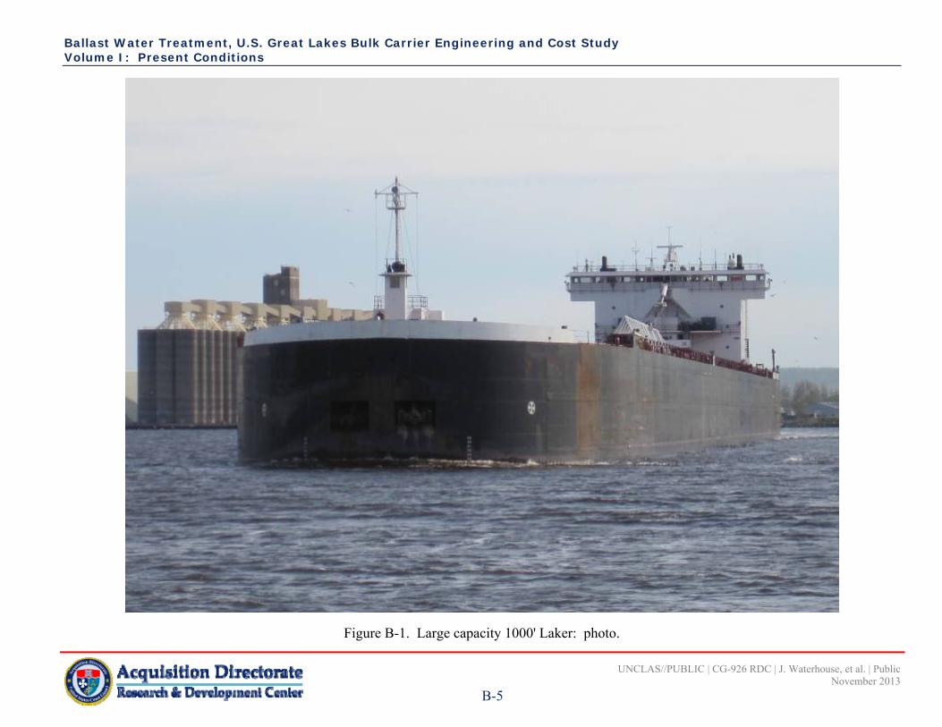
Ballast Water Treatment, U.S. Great Lakes Bulk Carrier Engineering and Cost Study Volume I: Present Conditions
UNCLAS//PUBLIC | CG-926 RDC | J. Waterhouse, et al. | Public November 2013
B-5
Figure B-1. Large capacity 1000' Laker: photo.

Ballast Water Treatment, U.S. Great Lakes Bulk Carrier Engineering and Cost Study Volume I: Present Conditions
UNCLAS//PUBLIC | CG-926 RDC | J. Waterhouse, et al. | Public November 2013
B-6
This page intentionally left blank.

Ballast Water Treatment, U.S. Great Lakes Bulk Carrier Engineering and Cost Study Volume I: Present Conditions
UNCLAS//PUBLIC | CG-926 RDC | J. Waterhouse, et al. | Public November 2013
B-7
Figure B-2. Large capacity 1000' Laker: general arrangement.

Ballast Water Treatment, U.S. Great Lakes Bulk Carrier Engineering and Cost Study Volume I: Present Conditions
UNCLAS//PUBLIC | CG-926 RDC | J. Waterhouse, et al. | Public November 2013
B-8
Figure B-3. Large capacity 1000' Laker: engine room arrangement.

Ballast Water Treatment, U.S. Great Lakes Bulk Carrier Engineering and Cost Study Volume I: Present Conditions
UNCLAS//PUBLIC | CG-926 RDC | J. Waterhouse, et al. | Public November 2013
B-9
Figure B-4. Large capacity 1000' Laker: ballast water diagram.

Ballast Water Treatment, U.S. Great Lakes Bulk Carrier Engineering and Cost Study Volume I: Present Conditions
UNCLAS//PUBLIC | CG-926 RDC | J. Waterhouse, et al. | Public November 2013
B-10
This page intentionally left blank.

Ballast Water Treatment, U.S. Great Lakes Bulk Carrier Engineering and Cost Study Volume I: Present Conditions
UNCLAS//PUBLIC | CG-926 RDC | J. Waterhouse, et al. | Public November 2013
C-1
APPENDIX C OLDER, SMALL CAPACITY 700' – 800' LAKER
C.1 Older, Small Capacity 700' - 800' Laker: Vessel Construction
Table C-1 lists the older, small capacity 700' - 800' 1000’ Laker principal characteristics. The vessel is built from ABS ordinary strength steel or equal for plating and framing. The structure is designed for a midsummer draft of 27.04’. The general structural arrangement of the vessel is transversely framed with transverse web frames spaced, in general, at 3.0’. The bow section of the vessel has a semi-ship shape bow, with the collision bulkhead located at frame 16, and the stern shape is a ship shape “wine glass”, with a centerline skeg, and stern frame supporting the rudder lower bearing. This ship has camber on the spar deck, with sheer forward and aft. The vessel was lengthened by 102.0’ in 1976.
Table C-1. Older, small capacity 700' - 800' Laker: principal characteristics.
Length at Waterline 742.0’ after 102.0’ lengthening Beam Molded 72.0’ Draft 27.0’ Depth, Molded, Main Deck 36.0’ Camber of Main Deck, Straight Line 1.5’ in ½ beam Lightship 9,150 lt Gross Tonnage 15,179 Net Tonnage (Registered) 11,330 Number of Cargo Holds 14 Cargo Type Iron Ore Pellets, Coal, Limestone Deadweight Tonnage 25,601 lt (26,011 mt) Number of Ballast Tanks 18 Ballast Tank Capacity 62, 150 mt Power Plant 7,700 hp (Steam) Year Built 1952/1976 lengthened Shipyard Manitowoc Shipbuilding, Inc./Fraser Shipyard
C.2 Older, Small Capacity 700' - 800' Laker: Vessel Arrangement
The vessel is arranged with a deckhouse forward and aft, with accommodations forward, and with accommodations and propulsion located aft (Figure C-1 and Figure C-2). A self-unloading inclined belt system is fitted at the forward end of the cargo block, with a top side “A” frame through the spar deck, where the cargo then transfers to the cargo boom conveyor. Forward, the pilothouse is located over the accommodations. Aft, the engine room space (Figure C-3) is 102.0’ long over 34 frames of 3’ spacing, and the hull extends another 39.0’ aft of the machinery space. The cargo block is divided into seven cargo holds which vary in length from 90.0’ for hold one, 72.0’ for holds two, three, and six, 96.0’ for hold four, 78.0’ for hold five, and 75.0’ for hold seven, for a total length of 555.0’. The cargo holds are comprised of 35-degree transverse slopes feeding gravity type cargo gates, where the cargo flows onto conveyor belts, one port, one starboard, rising forward and feeding an inclined belt on the centerline via a transverse loading chute feeding the inclined conveyor and the boom conveyor. The spar deck has hatches with covers that are removed and stacked by a hatch cover crane that allows the vessel to be loaded at a timely rate of some 5,600 tons per hour.

Ballast Water Treatment, U.S. Great Lakes Bulk Carrier Engineering and Cost Study Volume I: Present Conditions
UNCLAS//PUBLIC | CG-926 RDC | J. Waterhouse, et al. | Public November 2013
C-2
C.3 Older, Small Capacity 700' - 800' Laker: Ballast System
The installed ballast system is capable of counter-acting the loading rate of the shore facility to keep the vessel in close vertical tolerance to the loading facility. Table C-2 (Fraser Shipyards, Inc, 1975a; Fraser Shipyards, Inc., 1975b) provides the capacity of the ballast tanks. The ballast system is comprised of one electric motor driven pump on each side (total of two (Figure C-4)). The combined capacity is 21,000 gpm (4,770 mt per hour ). Each ballast pump is a 150 hp motor-driven, rated at 10,500 gpm (2,380 mt per hour) with 40’ total dynamic head. The ballast system on this vessel is augmented by one smaller electric motor driven pump on each side of the vessel (total of two). Each smaller ballast pump has a capacity of 2,000 gpm (450 mt per hour). The combined capacity of the two systems is 25,000 gpm (5,680 mt per hour)(see Table C-3). The ballast system on this 768.25’ vessel is a manifold and single line per tank type, with the single lines leading down each side of the vessel through the ballast tanks in a raft of pipes. The line for ballast tanks 1-8 P/S is a 10” diameter pipe, with a 6” diameter branch line for the forepeak tank. Each ballast tank suction line is fitted with a suction box located close to the vessel bottom.
Table C-2. Older, small capacity 700' - 800' Laker: ballast tank capacities.
Tank Tank Length (ft)
Weight (mt) Cubic Feet
Forepeak 24.0 253.0 8,930 No. 1 Port 66.0 497.9 17,580 No. 1 Starboard 66.0 497.9 17,580 No. 2 Port 72.0 672.6 23,750 No. 2 Starboard 72.0 672.6 23,750 No. 3 Port 72.0 649.3 22,930 No. 3 Starboard 72.0 649.3 22,930 No. 4 Port 72.0 649.3 22,930 No. 4 Starboard 72.0 649.3 22,930 No. 5 Port 96.0 865.7 30,570 No. 5 Starboard 96.0 865.7 30,570 No. 6 Port 78.0 703.1 24,830 No. 6 Starboard 78.0 703.1 24,830 No. 7 Port 72.0 649.3 22,930 No. 7 Starboard 72.0 649.3 22,930 No. 8 Port 75.0 653.3 23,070 No. 8 Starboard 75.0 653.3 23,070 Trim Tank Port 36.0 241.8 8,540 Trim Tank Starboard 36.0 241.8 8,540 No. 9 Port 69.0 170.7 6,030 No. 9 Starboard 69.0 170.7 6,030 Afterpeak 36.0 174.0 6,140
TOTALS 11,933.0 421,390

Ballast Water Treatment, U.S. Great Lakes Bulk Carrier Engineering and Cost Study Volume I: Present Conditions
UNCLAS//PUBLIC | CG-926 RDC | J. Waterhouse, et al. | Public November 2013
C-3
Table C-3. Older, small capacity 700' - 800' Laker: ballast pumping capacities.
Pumps Gallons/Hour mt/Hour Hours to Empty21,000 gpm Main Ballast (2) 1,260,000 4,770 2.5 4,000 gpm Auxiliary (2) 240,000 900 13.3
TOTAL CAPACITY 1,500,000 5,670 2.1 C.4 Older, Small Capacity 700' - 800' Laker: Ballast Water Management
The vessel is ballasted to maintain safe and efficient operations as discussed in Section 3. Table C-2 shows a listing of the ballast tanks. Table C-4 provides several different ballast conditions. The maximum pump capacity is reduced by 20 percent to account for changes in discharge head.
Table C-4. Older, small capacity 700' - 800' Laker: operational ballast conditions.
Condition, Tanks
w/Water Tanks
Total mt
Pump Rate (0.8) Hours
Draft Forward
(ft)
Draft Aft(ft)
Light Ballast 4,5,6,7,8,9 & Aftpeak 7556 3,816 mt/hr 2.0 6.3 18.4 Medium Ballast 3,4,5,6,7,8,9 & Aftpeak 8,855 3,816 mt/hr 2.3 9.0 19.5
Heavy Ballast 2, 3, 4, 5, 6, 7, 8, 9, Trim Tank & Aftpeak 10,684 3,816 mt/hr 2.9 19.5 19.9
C.5 Older, Small Capacity 700' - 800' Laker: Electrical Power Requirements
The summary of electrical load is used to size and select the generators to safely operate the vessel. The calculation is unique to vessel design and operation. The vessel has different electrical load requirement depending the operating condition (i.e., docking, loading, etc.); see Table C-5. Since not all equipment operates 100% of the time, a load factor is assigned. The load factor is based on design requirement, specification, and engineering experience. For this vessel the load factors during loading are 1.00 for one ballast pump and 0.80 for the other. The difference between the load factors would be a result of pump size and cargo loading rate.
C.6 References
Fraser Shipyards, Inc. (1975a). Tank capacity curves. Drawing MAN 415-S29-1-21, Rev 0. Fraser Shipyards, Inc. (1975b). Capacity plan. Drawing MAN 415 S29-1-23.

Ballast Water Treatment, U.S. Great Lakes Bulk Carrier Engineering and Cost Study Volume I: Present Conditions
UNCLAS//PUBLIC | CG-926 RDC | J. Waterhouse, et al. | Public November 2013
C-4
Table C-5. Older, small capacity 700' - 800' Laker: summary electrical of load.
Load Group Rated(hp)
Motor Input (kW)
At Sea Maneuvering Loading Unloading
Load Factor
Load(kW)
Load Factor
Load(kW)
Load Factor
Load(kW)
Load Factor
Load (kW)
Ballast System 248.00 0.00 0.00 180.00 180.00 Ship Service Auxiliary 608.90 162.91 152.38 171.47 251.43 Heating 1.00 0.08 0.08 0.08 0.08 Ventilation System 86.80 76.40 74.00 64.40 59.60 Deck Equipment 257.60 0.00 0.00 73.20 67.28 Bow Thruster Auxiliary 804.00 0.00 804.00 0.00 0.00 Conveyor System Auxiliary 1095.20 0.00 0.00 0.00 1062.94 Propulsion 163.00 16.00 64.00 0.00 0.00 Lighting 96.00 67.20 67.20 59.52 67.20 Machine Shop 35.20 0.60 0.48 0.00 0.48 Galley 82.40 24.20 21.80 21.80 21.80 Misc 6.60 1.20 0.00 0.00 0.00
Total 3484.70 348.59 1183.94 570.47 1710.81

Ballast Water Treatment, U.S. Great Lakes Bulk Carrier Engineering and Cost Study Volume I: Present Conditions
UNCLAS//PUBLIC | CG-926 RDC | J. Waterhouse, et al. | Public November 2013
C-5
Figure C-1. Older, small capacity 700' - 800' Laker: photo.

Ballast Water Treatment, U.S. Great Lakes Bulk Carrier Engineering and Cost Study Volume I: Present Conditions
UNCLAS//PUBLIC | CG-926 RDC | J. Waterhouse, et al. | Public November 2013
C-6
This page intentionally left blank.

Ballast Water Treatment, U.S. Great Lakes Bulk Carrier Engineering and Cost Study Volume I: Present Conditions
UNCLAS//PUBLIC | CG-926 RDC | J. Waterhouse, et al. | Public November 2013
C-7
Figure C-2. Older, small capacity 700' - 800' Laker: general arrangement.

Ballast Water Treatment, U.S. Great Lakes Bulk Carrier Engineering and Cost Study Volume I: Present Conditions
UNCLAS//PUBLIC | CG-926 RDC | J. Waterhouse, et al. | Public November 2013
C-8
Figure C-3. Older, small capacity 700' - 800' Laker: engine room arrangement.
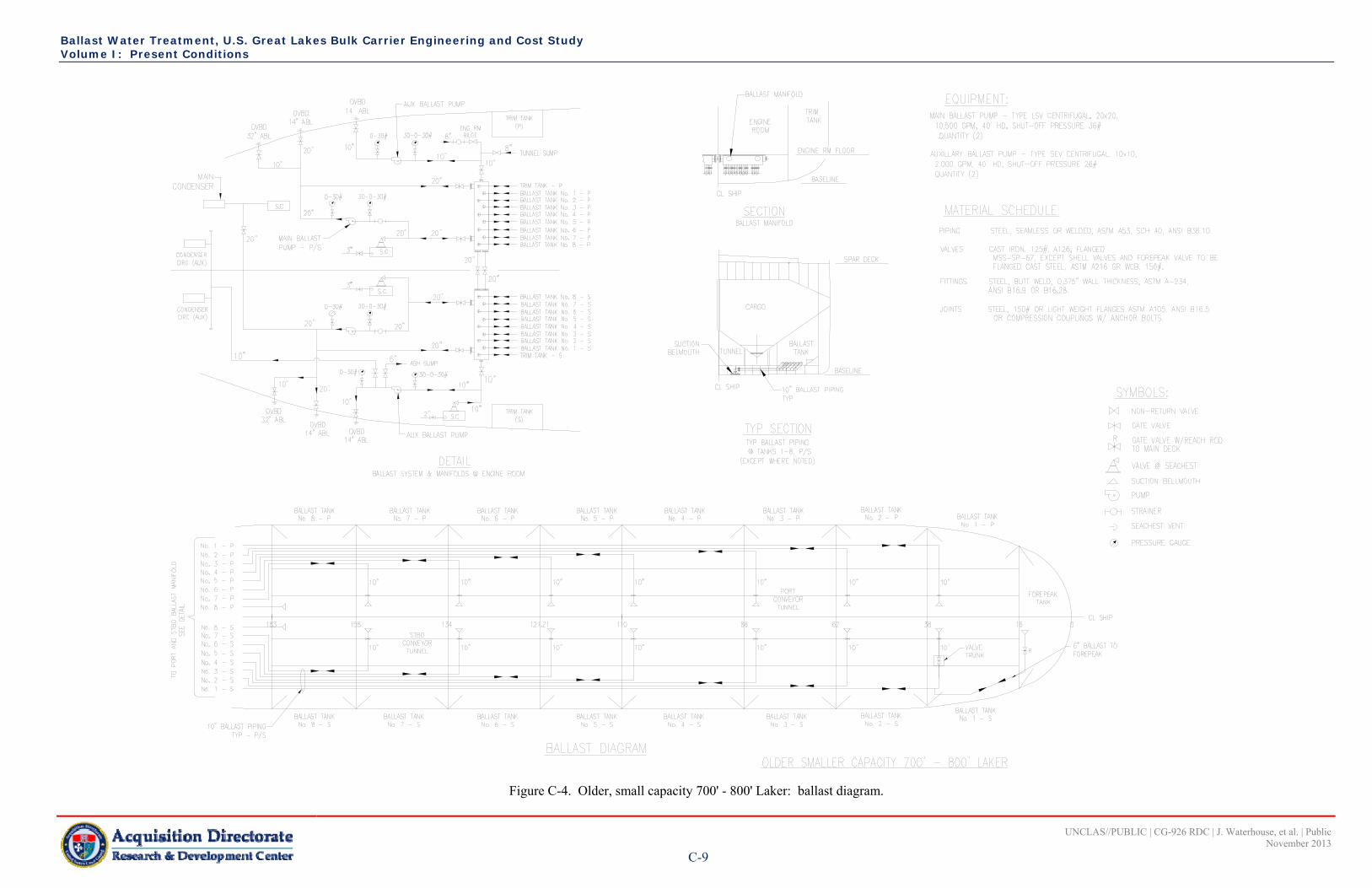
Ballast Water Treatment, U.S. Great Lakes Bulk Carrier Engineering and Cost Study Volume I: Present Conditions
UNCLAS//PUBLIC | CG-926 RDC | J. Waterhouse, et al. | Public November 2013
C-9
Figure C-4. Older, small capacity 700' - 800' Laker: ballast diagram.

Ballast Water Treatment, U.S. Great Lakes Bulk Carrier Engineering and Cost Study Volume I: Present Conditions
UNCLAS//PUBLIC | CG-926 RDC | J. Waterhouse, et al. | Public November 2013
C-10
This page intentionally left blank.

Ballast Water Treatment, U.S. Great Lakes Bulk Carrier Engineering and Cost Study Volume I: Present Conditions
UNCLAS//PUBLIC | CG-926 RDC | J. Waterhouse, et al. | Public November 2013
D-1
APPENDIX D NEWER, INTERMEDIATE CAPACITY 800' – 900' LAKER
D.1 Newer, Intermediate Capacity 800' – 900' Laker: Vessel Construction
Table D-1 lists the newer, intermediate capacity 800' - 900' Laker principal characteristics. The vessel is built from ABS high-strength steel AH36 or equal for plating and framing. The structure is designed for a scantling draft of 30.0’, with a section modulus capable of a loaded draft of 27.5’. The general structural arrangement of the vessel is longitudinally framed with transverse web frames spaced, in general, at 8.0’. The bow section of the vessel has radial cant frames back to the collision bulkhead with a cylindrical bow shape and the stern shape is a barge rake, with a tunnel leading into the tug notch for reduced transom drag. The stern has a deep notch cut into it to fit a 135.33’ twin screw pusher tug, with 10,500 horsepower.
Table D-1. Newer, intermediate capacity 800' – 900' Laker: principal characteristics.
Length at Waterline 740.0’ (without tugboat) Beam Molded 78.0 Draft 27.5’ Depth, Molded, Main Deck 45.0’ Camber of Main Deck, Straight Line - Lightship 6235.16 lt Gross Tonnage 15,823 Net Tonnage (Registered) 15,823 Number of Cargo Holds 7 Cargo Type Iron Ore Pellets, Coal, Limestone Deadweight Tonnage 39,600 lt (40,235 mt) Number of Ballast Tanks 17 Ballast Tank Capacity 24,121 mt Power Plant - Year Built 2000 Shipyard Halter Marine
D.2 Newer, Intermediate Capacity 800' – 900' Laker: Vessel Arrangement
The vessel is an ATB. The barge is 740’ long and the tug is 135’ long. The barge is arranged with a deckhouse aft that is the main support for the 265’ unloading boom conveyor with a loop-type elevating conveyor that feeds it (Figure D-1 and Figure D-2). The self-unloading system is fitted at the aft end of the cargo block and embedded into the machinery space below the main deck and is enclosed by the deckhouse above the main deck. The barge has a small deckhouse forward which houses the anchor windlass, and has a lookout house on top for improved visibility. The aft machinery space is five frames long at 8.0’ each, for 40.0’, and the hull extends another 40.0’ aft of the machinery space. The cargo block is divided into seven cargo holds which vary in length from 120.0’ midship to 72.0’ for hold seven. The cargo holds are comprised of 35-degree transverse slopes feeding gravity-type cargo gates, where the cargo flows onto a single, centerline conveyor belt feeding the loop conveyor and the boom conveyor. The main deck has hatches with covers that are removed and stacked by a hatch cover crane that allows the vessel to be loaded at a timely rate of some 6,098 mt per hour.

Ballast Water Treatment, U.S. Great Lakes Bulk Carrier Engineering and Cost Study Volume I: Present Conditions
UNCLAS//PUBLIC | CG-926 RDC | J. Waterhouse, et al. | Public November 2013
D-2
D.3 Newer, Intermediate Capacity 800' – 900' Laker: Ballast System
The installed ballast system is capable of counter-acting the loading rate of the shore facility to keep the vessel in close vertical tolerance to the loading facility. Table D-2 provides the ballast tank capacities. The ballast system is comprised of one hydraulic motor-driven 14,000 gpm (3,180 mt per hour) pump on each side of the vessel with a combined capacity of 28,000 gpm (6,360 mt per hour) (see Table D-3), arranged as shown in Figure D-3 (shown at the end of this appendix). The ballast pumps are each driven by a 225 hp hydraulic motor turning at 600 rpm, direct coupled to the pump shafts. The ballast piping system on this 740’ vessel is a single header leading down each side of the vessel and located in the ballast tanks with branch lines to each tank (Figure D-4). The main header is a 24” diameter pipe for the most of the length that tapers to a 12” diameter at the forward extreme, and the forepeak tank. Each ballast tank is fitted with a 12” diameter branch line and has a remotely controlled powered valve located in the unloading tunnel, and a suction box which is located close to the vessel bottom for optimum performance. The vessel also has a stripping system comprised of 14 submersible pumps, one in each tank, with a pumping capacity of 400 gpm (90 mt per hour) each through a 4” diameter pipe tied in to the 12” tank branch lines. The total ballast discharge rate for this vessel is 33,600 gpm (7,620 mt per hour) maximum, with all 16 pumps at maximum capacity.
Table D-2. Newer, intermediate capacity 800' – 900' Laker: ballast tank capacities.
Tank Tank Length (ft)
Weight (mt) Cubic Feet
Forepeak 28.0 828.2 29,250 No. 1 Port 80.0 1,244.6 43,950 No. 1 Starboard 80.0 1,244.6 43,950 No. 2 Port 72.0 1,301.4 45,960 No. 2 Starboard 72.0 1,301.4 45,960 No. 3 Port 96.0 1,735.8 61,300 No. 3 Starboard 96.0 1,735.8 61,300 No. 4 Port 120.0 2,169.7 76,620 No. 4 Starboard 120.0 2,169.7 76,620 No. 5 Port 96.0 1,735.8 61,300 No. 5 Starboard 96.0 1,735.8 61,300 No. 6 Port 96.0 1,735.8 61,300 No. 6 Starboard 96.0 1,735.8 61,300 No. 7 Port 72.0 1,370.7 48,410 No. 7 Starboard 72.0 1,370.7 48,410 Machinery Space CL VOID 0.0 0.0 Aft Ballast Port 24.0 352.7 12,460 Aft Ballast Starboard 24.0 352.7 12,460 After Peak Port VOID 0.0 0.0 After Peak Starboard VOID 0.0 0.0
TOTALS 632.0 24,121.2 851,850

Ballast Water Treatment, U.S. Great Lakes Bulk Carrier Engineering and Cost Study Volume I: Present Conditions
UNCLAS//PUBLIC | CG-926 RDC | J. Waterhouse, et al. | Public November 2013
D-3
Table D-3. Newer, intermediate capacity 800' – 900' Laker: ballast pumping capacities.
Pumps Gallons/Hour mt/Hour Hours to Empty Ballast Tanks 14,000 gpm (2) Ballast 1,680,000 6,360 3.8 400 gpm (14) Stripping 336,000 1,260 19.1
TOTAL CAPACITY 2,016,000 7,620 3.2 D.4 Newer, Intermediate Capacity 800' – 900' Laker: Ballast Water Management
The vessel is ballasted to maintain safe and efficient operations as discussed in Section 3. Table D-2 shows a listing of the ballast tanks. Since this vessel is actually two vessels (tug and barge), the combination has the added required for ballasting during the connection of the tug to the barge. The minimum ballast condition for the barge during the connection is the River Ballast (Table D-4) condition of 17,415 mt. This results in a draft of 16.2 feet. Excerpts from the Guidance Manual for Loading (Bay Engineering, 2011) are listed in Table D-4. The maximum pump capacity is reduced by 20 percent to account for changes in discharge head.
Table D-4. Newer, intermediate capacity 800' – 900' Laker: operational ballast conditions. (Bay Engineering, 2011)
Condition Tanks w/Water Total mt
Pump Rate (0.8)
Hours to Empty
Draft (ft) Forward Aft
Light Ballast (Towing) 1R, 2, 3R, 4, 5R, 6, & 7R 10,541 5,088 mt/hr 2.1 10.28 13.17River Ballast 1, 3, 4, 5, 6, & 7 17,415 5,088 mt/hr 3.4 14.03 18.3 Medium Ballast 1, 2(50% full), 3, 4,
5(75% full), 6, & 7 20,427 5,088 mt/hr 4.0 16.89 19.33
Medium/Heavy Ballast 1, 2(75% full), 3, 4, 5, 6, & 7
21,946 5,088 mt/hr 4.3 18.34 19.83
Heavy Ballast 1, 2, 3, 4, 5, 6, 7, & aftpeak
22,302 5,088 mt/hr 4.4 18.68 21.24
Full Ballast ALL 24,121 5,088 mt/hr 4.7 RTank has a residual (approximately 1%) amount of water. D.5 Newer, Intermediate Capacity 800' – 900' Laker: Electrical Power
Requirements
The summary of electrical load is used to size and select the generators to safely operate the vessel. The calculation is unique to vessel design and operation. The electrical summary loads for this vessel include the tugboat and the barge; see Table D-5. Since the tug provides power to the barge during between ports, the barge loads are included in the tug electrical summary loads in transit. These barge loads during transit are used to size the generators on the tugboat. The generators on the barge are principally used during unloading, loading, and docking. These operations are not part of the tugboat operations and the generators are sized for these conditions.
D.6 References
Bay Engineering. (2011). Guidance manual for loading. Drawing 801-03 Rev B.

Ballast Water Treatment, U.S. Great Lakes Bulk Carrier Engineering and Cost Study Volume I: Present Conditions
UNCLAS//PUBLIC | CG-926 RDC | J. Waterhouse, et al. | Public November 2013
D-4
Table D-5. Newer, intermediate capacity 800' - 900' Laker: summary of electrical load.
Auxiliary Rated(hp)
Motor/Input(kW)
Tug: At Sea (loads are tug-supplied power) Barge Generator
Remarks Summer Winter Unloading Loading Docking
LoadFactor
Load(kW)
LoadFactor
Load(kW)
Load Factor
Load(kW)
LoadFactor
Load(kW)
LoadFactor
Load(kW)
UNLOADING MCC D4 Charger, Battery, Navigation Lights 0.5 .20 0.1 .20 0.1 D4 Charger, Battery, Gen Set & Hyd 0.5 .20 0.1 .20 0.1 D4 Charger, Battery, Dual, Diesel Hyd Eng 0.5 .20 0.1 .20 0.1 .20 0.1 .20 0.1 .20 0.1 D4 Charger, Battery, Dual, Diesel Hyd Eng 0.5 .20 0.1 .20 0.3 .20 0.1 .20 0.1 .20 0.1 D4 Charger, Battery, Dual, Diesel Hyd Eng 0.5 .20 0.1 .20 0.1 .20 0.1 .20 0.1 .20 0.1 T4 Compressor, Air (S), No. 1 5 4.1 .30 1.2 .40 1.6 .50 2.1 .50 2.1 .10 0.4 T14 Compressor, Air (S), No. 2 15 12.3 .50 6.2 .50 6.2 .10 1.2 T14 Fan, Supply, Upper Machy Room, (P) 15 12.3 .90 11.1 .50 6.2 .50 6.2 Variable speed, half speed winter T14 Fan, Supply, Upper Machy Room, (S) 15 12.3 .90 11.1 .50 6.2 .50 6.2 Variable speed, half speed winter T75 Heating, Upper Machy, Void 90.0 .48 43.2 0.0 T75 Heating, Lower Machy Aft & Tunnel 60.0 .48 28.8 .80 48.0 T9 Heater, Unit, Actuator Room 15.0 .40 6.0 .80 12.0 T4 Heater, Hydraulic Oil, Storage Tanks, (S) 8.0 .40 3.2 .55 4.4 T4 Heater, Hydraulic Oil, Storage Tanks, (P) 8.0 .40 3.2 .55 4.4 T4 Heater, J W Gen 4.0 .35 1.4 .50 2.0 T4 Heater, J W Pump, Eng (P) 3.0 .35 1.1 .50 1.5 T4 Heater, J W Pump, Eng (P) 3.0 .35 1.1 .50 1.5 T4 Heater, J W Pump, Eng (P) 3.0 .35 1.1 .50 1.5 T4 Heater, J W Pump, Eng (P) 3.0 .35 1.1 .50 1.5 T4 Heater, J W Pump, Eng (S) 3.0 .35 1.1 .50 1.5 T4 Heater, J W Pump, Eng (S) 3.0 .35 1.1 .50 1.5 T4 Heater, J W Pump, Eng (S) 3.0 .35 1.1 .50 1.5 T4 Heating, Radiant, Control booth (P) 1.0 .24 0.2 .24 0.2 .24 0.2 T4 Heating, Radiant, Control booth (S) 1.0 .24 0.2 .24 0.2 .24 0.2 Sheet 1 Total kW 252 17 102 91 21 15

Ballast Water Treatment, U.S. Great Lakes Bulk Carrier Engineering and Cost Study Volume I: Present Conditions
UNCLAS//PUBLIC | CG-926 RDC | J. Waterhouse, et al. | Public November 2013
D-5
Table D-5. Newer, intermediate capacity 800' - 900' Laker: summary of electrical load (Continued).
Auxiliary Rated(hp)
Motor/Input(kW)
Tug: At Sea (loads are tug-supplied power) Barge Generator
Remarks Summer Winter Unloading Loading Docking
LoadFactor
Load(kW)
LoadFactor
Load(kW)
Load Factor
Load(kW)
LoadFactor
Load(kW)
LoadFactor
Load(kW)
T50 Panel, Lighting, L2, Aft 7.5 .10 0.8 .10 0.8 .90 6.8 .90 6.8 .90 6.8 T14 Panel, Lighting, L3, Fwd \ Deck 4.0 .10 0.4 .10 0.4 .90 3.6 .90 3.6 .90 3.6 T23 Panel, Lighting, L4, Aft Boom all-lts 5.5 .09 0.5 .09 0.5 .50 2.8 .50 2.8 .50 2.8 T23 Panel, Lighting, L5, Tunnel 4.0 .09 0.4 .09 0.4 1.00 4.0 1.00 4.0 1.00 4.0 T23 Panel, Lighting, L6, Signal Lts, Tunnel 7.5 .90 6.8 .90 6.8 .90 6.8 7, T4 Pump, Anti-Freeze 1.5 1.2 .10 0.1 .20 0.2 3, T4 Pump, Bilge, Aft, (P) 5 4.1 .10 0.4 .10 0.4 .10 0.4 .10 0.4 .10 0.4 3, T4 Pump, Bilge, Aft, (S) 5 4.1 .10 0.4 .10 0.4 .10 0.4 .10 0.4 .10 0.4 T23 Panel, Lighting, L7, Cargo Hold 13.0 .90 11.7 .90 11.7 .60 7.8 13, T23 Pump, Cooling, Raw water, #3 25 20.5 .90 18.5 .20 4.1 .40 8.2 13, T23 Pump, Cooling, Raw water, #2 25 20.5 .90 18.5 .20 4.1 .40 8.2 7, T4 Pump, Cooling, Raw water, Gen, #1 3 2.5 .90 2.2 .90 2.2 .90 2.2 14, T23 Pump, Dredge, (P), Aft Fr 80 30 24.6 .50 12.3 14, T23 Pump, Dredge, (S), Fwd Fr 5 30 24.6 .50 12.3 10, T23 Boom Swing Hyd Unit 20 16.4 .40 6.6 .40 6.6 24, T23 Hyd Standby Mooring & Boarding Ladder 25 20.5 .30 6.2 .30 6.2 T23 Panel, Lighting, L8/L9, Deck & Anchor Lts 1.7 .20 0.3 .20 0.3 .60 1.0 .60 1.0 .60 1.0 17, T4 Pump, Stripping, #, 1 8 6.6 .80 5.2 17, T4 Pump, Stripping, #, 2 8 6.6 18, T4 Pump, Stripping, #, 3 8 6.6 .80 5.2 18, T4 Pump, Stripping, #, 4 8 6.6 19, T4 Pump, Stripping, #, 5 8 6.6 19, T4 Pump, Stripping, #, 6 8 6.6 .80 5.2 20, T4 Pump, Stripping, #, 7 8 6.6 20, T4 Pump, Stripping, #, 8 8 6.6 21, T4 Pump, Stripping, #, 9 8 6.6 .80 5.2 21, T4 Pump, Stripping, #, 10 8 6.6 22, T4 Pump, Stripping, #, 11 8 6.6 22, T4 Pump, Stripping, #, 12 8 6.6 .80 5.2 23, T4 Pump, Stripping, #, 13 8 6.6 23, T4 Pump, Stripping, #, 14 8 6.6 .80 5.2 T23 Panel, Lighting, L8/L9, Deck & Anchor Lts 2.8 .10 0.3 .10 0.3 .60 1.7 .60 1.7 .60 1.7 Sheet 2 Total kW 277 3 3 114 81 58

Ballast Water Treatment, U.S. Great Lakes Bulk Carrier Engineering and Cost Study Volume I: Present Conditions
UNCLAS//PUBLIC | CG-926 RDC | J. Waterhouse, et al. | Public November 2013
D-6
Table D-5. Newer, intermediate capacity 800' - 900' Laker: summary of electrical load (Continued).
Auxiliary Rated(hp)
Motor/Input(kW)
Tug: At Sea (loads are tug-supplied power) Barge Generator
Remarks Summer Winter Unloading Loading Docking
LoadFactor
Load(kW)
LoadFactor
Load(kW)
Load Factor
Load(kW)
LoadFactor
Load(kW)
LoadFactor
Load(kW)
L1- 1, D9 Ballast & Stripping (P/S)Console Valve Control 1.0 .20 0.2 .20 0.2 .20 0 L1- 2, D4 Ballast Tank Gauge System 0.8 .10 0.08 .10 0.1 L1- 3, D4 Vibrator system, (S) Panel 0.1 .30 0.0 L1- 3A, D4 Vibrator System, (P) Panel 0.1 .30 0.0 L1- 5, D4 Space Heater, Gen 0.6 .10 0.06 .55 0.3
P401- 16, T4 Pump, Transfer, Waste Oil, (dirty oil) #1 3 2.5 .20 0.5 .20 0.5 P402- 16, T4 Pump, Transfer, Waste Oil, (dirty oil) #2 3 2.5 0.0 0.0 P402- 8, T4 Pump, Vacuum Priming, (P), #1 5 4.1 0.0 .40 1.6 .50 2.1 P404- 1, T4 Heater, Fwd Machy Room 5.0 P405- 1, T4 Heater, De-Icing 5.0 .45 2.3 P401- 2, T50 Pump, General Service 50 41.0 .20 8.2 .20 8.2 P402- 2, T50 Pump, Washdown Service 50 41.0 .20 8.2 .20 8.2 .50 20.5 P405, 2, T14 Pump, Process, De-Icing 15 12.3 .45 5.5 .45 5.5 P405- 3, T4 Pump, Feed, De-Icing 5 4.1 .45 1.8 P407, T23 Receptacle, Main Deck, Aft 0.8 .10 0.1 .10 0.1 P404- 2, T4 Heater, Fwd Machy Room 5.0 .55 2.8 P408, T23 Receptacles, Upper Machy Room, P/S 3.0 .05 0.2 .05 0.2 L1- 6, D4 Gate Seal Control & Alarm 0.2 .30 0.06 .30 0.1 L1- 7, D4 Boom Topping & Slew Control 0.6 .70 0.4 L1- 12, D9 Receptacle, 2nd Deck, (S), Control Room 1.0 .40 0.4 .40 0.4 .40 0.4 L1- 13, D9 Receptacle, 2nd Deck, (P), Control Room 1.0 .40 0.4 .40 0.4 .40 0.4 L1- 14, D4 Trim Indicator 0.1 .70 0.1 .70 0.1
P401- 15, T4 Separator, Oil/Water, (S) 1 0.8 .05 0.04 .05 0.04 L1- 17, D4 Lights, Actuator Room 0.6 .20 0.12 .20 0.1 .90 0.5 .90 0.5 .90 0.5 L1- 18, D4 Engine Power Control, (P) 0.5 .90 0.5 L1- 21, D4 Engine Power Control, (S) 0.5 .90 0.5 .50 0.3
P404- 3, T4 Pump, Case Drain Unit 5 4.1 .20 0.82 .20 0.8 L1- 8, D9 Winch, Mooring Controls (6) 0.5 .30 0.2 .60 0.3 .60 0.3 .60 0.3
P404- 4, T4 Bowthruster, Hyd 5 4.1 .70 2.9 Sheet 3 Total kW 141 14 20 21 33

Ballast Water Treatment, U.S. Great Lakes Bulk Carrier Engineering and Cost Study Volume I: Present Conditions
UNCLAS//PUBLIC | CG-926 RDC | J. Waterhouse, et al. | Public November 2013
D-7
Table D-5. Newer, intermediate capacity 800' - 900' Laker: summary of electrical load (Continued).
Auxiliary Rated(hp)
Motor/Input(kW)
Tug: At Sea (loads are tug-supplied power) Barge Generator
Remarks Summer Winter Unloading Loading Docking
LoadFactor
Load(kW)
LoadFactor
Load(kW)
Load Factor
Load(kW)
LoadFactor
Load(kW)
LoadFactor
Load(kW)
L1- 1, D9 Ballast & Stripping (P/S)Console Valve Control 1.0 .20 0.2 .20 0.2 .20 0 L1- 2, D4 Ballast Tank Gauge System 0.8 .10 0.08 .10 0.1 L1- 3, D4 Vibrator system, (S) Panel 0.1 .30 0.0 L1- 3A, D4 Vibrator System, (P) Panel 0.1 .30 0.0 L1- 5, D4 Space Heater, Gen 0.6 .10 0.06 .55 0.3
P401- 16, T4 Pump, Transfer, Waste Oil, (dirty oil) #1 3 2.5 .20 0.5 .20 0.5 P402- 16, T4 Pump, Transfer, Waste Oil, (dirty oil) #2 3 2.5 0.0 0.0 P402- 8, T4 Pump, Vacuum Priming, (P), #1 5 4.1 0.0 .40 1.6 .50 2.1 P404- 1, T4 Heater, Fwd Machy Room 5.0 P405- 1, T4 Heater, De-Icing 5.0 .45 2.3 P401- 2, T50 Pump, General Service 50 41.0 .20 8.2 .20 8.2 P402- 2, T50 Pump, Washdown Service 50 41.0 .20 8.2 .20 8.2 .50 20.5 P405, 2, T14 Pump, Process, De-Icing 15 12.3 .45 5.5 .45 5.5 P405- 3, T4 Pump, Feed, De-Icing 5 4.1 .45 1.8 P407, T23 Receptacle, Main Deck, Aft 0.8 .10 0.1 .10 0.1 P404- 2, T4 Heater, Fwd Machy Room 5.0 .55 2.8 P408, T23 Receptacles, Upper Machy Room, P/S 3.0 .05 0.2 .05 0.2 L1- 6, D4 Gate Seal Control & Alarm 0.2 .30 0.06 .30 0.1 L1- 7, D4 Boom Topping & Slew Control 0.6 .70 0.4 L1- 12, D9 Receptacle, 2nd Deck, (S), Control Room 1.0 .40 0.4 .40 0.4 .40 0.4 L1- 13, D9 Receptacle, 2nd Deck, (P), Control Room 1.0 .40 0.4 .40 0.4 .40 0.4 L1- 14, D4 Trim Indicator 0.1 .70 0.1 .70 0.1
P401- 15, T4 Separator, Oil/Water, (S) 1 0.8 .05 0.04 .05 0.04 L1- 17, D4 Lights, Actuator Room 0.6 .20 0.12 .20 0.1 .90 0.5 .90 0.5 .90 0.5 L1- 18, D4 Engine Power Control, (P) 0.5 .90 0.5 L1- 21, D4 Engine Power Control, (S) 0.5 .90 0.5 .50 0.3
P404- 3, T4 Pump, Case Drain Unit 5 4.1 .20 0.82 .20 0.8 L1- 8, D9 Winch, Mooring Controls (6) 0.5 .30 0.2 .60 0.3 .60 0.3 .60 0.3
P404- 4, T4 Bowthruster, Hyd 5 4.1 .70 2.9 Sheet 4 Total kW 141 14 20 21 33 Sheet 1 Total kW 252 17 102 91 21 15 Sheet 2 Total kW 277 3 3 114 81 58 Sheet 3 Total kW 141 14 20 21 33 Sheet 4 Total kW 141 14 20 21 33 Total 669.37 20.17 118.91 225.19 122.40 105.82

Ballast Water Treatment, U.S. Great Lakes Bulk Carrier Engineering and Cost Study Volume I: Present Conditions
UNCLAS//PUBLIC | CG-926 RDC | J. Waterhouse, et al. | Public November 2013
D-8
Figure D-1. Newer, intermediate capacity 800' – 900' Laker: photo.
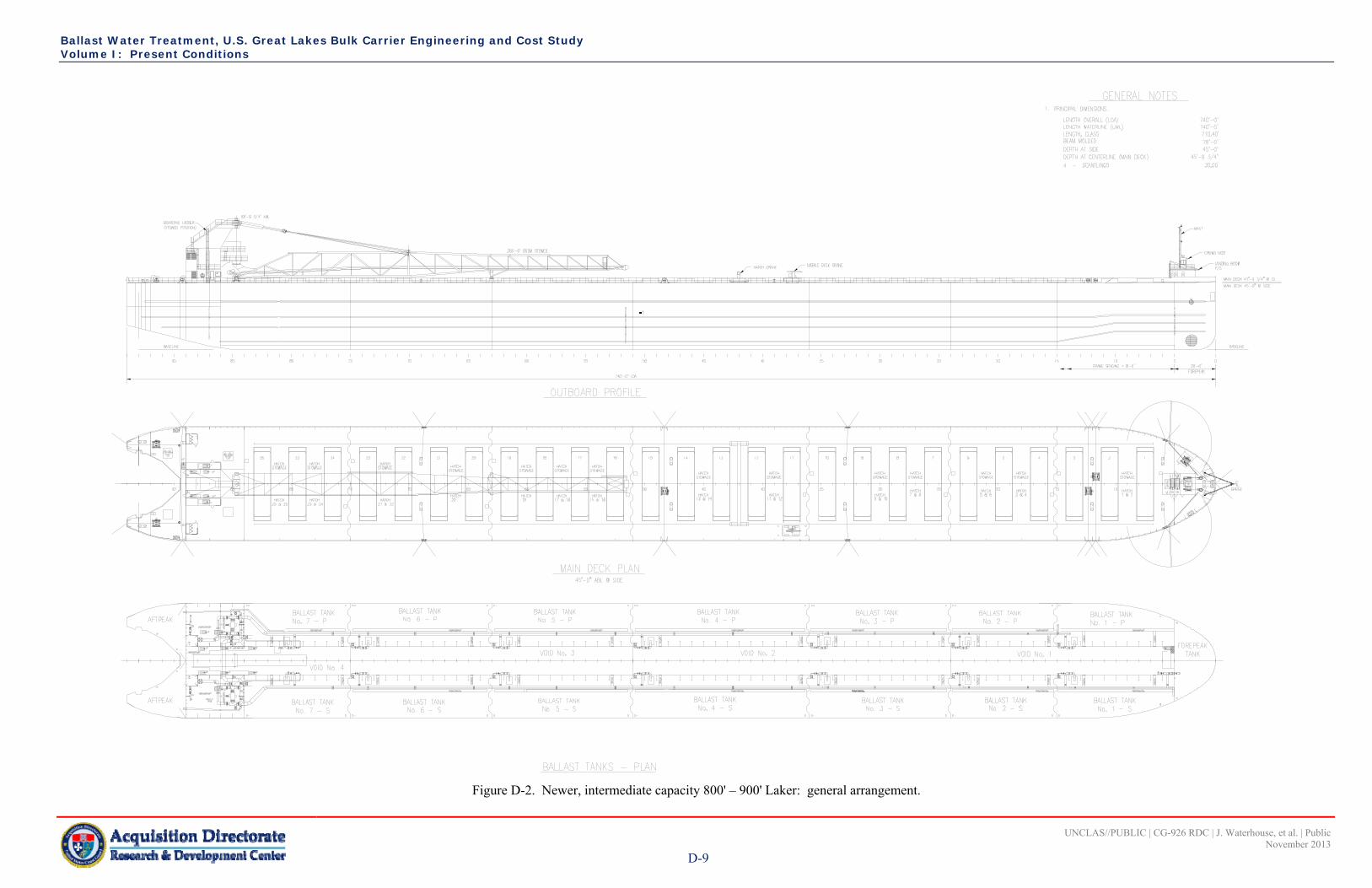
Ballast Water Treatment, U.S. Great Lakes Bulk Carrier Engineering and Cost Study Volume I: Present Conditions
UNCLAS//PUBLIC | CG-926 RDC | J. Waterhouse, et al. | Public November 2013
D-9
Figure D-2. Newer, intermediate capacity 800' – 900' Laker: general arrangement.

Ballast Water Treatment, U.S. Great Lakes Bulk Carrier Engineering and Cost Study Volume I: Present Conditions
UNCLAS//PUBLIC | CG-926 RDC | J. Waterhouse, et al. | Public November 2013
D-10
Figure D-3. Newer, intermediate capacity 800' – 900' Laker: engine room arrangement.

Ballast Water Treatment, U.S. Great Lakes Bulk Carrier Engineering and Cost Study Volume I: Present Conditions
UNCLAS//PUBLIC | CG-926 RDC | J. Waterhouse, et al. | Public November 2013
D-11
Figure D-4. Newer, intermediate capacity 800' – 900' Laker: ballast water diagram.

Ballast Water Treatment, U.S. Great Lakes Bulk Carrier Engineering and Cost Study Volume I: Present Conditions
UNCLAS//PUBLIC | CG-926 RDC | J. Waterhouse, et al. | Public November 2013
D-12
This page intentionally left blank.

Ballast Water Treatment, U.S. Great Lakes Bulk Carrier Engineering and Cost Study Volume I: Present Conditions
UNCLAS//PUBLIC | CG-926 RDC | J. Waterhouse, et al. | Public November 2013
E-1
APPENDIX E SMALL CAPACITY, RIVER CLASS 600’ – 700’ LAKER
Small Capacity, River Class 600’ – 700’ Laker: Vessel Construction
Table E-1 lists the small capacity, river class 600’ – 700’ Laker principal characteristics. The vessel is built from ABS high strength steel or equal for plating and framing. The structure is designed for a midsummer draft of 25.41’. The general structural arrangement of the vessel is transversely framed with transverse web frames spaced, in general, at 6.0’, with partial intermediate frames. The bow section of the vessel has a semi-ship shape bow, with the collision bulkhead located at frame 12, and the stern shape is a ship shape “wine glass”, with a centerline skeg, and stern frame supporting the rudder lower bearing. This ship has no camber or sheer on the spar deck. The vessel was modified by removing the upper side tank bulkheads above the cargo slopes in 1977. The result of the modification allowed the vessel to carry more cargo by enlarging the cargo volume.
Table E-1. Small capacity, river class 600’ – 700’ Laker: principal characteristics.
Length at Waterline 610.0’ Beam Molded 68.0’ Draft 27.5’ Depth, Molded, Main Deck 36,9’ Camber of Main Deck, Straight Line n/a Lightship 5,530.0 lt Gross Tonnage 9,639 Net Tonnage (Registered) 5,700 Number of Cargo Holds 4 Cargo Type Iron Ore Pellets, Coal, Limestone Deadweight Tonnage 19,786 lt Number of Ballast Tanks 17 Ballast Tank Capacity 12,009.1 mt t Power Plant 5,600 hp (Diesel) Year Built 1973 Shipyard American Shipbuilding Co.
Small Capacity, River Class 600’ – 700’ Laker: Arrangement
The vessel is arranged with a deckhouse with accommodations aft, propulsion plant aft, and a forecastle house forward (Figure E-1 and Figure E-2). A self-unloading inclined belt system is fitted at the aft end of the cargo block, with a topside “A” frame on top of the deckhouse for unloading boom support. The engine room space (Figure E-3) is 102.0’ long, over 34 frames of 3’ spacing, and the hull extends another 39.0’ aft of the machinery space. The cargo block is divided into four cargo holds which vary in length from 108.0’ for hold one, 120.0’ for holds two and three, and 90.0’ for hold four, for a total length of 438.0’. The cargo holds are comprised of 35-degree transverse slopes feeding gravity-type cargo gates, where the cargo flows onto a conveyor belt on centerline, rising aft and feeding an inclined belt off centerline via a transverse loading chute feeding another inclined conveyor leading forward to the boom conveyor. The spar deck has hatches with covers removed and stacked by a hatch cover crane that allows the vessel to be loaded at a rate of some 5,000 tons per hour.

Ballast Water Treatment, U.S. Great Lakes Bulk Carrier Engineering and Cost Study Volume I: Present Conditions
UNCLAS//PUBLIC | CG-926 RDC | J. Waterhouse, et al. | Public November 2013
E-2
Small Capacity, River Class 600’ – 700’ Laker: Ballast System
The installed ballast system is capable of counter-acting the loading rate of the shore facility to keep the vessel in close vertical tolerance to the loading facility. Table E-2 provides the capacity of the ballast tanks. The ballast system is comprised of one ballast pump on each side of the vessel (total of two), (Figure E-4) with a combined capacity of 17,000 gpm (3,860 mt per hour). Each pump is rated 8,500 gpm (1,930 mt per hour). The main ballast pumps are centrifugal pumps driven by 120 hp electric motors. The ballast system is augmented with an auxiliary electric-motor-driven centrifugal pump on each side of the vessel, rated at 1,500 gpm (340 mt per hour), combined capacity of 3,000 gpm (680 mt per hour). The combined pumping capacity of the two systems is 20,000 gpm (4,500 mt per hour) (Table E-3). The ballast system on this vessel is a single header leading down each side of the vessel located in a tunnel space inboard of the ballast tanks, with branch lines to each tank. The main header is a 20” diameter pipe for the most of the length that tapers to a 10” diameter at the forward extreme, and the forepeak tank line is 8” diameter. Each ballast tank is fitted with a 10” diameter branch line and has a remotely controlled hydraulic-powered valve located in the ballast tank, and a suction box which is located close to the vessel bottom for optimum performance.
Table E-2. Small capacity, river class 600’ – 700’ Laker: ballast tank capacities.
Tank Tank Length (ft)
Weight (mt) Cubic Feet
Forepeak 24.0 483.8 17,100 No. 1 Port 66.0 599.6 21,200 No. 1 Starboard 66.0 599.6 21,200 No. 2 Port 60.0 758.2 26,800 No. 2 Starboard 60.0 758.2 26,800 No. 3 Port 60.0 758.2 26,800 No. 3 Starboard 60.0 758.2 26,800 No. 4 Port 60.0 758.2 26,800 No. 4 Starboard 60.0 758.2 26,800 No. 5 Port 60.0 758.2 26,800 No. 5 Starboard 60.0 758.2 26,800 No. 6 Port 60.0 758.2 26,800 No. 6 Starboard 60.0 758.2 26,800 No. 7 Port 45.0 624.0 22,000 No. 7 Starboard 45.0 624.0 22,000 No. 8 Port 45.0 658.6 23,300 No. 8 Starboard 45.0 658.6 23,300 Afterpeak 28.0 178.9 6,300
TOTALS 12,009.1 424,400

Ballast Water Treatment, U.S. Great Lakes Bulk Carrier Engineering and Cost Study Volume I: Present Conditions
UNCLAS//PUBLIC | CG-926 RDC | J. Waterhouse, et al. | Public November 2013
E-3
Table E-3. Small capacity, river class 600’ – 700’ Laker: ballast pumping capacities.
Pumps Gallons/Hour mt/Hour Hours to Empty 17,000 gpm (2) Ballast 1,020,000 3,860 3.1 3,000 gpm Auxiliary 180,000 680 17.7
TOTAL CAPACITY 1,200,000 4540 2.6 Small Capacity, River Class 600’ – 700’ Laker: Ballast Water Management
The vessel is ballasted to maintain safe and efficient operations is discussed in Section 3. Table E-2 shows the listing of the ballast tanks. Table E-4 lists excerpts from the Guidance Manual for Loading (R. A. Stern, Inc., 1986). The maximum pump capacity is reduced by 20 percent% to account for changes in discharge head.
Table E-4. Small capacity, river class 600’ – 700’ Laker: operational ballast conditions.
Condition Tanks w/Water Total mt
Pump Rate (0.8) Hours
Draft
Forward(ft)
Aft (ft)
Light Ballast/Thruster Out 5,6,7 & 8 5,598 3,610 mt/hr 1.6 0.92 17.25 Medium Ballast 2,3,4,5,6,7 & 8 10,147 3,610 mt/hr 2.8 3.67 17.58 Deep Ballast FP, 2, 3, 4, 5, 6, 7 & 8 21,899. 3,610 mt/hr 6.1 16.00 18.58 Full Ballast FP, 2, 3, 4, 5, 6, 7, 8 &
aft peak 22,078 3,610 mt/hr 6.1 17.08 20.00
Propeller Out 1 & 2 2,715 3,610 mt/hr 0.8 9.42 7.92 References
R. A. Stern, Inc. (1986). Guidance manual for loading. Drawing 1608-856-01, Rev 1.

Ballast Water Treatment, U.S. Great Lakes Bulk Carrier Engineering and Cost Study Volume I: Present Conditions
UNCLAS//PUBLIC | CG-926 RDC | J. Waterhouse, et al. | Public November 2013
E-4
Figure E-1. Small capacity, river class 600’ – 700’ Laker: photo.

Ballast Water Treatment, U.S. Great Lakes Bulk Carrier Engineering and Cost Study Volume I: Present Conditions
UNCLAS//PUBLIC | CG-926 RDC | J. Waterhouse, et al. | Public November 2013
E-5
Figure E-2. Small capacity, river class 600’ – 700’ Laker: general arrangement.
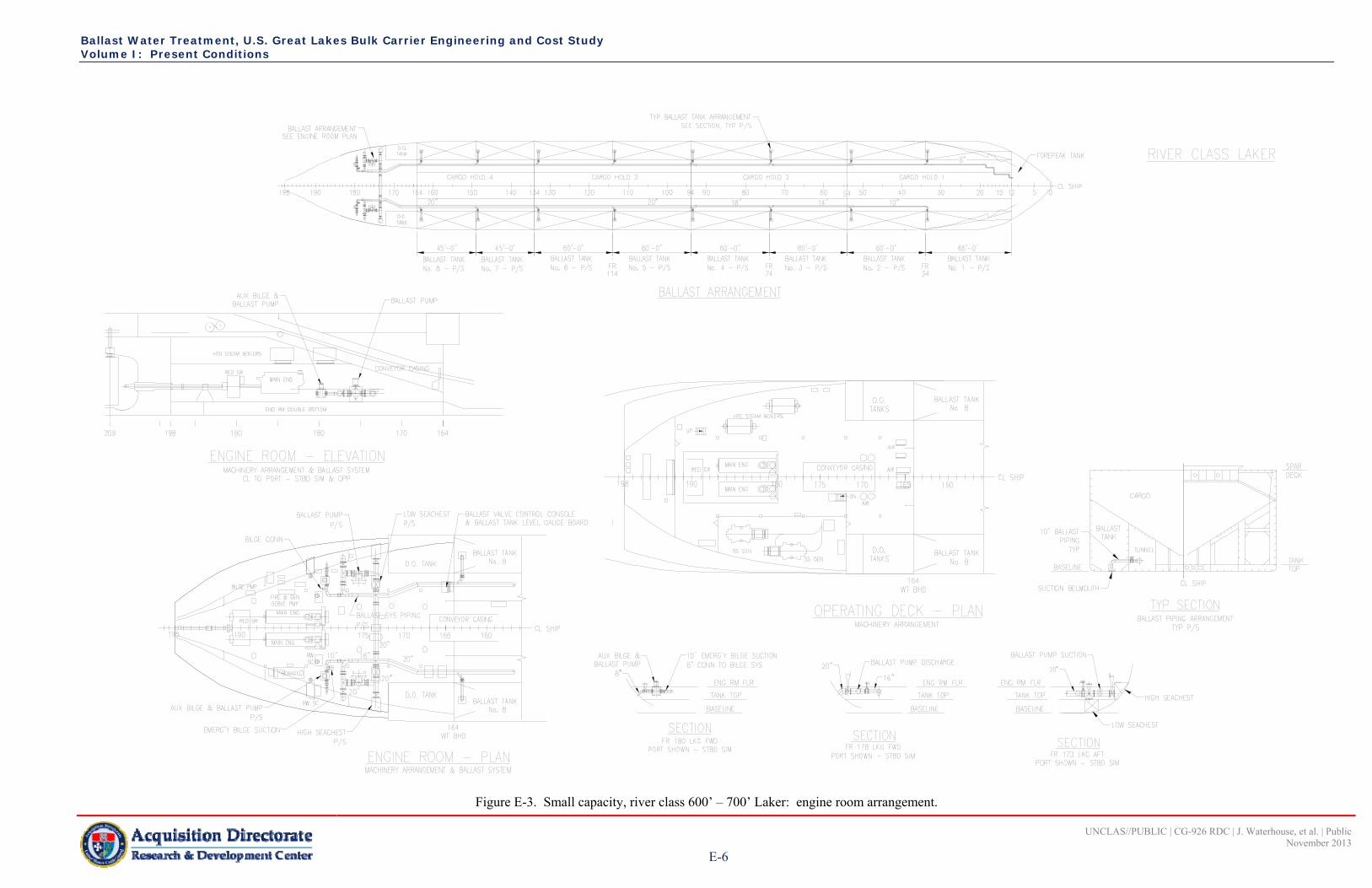
Ballast Water Treatment, U.S. Great Lakes Bulk Carrier Engineering and Cost Study Volume I: Present Conditions
UNCLAS//PUBLIC | CG-926 RDC | J. Waterhouse, et al. | Public November 2013
E-6
Figure E-3. Small capacity, river class 600’ – 700’ Laker: engine room arrangement.

Ballast Water Treatment, U.S. Great Lakes Bulk Carrier Engineering and Cost Study Volume I: Present Conditions
UNCLAS//PUBLIC | CG-926 RDC | J. Waterhouse, et al. | Public November 2013
E-7
Figure E-4. Small capacity, river class 600’ – 700’ Laker: ballast diagram.

Ballast Water Treatment, U.S. Great Lakes Bulk Carrier Engineering and Cost Study Volume I: Present Conditions
UNCLAS//PUBLIC | CG-926 RDC | J. Waterhouse, et al. | Public November 2013
E-8
This page intentionally left blank.