bagasse as a non-conventional source of … as a non-conventional source of energy ... converting...
TRANSCRIPT
International Journal of Advance Research In Science And Engineering http://www.ijarse.com
IJARSE, Vol. No.3, Issue No.4, April 2014 ISSN-2319-8354(E)
121 | P a g e
www.ijarse.com
BAGASSE AS A NON-CONVENTIONAL SOURCE OF
ENERGY
1Dharmendra D. Sapariya,
2Prof. Nilesh R. Sheth
1M-Tech Student of Energy engineering, Department of Mechanical engineering
Gujarat technical University GEC Valsad, Gujarat, (India)
2Assistant
Professor at Department of Energy engineering,
Mechanical engineering GEC Valsad, GTU, (India)
ABSTRACT
Every year millions of tons of agricultural wastes are generated which are either destroyed or burnt inefficiently in
loose form causing air pollution. These wastes can be recycled & can provide a renewable source of energy by
converting biomass waste into different form of energy sources. This recycled fuel is beneficial for the environment
as it conserves natural resources. For this the biomass is the main renewable energy resource.
In this paper the raw material including bagasse as biomass. Bagasse is the crushed outer stalk material formed
after the juice is squeezed from sugar cane, in sugar mills. Bagasse characteristics vary in composition; consistency,
etc. were densified into briquettes at high temperature and pressure using different technologies. We discuss the
various advantages, factors that affecting the biomass briquetting and comparison between coal and bagasse
briquetting. The details of the study were highlighted in this paper.
Keywords: Biomass, Bagasse, Briquetting, Potential, Process, Technologies, Sugarcane
I. INTRODUCTION
Many of the developing countries produce huge quantities of agro residues but they are used inefficiently causing
extensive pollution to the environment. The major residues are bagasse as sugarcane production waste, rice husk,
coffee husk, coir pith, jute sticks, groundnut shells, mustard stalks and cotton stalks. [1,2] India is the second biggest
sugarcane growing country in the World, only behind Brazil. Pondicherry has many sugarcane plantations of its
own, and surrounding Tamil Nadu is the biggest sugarcane growing states in the India. [3]
Sugar industry is the second largest agro based industry in India after textile. About 5 crores of sugarcane farmers,
their dependents and large mass of labourers are involved in sugarcane cultivation, harvesting and ancillary
activities. This constitutes 7.5% of rural population. Dry leaves, left in field after harvest of sugarcane, are called
trash. On an average, a hectare of sugarcane generates about 10 tonnes of trash. Because it has no value as cattle
fodder, and because it also resists decomposition, the trash is burnt in situ, in order to clear the field for the next
crop. The main waste product of sugarcane production is a material known as bagasse. Bagasse is the fibrous residue
that remains in large quantities upon the crushing of sugarcane to remove the sugar juices.
1 Ton sugarcane = 300 Kg of bagasse
International Journal of Advance Research In Science And Engineering http://www.ijarse.com
IJARSE, Vol. No.3, Issue No.4, April 2014 ISSN-2319-8354(E)
122 | P a g e
www.ijarse.com
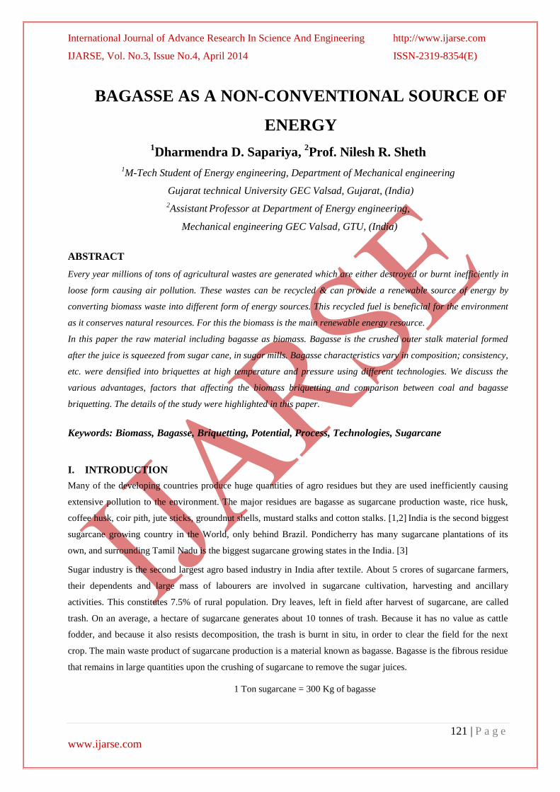
Bagasse pith is usually removed in a process known as “moist de-pithing’ in the sugar factory itself. Following table
indicate top most sugar factory in terms of sugar crushing across the south Gujarat. [2]
Table 1.1: Sugercane factories at south Gujarat[2]
Fig 1.1 Sugar Crop Distribution Areas on the Indian Map Fig. 1.2 Gujarat Sugar Industries Map
II. ADVANTAGES AND DISADVANTAGES OF BAGASSE BRIQUETTING
2.1 Briquetting technique is densification of the loose biomass; this is achieved by subjecting the biomass to heavy
mechanical pressure to form compact cylindrical form known as briquettes. Owing to high moisture content direct
burning of loose bagasse in conventional grates is associated with very low thermal efficiency and widespread air
pollution. The conversion efficiencies are as low as 40% with particulate emissions in the flue gases in excess of
3000 mg/ Nm³ In addition, a large percentage of unburnt carbonaceous ash has to be disposed off.
Fuel Density
g/cm3
Calorific value
Kcal/Kg
Ash
content %
Coal 1.3 3800-5300 20-40
Biomass Briquette from
Bagasse 0.074 4200 4.0
Saw dust 1.7 4600 0.7
Ground Nutshell 1.05 4750 2.0
Rice husk 1.3 3700 18.0
Saw dust cotton 1.12 4300 8.0
Table 2.1: Comparison Coal and Biomass Characteristics Source
Factory Bardoli Gandvi Madhi Chalthan Maroli Valsad Sayan Mahuva Unai
Sugarcane
crushed(MT) 1954267 1107100 1210012 1105891 243573 265332 1137206 661029 78961
Factory Ganesh Coper Kamrej Pandvai Narmada Vadodara Kodinar Talala
Sugarcane
crushed(MT) 592370 400219 510063 556741 715592 367029 241159 120936

International Journal of Advance Research In Science And Engineering http://www.ijarse.com
IJARSE, Vol. No.3, Issue No.4, April 2014 ISSN-2319-8354(E)
123 | P a g e
www.ijarse.com
2.2 Following are the advantages and disadvantages of bagasse briquetting:
2.2.1 Advantages:
a) High calorific value ranges between 3,500-5,000 Kcal/Kg.
b) Moisture percentage is very less (2-5%) compared to lignite, firewood & coal where it is 25-30%.
c) Economic to users compared to other forms.
d) Briquettes can be produced with a density of 1.2g/cm³ from loose biomass of bulk density 0.1 to 0.2 g/cm³.
e) Easy in handling and storage due to its size.
f) Consistent quality.
2.2.2 Disadvantages:
a) High investment cost and energy consumption input to the process
b) Undesirable combustion characteristics often observed e.g., poor ignitability, smoking, etc.
c) Tendency of briquettes to loosen when exposed to water or even high humidity weather text into it.[1]
III. COMPARISON BETWEEN BAGASSE BASED BRIQUETTE AND COAL
Characteristics Bagasse Bagasse based
Briquette Coal
Calorific Value(CV)X 100 4000 Kcal/Kg 4080 Kcal/Kg 4000 Kcal/Kg
Moisture content(M) 45-55 % by weight 2-5 % by weight 4-6% by weight
Ash Content(A) 2 – 10 % 2 – 10 % 25-30%
Table 3.1 Comparisons of bagasse and coal [4]
Fig. 3.1 Comparison Chart of Bagasse, Bagasse Based Briquette, Coal [4]
IV) FACTORS AFFECTING DENSIFICATION / BRIQUETTING
The factors that greatly influence the densification process and determine briquette quality are:
4.1 Temperature and pressure
a) It was found that the compression strength of densified biomass depended on the temperature at which

International Journal of Advance Research In Science And Engineering http://www.ijarse.com
IJARSE, Vol. No.3, Issue No.4, April 2014 ISSN-2319-8354(E)
124 | P a g e
www.ijarse.com
densification was carried out.
b) Maximum strength was achieved at a temperature around 220°C.
c) It was also found that at a given applied pressure, higher density of the product was obtained at higher
temperature.
4.2 Moisture Content
a) Moisture content has an important role to play as it facilitates heat transfer.
b) Too high moisture causes steam formation and could result into an explosion. - Suitable moisture content
could be of 8-12%.
4.3 Drying
a) Drying depends on factors like initial moisture content, particle size, types of densifier, throughout the process.
4.4 Particle Size and Size reduction
a) The finer the particle size, the easier is the compaction process.
b) Fine particles give a larger surface area for bonding.
c) It should be less that 25% of the densified product.
d) Could be done by means of a hammer mill.
e) Wood or straw may require chopping before hammer mill.
V. BAGASSE BRIQUETTING PROCESS
Briquetting is the process of densification of biomass to produce homogeneous, uniformly sized solid pieces of high
bulk density which can be conveniently used as a fuel. The densification of the biomass can be achieved by any one
of the following methods: (i) Pyrolysed densification using a binder, (ii) Direct densification of biomass using
binders and (iii) Binder-less briquetting.[5]
Depending upon the type of biomass, three processes are generally
required involving the following steps:
5.1 Sieving - Drying - Preheating - Densification - Cooling –Packing
5.2 Sieving - Crushing - Preheating - Densification - Cooling –Packing
5.3 Drying - Crushing - Preheating - Densification - Cooling –Packing
Raw
materialsStorage
Wet
material
Drying GrindingBuffer
storage
Dry Material Powder Material
Powder Material
BriquettingCoolingBriquettePacking
Fig. 5.1 Briquette making processes

International Journal of Advance Research In Science And Engineering http://www.ijarse.com
IJARSE, Vol. No.3, Issue No.4, April 2014 ISSN-2319-8354(E)
125 | P a g e
www.ijarse.com
When sawdust is used, process A is adopted. Process B is for agro- and mill residues which are normally dry. These
materials are coffee husk, rice husk, groundnut shells etc. Process C is for materials like bagasse, coir pith (which
needs sieving), mustard and other cereal stalks.
VI. BIOMASS BRIQUETTING TECHNOLOGIES
Biomass densification represents a set of technologies for the conversion of biomass residues into a convenient fuel.
The technology is also known as briquetting or agglomeration. Depending on the types of equipment used, it could
be categorized into five main types:
a) Piston press densification b) Pelletizing
c) Screw press densification d) Low pressure or manual presses
e) Roll press densification
6.1 Piston press densification
There are two types of piston press 1) the die and punch technology; and 2) hydraulic press. In the die and punch
technology, which is also known as ram and die technology, biomass is punched into a die by a reciprocating ram
with a very high pressure thereby compressing the mass to obtain a compacted product. The standard size of the
briquette produced using this machine is 60 mm, diameter. The power required by a machine of capacity 700 kg/hr
is 25 kW. The hydraulic press process consists of first compacting the biomass in the vertical direction and then
again in the horizontal direction. The standard briquette weight is 5 kg and its dimensions are: 450 mm x 160 mm x
80 mm. The power required is 37 kW for 1800 kg/h of briquetting.[6] This technology can accept raw material with
moisture content up to 22%. The process of oil hydraulics allows a speed of 7 cycles/minute (cpm) against 270 cpm
for the die and punch process. The slowness of operation helps to reduce the wear rate of the parts. The ram moves
approximately 270 times per minute in this process.
Fig. 6.1 Briquettes made from a hydraulic press Fig. 6.2 Briquette made by screw extruder
6.2 Screw press
The compaction ratio of screw presses ranges from 2.5:1 to 6:1 or even more. In this process, the biomass is
extruded continuously by one or more screws through a taper die which is heated externally to reduce the friction.[7]
Here also, due to the application of high pressures, the temperature rises fluidizing the lignin present in the biomass
International Journal of Advance Research In Science And Engineering http://www.ijarse.com
IJARSE, Vol. No.3, Issue No.4, April 2014 ISSN-2319-8354(E)
126 | P a g e
www.ijarse.com
which acts as a binder. The outer surface of the briquettes obtained through this process is carbonized and has a hole
in the centre which promotes better combustion. Standard size of the briquette is 60 mm diameter.
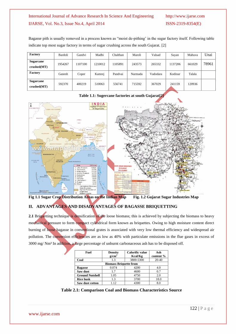
6.3 Roller Press
In a briquetting roller press, the feedstock falls in between two rollers, rotating in opposite directions and is
compacted into pillow-shaped briquettes. Briquetting biomass usually requires a binder. This type of machine is
used for briquetting carbonized biomass to produce charcoal briquettes.
Fig. 6.3 Roller Press For Agglomeration Of Biomass Fig. 6.4 Briquettes Made From A Pellet Mill.
6.4 Pelletizing
Pelletizing is closely related to briquetting except that it uses smaller dies (approximately 30 mm) so that the
smaller products are called pellets. The pelletizer has a number of dies arranged as holes bored on a thick steel disk
or ring and the material is forced into the dies by means of two or three rollers. The two main types of pellet
presses are: flat/disk and ring types. Other types of pelletizing machines include the Punch press and the Cog-
Wheel pelletizer. Pelletizers produce cylindrical briquettes between 5mm and 30mm in diameter and of variable
length. They have good mechanical strength and combustion characteristics. Pellets are suitable as a fuel for
industrial applications where automatic feeding is required. Typically pelletizers can produce up to1000 kg of
pellets per hour but initially require high capital investment and have high energy input requirements.
6.5 Manual Presses and Low pressure Briquetting
There are different types of manual presses used for briquetting biomass feed stocks. They are specifically designed
for the purpose or adapted from existing implements used for other purposes. Manual clay brick making presses are
a good example. They are used both for raw biomass feedstock or charcoal. The main advantages of low-pressure
briquetting are low capital costs, low operating costs and low levels of skill required to operate the technology. Low-
pressure techniques are particularly suitable for briquetting green plant waste such as coir or bagasse (sugar-cane
residue). The wet material is shaped under low pressure in simple block presses or extrusion presses. The resulting
briquette has a higher density than the original material but still requires drying before it can be used. The dried
briquette has little mechanical strength and crumbles easily. The use of a binder is imperative.
International Journal of Advance Research In Science And Engineering http://www.ijarse.com
IJARSE, Vol. No.3, Issue No.4, April 2014 ISSN-2319-8354(E)
127 | P a g e
www.ijarse.com
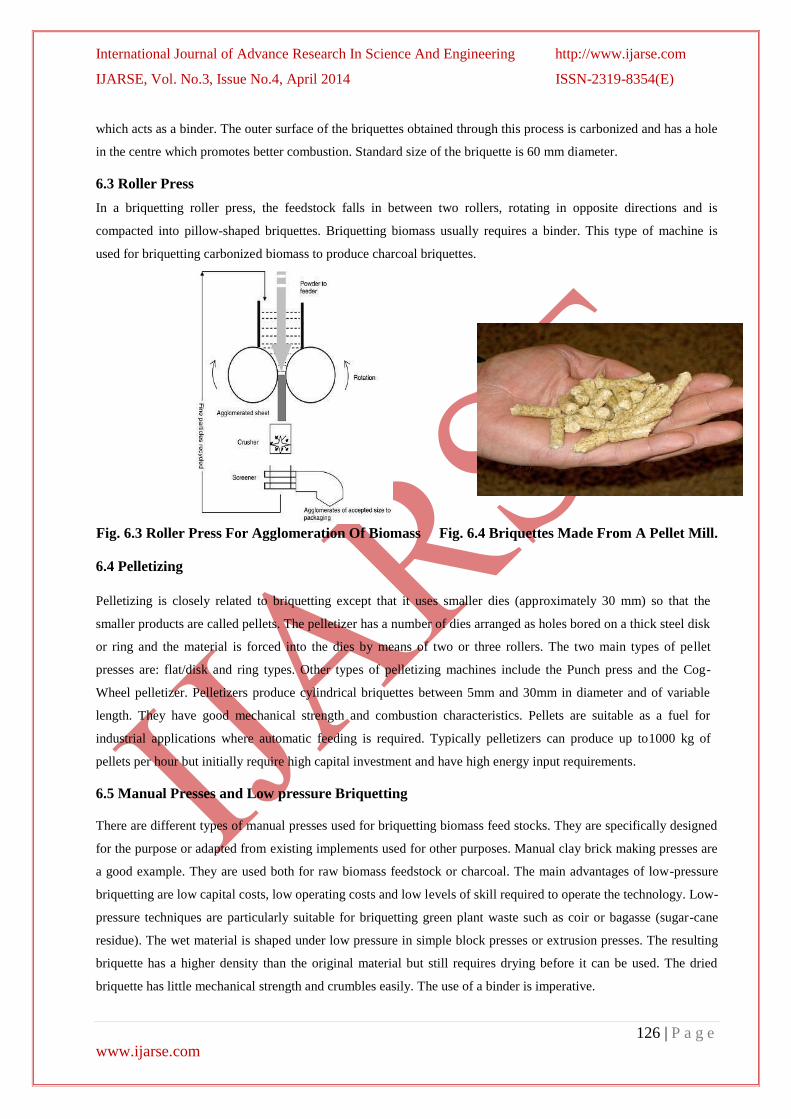
VII. CO-FIRING METHOD OF GENERATION OF HEAT FROM BAGASSE
Co-firing is combustion of two different types of materials at the same time. Two distinct techniques are available to
co-fire bio-fuels in utility boilers:
7.1 Direct co-firing:- Biomass fuels are blended with coal in coal yard and the blend is sent to the firing system
which is seen in Fig.7.1.
Fig. 7.1 Direct Co-Firing System Fig. 7.2 Indirect Co-Firing System
7.2 Indirect co-firing:- The biomass is prepared separately from the coal and injected into the boiler without
impacting the coal delivery process Fig. 7.2. The first approach, in general, is used with less than 5 wt. % co-firing.
[8]
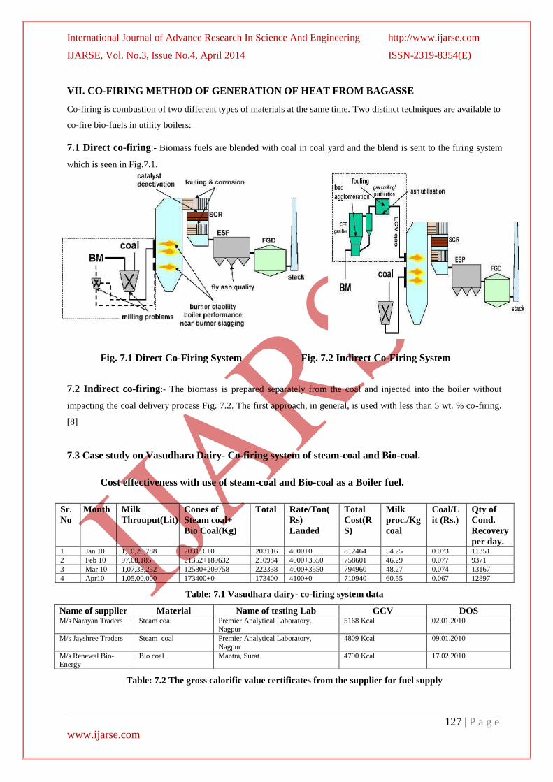
7.3 Case study on Vasudhara Dairy- Co-firing system of steam-coal and Bio-coal.
Cost effectiveness with use of steam-coal and Bio-coal as a Boiler fuel.
Sr.
No
Month Milk
Throuput(Lit)
Cones of
Steam coal+
Bio Coal(Kg)
Total Rate/Ton(
Rs)
Landed
Total
Cost(R
S)
Milk
proc./Kg
coal
Coal/L
it (Rs.)
Qty of
Cond.
Recovery
per day. 1 Jan 10 1,10,20,788 203116+0 203116 4000+0 812464 54.25 0.073 11351
2 Feb 10 97,68,185 21352+189632 210984 4000+3550 758601 46.29 0.077 9371
3 Mar 10 1,07,33,252 12580+209758 222338 4000+3550 794960 48.27 0.074 13167
4 Apr10 1,05,00,000 173400+0 173400 4100+0 710940 60.55 0.067 12897
Table: 7.1 Vasudhara dairy- co-firing system data
Name of supplier Material Name of testing Lab GCV DOS M/s Narayan Traders Steam coal Premier Analytical Laboratory,
Nagpur
5168 Kcal 02.01.2010
M/s Jayshree Traders Steam coal Premier Analytical Laboratory, Nagpur
4809 Kcal 09.01.2010
M/s Renewal Bio-
Energy
Bio coal Mantra, Surat 4790 Kcal 17.02.2010
Table: 7.2 The gross calorific value certificates from the supplier for fuel supply
International Journal of Advance Research In Science And Engineering http://www.ijarse.com
IJARSE, Vol. No.3, Issue No.4, April 2014 ISSN-2319-8354(E)
128 | P a g e
www.ijarse.com
As per trial results
1) The consumption ratio of steam coal: Biocoal = 1 : 1.19
2) The GCV comparison of steam coal : Biocoal = 5100 : 4700 (1 : 0.92)
3) The Rate comparison of steam coal : Biocoal = 4100 : 3550 (1 : 0.86)
Example of trial during April 2010
Sr. No. Parameter Steam Coal (Actual ) Biocoal(Expected)
1 Consumption 173.400 MT 206.346 MT
2 Rate 4100/ Ton 3550/Ton
3 GCV 5100 4700
4 Total Cost Rs. 7,10,940 Rs. 7,32,528
5 Saving Rs. 21,588.30
Table: 7.3 Boiler trials during April 2010
SR NO. Rate different Steam coal Biocoal Saving
1 550 Economic Costly 21588
2 655 At par At par 0
3 700 Costly Economic 9363
4 800 Costly Economic 29998
5 900 Costly Economic 50632
6 1000 Costly Economic 71267
Table: 7.4 Rate different of steam coal & biocoal with respect to GCV
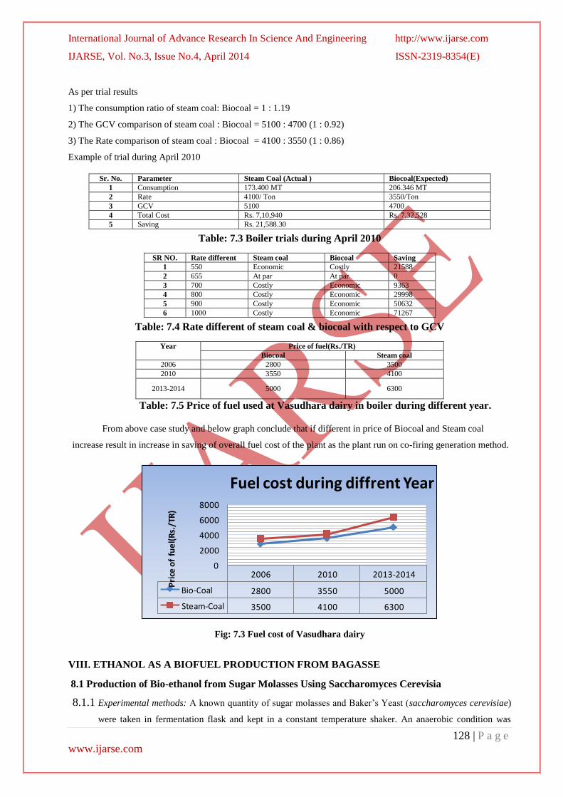
Year Price of fuel(Rs./TR)
Biocoal Steam coal
2006 2800 3500
2010 3550 4100
2013-2014 5000 6300
Table: 7.5 Price of fuel used at Vasudhara dairy in boiler during different year.
From above case study and below graph conclude that if different in price of Biocoal and Steam coal
increase result in increase in saving of overall fuel cost of the plant as the plant run on co-firing generation method.
2006 2010 2013-2014
Bio-Coal 2800 3550 5000
Steam-Coal 3500 4100 6300
0
2000
4000
6000
8000
Pri
ce o
f fu
el(
Rs.
/TR
)
Fuel cost during diffrent Year
Fig: 7.3 Fuel cost of Vasudhara dairy
VIII. ETHANOL AS A BIOFUEL PRODUCTION FROM BAGASSE
8.1 Production of Bio-ethanol from Sugar Molasses Using Saccharomyces Cerevisia
8.1.1 Experimental methods: A known quantity of sugar molasses and Baker’s Yeast (saccharomyces cerevisiae)
were taken in fermentation flask and kept in a constant temperature shaker. An anaerobic condition was
International Journal of Advance Research In Science And Engineering http://www.ijarse.com
IJARSE, Vol. No.3, Issue No.4, April 2014 ISSN-2319-8354(E)
129 | P a g e
www.ijarse.com
maintained for four days and during this period, the strain converts sugar into bio-ethanol with the evolution
of CO2. A known fermented sample was collected for every 12 h interval. The same procedure was repeated
to optimize the parameters such as pH, Temperature, substrate concentration and yeast concentration.
8.1.2 Identification of bio-ethanol: About 5 to 10 ml fermented sample was taken and pinch a of potassium
dichromate and a few drop of H2SO4 were added. The colour of the sample turns from pink to green which
indicates the presence of bio-ethanol.
8.1.3 Determination of sugar concentration: 100 ml of distilled water and mixed with 5 ml of conc. HCL acid and
is heated at 70 ˚C for a period of 10 min. The obtained sample was neutralized by adding NaOH and it was
prepared to 1000 ml and taken into burette solution. The 5 ml of Fehling A and 5 ml of Fehling B were taken
and mixed with 10 to 15 ml of distilled water in a conical flask and Methylene blue indicator was added. The
conical flask solution was titrated with burette solution in boiling conditions until disappearance of blue
colour. The sugar concentration was calculated by using the formula given below.
8.1.4 Determination of ethanol concentration and pH: The sample was fermented to different pH values between
1.0 and 8.0 to obtain maximum yield of bio-ethanol by adding lime or sulphuric acid. The samples were kept
in anaerobic condition for a period of four days and the fermented solution was analyzed for every 12 h
intervals.
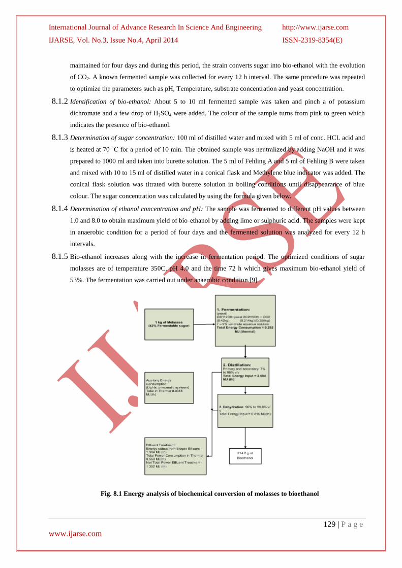
8.1.5 Bio-ethanol increases along with the increase in fermentation period. The optimized conditions of sugar
molasses are of temperature 350C, pH 4.0 and the time 72 h which gives maximum bio-ethanol yield of
53%. The fermentation was carried out under anaerobic condition.[9]
Fig. 8.1 Energy analysis of biochemical conversion of molasses to bioethanol

International Journal of Advance Research In Science And Engineering http://www.ijarse.com
IJARSE, Vol. No.3, Issue No.4, April 2014 ISSN-2319-8354(E)
130 | P a g e
www.ijarse.com
IX. GASSES FUEL GENERATED FROM BAGASSE
Biogas is a mixture of 60–75% CH4 and 40–25% CO2, can be produced from a variety of organic compound through
a complex anaerobic digestion processes, and can be upgraded by further steps to bio-methane. It has a calorific
value of about 20–25 MJ/m3 which can be upgraded by removing the carbon dioxide. The produced slurry as
digester residue has a potential to be used as fertilizer and soil conditioner. Biogas digester can be operated in
different range of temperature as thermophilic system operated at high temperature (50-70˚C), mesophilic system,
moderate temperature ranging between 35-40˚C and psychrophilic system that operate at temperature range of 15-
25˚C. Operating temperature is very detrimental factor to obtain high gas conversion efficiency with short hydraulic
retention time, it takes up to months in a very low temperature. [9]
Biomass
Gasification TorrefactionElectricity and
heat
Products:
- Hydrogen
- Carbon monoxide
- Carbon dioxide
- Methane
- Acetylene
- Ethylene
- Benzene, Toluene, Xylene
- Light tars
- Heavy tars
- Ammonia
- Water
Tar Distillation
Light tarsHeavy tars Solvents Fertilizer
Cryogenic
distrillation
CO2
removal
Gaseous fuels
- Methane
- Synthetic Natural
Gas
Transportation fuels
- Fischer- Tropsch diesel
- Hydrogen
- Methane
Biosyngas
Fig. 9.1 Products from gasification process
9.1 Bagasse gasification in gasifier
The gasification of biomass is a thermal treatment, which results in a high production of gaseous products and small
quantities of char and ash. It is a well-known technology that can be classified depending on the gasifying agent: air,
steam, steam–oxygen, air–steam, oxygen-enriched air, etc. Gasification is carried out at high temperatures in order
to optimize the gas production. The resulting gas, known as producer gas, is a mixture of carbon monoxide,
hydrogen and methane, together with carbon dioxide and nitrogen.
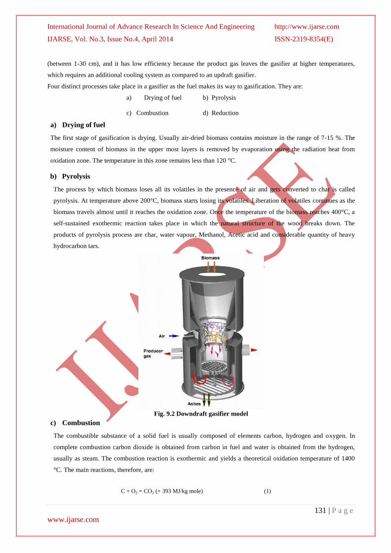
9.2 Downdraft gasifier model
Downdraft gasifiers are very similar to updraft gasifiers (Fig. 9.2), except that the feedstock and oxidizer in
downdraft gasifiers both enter from the top of the gasifier. The gas passes though the hot zone combusting the tars
and leaving the reactor from the bottom. Some of the advantages of this design are that it has a fairly simple design
and is low cost, and it produces a relatively cleaner gas with very low tar formation. Some of the disadvantages are
that the system requires low moisture and ash feedstock, can only use feedstocks within a limited particle size range
International Journal of Advance Research In Science And Engineering http://www.ijarse.com
IJARSE, Vol. No.3, Issue No.4, April 2014 ISSN-2319-8354(E)
131 | P a g e
www.ijarse.com
(between 1-30 cm), and it has low efficiency because the product gas leaves the gasifier at higher temperatures,
which requires an additional cooling system as compared to an updraft gasifier.
Four distinct processes take place in a gasifier as the fuel makes its way to gasification. They are:
a) Drying of fuel b) Pyrolysis
c) Combustion d) Reduction
a) Drying of fuel
The first stage of gasification is drying. Usually air-dried biomass contains moisture in the range of 7-15 %. The
moisture content of biomass in the upper most layers is removed by evaporation using the radiation heat from
oxidation zone. The temperature in this zone remains less than 120 °C.
b) Pyrolysis
The process by which biomass loses all its volatiles in the presence of air and gets converted to char is called
pyrolysis. At temperature above 200°C, biomass starts losing its volatiles. Liberation of volatiles continues as the
biomass travels almost until it reaches the oxidation zone. Once the temperature of the biomass reaches 400°C, a
self-sustained exothermic reaction takes place in which the natural structure of the wood breaks down. The
products of pyrolysis process are char, water vapour, Methanol, Acetic acid and considerable quantity of heavy
hydrocarbon tars.
Fig. 9.2 Downdraft gasifier model
c) Combustion
The combustible substance of a solid fuel is usually composed of elements carbon, hydrogen and oxygen. In
complete combustion carbon dioxide is obtained from carbon in fuel and water is obtained from the hydrogen,
usually as steam. The combustion reaction is exothermic and yields a theoretical oxidation temperature of 1400
°C. The main reactions, therefore, are:
C + O2 = CO2 (+ 393 MJ/kg mole) (1)
International Journal of Advance Research In Science And Engineering http://www.ijarse.com
IJARSE, Vol. No.3, Issue No.4, April 2014 ISSN-2319-8354(E)
132 | P a g e
www.ijarse.com
2H2 + O2 = 2H2 O (- 242 MJ/kg mole) (2)
d) Reduction
The products of partial combustion (water, carbon dioxide and un-combusted partially cracked pyrolysis products)
now pass through a red-hot charcoal bed where the following reduction reactions take place:
C + CO2 = 2CO (- 164.9 MJ/kg mole) (3)
C + H2O = CO + H2 (- 122.6 MJ/kg mole) (4)
CO + H2O = CO + H2 (+ 42 MJ/kg mole) (5)
C + 2H2 = CH4 (+ 75 MJ/kg mole) (6)
CO2 + H2 = CO + H2O (- 42.3 MJ/kg mole) (7)
Reactions (3) and (4) are main reduction reactions and being endothermic have the capability of reducing gas
temperature. Consequently the temperatures in the reduction zone are normally 800-1000˚C. Lower the reduction
zone temperature (~ 700-800˚C), lower is the calorific value of gas.[10]
X. CONCLUSION
1. By the use of bagasse as a fuel in three different form of energy result in a sustainable production and power
generation can solve the vital issues of atmospheric pollution, energy crisis, wasteland development, rural
employment generation and power transmission losses. The energy requirement of any countries can be fulfilled by
different form of bagasse without emission of GHG and pollutant substance in the atmosphere. Bagasse provides
both, thermal energy as well as reduction for oxides. It is renewable, widely available carbon-neutral and has the
potential to provide significant employment in the rural areas. Also reduce dependency on other countries for energy
sources requirement.
2. From this paper can be said that Bagasse is a Non-conventional source of energy.
XI. ACKNOWLEDGEMENT
Thanks to my respected guide Prof. Nilesh R. Sheth and Prof. Vijay K. Patel (External guide) for his valuable time
and constant help given to me.
I would also like to thank Prof. S. V. Damania PG in charge, Mechanical Engineering Department, Government
Engineering College, Valsad. Who has always been prepared to offer me help at any time, in spite of having busy
schedule. I am also thankful to all the faculty members of mechanical department who gave me inspiration
and helped me.
I would also like to thank Dr. S A Channiwala, Mechanical Engineering Department, SVNIT Surat. Prof. J.M.Patel
LD College of engineering
International Journal of Advance Research In Science And Engineering http://www.ijarse.com
IJARSE, Vol. No.3, Issue No.4, April 2014 ISSN-2319-8354(E)
133 | P a g e
www.ijarse.com
I would also like to thank Mr. Nimesh patel, owner of Hemali Bioenergy, Valsad and Mr. Rajeshbhai, Partner of
Soham Energy, GIDC Surat Who gave permission to visit their industries which help me to improve my knowledge
regarding my project.
References
1. P.D. Grover, S.K. Mishra, “Utilisation of Bagasse Briquettes as Alternative Source of Fuel” Ministry of State for
Environmental Affairs Egyptian Environmental Affairs April 1996.
2. Chesta Tiwari, “Producing fuel briquette from sugarcane waste”, EWB-UK National Research & Education
Conference 2011 „Our Global Future‟ 4th
March 2011
3. P.D. Grover, S.K. Mishra, „„Biomass Briquetting: Technology and Practices‟‟Food and Agriculture Organization
of the United Nations, Bangkok, April 1996.
4. Filiz Karaosmanoglu, Biobriquetting of rapeseed cake, Energy Sources 22(3), 2000, 257-267
5. P.D.Grover, S.K Mishra,., Regional Wood Energy Development Programme in India, Proc. International
Workshop on Biomass Briquetting, New Delhi, April 1995.
6. A Koopmans, Proc. of the International Workshop on Biomass briquetting 23 Bangkok, 1999.
8. R. Saidur, E.A.Abdelaziz, A.Demirbas, M.S.Hossain, S.Mekhilef, “A review on biomass as a fuel for boilers”
Renewable and sustainable Energy Review 15 (2011) 2262-2289
9. Shanmugam Periyasamy, Sivakumar Venkatachalam, Sridhar Ramasamy, Venkatesan Srinivasan, “Production
of Bio-ethanol from Sugar Molasses” Modern applied science Vol.3 August 2009.
10. Energy Conservation Vol. 3 “Energy Efficiency in thermal system” by V.K.Gaudani, IECC press, New Delhi