b80 concrete work for bridges - roads and maritime services · sealed curing amended to include...
TRANSCRIPT

ROADS AND MARITIME SERVICES (RMS)
QA SPECIFICATION B80
CONCRETE WORK FOR BRIDGES
NOTICE
This document is a Roads and Maritime Services QA Specification. It has been developed for use with roadworks and bridgeworks contracts let by Roads and Maritime Services or by local councils in NSW. It is not suitable for any other purpose and must not be used for any other purpose or in any other context.
Copyright in this document belongs to Roads and Maritime Services.
REVISION REGISTER
Ed/Rev Number
Clause Number Description of Revision Authorised
By Date
Ed 6/Rev 0 All Text revised to direct imperative style. Minor reformatting and editing for clarity.
GM, IC 04.04.12
Various Some clauses and tables re-numbered. “Cast in-situ” replaced with “cast-in-place”. “Component” and “element” changed to “member”.
1.3 Definitions: “Portland cements” replaced with “General Purpose cements”. Sealed curing amended to include plastic wrapping. Definition of self-compacting concrete added. Heat accelerated curing amended.
2.2 Name of “Cement & Concrete Users Review Group (CCURG)” updated to “Australian Technical Infrastructure Committee (ATIC)”. Requirement for taking of initial 5 kg cement sample deleted.
2.3.1 Use of air entraining agents clarified.
2.4.1 “Cl. 2.4” inserted in first paragraph. “severe exposure” classification replaced by “exposure classification C”.
2.4.3 Provisions for manufactured sand added.
Table B80.2 Tolerance on 6.7 mm sieve for 20 mm nominal size aggregate added.
2.5 Clause clarified.
Table B80.4 Amended to accord with revised RMS T363.
2.6 Clause on soluble salts separated into 2 sub-clauses and clarified.
Edition 6 / Revision 7 ROADS AND MARITIME SERVICES November 2017

Ed/Rev Number
Clause Number Description of Revision Authorised
By Date
Ed 6/Rev 0 (cont’d)
3.2 Requirements for durability extensively modified. Concrete Durability Plan option included.
Table B80.6 New table on durability requirements added.
3.2.1 Clause deleted. Contents moved to Cl. 3.4.1.
3.2.2 Clause deleted. Contents moved to Cl. 3.4.2.
3.3 New clause for prevention of adverse effects added for clarity.
3.4 New clause for curing added.
3.4.1 Notes from Table B80.7 incorporated as second paragraph and reworded. New provisions for curing added.
Table B80.7 Previous Table B80.6. Heading amended. Deleted columns for “Minimum cement content” and “Maximum water/cement ratio” moved to new Table B80.6.
3.4.2 Sorptivity test now used to assess curing only, not durability.
3.5 Limits for maximum compressive strength included. Deck target strength amended.
3.6 Initial slump value for HRWR admixture removed. Maximum slump changed to 180 mm. “Unless otherwise approved by the Principal” added in last paragraph.
Table B80.8 Shrinkage limits for self-compacting concrete, slag-blended cements and exposure classification C without corrosion inhibitor added. Note clarified for precast members.
3.8.1 Additional conformance criteria for trial mix added in second paragraph. Tolerances clarified. Hold Point references renumbered. Additional requirement for approved concrete mix added in last paragraph.
3.8.2 fc.max added to mix design submission. Taking of initial slumps deleted for concrete containing HRWR. Mixing time prior to addition of HRWR admixture deleted. Test result for chloride resistance added.
3.9 Permissible admixture variation changed to 20%.
4.2 Aggregates to be stored SSD or wetter.
ii

Ed/Rev Number
Clause Number Description of Revision Authorised
By Date
Ed 6/Rev 0 (cont’d)
4.3.4 Additional items to be shown on delivery docket inserted, for better monitoring of water content.
4.3.5 Mixing time after addition of admixture reduced from 5 to 3 minutes.
4.4 Clause heading amended. Paragraph order changed. Time for checking of slumps changed from 30 to 45 minutes of adding cement or at discharge. Clauses dealing with taking of initial slumps for concrete with HRWR deleted. Additional criteria to control uniformity of concrete included in 4th paragraph. New clause on water/cement ratio added.
4.5 Mixing after water addition amended. Tolerances clarified.
5.2.3 Formwork design requirements amended.
5.2.4 Formwork submission requirements amended. Hold Point amended.
5.3.2 Term “test panel” changed to “test member” and requirements amended.
5.5 Construction joints for columns now to be at least 100 mm above pilecap/footing level.
5.6 “When left in place” added to 4th paragraph regarding use of expanded metal mesh.
5.7 Formwork erection requirements clarified.
5.8 Tolerances for slipformed parapets deleted in Table B80.11.
5.10 Texture and colour added to requirement for uniformity in concrete repair.
6.4.2 Lapped splices amended to accord with AS 3600:2009. Slipformed parapets deleted.
6.4.3 Link to list of RMS approved mechanical splices added.
6.7.2 Extensively revised. Requirements for aspros amended. Use of plastic and strip bar chairs limited.
6.7.3 Witness Point for cages added.
7.1 Concreting training by Principal deleted.
7.3 Witness Point amended and changed to Hold Point for precast members. Concrete Supervisor to hold Grey Card.
iii

Ed/Rev Number
Clause Number Description of Revision Authorised
By Date
Ed 6/Rev 0 7.4.3 Compaction requirements amended.
(cont’d) 7.5 Cooling and covering measures on hot days after concreting added.
7.8 Concrete placement in water amended.
7.11.2.1 Deck screeding requirements amended.
7.11.2.5 Concrete wetting clarified. Use of finishing aids clarified. Additional option for concrete finishing added in bullet point (a).
7.12.1 Curing clarified.
7.12.2 Wet curing clarified.
7.12.3.2 Additional condition on application of curing compounds added in tenth paragraph.
Table B80.18
Lower limit on non-volatile content for all curing compounds added.
7.12.3.3 Sealed curing using plastic wrapping added.
7.12.4.1 Presetting period amended to include concrete maturity. Maximum steam curing temperature now 70°C for all exposure classifications.
7.13 Slipformed barriers not permitted.
7.14 Preparation of deck joint blockout clarified.
7.15 Completion of deck curing required before traffic allowed.
8.1 Taking of cores limited. Restoration of core holes clarified.
8.2 Concrete with representative compressive strength exceeding 100 MPa deemed nonconforming added.
Annex A2 Items added for self-compacting concrete and deck screeding using power screeds and height pins. Items rearranged in sequence. Slipformed barriers deleted.
Annex B1.2 Additional compliance criteria for concrete compressive strength added in first paragraph.
Annex C New Witness Point for reinforcement cages added. Witness Point for precast members changed to Hold Point.
Annex D New item for concrete mix designs added with other minor amendments.
iv
Ed/Rev Number
Clause Number Description of Revision Authorised
By Date
Ed 6/Rev 0 (cont’d)
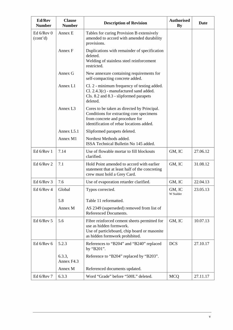
Annex E Tables for curing Provision B extensively amended to accord with amended durability provisions.
Annex F Duplications with remainder of specification deleted. Welding of stainless steel reinforcement restricted.
Annex G New annexure containing requirements for self-compacting concrete added.
Annex L1 Cl. 2 - minimum frequency of testing added. Cl. 2.4.3(c) - manufactured sand added. Cls. 8.2 and 8.3 - slipformed parapets deleted.
Annex L3 Cores to be taken as directed by Principal. Conditions for extracting core specimens from concrete and procedure for identification of rebar locations added.
Annex L5.1 Slipformed parapets deleted.
Annex M1 Nordtest Methods added. ISSA Technical Bulletin No 145 added.
Ed 6/Rev 1 7.14 Use of flowable mortar to fill blockouts clarified.
GM, IC 27.06.12
Ed 6/Rev 2 7.1 Hold Point amended to accord with earlier statement that at least half of the concreting crew must hold a Grey Card.
GM, IC 31.08.12
Ed 6/Rev 3 7.6 Use of evaporation retarder clarified. GM, IC 22.04.13
Ed 6/Rev 4 Global Typos corrected. GM, IC W Stalder
23.05.13
5.8 Table 11 reformatted.
Annex M AS 2349 (superseded) removed from list of Referenced Documents.
Ed 6/Rev 5 5.6 Fibre reinforced cement sheets permitted for use as hidden formwork. Use of particleboard, chip board or masonite as hidden formwork prohibited.
GM, IC 10.07.13
Ed 6/Rev 6 5.2.3 References to “B204” and “B240” replaced by “B201”.
DCS 27.10.17
6.3.3, Annex F4.3
Reference to “B204” replaced by “B203”.
Annex M Referenced documents updated.
Ed 6/Rev 7 6.3.3 Word “Grade” before “500L” deleted. MCQ 27.11.17
v


QA SPECIFICATION B80
CONCRETE WORK FOR BRIDGES Copyright – Roads and Maritime Services
IC-QA-B80
VERSION FOR: DATE:
Edition 6 / Revision 7 ROADS AND MARITIME SERVICES November 2017


Concrete Work for Bridges B80
CONTENTS
CLAUSE PAGE
FOREWORD ............................................................................................................................................. IV RMS Copyright and Use of this Document .................................................................................. iv Revisions to Previous Version ...................................................................................................... iv Project Specific Changes .............................................................................................................. iv
1 GENERAL ........................................................................................................................................ 1 1.1 Scope .............................................................................................................................. 1 1.2 Structure of the Specification ......................................................................................... 1 1.3 Definitions ...................................................................................................................... 2
2 MATERIALS FOR CONCRETE, CEMENT MORTAR AND GROUT ....................................................... 3 2.1 General ........................................................................................................................... 3 2.2 Cement ............................................................................................................................ 3 2.3 Admixtures ..................................................................................................................... 4 2.4 Aggregates ...................................................................................................................... 4 2.5 Alkali-Aggregate Reaction (AAR) ................................................................................. 6 2.6 Soluble Salts ................................................................................................................... 7
3 DESIGN OF CONCRETE MIXES ........................................................................................................ 8 3.1 General ........................................................................................................................... 8 3.2 Design for Durability...................................................................................................... 8 3.3 Prevention of Adverse Effects ...................................................................................... 11 3.4 Curing ........................................................................................................................... 12 3.5 Target Strength for Mix Design ................................................................................... 13 3.6 Limitations on Slump ................................................................................................... 13 3.7 Limitations on Shrinkage ............................................................................................. 13 3.8 Nominated Mixes ......................................................................................................... 14 3.9 Variations to Nominated Mixes ................................................................................... 16
4 SUPPLY AND DELIVERY OF CONCRETE ........................................................................................ 16 4.1 General ......................................................................................................................... 16 4.2 Moisture Content of Aggregates .................................................................................. 17 4.3 Additional Requirements for Mixing ........................................................................... 17 4.4 Slump and Water/Cement Ratio Tolerances ................................................................ 19 4.5 Addition of Water to a Mixed Batch ............................................................................ 19 4.6 Temperature at Point of Delivery ................................................................................. 19 4.7 Presence of Corrosion Inhibitor in Fresh Concrete ...................................................... 19
5 FORMWORK .................................................................................................................................. 20 5.1 General ......................................................................................................................... 20 5.2 Formwork Design, Documentation and Certification .................................................. 20 5.3 Surface Finish ............................................................................................................... 22 5.4 Site-related Requirements ............................................................................................ 23 5.5 Construction Joints ....................................................................................................... 23 5.6 Materials for Formwork Surfaces ................................................................................ 24 5.7 Erection of Formwork .................................................................................................. 24 5.8 Tolerances .................................................................................................................... 25 5.9 Removal of Formwork.................................................................................................. 28 5.10 Repairs to Formed Surfaces ......................................................................................... 28
Ed 6 / Rev 7 i

B80 Concrete Work for Bridges
6 SUPPLY AND FIXING OF STEEL REINFORCEMENT AND EMBEDMENTS ......................................... 28 6.1 Quality Management System Requirements................................................................. 29 6.2 Materials ....................................................................................................................... 29 6.3 Fabrication, Bending and Welding ............................................................................... 29 6.4 Splicing ......................................................................................................................... 30 6.5 Storage .......................................................................................................................... 32 6.6 Surface Condition ......................................................................................................... 32 6.7 Placing and Fixing of Reinforcement and Embedments .............................................. 32 6.8 Cover............................................................................................................................. 34 6.9 Tolerances ..................................................................................................................... 34
7 PLACING, COMPACTING, FINISHING AND CURING OF CONCRETE ................................................ 35 7.1 General .......................................................................................................................... 35 7.2 Concrete Cracking ........................................................................................................ 36 7.3 Certification by Contractor ........................................................................................... 37 7.4 Concrete Placement and Compaction - Basic Requirements ....................................... 38 7.5 Temperature and Rain .................................................................................................. 39 7.6 Control of Moisture Loss .............................................................................................. 39 7.7 Placing Outside Daylight Hours ................................................................................... 39 7.8 Placing in Water ........................................................................................................... 40 7.9 Preparation of Surface of Construction Joints .............................................................. 42 7.10 Additional Requirements for Voided Slab Construction ............................................. 42 7.11 Screeding and Finishing of Unformed Surfaces ........................................................... 42 7.12 Curing ........................................................................................................................... 44 7.13 Slipformed Barriers ...................................................................................................... 47 7.14 Concreting of Deck Joint Blockouts ............................................................................. 47 7.15 Early Trafficking of Bridge Decks ............................................................................... 47
8 PROPERTIES OF HARDENED CONCRETE ....................................................................................... 48 8.1 General .......................................................................................................................... 48 8.2 Compressive Strength ................................................................................................... 48 8.3 Compaction ................................................................................................................... 49 8.4 Cover............................................................................................................................. 49
ANNEXURE B80/A – PROJECT SPECIFIC REQUIREMENTS ...................................................................... 50 A1 Members in Exposure Classification U ........................................................................ 50 A2 Bridge Members for Which Self-Compacting Concrete is Permitted (Job Specific) .. 51 A3 Formwork Category C (Job Specific) ........................................................................... 51 A4 Surface Finish Requirements (Job Specific) ................................................................ 51 A5 Bridge Decks for Which Screeding Using Vibrating Power Screeds and Height Pins is
Permitted (Job Specific) ............................................................................................... 51
ANNEXURE B80/B – RESOLUTION OF NONCONFORMITIES .................................................................... 52 B1 Compressive Strength ................................................................................................... 52
ANNEXURE B80/C – SCHEDULES OF HOLD POINTS, WITNESS POINTS AND IDENTIFIED RECORDS ....... 53 C1 Schedule of Hold Points and Witness Points ............................................................... 53 C2 Schedule of Identified Records..................................................................................... 53
ANNEXURE B80/D – PLANNING DOCUMENTS ........................................................................................ 54
ANNEXURE B80/E – CURING PROVISION B ............................................................................................ 55
ANNEXURE B80/F – STAINLESS STEEL REINFORCEMENT ...................................................................... 57
ii Ed 6 / Rev 7
Concrete Work for Bridges B80
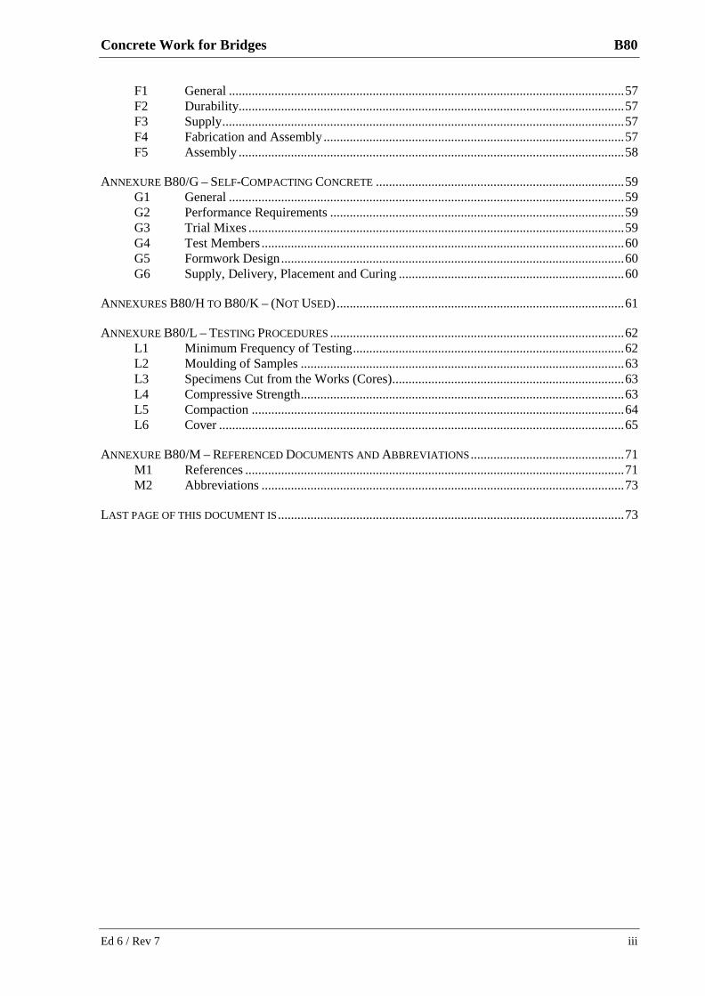
F1 General ......................................................................................................................... 57 F2 Durability...................................................................................................................... 57 F3 Supply ........................................................................................................................... 57 F4 Fabrication and Assembly ............................................................................................ 57 F5 Assembly ...................................................................................................................... 58
ANNEXURE B80/G – SELF-COMPACTING CONCRETE ............................................................................ 59 G1 General ......................................................................................................................... 59 G2 Performance Requirements .......................................................................................... 59 G3 Trial Mixes ................................................................................................................... 59 G4 Test Members ............................................................................................................... 60 G5 Formwork Design ......................................................................................................... 60 G6 Supply, Delivery, Placement and Curing ..................................................................... 60
ANNEXURES B80/H TO B80/K – (NOT USED) ........................................................................................ 61
ANNEXURE B80/L – TESTING PROCEDURES .......................................................................................... 62 L1 Minimum Frequency of Testing ................................................................................... 62 L2 Moulding of Samples ................................................................................................... 63 L3 Specimens Cut from the Works (Cores) ....................................................................... 63 L4 Compressive Strength ................................................................................................... 63 L5 Compaction .................................................................................................................. 64 L6 Cover ............................................................................................................................ 65
ANNEXURE B80/M – REFERENCED DOCUMENTS AND ABBREVIATIONS ............................................... 71 M1 References .................................................................................................................... 71 M2 Abbreviations ............................................................................................................... 73
LAST PAGE OF THIS DOCUMENT IS .......................................................................................................... 73
Ed 6 / Rev 7 iii
B80 Concrete Work for Bridges
FOREWORD
RMS COPYRIGHT AND USE OF THIS DOCUMENT
Copyright in this document belongs to Roads and Maritime Services.
When this document forms part of a contract
This document should be read with all the documents forming the Contract.
When this document does not form part of a contract
This copy is not a controlled document. Observe the Notice that appears on the first page of the copy controlled by RMS. A full copy of the latest version of the document is available on the RMS Internet website: http://www.rms.nsw.gov.au/business-industry/partners-suppliers/specifications/index.html
REVISIONS TO PREVIOUS VERSION
This document has been revised from Specification RMS B80 Edition 6 Revision 6.
All revisions to the previous version (other than minor editorial and project specific changes) are indicated by a vertical line in the margin as shown here, except when it is a new edition and the text has been extensively rewritten.
PROJECT SPECIFIC CHANGES
Any project specific changes are indicated in the following manner:
(a) Text which is additional to the base document and which is included in the Specification is shown in bold italics e.g. Additional Text.
(b) Text which has been deleted from the base document and which is not included in the Specification is shown struck out e.g. Deleted Text.
iv Ed 6 / Rev 7

(RMS COPYRIGHT AND USE OF THIS DOCUMENT - Refer to the Foreword after the Table of Contents)
RMS QA SPECIFICATION B80
CONCRETE WORK FOR BRIDGES
1 GENERAL
1.1 SCOPE
This Specification sets out the requirements for bridgeworks for:
(a) the supply and delivery of all concrete, cement mortar and grout for cast-in-place and precast concrete members used in the Works;
(b) the design, construction, erection and removal of the formwork;
(c) the supply, fabrication and fixing of the reinforcing steel and other embedded items; and
(d) the placing, compacting, finishing and curing of the concrete, cement mortar and grout.
1.2 STRUCTURE OF THE SPECIFICATION
This Specification includes a series of annexures that detail additional requirements.
1.2.1 Details of Work
Project specific requirements are shown in Annexure B80/A.
1.2.2 Resolution of Nonconformities
The method of acceptance of materials and work must conform to Annexure B80/B.
1.2.3 Schedules of HOLD POINTS, WITNESS POINTS and Identified Records
The schedules in Annexure B80/C list the HOLD POINTS and WITNESS POINTS that must be observed. Refer to Specification RMS Q for the definitions of HOLD POINTS and WITNESS POINTS.
The records listed in Annexure B80/C are Identified Records for the purposes of RMS Q Annexure Q/E.
1.2.4 Planning Documents
The PROJECT QUALITY PLAN must include each of the documents and requirements listed in Annexure B80/D and must be implemented.
1.2.5 Frequency of Testing
The Inspection and Test Plan must nominate the proposed testing frequency to verify conformity of the item and it must not be less than that specified in Annexure B80/L. Where a minimum frequency is not specified, nominate an appropriate frequency.
Ed 6 / Rev 7 1

(RMS COPYRIGHT AND USE OF THIS DOCUMENT - Refer to the Foreword after the Table of Contents)
B80 Concrete Work for Bridges
The Principal may conditionally agree to your proposal to reduce the specified minimum frequency of testing. The proposal must be supported by a statistical analysis verifying consistent process capability and product characteristics. The Principal may vary or restore the specified minimum frequency of testing, either selectively or permanently, at any time.
1.2.6 Referenced Documents and Abbreviations
Unless specified otherwise or is specifically supplied by the Principal, the applicable issue of a referenced document is the issue current at the date one week before the closing date for tenders, or where no issue is current at that date, the most recent issue.
Codes, standards, specifications and test methods are referred to in abbreviated form (e.g. AS 1234). For convenience, the full titles are given in Annexure B80/M.
1.3 DEFINITIONS
The terms “you” and “your” mean “the Contractor” and “the Contractor’s” respectively.
The following definitions apply to this Specification:
Cement Material conforming to Specification RMS 3211. It comprises General Purpose cements, Blended cements and supplementary cementitious materials (SCMs).
Concrete A thoroughly mixed combination of cement, aggregates and water, with or without the addition of chemical admixtures or other materials, all of which separately and when combined conform to this Specification.
Cement mortar A mixture of cement, water and fine aggregate, with or without the addition of chemical admixtures or other materials, proportioned to produce a plastic mixture without segregation of the constituents, all of which separately and when combined conform to this Specification, with a compressive strength at 28 days not less than 40 MPa at bearings and expansion joints and 32 MPa elsewhere.
Grout A mixture of cement and water, with or without the addition of fine sand or chemical admixtures or other materials, proportioned to produce a pourable liquid without segregation of the constituents, all of which separately and when combined conform to this Specification with a compressive strength at 28 days not less than 32 MPa when sampled and tested in accordance with RMS T375.
Exposure Classification
Refer to Clause 4.3 of AS 5100.5:2004.
Curing The control of temperature and moisture in the concrete until the concrete has developed the required properties.
Self-compacting concrete
Concrete that is able to flow and consolidate under its own weight, completely fill the formwork even in the presence of dense reinforcement, whilst maintaining homogeneity and without the need for additional compaction. Also called self-consolidating concrete or super-workable concrete.
2 Ed 6 / Rev 7

(RMS COPYRIGHT AND USE OF THIS DOCUMENT - Refer to the Foreword after the Table of Contents)
Concrete Work for Bridges B80
Standard moist-curing conditions
Standard moist-curing conditions in accordance with AS 1012.8.1.
Wet curing Curing at ambient temperature in which the concrete surface is effectively covered with water or placed in a fog room/chamber with a relative humidity exceeding 98%.
Sealed curing Curing at ambient temperature in which the concrete surface is sealed by the retention in place of impermeable forms or by applying at least two coats of a curing compound conforming to this Specification or by using tight, fully sealed plastic wrapping.
Heat accelerated curing
Curing at mechanically elevated concrete temperatures not exceeding 70°C during which time the concrete surface is protected against immature drying. Steam curing at atmospheric pressure is typical heat accelerated curing. Steam curing at high pressure (autoclaving) is excluded from this definition.
Cover The distance between the outside of the reinforcement and the nearest permanent surface of the member excluding any surface finishing material.
Water/cement ratio The ratio, by mass, of total free water including water contained in admixture solutions, to total cement, including all supplementary cementitious materials, in the concrete mix.
2 MATERIALS FOR CONCRETE, CEMENT MORTAR AND GROUT
2.1 GENERAL
Materials for concrete, cement mortar and grout must conform to Section 2 of AS 1379 and Clause 2 of this Specification.
2.2 CEMENT
Cement used in the Works must be Shrinkage Limited Type SL or General Purpose Blended cement Type GB conforming to this Specification and RMS 3211.
Supplementary cementitious materials (SCMs) and proportions must conform to Specification RMS 3211.
Blending of cement must be at either the cement manufacturer's facilities and/or at the concrete batching plant, unless otherwise specified.
Use only cement and SCMs that have been pre-registered under the Australian Technical Infrastructure Committee (ATIC) Scheme. Confirmation of pre-registration can be obtained from the RMS Southern Laboratory at 21 York Place Russell Vale NSW 2517 (telephone 02 4222 3242).
Ed 6 / Rev 7 3
(RMS COPYRIGHT AND USE OF THIS DOCUMENT - Refer to the Foreword after the Table of Contents)
B80 Concrete Work for Bridges
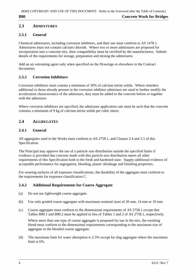
2.3 ADMIXTURES
2.3.1 General
Chemical admixtures, including corrosion inhibitors, and their use must conform to AS 1478.1. Admixtures must not contain calcium chloride. Where two or more admixtures are proposed for incorporation into a concrete mix, their compatibility must be certified by the manufacturers. Submit details of the requirements for storage, preparation and mixing the admixtures.
Add an air entraining agent only when specified on the Drawings or elsewhere in the Contract documents.
2.3.2 Corrosion Inhibitors
Corrosion inhibitors must contain a minimum of 30% of calcium nitrite solids. Where retarders additional to those already present in the corrosion inhibitor admixture are used to further modify the acceleration characteristics of the admixture, they must be added to the concrete before or together with the admixture.
Where corrosion inhibitors are specified, the admixture application rate must be such that the concrete contains a minimum of 9 kg of calcium nitrite solids per cubic metre.
2.4 AGGREGATES
2.4.1 General
All aggregates used in the Works must conform to AS 2758.1, and Clauses 2.4 and 2.5 of this Specification.
The Principal may approve the use of a particle size distribution outside the specified limits if evidence is provided that concrete made with this particle size distribution meets all other requirements of this Specification both in the fresh and hardened state. Supply additional evidence of acceptable performance for segregation, bleeding, plastic shrinkage and finishing properties.
For wearing surfaces of all exposure classifications, the durability of the aggregate must conform to the requirements for exposure classification C.
2.4.2 Additional Requirements for Coarse Aggregate
(a) Do not use lightweight coarse aggregate.
(b) Use only graded coarse aggregate with maximum nominal sizes of 20 mm, 14 mm or 10 mm.
(c) Coarse aggregate must conform to the dimensional requirements of AS 2758.1 except that Tables B80.1 and B80.2 must be applied in lieu of Tables 1 and 2 of AS 2758.1, respectively.
Where more than one type of coarse aggregate is proposed for use in the mix, the resulting blend must conform to the dimensional requirements corresponding to the maximum size of aggregate in the blended coarse aggregate.
(d) The maximum limit for water absorption is 2.5% except for slag aggregate where the maximum limit is 6%.
4 Ed 6 / Rev 7

(RMS COPYRIGHT AND USE OF THIS DOCUMENT - Refer to the Foreword after the Table of Contents)
Concrete Work for Bridges B80
(e) Use wet strength and wet/dry strength variation tests for aggregate durability assessment in accordance with AS 2758.1 with “duplicate testing” being carried out in accordance with AS 1141.22.
Durability of slag aggregate need only conform to exposure classification B1 requirements, except for wearing surfaces, which must conform to exposure classification C requirements.
2.4.3 Additional Requirements for Fine Aggregate
(a) Graded fine aggregate must conform to the dimensional requirements of AS 2758.1, but Table B80.3 applies instead of Table 3 of AS 2758.1.
Where more than one type of fine aggregate is proposed for use in the mix, the resulting blend must conform to dimensional requirements of the above paragraph.
(b) Limit water absorption to a maximum of 2.5%.
(c) Any manufactured sand used as a fine aggregate must be crushed from rock from which aggregate is produced, and conforming to Clause 2.4, and must be non-plastic when tested in accordance with AS 1289.3.
Clause 8.2.2 of AS 2758.1 does not apply to manufactured sand. The water absorption of the combined fine aggregate must not exceed 2.5%.
For manufactured sands, when tested for Methylene Blue Value (MBV) in accordance with ISSA 145, the multiple of the MBV and the passing 75 µm sieve value of any sample must not exceed 100.
For manufactured sands, the sodium sulfate loss when tested in accordance with AS 1141.24 must not exceed a weighted average loss of 6% for all exposure classifications.
Table B80.1 - Coarse Aggregate - Particle Size Distribution Requirements
Sieve aperture
Mass of sample passing (%)
Nominal size of aggregate (mm)
20 14 10
26.5 mm 100 – –
19.0 mm 85 – 100 100 –
13.2 mm – 85 – 100 100
9.5 mm 25 – 55 – 85 – 100
6.7 mm – 25 – 55 –
4.75 mm 0 – 10 – 0 – 20
2.36 mm 0 – 5 0 – 10 0 – 5
Ed 6 / Rev 7 5
(RMS COPYRIGHT AND USE OF THIS DOCUMENT - Refer to the Foreword after the Table of Contents)
B80 Concrete Work for Bridges
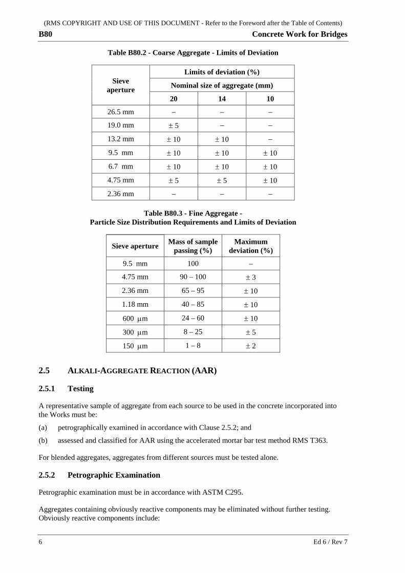
Table B80.2 - Coarse Aggregate - Limits of Deviation
Sieve aperture
Limits of deviation (%)
Nominal size of aggregate (mm)
20 14 10
26.5 mm – – –
19.0 mm ± 5 – –
13.2 mm ± 10 ± 10 –
9.5 mm ± 10 ± 10 ± 10
6.7 mm ± 10 ± 10 ± 10
4.75 mm ± 5 ± 5 ± 10
2.36 mm – – –
Table B80.3 - Fine Aggregate - Particle Size Distribution Requirements and Limits of Deviation
Sieve aperture Mass of sample passing (%)
Maximum deviation (%)
9.5 mm 100 –
4.75 mm 90 – 100 ± 3
2.36 mm 65 – 95 ± 10
1.18 mm 40 – 85 ± 10
600 µm 24 – 60 ± 10
300 µm 8 – 25 ± 5
150 µm 1 – 8 ± 2
2.5 ALKALI-AGGREGATE REACTION (AAR)
2.5.1 Testing
A representative sample of aggregate from each source to be used in the concrete incorporated into the Works must be:
(a) petrographically examined in accordance with Clause 2.5.2; and
(b) assessed and classified for AAR using the accelerated mortar bar test method RMS T363.
For blended aggregates, aggregates from different sources must be tested alone.
2.5.2 Petrographic Examination
Petrographic examination must be in accordance with ASTM C295.
Aggregates containing obviously reactive components may be eliminated without further testing. Obviously reactive components include:
6 Ed 6 / Rev 7

(RMS COPYRIGHT AND USE OF THIS DOCUMENT - Refer to the Foreword after the Table of Contents)
Concrete Work for Bridges B80
(a) opaline material;
(b) unstable silica minerals such as moderate amounts of tridymite and cristobalite; or
(c) sheared rock containing moderate amounts of strained quartz and microcrystalline quartz.
Petrographic examination must not be used alone to determine that an aggregate is non-reactive. Testing of the aggregate to Test Method RMS T363 is also required.
2.5.3 Actions Required for Control of AAR
For aggregates classified as non-reactive by Test Method RMS T363, no action for control of potential AAR is required.
Where any of the aggregates in a mix are classified as slowly reactive or reactive by Test Method RMS T363, actions required for control of potential AAR in the concrete must be in accordance with Table B80.4.
Blended cements used for control of potential AAR must be in accordance with Annexure 3211/A of Specification RMS 3211.
Aggregates classified as reactive by Test Method RMS T364 in a particular concrete mix design must not be used. Use alternative aggregates and/or alternative concrete mix designs that conform to this Specification.
Table B80.4 - Actions Required for Control of Potential AAR Based on RMS T363 Testing
Mortar bar expansion (%) in 1M NaOH (80°C) Actions Required
10 days 21 days
< 0.10 * ≥ 0.10 * Use blended cement
≥ 0.10 * >> 0.10 *
Use an alternative aggregate or Use blended cement and assess aggregate reactivity in the concrete mix using RMS T364
* Note: 0.15% for naturally occurring fine aggregates
2.6 SOLUBLE SALTS
2.6.1 Chlorides
Determine the chloride ion content by testing ground samples of hardened concrete in accordance with AS 1012.20.
Take the samples from a minimum 1.2 kg portion of the hardened concrete. Crush and grind the 1.2 kg of hardened concrete to a maximum size of 150 microns and then oven dry at 110ºC ± 5ºC for a minimum of one hour before taking the samples for analysis.
Analyse five (5) randomly selected samples of 20 ± 0.1 grams of the ground concrete for chloride ion content.
Ed 6 / Rev 7 7
(RMS COPYRIGHT AND USE OF THIS DOCUMENT - Refer to the Foreword after the Table of Contents)
B80 Concrete Work for Bridges
Use the Volhard method calibrated against a concrete with known chloride content for the tests. Modify the procedure of AS 1012.20 and use standard solutions for the analysis that bracket the expected chloride ion concentration.
Report the chloride ion content of each of the five samples and calculate and report the average chloride content and the standard deviation of the five samples.
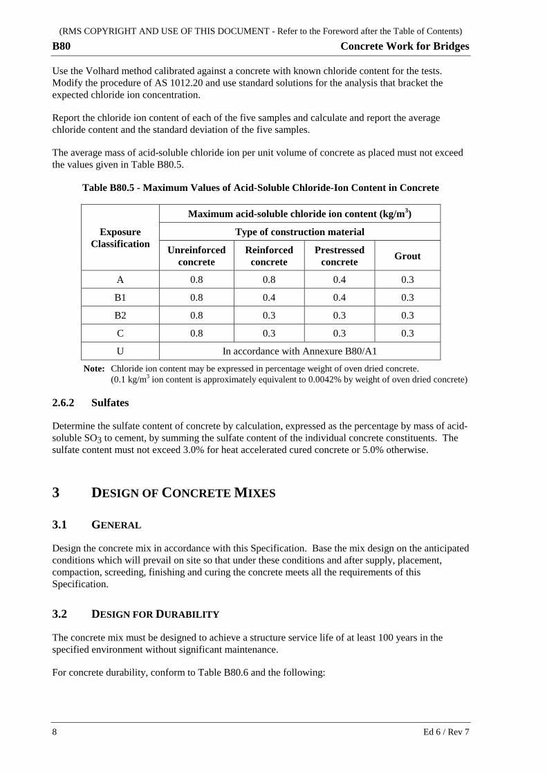
The average mass of acid-soluble chloride ion per unit volume of concrete as placed must not exceed the values given in Table B80.5.
Table B80.5 - Maximum Values of Acid-Soluble Chloride-Ion Content in Concrete
Exposure Classification
Maximum acid-soluble chloride ion content (kg/m3)
Type of construction material
Unreinforced concrete
Reinforced concrete
Prestressed concrete Grout
A 0.8 0.8 0.4 0.3
B1 0.8 0.4 0.4 0.3
B2 0.8 0.3 0.3 0.3
C 0.8 0.3 0.3 0.3
U In accordance with Annexure B80/A1
Note: Chloride ion content may be expressed in percentage weight of oven dried concrete. (0.1 kg/m3 ion content is approximately equivalent to 0.0042% by weight of oven dried concrete)
2.6.2 Sulfates
Determine the sulfate content of concrete by calculation, expressed as the percentage by mass of acid-soluble SO3 to cement, by summing the sulfate content of the individual concrete constituents. The sulfate content must not exceed 3.0% for heat accelerated cured concrete or 5.0% otherwise.
3 DESIGN OF CONCRETE MIXES
3.1 GENERAL
Design the concrete mix in accordance with this Specification. Base the mix design on the anticipated conditions which will prevail on site so that under these conditions and after supply, placement, compaction, screeding, finishing and curing the concrete meets all the requirements of this Specification.
3.2 DESIGN FOR DURABILITY
The concrete mix must be designed to achieve a structure service life of at least 100 years in the specified environment without significant maintenance.
For concrete durability, conform to Table B80.6 and the following:
8 Ed 6 / Rev 7

(RMS COPYRIGHT AND USE OF THIS DOCUMENT - Refer to the Foreword after the Table of Contents)
Concrete Work for Bridges B80
(a) For exposure classifications A and B1, concrete made with blended cement must contain a minimum of 240 kg/m3 of General Purpose or Shrinkage Limited cement conforming to Specification RMS 3211, to limit carbonation.
(b) Use blended cement containing amorphous silica only for precast concrete members. Do not use blended cement containing amorphous silica for cast-in-place concrete members, to limit cracking.
(c) Precast concrete members in exposure classification C must contain a corrosion inhibitor in accordance with Clause 2.3.2, except as provided for in Item (d) of this Clause or in Annexure B80/F, to limit chloride induced reinforcement corrosion.
(d) For precast concrete members requiring durability suitable for exposure classification C but which are not in a chloride aggressive environment, the corrosion inhibitor is not required.
(e) The water/cement ratio must not be less than 0.32 for cast-in-place concrete and 0.28 for precast concrete, to ensure cement hydration, except for cast-in-place concrete bridge decks and slabs where it must not be less than 0.40, to limit cracking.
(f) For cast-in-place concrete bridge decks and slabs the specified minimum 28 day compressive strength, fc.min(s), must not exceed 32 MPa, except for exposure classification B2 where it must not exceed 40 MPa, to limit cracking.
(g) Provide curing equivalent to a minimum of 3 days wet curing or better, to limit cracking.
(h) Self-compacting concrete may only be used for precast concrete members, except where permitted by the Principal and Clauses 3.6 and 7.8, and Annexure B80/A2.
Alternatively, submit to the Principal for consideration a Concrete Durability Plan specific to the Works that will achieve the intent of this Clause and that will prevent the adverse effects specified in Clause 3.3. Demonstrate in the Concrete Durability Plan a durability performance equivalent to or better than that achieved by conforming to Table B80.6 and the preceding items of this Clause.
The Concrete Durability Plan must:
(i) fully detail and quantify the effect of each factor affecting concrete durability on the Works, using field test results and supporting durability calculations;
(ii) propose the measures to be taken during the Works to achieve the specified structure service life; and
(iii) propose suitable concrete mixes for each structure and/or individual members on the Works together with laboratory test results demonstrating conformity with the Concrete Durability Plan.
Ed 6 / Rev 7 9

(RMS COPYRIGHT AND USE OF THIS DOCUMENT - Refer to the Foreword after the Table of Contents)
Concrete Work for Bridges B80
Table B80.6 - Durability Requirements for Concrete
Exposure classification
Minimum cement content
Maximum cement content
Maximum water/ cement
Minimum water/ cement
Maximum chloride test coefficients at 20°C
(x 10-12 m2/sec)
Minimum strength for durability Actions required
(kg/m3) (kg/m3) ratio (by mass)
ratio (by mass)
NT Build 443 (De)
NT Build 492 (DRMC)
fc.min(d) (MPa)
Cast-in-place Concrete
A 320 400 0.56 0.4 N/A N/A 25 N/A
B1 320 450 0.50 0.4 N/A N/A 32 N/A
B2 370 500 0.46 0.32 3.5 8.0 40 Use blended cement with minimum 25% FA or 50% BFS
C 420 550 0.40 0.32 2.0 4.0 50 Use blended cement with minimum 65% BFS
U In accordance with Annexure B80/A1
Precast Concrete
A, B1 320 600 0.5 0.28 N/A N/A 40 N/A
B2 370 600 0.46 0.28 3.5 8.0 60 Use blended cement
C 420 600 0.40 0.28 2.0 4.0 60 Use blended cement
Notes: 1. N/A denotes not applicable for this exposure classification. FA denotes fly ash and BFS denotes ground granulated iron blast furnace slag conforming to Specification RMS 3211. 2. De denotes effective diffusion coefficient from Nordtest NT Build 443. 3. DRMC denotes rapid migration coefficient from Nordtest NT Build 492. 4. Continuously standard moist-cure after demoulding specimens for the Nordtest NT Build 443 and NT Build 492 tests and test at an age of 56 and 28 days respectively. 5. The specified coefficients are based on the minimum concrete covers specified in AS 5100.5:2004 Table 4.10.3 (A). If the specified corrosion inhibitor is included, the minimum cover
may be reduced by 10 mm. 6. The Principal may modify the specified coefficients if the concrete cover is increased. 7. The specified coefficients are for a test temperature of 20oC. Modify the required coefficients for a given temperature as follows:
(De or DRMC)req = 4.15 e – 0.0703 T1 where T1 is the specified temperature.
Ed 6 / Rev 7 10

(RMS COPYRIGHT AND USE OF THIS DOCUMENT - Refer to the Foreword after the Table of Contents)
Concrete Work for Bridges B80
3.3 PREVENTION OF ADVERSE EFFECTS
Design the concrete mix for prevention of adverse effects arising from excessive drying shrinkage, alkali-aggregate reactions, soluble salts, inadequate compaction and cracking, and from exposure to acid sulfate soils, chloride ingress and carbonation.
3.3.1 Drying Shrinkage
Maximum drying shrinkage must be in accordance with Clause 3.7.
3.3.2 Alkali-Aggregate Reactions (AAR)
Control alkali-aggregate reactions in accordance with Clause 2.5.
3.3.3 Soluble Salts
Maximum soluble salts must be in accordance with Clause 2.6.
3.3.4 Compaction
Concrete compaction must be in accordance with Clauses 7.4.3 and 8.3.
3.3.5 Cracking
Maximum crack widths must be in accordance with Clause 7.2.
3.3.5.1 Plastic Shrinkage Cracking
Control plastic shrinkage cracking in accordance with Clause 7.6.
3.3.5.2 Thermal Cracking
Control thermal cracking by using blended cement containing fly ash or blast furnace slag, or by chilling the mix water or by insulating the concrete member. Thermal cracking is usually aggravated with large volume concrete members.
Model the effects in larger members of temperature increases as a result of cement hydration during production and curing of the concrete member and use measures to prevent thermal cracking.
Limit the temperature of all concrete members following concrete placement to a maximum of 70°C.
3.3.6 Acid Sulfate Soils (ASS)
For concrete structures located in exposure classification U due to the presence of acid sulfate soils, design the concrete mix in accordance with Annexure B80/A1.
3.3.7 Chloride Ingress
For the exposure classifications specified on the Drawings, design the concrete mix against chloride ingress in accordance with Table B80.6. The values of diffusion or migration coefficients for the concrete mix must be verified on a trial mix with samples taken for testing for chloride resistance.
Ed 6 / Rev 7 11

(RMS COPYRIGHT AND USE OF THIS DOCUMENT - Refer to the Foreword after the Table of Contents)
B80 Concrete Work for Bridges
Carry out chloride resistance testing in accordance with Nordtest NT Build 443 at a concrete age of 56 days or Nordtest NT Build 492 at a concrete age of 28 days. The Principal will specify which test method to use, depending on the time available to obtain the test results.
3.3.8 Carbonation of Concrete
Refer to Item (a) of Clause 3.2.
3.4 CURING
The curing of the concrete must conform to either Provision A - (Performance) or Provision B - (Method), as specified in Clauses 3.4.1 and 3.4.2.
3.4.1 Curing Provision A - (Performance)
For the exposure classifications specified on the Drawings, the effectiveness of the curing of the concrete used in the Works must be in accordance with Table B80.7.
Test the effectiveness of the curing in accordance with Test Method RMS T362. Carry out sorptivity testing by other than a NATA registered laboratory for this test, if approved by the Principal.
The maximum sorptivity penetration depth must be verified on a trial mix using the method and duration of curing (“curing regime”) proposed for use on the Works.
At the trial mix stage, the curing of the sorptivity test specimen must be identical to that proposed for the concrete member. At the construction stage, the curing of the concrete member must be identical to that of the sorptivity test specimen. Provide charts of the curing temperature and humidity versus time to verify that the required curing has been achieved.
Table B80.7 - Curing Requirements for Concrete (Provision A)
Exposure classification
Maximum sorptivity penetration depth (mm)
General Purpose cement
Blended cement
A 35 35
B1 25 25
B2 N/A 20
C N/A 8
U In accordance with Annexure B80/A1
3.4.2 Curing Provision B - (Method)
For the exposure classifications specified on the Drawings, the curing of the concrete member must be in accordance with Annexure B80/E using one of the methods of curing specified in Clause 7.12.
12 Ed 6 / Rev 7

(RMS COPYRIGHT AND USE OF THIS DOCUMENT - Refer to the Foreword after the Table of Contents)
Concrete Work for Bridges B80
3.5 TARGET STRENGTH FOR MIX DESIGN
Design the concrete mix to achieve a target strength fc.md such that:
fc.md ≥ fc.min + Mcontrol and
fc.max ≤ fc.min + 2.0 Mcontrol
where:
(a) fc.min is the greater of fc.min(s) and fc.min(d);
(b) fc.min(s) is the specified minimum 28 day compressive strength as stated on the Drawings, or elsewhere in the Specification;
(c) fc.min(d) is the minimum 28 day compressive strength required for durability obtained from Table B80.6;
(d) Mcontrol is the margin nominated for variations in strength as defined in Clause 4.1; and
(e) fc.max is the maximum 28 day compressive strength test result permitted for the trial mix, unless otherwise approved by the Principal.
Unless specified otherwise on the Drawings or approved by the Principal:
(i) the target strength fc.md for cast-in-place deck concrete must not exceed 42 MPa except for exposure classification B2 where it must not exceed 50 MPa;
(ii) the target strength fc.md for all other concrete must not exceed 75 MPa; and
(iii) Mcontrol must not exceed 10 MPa.
3.6 LIMITATIONS ON SLUMP
Unless specified otherwise on the Drawings, or approved by the Principal, the concrete slump of the nominated mix (nominated slump) must not exceed 180 mm. Where a nominated slump in excess of 180 mm is proposed, demonstrate by way of a Test Member in accordance with Clause 5.3.2, that the concrete may be placed, compacted and finished without deleterious effects.
Unless approved otherwise by the Principal, the above limitations on slump may be waived only for the bridge members specified in Annexure B80/A2 for which self-compacting concrete may be used in accordance with Annexure B80/G.
3.7 LIMITATIONS ON SHRINKAGE
Prepare concrete specimens from the nominated mix in accordance with AS 1012.13 for the purpose of shrinkage testing. Measure the shrinkage of the specimens in accordance with AS 1012.13.
Shrinkage of the concrete specimen after either of the 3 or 8 weeks’ drying periods must conform to Table B80.8.
Ed 6 / Rev 7 13

(RMS COPYRIGHT AND USE OF THIS DOCUMENT - Refer to the Foreword after the Table of Contents)
B80 Concrete Work for Bridges
Table B80.8 - Maximum Shrinkage Strain of Concrete Specimens
Exposure classification
Maximum shrinkage strain (microstrain)
Drying period
3 Weeks 8 Weeks
A 570 690
B1, B2 500 (600#) (650§) 630 (720#) (760§)
C 430 (530#) (550§) (650*) 560 (650#) (670§) (760*)
U In accordance with Annexure B80/A1
Notes: # For self-compacting concrete. § For concretes with slag-blended cement. * For precast members where the specified corrosion inhibitor has been included in the mix.
3.8 NOMINATED MIXES
3.8.1 Submission of Nominated Mixes
Submit to the Principal the details of each concrete mix and the proposed curing regime together with a certificate stating that the nominated mix, its constituents and the proposed curing regime, conform to this Specification.
Alternatively, propose a mix which conforms to this Specification, is currently approved and is listed on the Register of RMS Approved Concrete Mixes available at: (http://www.rms.nsw.gov.au/business-industry/partners-suppliers/register-of-materials/concrete-mix/conform-conc-mix.pdf).
HOLD POINT
Process Held: Use of each nominated mix.
Submission Details: (a) (i) all details in Clause 3.8.2; or (ii) nomination of a mix from the Register of RMS Approved Concrete Mixes; and (b) a statement stating that the mix conforms to this Specification and is suitable for its intended use, at least 5 working days before the concrete mix is proposed to be used.
Release of Hold Point: The Principal will consider the submitted documents, and may carry out surveillance and audit, prior to authorising the release of the Hold Point.
Prepare trial mixes in accordance with AS 1012.2 using the proposed materials and mix proportions, including all admixtures.
Batch a trial mix at the highest water/cement ratio conforming to the allowable slump and water content tolerances specified in AS 1379 for the nominated mix. For mixes with a nominated water/cement ratio less than 0.40, batch an additional trial mix at the lowest water/cement ratio
14 Ed 6 / Rev 7

(RMS COPYRIGHT AND USE OF THIS DOCUMENT - Refer to the Foreword after the Table of Contents)
Concrete Work for Bridges B80
conforming to the allowable slump and water content tolerances. Allow for batching tolerances and anticipated variations in aggregate moisture content.
Report the test results for the hardened concrete prepared from the trial mixes.
From the trial mix results, nominate the water/cement ratio and slump for production. Include the nominated values on the delivery dockets. AS 1379 Clause 4.2 provides for tolerances on production batch ingredients.
Where an RMS approved concrete mix is nominated for use in the Works, submit identification details of the mix and the concrete mix design to the Principal.
3.8.2 New Concrete Mix Design
The submission for a mix not currently approved must include the following details:
(a) Material Constituents
For each constituent and any individual components making up the constituent:
(i) Source; and
(ii) Current test results not more than 12 months old for the characteristics and properties specified in Clause 2.
(b) Mix Design
(i) Constituent quantities;
(ii) Method of controlling alkali-aggregate reactions as specified in Clause 2.5;
(iii) Trial mix water/cement ratio and corresponding nominated water/cement ratio;
(iv) Condition of constituents used in the mix design e.g. moisture condition of aggregates;
(v) fc.md, fc.min, fc.min(s), fc.max and fc.min(d) determined in accordance with Clause 3.5;
(vi) Applicable exposure classification(s);
(vii) Trial mix slump and corresponding nominated slump;
(viii) For concrete containing high range water reducers: final slump and reversion time; and
(ix) Nominated coarse and fine aggregate particle size distributions.
(c) Batching, Mixing and Transport
(i) Methods;
(ii) Level of control and accuracy of batching;
(iii) Level of control and accuracy of determination of the aggregate moisture content;
(iv) Mcontrol and method of determination of Mcontrol; and
(v) Minimum mixing time.
(d) Curing Regime
(i) Method and duration of curing;
(ii) Anticipated minimum and maximum ambient temperatures and relative humidity during the curing period; and
Ed 6 / Rev 7 15

(RMS COPYRIGHT AND USE OF THIS DOCUMENT - Refer to the Foreword after the Table of Contents)
B80 Concrete Work for Bridges
(iii) For curing Provision A only: maximum sorptivity penetration depth together with the applicable curing regime accompanied by temperature and relative humidity versus time graphs.
(e) Other Test Results for Hardened Concrete Characteristics
(i) 28 day compressive strength in accordance with AS 1012.9 (cylinders must be moulded in accordance with AS 1012.8.1 using rodding only);
(ii) Shrinkage in accordance with AS 1012.13;
(iii) Sulfate and chloride ion contents in accordance with Clause 2.6;
(iv) Chloride resistance in accordance with Clause 3.3.7; and
(v) Trial mix report in accordance with AS 1012.2.
3.9 VARIATIONS TO NOMINATED MIXES
The quantities of the constituents in a nominated mix may be varied to improve the quality of the concrete. Variations to the quantities of constituents in the nominated mix must not exceed the following:
(a) Cement: 3% by mass of each constituent.
(b) Aggregates: 5% by mass of each constituent.
(c) Water: 3% by volume and/or mass.
(d) Admixture: 20% by volume and/or mass of each admixture and within the manufacturer's recommendations.
Notify the Principal in writing and submit written details of such variations to a nominated mix before commencing production with the varied quantities.
Notwithstanding the above provisions, the varied concrete mix must:
(i) not have a water/cement ratio exceeding that nominated for the concrete mix (refer to Clause 3.8);
(ii) conform to Clause 3.2 for minimum cement content and maximum water/cement ratio; and
(iii) conform to Specification RMS 3211 for the range of SCMs in blended cement.
If you wish to vary the quantities of the constituents in excess of the above amounts, or wish to change the type or source of supply of any constituent, or vary the curing regime, submit a new nominated mix for approval in accordance with Clause 3.8, unless approved otherwise by the Principal.
4 SUPPLY AND DELIVERY OF CONCRETE
4.1 GENERAL
All concrete supplied for use in the Works must conform to the approved nominated concrete mixes.
Produce and deliver concrete to the site of the Works or to the precasting yard in accordance with AS 1379 and this Specification.
16 Ed 6 / Rev 7

(RMS COPYRIGHT AND USE OF THIS DOCUMENT - Refer to the Foreword after the Table of Contents)
Concrete Work for Bridges B80
Classify all concrete for use in the Works as Special Class designated “S” in accordance with Clause 1.5.4 of AS 1379. Nominate the method of production assessment relevant to the plant in accordance with AS 1379.
Nominate a margin for strength which is consistent with the nominated method of production assessment under which the plant operates. This margin for strength, Mcontrol, is the measure of the level of control for the nominated plant producing the nominated mix.
Dispose of water, contaminants, debris, excess concrete and other materials from concrete supply operations in accordance with Specification RMS G36.
4.2 MOISTURE CONTENT OF AGGREGATES
Store the fine and coarse aggregates in the saturated surface dry condition or wetter prior to and during batching.
Determine the moisture content of the fine and coarse aggregates prior to concrete production for the day, and whenever conditions change, either by a moisture meter or by other equivalent devices or methods. Make corrections to the mass of all aggregates and the volume of water used in the mix commensurate with the moisture content determined so that the nominated water/cement ratio is achieved for all batches supplied for the Works.
4.3 ADDITIONAL REQUIREMENTS FOR MIXING
4.3.1 Equipment
Do not use continuous mixers.
4.3.2 Discharging of Mixer
Discharge the entire contents of the mixer before charging it with a new batch.
4.3.3 Maximum Mixing Time
Where by reason of delay it is necessary to hold a batch in the mixer, mixing may be continued for a maximum of ten minutes, except for split drum mixers where the maximum time that mixing may be continued is five minutes.
For longer delays, the batch may be held in the mixer and turned over at regular intervals, subject to the time limits specified for incorporation of the concrete into the work not being exceeded.
4.3.4 Delivery
Transport concrete produced at a remote central batching plant to the point of discharge by truck-mounted drum mixers conforming to AS 1379 and this Specification. On completion of batching, continuously agitate the concrete until it is thoroughly mixed. On completion of mixing, continuously agitate the concrete until it is fully discharged. The agitation speed and duration to achieve thorough mixing must be as specified by the manufacturer of the equipment.
Before discharging from a truck-mounted drum mixer, agitate the concrete on-site for a minimum of three minutes at the mixer’s rated mixing speed.
Ed 6 / Rev 7 17

(RMS COPYRIGHT AND USE OF THIS DOCUMENT - Refer to the Foreword after the Table of Contents)
B80 Concrete Work for Bridges
All concrete batches must be delivered with a delivery docket / identification certificate containing the following details:
(a) Delivery docket number;
(b) Truck number;
(c) Batch number;
(d) Date and time batched;
(e) Batch quantity;
(f) Project name;
(g) Mix type and identification;
(h) Strength grade;
(i) Nominated slump;
(j) Nominated water/cement ratio;
(k) Volume of free water in the batch;
(l) Volume of all water added after batching;
(m) Total free water in the batch;
(n) Mass of cement in the batch;
(o) Actual water/cement ratio at discharge;
(p) Time at discharge;
(q) Total quantity of the deliveries for the pour; and
(r) Concrete supplier and plant details.
4.3.5 Period for Completion of Discharge, Placement and Compaction
Unless a hydration control admixture is added to the approved mix to delay hydration, place and compact the concrete within 1.5 hours from the addition of the cement to the aggregates.
Where a hydration control admixture is added to the approved mix to delay hydration and extend the setting time beyond 1.5 hours, nominate the extended setting time and conform to the following:
(a) Provide NATA endorsed test reports in accordance with Clause 2.3.1 proving conformity of the admixture to AS 1478.1.
(b) Soluble salt content must conform to Clause 2.6.
(c) Carry out trials with the mix containing the admixture prior to and under the most adverse conditions that would most likely occur at the site over the range of days of the pours to demonstrate that there will be no adverse effects on the plastic and hardened concrete including shrinkage tests in accordance with Clause 3.7 and additional compression strength cylinders in accordance with Clause 8.2 taken after the addition of the second part of the admixture.
(d) Thoroughly remix the concrete after addition of the second part of the admixture but before discharge for a minimum of three minutes at the mixer’s rated speed.
18 Ed 6 / Rev 7

(RMS COPYRIGHT AND USE OF THIS DOCUMENT - Refer to the Foreword after the Table of Contents)
Concrete Work for Bridges B80
4.4 SLUMP AND WATER/CEMENT RATIO TOLERANCES
Check and record the slump of the concrete within 45 minutes of adding cement to the aggregate or at discharge. Also check and record the slump immediately prior to discharge when the actual haul time exceeds 45 minutes and/or when water is added to a mixed batch in accordance with Clause 4.5.
Check the slump of the concrete in accordance with AS 1379 except for the frequency of sampling which must be in accordance with Annexure B80/L.
If the measured slump is not within the specified limits, carry out one repeat test immediately from another portion of the same sample. If the value obtained from the repeat test falls within the specified limits, the concrete represented by the sample is deemed to conform; otherwise reject it.
Do not incorporate concrete into the Works if its slump or water/cement ratio is outside the specified tolerances of AS 1379.
For batches produced with a high level of process control, the Principal may accept proposals, in accordance with RMS Q, for a reduced frequency of slump checking compared to Annexure B80/L.
The water/cement ratio of each batch must conform to Item (b) of Clause 4.2.1.2 of AS 1379.
4.5 ADDITION OF WATER TO A MIXED BATCH
Provided a hydration control admixture has not been added to the approved mix to delay hydration, water may be added to a mixed batch of concrete prior to the commencement of discharge providing the following conditions are satisfied:
(a) Less than 45 minutes have elapsed since cement was added to the aggregate;
(b) Immediately after the addition of any water, operate the mixing mechanism at mixing speed for at least 3 minutes, and for such additional time as may be necessary to re-establish uniformity of the mix;
(c) The total quantity of water added is not more than 9 kg/m3, and the nominated water/cement ratio plus 10% tolerance and maximum water/cement ratio in Table B80.6 are not exceeded;
(d) The quantity of water added is measured and recorded;
(e) The slump of the concrete is checked after the water has been added, in accordance with Clause 4.4.
Once discharge of a batch has commenced, do not add further water to that batch.
4.6 TEMPERATURE AT POINT OF DELIVERY
Do not use concrete if its temperature at the point of discharge is less than 10°C or more than 32°C except for precast concrete members and cast-in-place piles where the minimum and maximum concrete temperatures must be 5°C and 35°C respectively.
4.7 PRESENCE OF CORROSION INHIBITOR IN FRESH CONCRETE
Where the corrosion inhibitor is specified in the nominated mix, determine the presence and quantity of the calcium nitrite within the fresh concrete in accordance with Test Method RMS T371. The frequency of sampling must be in accordance with Annexure B80/L.
Ed 6 / Rev 7 19
(RMS COPYRIGHT AND USE OF THIS DOCUMENT - Refer to the Foreword after the Table of Contents)
B80 Concrete Work for Bridges
5 FORMWORK
5.1 GENERAL
Formwork, including all temporary supporting members, must conform to AS 3610 and this Specification.
With the exception of Clauses 5.1, 5.3, 5.8, 5.9 and 5.10, Clause 5 does not apply to formwork for precast concrete members cast in off-site precasting yards.
Design the formwork to account for all load cases in accordance with AS 3610. The design and details must also account for stream flow, traffic impact, flooding, ground conditions, effect of post-tensioning and any other applicable conditions. Where formwork is intended for re-use, allow in the design for the deterioration of the materials following their use and handling.
Supplement the foundation investigation for the bridge design with additional foundation information, if necessary, to complete the formwork design.
5.2 FORMWORK DESIGN, DOCUMENTATION AND CERTIFICATION
5.2.1 Quality Management System Requirements
Attention is drawn to RMS Q for the design control of temporary structures. These requirements apply to the design of formwork.
5.2.2 Project Documentation
Project documentation must conform to Section 2 of AS 3610.
5.2.3 Formwork Design and Documentation
Note clearly on the formwork drawings all relevant formwork construction requirements including design assumptions, foundation preparation, footing details and precamber diagrams. The formwork drawings must be sufficiently comprehensive and clearly presented so that erection and inspection are carried out without reference to any other documentation.
Design any steel girders used for support and all associated bolted or welded splices in accordance with AS 5100. All welded splices must be full penetration butt welds conforming to Specification RMS B201. All bolts and other fasteners must conform to RMS B201.
5.2.4 Submission of Formwork Documentation and Certification
For the purposes of this clause, the formwork for the various members of the bridge structure is divided into three Risk Categories as detailed in Table B80.9.
20 Ed 6 / Rev 7

(RMS COPYRIGHT AND USE OF THIS DOCUMENT - Refer to the Foreword after the Table of Contents)
Concrete Work for Bridges B80
Table B80.9 - Risk Categories for Formwork
Category Bridge Members
A Low Risk
(a) Abutments, pilecaps, footings, piers, columns and walls, with heights less than 3 metres
(b) Members not included in either Category B or Category C
B Moderate
Risk
(a) Abutments, pilecaps, footings, piers, columns and walls, with heights greater than 3 metres and less than 6 metres
(b) Headstocks more than 3 metres off the ground
(c) Decks and off-ground slabs with maximum thickness less than 600 mm
C High Risk
(a) Abutments, pilecaps, footings, piers, columns and walls, with heights greater than 6 metres
(b) Parapets
(c) Decks and off-ground slabs with maximum thickness greater than 600 mm
(d) Concrete box girders
(e) Any member for which self-compacting concrete is proposed
(f) Job specific bridge members listed in Annexure B80/A3
The submission of formwork documentation and certification for each Category must be in accordance with Table B80.10.
For bridges over or adjacent to railways and/or roads conveying more than 5000 vehicles/day in any lane, formwork for the members listed under Category B must conform to the submission requirements of Category C of Table B80.10.
The submission for the use of a formwork assembly more than once for members listed under Category C need only conform to the requirements of Category A of Table B80.10 after its initial use, if approved by the Principal.
Table B80.10 - Submission Requirements for Formwork
Category
Formwork documentation Design certification Erected formwork
certification
Time of submission by Time of
submission by Time of submission
A Low Risk N/A N/A N/A Contractor
In accordance with
Clause 7.3 (HP)
B Moderate
Risk
Prior to placing reinforcement Engineer
Prior to placing reinforcement
(HP) Contractor
C High Risk
Prior to erecting formwork Engineer
Prior to erecting formwork
(HP)
Contractor for parapets, Engineer
for all other members
Notes: (HP): Hold Point N/A: Not Applicable
Ed 6 / Rev 7 21

(RMS COPYRIGHT AND USE OF THIS DOCUMENT - Refer to the Foreword after the Table of Contents)
B80 Concrete Work for Bridges
When certification by an Engineer is required by Table B80.10, nominate an Engineer who is a member of Engineers Australia (or equivalent) and who is experienced in the design and erection of formwork of at least similar complexity.
When design certification of formwork is required in Table B80.10, the certification must state that the design of the formwork and the formwork documentation conform to AS 3610 and this Specification. Where multiple systems are combined to create the formwork, the design certification must cover the full extent of formwork used, including any interfaces and any required bracing and stiffeners.
The certification for erected formwork must state that the formwork has been erected in accordance with either the formwork documentation for Category A, or the certified design for Categories B and C, as applicable.
Any changes proposed to the certified design or erected formwork must be accompanied by documentation and certification conforming to this Clause.
HOLD POINT (Does not apply to Category A formwork)
Process Held: For Category B formwork – Placement of reinforcement. For Category C formwork – Erection of formwork.
Submission Details: For Categories B and C, formwork documentation and Engineer's design certification in accordance with Clause 5.2.
Release of Hold Point: The Principal will consider the submitted documents prior to authorising the release of the Hold Point. Where the Principal has concerns about the adequacy of the formwork documentation or certification, the Principal may order an independent verification of the formwork design at your expense before releasing the Hold Point.
5.3 SURFACE FINISH
5.3.1 Class of Finish
For the purpose of this Specification, the classes of surface finish are as defined in AS 3610.
Design and construct the formwork to produce concrete with the following Class of finish unless otherwise stated in Annexure B80/A4 or the Drawings:
(a) Structures beyond 1 km from coast:
(i) precast girders and piles - Class 2 in accordance with Clause 3.4.5 of AS 3610. The dimensional tolerances of Specifications RMS B110 and RMS B115 take precedence over this Specification;
(ii) deck soffit between precast girders - Class 2X;
(iii) all piers, abutment and retaining wall surfaces exposed to view - Class 2X;
(iv) all other external surfaces including soffits of precast planks - Class 2; and
(v) all internal and permanently hidden surfaces - Class 3.
22 Ed 6 / Rev 7

(RMS COPYRIGHT AND USE OF THIS DOCUMENT - Refer to the Foreword after the Table of Contents)
Concrete Work for Bridges B80
(b) Structures within 1 km from coast:
(i) as for (a) except that Class 2X becomes Class 2.
The surface finish for Class 2X is the surface finish which conforms to Class 2 except that the blowholes requirement is relaxed to Class 3 (refer Figure B3 of AS 3610).
5.3.2 Test Members
Test members are not required unless specified in Clause 3.6 or Annexure B80/A4 or the Drawings.
When test members are required they must be designed and constructed in accordance with AS 3610. The method of constructing the test members must effectively simulate the formwork, reinforcement layout and concreting operations to be applied in the Works.
HOLD POINT (If test members are required)
Process Held: Erection or prefabrication of formwork for members specified in Annexure B80/A4 or on the Drawings.
Submission Details: Give the Principal two working days notice in writing of the proposed placement of concrete in the test member to permit observation of the process. Thereafter, give the Principal the opportunity to inspect the completed member.
Release of Hold Point: The Principal will consider the method of construction and the finished test member, prior to authorising the release of the Hold Point.
5.4 SITE-RELATED REQUIREMENTS
Formwork for concrete intended for composite action with a member previously constructed must be designed to be supported only from that member and in such a manner that placing of concrete in the formwork, or any other construction loads, does not produce separation or differential movement between the member and the formwork.
Formwork for cross girders may be supported off the substructure.
5.5 CONSTRUCTION JOINTS
Construct the Works with construction joints at the locations shown on the Drawings. If additional construction joints or the relocation of those shown on the Drawings is required, submit details of the proposals with the formwork documentation. Make any additional construction joints perpendicular to the longitudinal axis of a member.
Unless shown otherwise on the Drawings, do not locate construction joints in salt or brackish water from 1.0 m below minimum low water to 1.0 m above maximum high water tide levels.
Locate construction joints at the base of columns or walls at least 100 mm above the tops of the footings or pilecaps.
Form construction joints on visible faces by using suitably dressed timber beading, or by other means, so that the joints are straight and regular.
Ed 6 / Rev 7 23
(RMS COPYRIGHT AND USE OF THIS DOCUMENT - Refer to the Foreword after the Table of Contents)
B80 Concrete Work for Bridges
At horizontal joints where the formwork for the pour above the joint is anchored to the concrete below the joint, pre-tighten the form anchor bolts against the face of the supporting concrete. The pre-tightening must prevent the formwork from separating from the supporting face under the pressure of fresh concrete to form gaps.
At vertical joints in cast-in-place superstructures, place continuous supports directly under the formwork at the joint location. The method of providing and fixing these supports must prevent the formwork from separating from the hardened concrete of the previous pour when the fresh concrete is placed against it.
5.6 MATERIALS FOR FORMWORK SURFACES
The formwork for exposed concrete surfaces must be steel plate conforming to AS/NZS 1594 or plywood conforming to AS/NZS 2271. Make plywood from panels having uniform widths of not less than 1 m and uniform lengths of not less than 2 m, except where the dimensions of the member formed are less than these minimum panel dimensions. Place plywood panels with the grain of the outer plies perpendicular to the studding or joists.
Place all form panels in a neat and symmetrical pattern.
Where shown on the Drawings, use dressed timber for exposed concrete surfaces instead of plywood or steel.
Where left in place, do not use expanded metal mesh as formwork, including for the forming of construction joints.
Sealed penetrations through the formwork may be permitted for dowel bars, tie rods and the like.
Forms for surfaces which will be completely enclosed or permanently hidden below the ground may be constructed from dressed or rough sawn timber, steel, fibre reinforced cement sheets or plywood. Do not use particleboard, chip board or masonite.
Where indicated on the Drawings, narrow spaces between concrete faces may be formed by the use of suitable rigid foamed plastic material (polystyrene or similar). Unless otherwise noted on the Drawings, this material may be left in the finished concrete. The foamed plastic material must have sufficient rigidity to prevent appreciable deformation during concreting, but must not present significant resistance to the expected relative movement of the adjacent concrete faces in the finished structure.
The foamed plastic material may be attached to either the forms or the previously cast concrete surfaces, but any adhesive used must be of a type which will not dissolve or otherwise damage the plastic material. Take care to prevent the foamed plastic being damaged by fire, petroleum products, or any other solvents, before the concrete has hardened.
5.7 ERECTION OF FORMWORK
5.7.1 General
Erect the formwork strictly in accordance with the certified formwork documentation and Drawings.
Treat the interior surface of the formwork and any removable items so that adhesion of the concrete does not occur. Commercial quality form release agents, oil or grease are acceptable, provided that
24 Ed 6 / Rev 7
(RMS COPYRIGHT AND USE OF THIS DOCUMENT - Refer to the Foreword after the Table of Contents)
Concrete Work for Bridges B80
the treatment on formwork against surfaces to be exposed is of a type that will not stain or discolour the concrete surface.
Apply the treatment in accordance with the manufacturer’s instructions. Spread the treatment uniformly in a thin film and remove any surplus prior to placing the concrete. In the case of unlined timber forms, thoroughly wet the timber before treating.
Reinforcement, tendons, and embedments must not be soiled by the treatment used. If any reinforcement is soiled, clean it thoroughly. Do not use treatments where concrete surfaces are to receive an applied finish, unless otherwise approved by the Principal. Use only treatments compatible with any applied curing compound so that its adhesion to the concrete is not affected.
Before commencing placement of concrete, remove all loose tie wire, dirt, wood chips, hardened concrete or mortar, and all other foreign matter from the forms.
Make joints in formwork mortar-tight to prevent slurry loss and subsequent honeycombing.
5.7.2 Surveying Control
Control all survey activities in accordance with Specification RMS G71.
Fabricate and erect the formwork to achieve the specified dimensions, levels and alignment of the completed Works within the specified tolerances. Make allowance for the deflections of the formwork which may occur before and during concreting.
Carry out all necessary investigations and calculations to ensure that the estimated deflections are reliable for the erected formwork and actual site conditions.
Maintain records for the checking and verification of the following items at each listed location:
As planned
(a) the designed characteristic (level, dimension etc) at that point on the structure as shown on the Drawings;
(b) the calculated or estimated deflection/settlement of the formwork prior to and during concreting;
(c) the target characteristic for the formwork (allowing for deflection/settlement); and
(d) the specified tolerance on final location of the structure at that point.
As measured
(e) the characteristic as set out;
(f) the characteristic as verified;
(g) the difference between the verified value and the target value; and
(h) the magnitude of any out of tolerance measurement (i.e. the amount by which the measured difference exceeds the specified tolerances).
5.8 TOLERANCES
Design, document and erect the formwork so that, after it is removed, the formed and unformed surfaces have the dimensions shown on the Drawings within the tolerances given in Table B80.11 and conform to the surface finish requirements of Clause 5.3.
Ed 6 / Rev 7 25

(RMS COPYRIGHT AND USE OF THIS DOCUMENT - Refer to the Foreword after the Table of Contents)
B80 Concrete Work for Bridges
Achieve the tolerances in Table B80.11 at the completion of the Works for cast-in-place and precast concrete members.
Locate all fitments and embedments with sufficient accuracy to prevent any misfit or misalignment between mating components.
Table B80.11 - Dimensional Tolerances for Formed and Unformed Surfaces
Item
Tolerance (mm) unless shown
otherwise
(i) Footings:
Plan dimensions for formed footings and pilecaps –10, +50
Plan dimensions for unformed footings –0, +150
Thickness < 300 mm –5, +25
Thickness ≥ 300 mm –10, +50
Top of footing or pilecap reduced level –25, +25
Departure from the plan position in any direction 50
(ii) Variation in cross section of columns, piers, headstocks, slabs, walls, beams and similar parts (excluding deck slabs and barrier end posts):
< 3 m –5, +15
≥ 3 m –10, +25
(iii) Variation of cross section of barrier end posts: –5, +5
(iv) Decks:
Variation in thickness of deck slabs (after allowing for corrections for camber or hog and variations in design loads, forces and load effects). –5, +15
Deviation of top of deck slab reduced level/s from design after allowing for corrections for camber or hog and variations in design loads, forces and load effects. –10, +5
Flatness of top surface of bridge deck in any direction (after allowing for superelevation and vertical curvature or grade)
3 mm in 3 m (1/1000)
(v) Deck joints:
Width of slot –3, +3
(vi) Variation from vertical of specified batter of columns, piers, walls, kerbs and barriers:
Unexposed concrete 12 mm in 3 m (1/250)
Exposed concrete 6 mm in 3 m (1/500)
26 Ed 6 / Rev 7
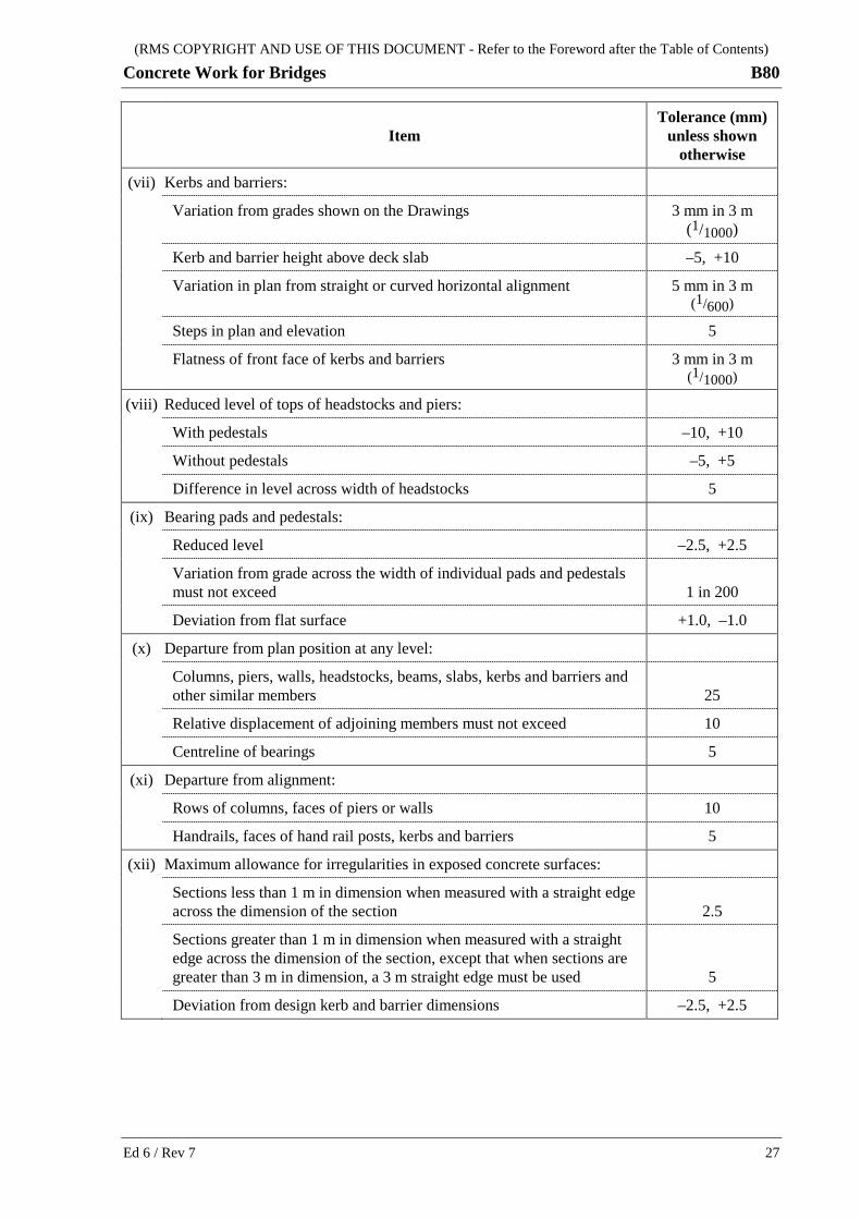
(RMS COPYRIGHT AND USE OF THIS DOCUMENT - Refer to the Foreword after the Table of Contents)
Concrete Work for Bridges B80
Item
Tolerance (mm) unless shown
otherwise
(vii) Kerbs and barriers:
Variation from grades shown on the Drawings 3 mm in 3 m (1/1000)
Kerb and barrier height above deck slab –5, +10
Variation in plan from straight or curved horizontal alignment 5 mm in 3 m (1/600)
Steps in plan and elevation 5
Flatness of front face of kerbs and barriers 3 mm in 3 m (1/1000)
(viii) Reduced level of tops of headstocks and piers:
With pedestals –10, +10
Without pedestals –5, +5
Difference in level across width of headstocks 5
(ix) Bearing pads and pedestals:
Reduced level –2.5, +2.5
Variation from grade across the width of individual pads and pedestals must not exceed 1 in 200
Deviation from flat surface +1.0, –1.0
(x) Departure from plan position at any level:
Columns, piers, walls, headstocks, beams, slabs, kerbs and barriers and other similar members 25
Relative displacement of adjoining members must not exceed 10
Centreline of bearings 5
(xi) Departure from alignment:
Rows of columns, faces of piers or walls 10
Handrails, faces of hand rail posts, kerbs and barriers 5
(xii) Maximum allowance for irregularities in exposed concrete surfaces:
Sections less than 1 m in dimension when measured with a straight edge across the dimension of the section 2.5
Sections greater than 1 m in dimension when measured with a straight edge across the dimension of the section, except that when sections are greater than 3 m in dimension, a 3 m straight edge must be used 5
Deviation from design kerb and barrier dimensions –2.5, +2.5
Ed 6 / Rev 7 27

(RMS COPYRIGHT AND USE OF THIS DOCUMENT - Refer to the Foreword after the Table of Contents)
B80 Concrete Work for Bridges
5.9 REMOVAL OF FORMWORK
5.9.1 General
Remove formwork in such a way and at such a time as to achieve the specified characteristics, prevent damage to the old or recently placed concrete, and maintain safety at all stages of removal. Unless specified otherwise, do not apply superimposed loads to any part of the structure until the design concrete strength stated on the Drawings has been achieved.
5.9.2 Minimum Stripping Times
Unless specified otherwise, the minimum stripping time is the longest of the times governed by curing in accordance with Clause 3.4 and the time required to achieve the concrete compressive strength in Table B80.12.
Table B80.12 - Required Compressive Strength for Stripping of Formwork
Member and Surface Minimum Concrete Compressive Strength
Cast-in-place members:
Vertical surfaces 7 MPa
Underside of horizontal surfaces 80% of fc.min(s)
Other surfaces A compressive strength as approved by the Principal
Precast Concrete Members:
All surfaces A compressive strength as approved by the Principal
Determine the concrete compressive strength by testing representative test cylinders cured under the same conditions as the concrete in question or by other approved means. Provide charts of the temperature and relative humidity in the concrete in the member and the compression test cylinders to prove that the curing of each is the same.
5.10 REPAIRS TO FORMED SURFACES
The method and materials for repairing minor surface imperfections including porous spots, shallow honeycombing, rough areas, and blowholes not conforming to the specified Class must be approved by the Principal and must be detailed in the PROJECT QUALITY PLAN.
Carry out repairs promptly using the approved method and materials so that a general uniform appearance, texture and colour is achieved.
6 SUPPLY AND FIXING OF STEEL REINFORCEMENT AND EMBEDMENTS
This Clause applies to all steel reinforcement and embedments, except where specified otherwise for stainless steel in Annexure B80/F.
28 Ed 6 / Rev 7

(RMS COPYRIGHT AND USE OF THIS DOCUMENT - Refer to the Foreword after the Table of Contents)
Concrete Work for Bridges B80
6.1 QUALITY MANAGEMENT SYSTEM REQUIREMENTS
The reinforcement material supplier must be certified by the Australian Certification Authority for Reinforcing Steels for the supply of reinforcement material.
The reinforcement fabricator must be certified by the Australian Certification Authority for Reinforcing Steels for fabricating reinforcement and implement and maintain a quality management system in accordance with AS/NZS ISO 9001 as a means of ensuring that the product conforms to this Specification.
6.2 MATERIALS
6.2.1 Reinforcement
Reinforcement must be deformed bars or welded wire fabric except that plain bars or wire may be used for fitments. (A fitment is a unit of reinforcement commonly known as a tie, stirrup, ligature or helix.) All reinforcement must conform to AS/NZS 4671.
6.2.2 Protective Coatings
Unless specified otherwise, reinforcement with protective coatings, including epoxy coating, must not be used.
6.3 FABRICATION, BENDING AND WELDING
6.3.1 Fabrication
Fabricate reinforcement to the shape and dimensions shown on the Drawings and within the tolerances given in Clause 6.9.
6.3.2 Bending
Bend reinforcement without impact or damage to the bar either by cold bending around pins or by applying uniform heat not exceeding 450°C, for a period not exceeding two minutes, to and beyond, the portion to be bent. Do not cool heated bars by quenching.
Do not bend again reinforcement already bent and straightened, or bend in reverse again, within 20 bar diameters of the previous bend.
Reinforcement partially embedded in concrete may be field bent provided that the bending conforms to the above requirements and the bond of the embedded portion is not impaired as a result of the bending.
The nominal internal diameter of a reinforcement bend or hook is the external diameter of the pin around which the reinforcement is bent. The diameter of the pin must be not less than the value determined from Table B80.13.
Ed 6 / Rev 7 29

(RMS COPYRIGHT AND USE OF THIS DOCUMENT - Refer to the Foreword after the Table of Contents)
B80 Concrete Work for Bridges
Table B80.13 - Internal Diameter of Bend and Hooks
Type of Bar Minimum Internal Diameter of Bend
(a) Normal bends
Fitments bar: Grade 250 and wire Grade 450 3db
Fitments bar: Grade 500 4db
Bars other than in (b) and (c) below 5db
(b) Bends designed to be straightened or subsequently re-bent
db ≤ 16 mm 4db
db = 20, 24 mm 5db
db ≥ 28 mm 6db
(c) Bends in reinforcement epoxy coated or galvanized either before or after bending
db ≤ 16 mm 5db
db ≥ 20 mm 8db
Note: “db” is the nominal diameter of the bar or wire
6.3.3 Welding
Tying of reinforcement is preferred over welding.
All welding must conform to Specification RMS B203 and the bar manufacturer’s recommendations.
Do not field weld 500L reinforcement. Where 500L is shop welded, demonstrate that the weld procedure does not result in the loss of ductility.
Welded splices must be tested and must meet the specified tensile strength of the parent metal. Testing must be carried out by a laboratory with appropriate NATA registration.
Welding of reinforcement for prestressed members must not take place after the prestressing tendons have been placed in the reinforcement assemblies or cages being assembled.
Welding includes any welding used to assemble reinforcing cages (refer to Clause 6.7.3) or for temporary attachments.
Load bearing welds for lifting and transport of prefabricated reinforcement cages must be designed by a suitably qualified person with extensive experience in the design, welding and handling of prefabricated cages, taking into account static and dynamic loadings and any stress reversals that may occur during lifting, moving and transport.
6.4 SPLICING
6.4.1 Location of Splices
Splice reinforcement only at the locations shown on the Drawings.
30 Ed 6 / Rev 7

(RMS COPYRIGHT AND USE OF THIS DOCUMENT - Refer to the Foreword after the Table of Contents)
Concrete Work for Bridges B80
Additional splices or splices at other locations are at your expense and constitute a change in design detail requiring the approval of the Principal.
6.4.2 Lapped Splices
Lapped bar splices not shown on the Drawings must have lengths not less than the following:
(a) Deformed and plain bars:
(i) If the bars to be lapped are not top bars and the lapped bars are in contact with each other, the splice length must be in accordance with Table B80.14.
(ii) For top bars (defined as horizontal bars with 300 mm or more of concrete cast below the bar), increase the length of lap splices by 30% of the lengths given in the preceding item (i) of this Clause.
(iii) For bars in lightweight concrete members, increase the length of lap splices by 30%.
(iv) For galvanised or epoxy-coated bars, increase the length of lap splices by 50%.
(v) The length of the lap splice is governed by the smaller size bar at the splice.
(vi) The preceding items of this Clause also apply to lapped bars not in contact. For bars not in contact where the clear distance between the two bars, sb, is larger than 3 times the bar diameter, increase the lap length by a further 1.5 times sb.
(vii) Do not lap splice bars unless the concrete cover to the nearest fitment in beams or bar in slabs exceeds the sizes of the bars to be lapped.
(b) Reinforcing fabric:
A lapped splice for welded wire fabric must be made so that the two outermost transverse wires of one sheet of fabric overlap the two outermost transverse wires of the sheet being lapped.
Table B80.14 - Splice Lengths
Bar Type Bar Diameter (mm)
Splice Length (mm)
Deformed
12 430
16 660
20 910
24 1180
28 1470
32 1770
36 2070
40 2400
Notes: 1. The above lapped bar splice lengths assume concrete cover of 35 ± 5 mm, and clear bar spacing
≥ 70 mm. Longer splice lengths are required for smaller concrete covers or bar spacings. 2. For concrete strengths less than 32 MPa, multiply the above figures by cf '/32
3. The splice lengths for plain bars must be 1.5 times the splice lengths of deformed bars.
Ed 6 / Rev 7 31
(RMS COPYRIGHT AND USE OF THIS DOCUMENT - Refer to the Foreword after the Table of Contents)
B80 Concrete Work for Bridges
6.4.3 Mechanical Splices
Use mechanical splices only at the locations shown on the Drawings and use only RMS approved types. Details of RMS approved mechanical splices can be found at: http://www.rms.nsw.gov.au/business-industry/partners-suppliers/documents/tenders-contracts/listofapprovedbridgecomponentssystems.pdf
Install mechanical splices in accordance with the manufacturer's instructions.
6.5 STORAGE
Support reinforcement above the surface of the ground and protect it from damage and from deterioration due to exposure.
6.6 SURFACE CONDITION
At the time the concrete is placed, the surface condition of the reinforcement must not impair its bond to the concrete or its performance in the member.
6.7 PLACING AND FIXING OF REINFORCEMENT AND EMBEDMENTS
6.7.1 General
The provisions of Clause 6.3 with regard to bending and welding apply to reinforcement being placed or worked on site as well as to bending and fabrication off site.
6.7.2 Support of Reinforcement
Support the reinforcement and hold it clear of the formwork or blinding concrete by using individual concrete spacers (“aspros”), or by suspension using mild steel fitments that do not encroach into the cover.
The smallest aspro dimension must not be less than the cover. The largest aspro dimension must not exceed 1.8 times the cover. Aspros circular in plan with sharp edges are preferred.
Manufacture concrete aspros from machine mixed concrete conforming to this Specification, with the 28 day compressive strength of the concrete in the aspros being at least the same as the concrete in the member. Make concrete aspros so that the sorptivity of the concrete conforms to this Specification. Do not use aspros made from porous concrete or mortar.
Space aspros sufficiently close together so that the specified cover is maintained during concreting and so that crushing of the aspros or penetration into the formwork does not occur.
Individual plastic bar chairs may be used only for precast and cast-in-place concrete members located in exposure classification A, B1 or B2 and for enclosed internal surfaces not exposed to view.
Cementitious and fibre reinforced cementitious spacers must have sharp corners and a minimum footprint flush on the formed surface and may only be used for precast and cast-in-place concrete members located in exposure classifications A, B1 or B2 where a Class 1, 2 or 2X surface finish is specified, and for enclosed internal surfaces not exposed to view.
Continuous bar chairs must:
32 Ed 6 / Rev 7

(RMS COPYRIGHT AND USE OF THIS DOCUMENT - Refer to the Foreword after the Table of Contents)
Concrete Work for Bridges B80
(a) not be more than 350 mm in length;
(b) not be placed on a continuous straight line;
(c) only be used where the concrete is self-compacting in conformity with Annexure B80/G; and
(d) have at least 25% voids within the enclosed perimeter of the bar chair side elevation, with a minimum gap between the formwork and the underside of the bar chair in the voids of 1.5 times the maximum nominal size aggregate in the concrete mix.
Any excessive staining of the concrete surface caused by the use of continuous bar chairs must be cleaned at your cost.
Do not use wire bar chairs of any type or pieces of timber or coarse aggregate or broken concrete or bricks to support the reinforcement.
Reinforcement for cast-in-place decks over precast girders or planks may be supported on the exposed reinforcement of the girders or planks.
6.7.3 Assembly of Reinforcement
Secure reinforcement in place by tying or tack welding. Tie wire must be annealed steel wire having a diameter of not less than 1.2 mm. Perform tack welding in accordance with Clause 6.3.3.
Tie bars at all intersections except where the spacing is less than 300 mm in any direction, in which case the alternate intersections must be tied.
Wire ties must have a clear cover equal to that shown on the Drawings for the bar being tied, less the diameter of the tie wire. Projecting ends of ties must not encroach into the concrete cover.
Securely wire together the ends of bars forming a lapped splice in at least two places, unless the splice is welded.
Stiffen the reinforcement to ensure that the specified surface finish tolerances of Clause 5.8 and the clear cover for the reinforcement are achieved.
Note the design location of lifting and transport support points for prefabricated reinforcement cages on shop drawings, and mark these locations indelibly on the cage during fabrication, and show the lifting requirements on a durable drawing attached to the cage, all prior to lifting. Conform to Clause 6.3.3 for welding of load bearing welds.
Submit to the Principal one copy of all prefabricated reinforcement cage shop drawings showing the size, type and location of load bearing welds, lifting and support points and lifting requirements. The person who designed the load bearing welds must sign the shop drawings.
WITNESS POINT For prefabricated reinforcement cages
Process to be Witnessed: Assembly, lifting and transport of cages.
Submission Details: At least two working days’ notice of intention to transport cages to the Works.
Prior to the proposed transport date, submit to the Principal a Certificate of Conformity in respect of load bearing weld sizes and locations, and conformity of finished welds, together with drawings and checklists.
Ed 6 / Rev 7 33

(RMS COPYRIGHT AND USE OF THIS DOCUMENT - Refer to the Foreword after the Table of Contents)
B80 Concrete Work for Bridges
6.7.4 Support of Screeding Guide Rails and Height Pins
Support screeding guide rails and height pins, where permitted by the Principal, independently of the underlying reinforcement. Attachments to forms must either be of durable sacrificial non-corrosive materials compatible with concrete or be capable of being completely removed from the deck after final screeding.
6.7.5 Provision of Embedments
Plan in detail the placement of embedments such as stressing anchorages, bearings or bearing attachment plates, form ties and hole formers in their final locations.
In addition to the tolerance requirements of this Specification, install post-tensioning ducts and void formers in accordance with Specifications RMS B113 and B170 respectively.
6.7.6 Inspection of Placed Reinforcement and Embedments
Verify by inspection the placement of the reinforcement, the soundness of any associated welding, and the fixing of embedments prior to the placed reinforcement and/or embedments becoming inaccessible.
6.8 COVER
Fabricate, bend and place the reinforcement to provide the cover shown on the Drawings, within the tolerances given in Clause 6.9.
6.9 TOLERANCES
Fabrication tolerances are as shown in Table B80.15.
Table B80.15 - Fabrication Tolerances
Type of Reinforcement Tolerances (mm)
Bars and Fabrics used for reinforcement
Overall dimension for lengths up to 600 mm –25, +0
Overall dimension for lengths over 600 mm –40, +0
Overall offset dimension of a cranked column bar –0, +10
Bars and Fabrics used for fitments
Overall dimension for deformed bars and fabrics –15, +0
Overall dimension for plain round bars and wire –10, +0
Cover tolerances are as shown in Table B80.16.
34 Ed 6 / Rev 7

(RMS COPYRIGHT AND USE OF THIS DOCUMENT - Refer to the Foreword after the Table of Contents)
Concrete Work for Bridges B80
Table B80.16 - Cover Tolerances
Reinforcement location Tolerances (mm)
Formed surfaces –5, +10
Unformed finished surfaces –5, +10
Slabs cast on ground –10, +20
Footings cast against ground –20, +40
Cast-in-place piles without permanent steel casing –20, +40
Notes: 1. A positive value indicates the amount by which the cover may exceed the specified thickness and a
negative value indicates the amount by which the cover may be reduced below the specified thickness. 2. Concrete cast against a blinding concrete layer is considered as formed.
Achieve the tolerances for cover irrespective of all other dimensional tolerances in the fabrication and casting of concrete members.
Tolerances for location of reinforcement not controlled by cover are as shown in Table B80.17.
Table B80.17 - Placing Tolerances (Locations Not Controlled by Cover)
Reinforcement location Tolerances (mm)
Ends of reinforcement 50
Spacing (s) of bars in walls/slabs, and of fitments in beams and columns
15, or 0.1s whichever is the greater
7 PLACING, COMPACTING, FINISHING AND CURING OF CONCRETE
7.1 GENERAL
Concrete must be placed, compacted, finished and cured so as to:
(a) prevent segregation or loss of materials;
(b) prevent premature stiffening;
(c) prevent nonconforming displacement of reinforcement, fitments or embedments;
(d) produce a dense homogeneous product which is monolithic between planned joints and/or the extremities of members, or both;
(e) completely fill the formwork to the intended level, expel entrapped air, and surround all reinforcement, tendons, ducts, anchorages and embedments;
(f) provide the specified finishes;
(g) control cracking, including that caused by plastic and drying shrinkage, concrete slumping, plastic settlement, crusting and thermal gradients.
Ed 6 / Rev 7 35

(RMS COPYRIGHT AND USE OF THIS DOCUMENT - Refer to the Foreword after the Table of Contents)
B80 Concrete Work for Bridges
Dispose of water, contaminants, debris, excess concrete and other materials from concrete placing, compaction, finishing and curing operations in accordance with Specification RMS G36.
The Concrete Supervisor, and at least half of the remaining crew involved in a concreting operation, must hold a RMS Bridgeworks Concreting Grey Card.
HOLD POINT RMS Bridgeworks Concreting Grey Card
Process Held: First concrete pour in the Works.
Submission Details: At least two weeks prior to the first concrete pour, submit to the Principal the names of the personnel who will be involved in bridgeworks concreting operations; which of these persons hold a RMS Bridgeworks Concreting Grey Card; and corresponding evidence of this.
At least four working hours prior to pouring concrete, submit to the Principal a statement stating that at least half of the personnel who will be involved in bridgeworks concreting operations hold a RMS Bridgeworks Concreting Grey Card.
Release of Hold Point: The Principal will verify that at least half of the personnel who will be involved in the bridgeworks concreting operations hold a RMS Bridgeworks Concreting Grey Card prior to authorising the release of the Hold Point.
7.2 CONCRETE CRACKING
At the completion of the curing period the concrete must have no cracks of width greater than 0.05 mm, measured at the concrete surface. Where such cracks exist, they must be identified as a nonconformity.
At 28 days after placement or later the concrete must have no cracks of width greater than 0.1 mm, measured at the concrete surface. Where such cracks exist, they must be identified as a nonconformity.
All cracks identified as nonconforming must be measured and mapped. The crack maps must form part of the documentation submitted to the Principal, together with the proposed corrective actions to rectify the non-conformities.
36 Ed 6 / Rev 7

(RMS COPYRIGHT AND USE OF THIS DOCUMENT - Refer to the Foreword after the Table of Contents)
Concrete Work for Bridges B80
7.3 CERTIFICATION BY CONTRACTOR
HOLD POINT For precast concrete members cast off site
Process Held: Commencement of production of precast members for the Works.
Submission Details: At least two working days’ notice of intention to commence production of precast members for the Works.
Prior to the proposed commencement of production of precast members, submit to the Principal checklists for verifying conformity of the nominated concrete mix, formwork, reinforcement, embedments and other relevant details.
Release of Hold Point: The Principal will consider the submitted documents and may carry out further surveillance and audit, prior to authorising the release of the Hold Point.
For concrete pours other than precast members cast off site, include in the PROJECT QUALITY PLAN the name of the Concrete Supervisor with details of qualifications and experience in concreting work. The Concrete Supervisor must hold a RMS Bridgeworks Concreting Grey Card and have suitable and acceptable TAFE or equivalent qualifications for concrete placement, compaction, screeding, finishing and curing and must be present during all stages of the pour until implementation of the curing regime.
HOLD POINT For concrete other than precast concrete members cast off site
Process Held: Each placement of concrete in the Works.
Submission Details: At least two working days prior to each intention to place concrete in the Works, submit to the Principal a pour specific method statement detailing: (i) delivery rate; (ii) placement method and rate; and (iii) equipment on standby.
At least 4 working hours prior to the proposed commencement of placing concrete (unless otherwise permitted by the Principal), submit to the Principal a Certificate of Conformity, endorsed by the Concrete Supervisor, in respect of formwork, reinforcement, embedments and screeding guide rails or height pins. This certificate must be accompanied by verification checklists and other details showing conformity to this Specification.
Release of Hold Point: The Principal will consider the submitted documents and may carry out further surveillance and audit, prior to authorising the release of the Hold Point.
The Concrete Supervisor must certify that all aspects of the placement, compaction, screeding, finishing and curing have been carried out in accordance with your procedures submitted in accordance with Annexure B80/D.
Ed 6 / Rev 7 37

(RMS COPYRIGHT AND USE OF THIS DOCUMENT - Refer to the Foreword after the Table of Contents)
B80 Concrete Work for Bridges
7.4 CONCRETE PLACEMENT AND COMPACTION - BASIC REQUIREMENTS
7.4.1 General
Where necessary, place and compact concrete in discrete layers.
Carry out continuous monitoring of the placement and compaction of the concrete at each head of pour during concreting. Provide access and lighting as necessary to permit adequate monitoring.
7.4.2 Placement
Do not place concrete in water except as provided for in Clause 7.8.
Carry out concreting in one continuous operation between the ends of members and/or construction joints. Do not place fresh concrete against concrete that has taken its initial set, except at properly formed construction joints.
Supply the concrete at a rate that ensures that all the concrete in the forms is kept plastic until placed in its final position and compacted, and so that no cold joints are formed. Provide adequate equipment and personnel to maintain the adopted rate of concrete placement.
Place concrete only from a height from which segregation cannot occur. Ensure conformity to this requirement through the use of suitable tremie pipes, chutes or other similar equipment.
7.4.3 Compaction
Compact concrete immediately after placing using internal and/or external vibration to expel all entrapped air. Carry out vibration in a regular and systematic manner to ensure that all the concrete is thoroughly compacted. Apply vibration to the full depth of each layer and extend into the top 100 mm of the underlying layer. Do not vibrate concrete to the point where segregation occurs.
Vibrators must be of the rotary out-of-balance type and be checked prior to use to ensure they are in proper working order.
Internal vibrators must have a minimum diameter of 50 mm with an operating frequency between 130 Hz and 200 Hz. Use smaller diameter vibrators for compaction of thin or narrow members or spaces or for compaction around dense reinforcement or as otherwise required.
The number of working internal vibrators and motors in use for compacting concrete during a concrete pour must not be less than one for each 10 cubic metres of concrete placed per hour, with a minimum of two. The number of standby vibrators and motors must be not less than one quarter of the number of vibrators and motors in use, with a minimum of one. Do not count vibrators used for spreading concrete in the number of vibrators used for compaction.
Insert internal vibrators vertically at spacings not exceeding 350 mm to liquefy the concrete so that all entrapped air escapes. Leave the vibrator in place until the air bubbles cease breaking the surface, then withdraw slowly to prevent pockets forming. Do not allow vibrators to rest on the reinforcement.
In regions of closely spaced horizontal reinforcement, full compaction of the concrete must be achieved directly beneath the closely spaced horizontal reinforcement prior to encasing that reinforcement with concrete.
38 Ed 6 / Rev 7
(RMS COPYRIGHT AND USE OF THIS DOCUMENT - Refer to the Foreword after the Table of Contents)
Concrete Work for Bridges B80
7.5 TEMPERATURE AND RAIN
Continuously measure and record the concrete temperature and air temperature at the point of concrete placement. The concrete temperature prior to placement must conform to Clause 4.6.
Unless the Principal approves special precautions, all concrete other than for cast-in-place piles must not be placed if the air temperature in the shade is:
(i) below 5°C;
(ii) predicted to be below 5°C in the 24 hours after placement; or
(iii) above 38°C.
On hot days, special precautions to reduce the concrete temperature may include:
(a) watering the aggregate stockpiles;
(b) the use of refrigerated water in the mix;
(c) water mist spraying to cool the air provided that the water does not collect or pond on the exposed concrete surfaces.
On hot days, cool reinforcement by providing covers and wetting down prior to concrete placement to prevent flash setting of concrete coming into contact with the reinforcement.
On cold clear nights, take precautions against cooling of exposed surfaces by loss of heat by radiation that may cause frost damage, such as by providing insulation on the concrete surface.
For cast-in-place concrete piles, do not place concrete if ice exists on pile casings, embedments, steel reinforcement or in pile holes.
Do not place concrete during rain or when rain appears imminent unless a waterproof covering is provided to the exposed surfaces of the concrete.
Any concrete which is exposed to rain or other precipitation within the period from placement to curing is deemed to be nonconforming.
7.6 CONTROL OF MOISTURE LOSS
When placing concrete into forms, take appropriate measures to restrict the evaporation of water from the concrete surface and to prevent the incidence of plastic shrinkage cracking. Submit Technical Procedures for the restriction of the evaporation rates to less than 1 kg/m2/hour as part of the requirements of Annexure B80/D.
If an evaporation retarder is used to restrict the evaporation of water, apply it in a fine uniform spray. Any subsequent operations on the concrete must not incorporate the evaporation retarder into the unset concrete.
Figure B80.1 may be used as a guide for assessing the rate of evaporation.
7.7 PLACING OUTSIDE DAYLIGHT HOURS
When concrete is placed and finished outside daylight hours or in any other conditions where natural light may be inadequate, provide adequate lighting for the work including finishing and inspection.
Ed 6 / Rev 7 39
(RMS COPYRIGHT AND USE OF THIS DOCUMENT - Refer to the Foreword after the Table of Contents)
B80 Concrete Work for Bridges
7.8 PLACING IN WATER
Unless otherwise specified, do not place concrete for the permanent structure, except for footings, pilecaps and cast-in-place piles, in water.
Where concrete is placed for footings, pilecaps and cast-in-place piles, remove all free water from the area where concrete is to be placed and provide suitable cofferdams or other means to stop any inflow of water so that the concrete is placed in the dry.
Where concrete cannot be placed in the dry, place in water using tremie concrete in accordance with Specifications RMS B58 or RMS B59 or suitable self-compacting concrete conforming to Annexure B80/G.
Do not place concrete in water having a temperature below 5°C.
40 Ed 6 / Rev 7
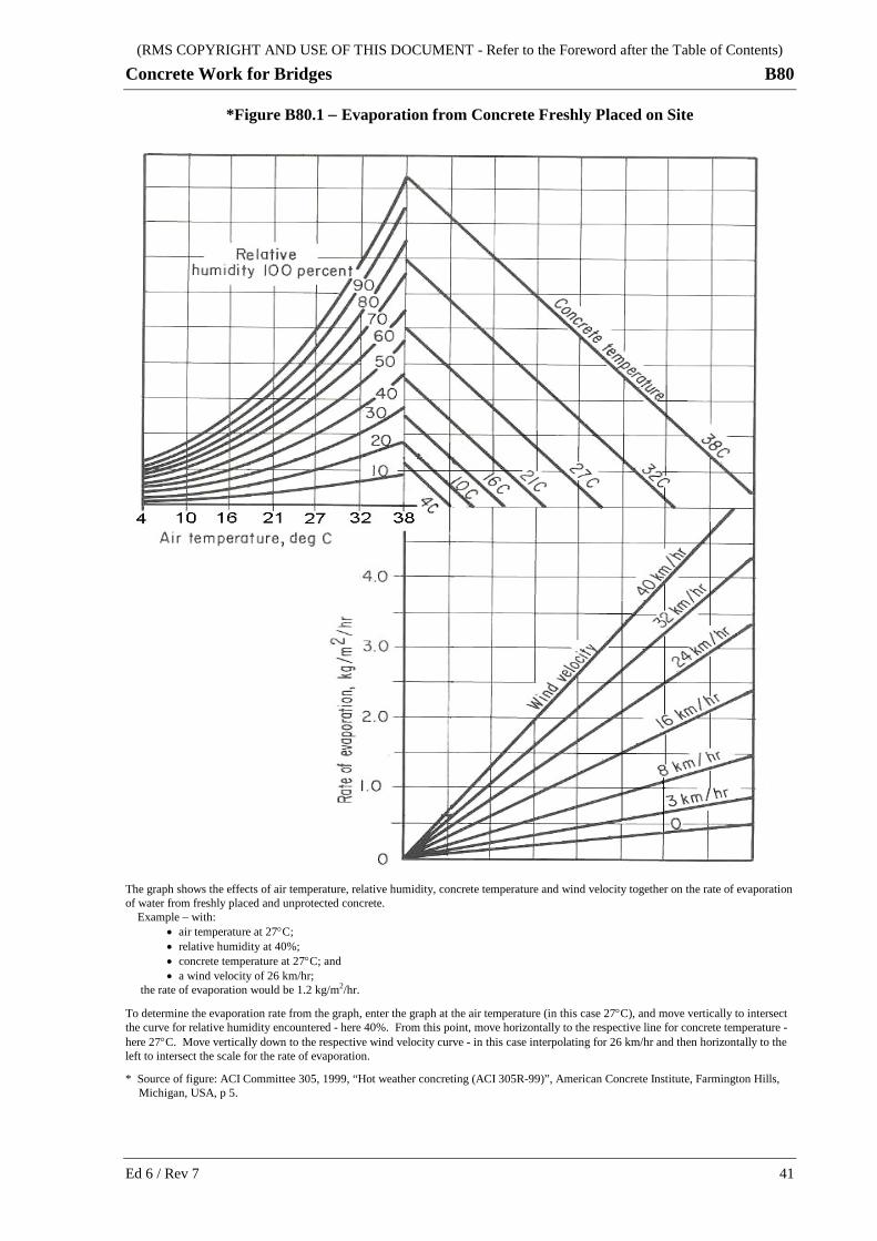
(RMS COPYRIGHT AND USE OF THIS DOCUMENT - Refer to the Foreword after the Table of Contents)
Concrete Work for Bridges B80
*Figure B80.1 − Evaporation from Concrete Freshly Placed on Site
The graph shows the effects of air temperature, relative humidity, concrete temperature and wind velocity together on the rate of evaporation of water from freshly placed and unprotected concrete. Example – with: • air temperature at 27°C; • relative humidity at 40%; • concrete temperature at 27°C; and • a wind velocity of 26 km/hr; the rate of evaporation would be 1.2 kg/m2/hr.
To determine the evaporation rate from the graph, enter the graph at the air temperature (in this case 27°C), and move vertically to intersect the curve for relative humidity encountered - here 40%. From this point, move horizontally to the respective line for concrete temperature - here 27°C. Move vertically down to the respective wind velocity curve - in this case interpolating for 26 km/hr and then horizontally to the left to intersect the scale for the rate of evaporation.
* Source of figure: ACI Committee 305, 1999, “Hot weather concreting (ACI 305R-99)”, American Concrete Institute, Farmington Hills, Michigan, USA, p 5.
Ed 6 / Rev 7 41

(RMS COPYRIGHT AND USE OF THIS DOCUMENT - Refer to the Foreword after the Table of Contents)
B80 Concrete Work for Bridges
7.9 PREPARATION OF SURFACE OF CONSTRUCTION JOINTS
Deliberately roughen the surface of concrete at construction joints to a pronounced profile with a surface roughness not less than 3 mm. Remove loose aggregate particles and laitance. Prior to placing the adjoining concrete, clean the surface of the construction joint and the projecting reinforcement and saturate the concrete surface with water conforming to the requirements of AS 1379. Remove all excess water and loose material prior to placing the adjoining concrete.
In marine or aggressive environments, remove salt or other contamination from the joint surface and reinforcement by using water under high pressure. Provide temporary openings in formwork to allow contaminated water to be removed.
7.10 ADDITIONAL REQUIREMENTS FOR VOIDED SLAB CONSTRUCTION
Voided slab construction comprises a cast-in-place deck slab having multiple longitudinal voids.
Carry out the placing of concrete in voided slabs in at least three stages as follows:
(a) to the bottom one third of the voids;
(b) to the top of the voids; and
(c) to the finished level.
The percentage of the total area covered by any one stage must be such that no concrete has reached its initial set before the overlying concrete is placed.
7.11 SCREEDING AND FINISHING OF UNFORMED SURFACES
7.11.1 Surfaces other than Deck and Approach Slabs
Unformed surfaces must be compacted and tamped to bring a layer of fines to the surface. Screed the surface to the specified levels and finish with a wooden or “magnesium” float to an even uniform surface. Leave construction joints rough in accordance with Clause 7.9.
When cracks appear before or during finishing, rework the concrete, using vibrators as required, where initial set has not yet occurred and refinish the surface with a wooden or “magnesium” float.
Do not delay at any location the completion of the finishing operation and the commencement of curing at that location.
7.11.2 Deck and Approach Slab Surfaces
7.11.2.1 Profile
For all types of deck and approach slab surfaces, whether concrete, asphalt or bitumen-sealed, screed the decks using vibrating screeds set on screeding guide rails.
Alternatively, and only when required by the deck and barrier or kerb layout and when permitted by the Principal or Annexure B80/A5, deck slabs may be screeded by experienced operators using power vibrating screeds and height pins. Use the wet screeding technique provided the concrete strips between height pins that are used to guide the screed are placed and compacted at the same time as the concrete between strips.
42 Ed 6 / Rev 7

(RMS COPYRIGHT AND USE OF THIS DOCUMENT - Refer to the Foreword after the Table of Contents)
Concrete Work for Bridges B80
Set screeding guide rails entirely above the concrete surface, unless they are removed on completion of screeding and before commencement of finishing. Make screeding guide rails sufficiently rigid to ensure that the correct finished deck surface levels shown on the Drawings and concrete cover will be produced on completion of the superstructure.
Supports for screeding guide rails and height pins must conform to Clause 6.7.4.
Screeding guide rails or height pin markings must be at levels to allow for take-up of formwork, deflections on removal of formwork, construction of subsequent stages of superstructure, deflection of girders, prestressing of the superstructure and any other factors which may change the deck levels during the construction of the bridge.
Height pin spacings both longitudinally and laterally must be equal to the length of the vibrating screed or three (3) metres, whichever is the lesser.
7.11.2.2 Technical Procedures
The Technical Procedures for finishing referred to in Annexure B80/D must include:
(a) evidence including survey results that the finishing method produces decks conforming to this Specification, and certification that non-conforming results have been included;
(b) type and rate of proposed evaporation retarders;
(c) details of proposed finishing aids;
(d) method of compaction of concrete adjacent to the guide rails;
(e) details including drawings of screeding guide rails or height pins and method of attachment to forms;
(f) method and timing of repairs at guide rail supports or height pins;
(g) timing for checking of profile using a straight edge; and
(h) type and size of allowances to be made for screeding guide rails or height pin marks for profile adjustments such as those mentioned in Clause 7.11.2.1.
7.11.2.3 Screeding
Place and compact the concrete in accordance with Clause 7.4. If a vibrating or power screed is used, bring the surface to the required level with a vibrating screed operating at a frequency of at least 100 Hz.
The final placement, redistribution and compaction of the top layer of deck concrete prior to or during screeding, must be such that the consolidation process is uniform throughout the deck area including areas adjacent to the screed rails or height pins. Keep sufficient surplus concrete in front of the screed to ensure full and uniform compaction to the deck surface.
Supplementary floating to bring fines to the surface is permissible.
Remove all parts of screeding guide rails or the top parts of height pins after final screeding and compact the disturbed areas to provide the concrete cover shown on the Drawings, within the tolerances given in Clause 6.9.
7.11.2.4 Protection of Surfaces
After screeding, protect the surface so that only excess bleed water is removed and no drying out of the surface occurs at any location. Conform to Clause 7.6.
Ed 6 / Rev 7 43

(RMS COPYRIGHT AND USE OF THIS DOCUMENT - Refer to the Foreword after the Table of Contents)
B80 Concrete Work for Bridges
7.11.2.5 Finishing
Do not carry out finishing until after the concrete has become sufficiently hardened to support the finishing operation. Complete all repairs to the concrete at the screeding guide rails and supports or height pin locations prior to the commencement of finishing.
Continue to protect the surface from drying out in accordance with Clause 7.11.2.4 during finishing and texturing.
Do not pour water onto the surface during finishing, but apply water mist sprays or aliphatic alcohols to prevent the concrete from drying out.
Provided they are not deleterious to the concrete surface, approved proprietary finishing aids may be used in adverse conditions when the concrete sheen is about to disappear, in which case apply the finishing aid without working it into the surface to restore the sheen.
Finishing must consist of either:
(a) wood or “magnesium” floating the surface; or
(b) steel trowelling followed by sweeping the surface transversely with a stiff-bristled yard broom, or using a suitable mechanical grooving device, to produce a uniformly roughened surface texture.
When cracks appear before or during finishing, rework the concrete using vibrators as required where initial set has not yet occurred, and refinish the surface with a wooden float.
There must be no delay between the completion of the finishing operation at any location and the commencement of curing at that location.
The texture depth of the surface must not be less than 0.90 mm when measured in accordance with Test Method RMS T240.
7.12 CURING
7.12.1 General
Apply curing in accordance with the approved curing regime nominated in Item (d) of Clause 3.8.2.
For all types of curing regimes, protect the concrete surface from extreme heat or cold and maintain at a temperature not less than 5°C throughout the curing period.
Wet cure all cast-in-place bridge decks and approach slabs for a minimum of 72 hours after finishing operations are completed. Further curing conforming to Annexure B80/E or to the approved curing regime of Item (d) of Clause 3.8.2 may be by either wet or sealed curing methods.
7.12.2 Wet Curing
Concrete surfaces must be wetted and completely covered with canvas, hessian, geofabric with plastic sheeting, or other suitable materials and be kept continuously wet. When used for vertical surfaces, keep these materials effectively wrapped and in place for the whole curing period. Water used for curing must conform to AS 1379 and be not more than 10°C cooler than the concrete surface.
Apply wet curing:
(a) to unformed surfaces immediately after the completion of all finishing operations;
44 Ed 6 / Rev 7

(RMS COPYRIGHT AND USE OF THIS DOCUMENT - Refer to the Foreword after the Table of Contents)
Concrete Work for Bridges B80
(b) in such a manner that staining of the formed surfaces does not produce a nonconforming finish;
(c) to formed surfaces immediately after the removal of the forms.
7.12.3 Sealed Curing
7.12.3.1 Retention of Formwork
Keep all parts of the formwork used under the sealed curing provision in place for the minimum periods nominated in Item (d) of Clause 3.8.2. Where it is proposed to strip part of or all the formwork before the required curing is completed, apply a curing compound or wet curing to the stripped members for the remainder of the curing period.
7.12.3.2 Curing Compounds
Curing compounds must conform to AS 3799 for the Classes and Types specified in Table B80.18.
No evidence of the curing compound must remain on any concrete surface exposed to view within a period of six (6) months from the date of application of the compound.
Table B80.18 - Classes and Types of Curing Compounds
Description of curing compound Class
to AS 3799
Minimum non-volatile content
to AS 1580 Method 301.1
Type to
AS 3799
Wax-based (Wax emulsion) A 30%
Resin-based (Hydrocarbon resin) B 30% 1-D
Waterborne emulsions Z 30%
The curing compound supplier must implement and maintain a quality management system conforming to AS/NZS ISO 9001 as a means of ensuring that the product conforms to this Specification.
For each curing compound proposed for use in the Works, provide the Principal a Certificate of Conformity from the supplier, supported by test certificates from a laboratory with appropriate NATA registration, certifying that the curing compound conforms to this Specification.
This Certificate of Conformity must relate only to the formulation on which the tests were made and must be valid for not more than three years from the date of issue. The test certificates must report the non-volatile content, the efficiency index and the density and must provide a reference for the infrared spectrum as determined in accordance with Test Method T1005.
For each batch delivered, provide the Principal a Certificate of Uniformity from the supplier, supported by uniformity testing on both non-volatile content and density in accordance with AS 3799 Clause 3.2, and on viscosity in accordance with AS 3799 Clause 3.1.5. Additionally, provide an infrared spectrum which matches the reference infrared spectrum. The Certificate of Uniformity must state that the same formulation has been used for the batch as is represented by the Certificate of Conformity.
Sample and test at a rate of not less than one test per 3000 litres, or part thereof, supplied.
Ed 6 / Rev 7 45

(RMS COPYRIGHT AND USE OF THIS DOCUMENT - Refer to the Foreword after the Table of Contents)
B80 Concrete Work for Bridges
Do not use wax emulsion on deck surfaces.
Apply the curing compound by a pressurised sprayer to give a uniform cover. The sprayer must incorporate a device for continuous agitation and mixing of the compound in its container during spraying.
Apply the curing compound using a fine spray at the rate stated on the Certificate of Conformity, or at a rate of 0.2 litres/m2 per coat, whichever is the greater. Check the application rate by calculating the amount of curing compound falling on felt mats, each approximately 0.25 m2 in area, placed on the concrete surface.
Apply the curing compound in two coats at the full rate to form a continuous membrane over the whole concrete surface.
The time between the first and second coat must be in accordance with the manufacturer's recommendation, or on the basis of a trial application.
Apply the curing compound to unformed surfaces immediately after completion of all finishing operations, and to formed surfaces within half an hour of the removal of formwork from the section.
Maintain the curing membrane intact after its initial application, for the period nominated in Item (d) of Clause 3.8.2. Make good any damage to the curing membrane by respraying the affected areas.
7.12.3.3 Plastic Wrapping
As an alternative to curing compounds, carry out sealed curing using tight, fully sealed plastic wrapping to prevent moisture loss from the concrete surface. Make good any damage to the wrapping by repairing the affected areas.
7.12.4 Heat Accelerated Curing
7.12.4.1 General
Heat accelerated curing must conform to the following:
(a) At the end of the presetting period (i.e. the interval between placing the last concrete and commencement of heat application) the concrete maturity or time elapsed must be the greater of 50°C.hrs or two hours respectively, and time elapsed must not be longer than five hours, unless wet curing is applied in the interim period prior to its application.
(b) Keep unformed exposed concrete surfaces wet with a relative humidity exceeding 98% at all times after the presetting period and until the completion of the heat curing. Provide evidence of this to the Principal.
(c) The rate at which the temperature of the concrete increases must not exceed 24°C per hour.
(d) The maximum temperature of the concrete during and after the application of heat must not exceed 70°C for all concrete exposure classifications.
(e) After completion of curing, allow the concrete to cool gradually and evenly. Do not expose the concrete to the surrounding environment or operate on it in any way until the temperature at the surface of the concrete has fallen to within 40°C of the ambient temperature.
46 Ed 6 / Rev 7

(RMS COPYRIGHT AND USE OF THIS DOCUMENT - Refer to the Foreword after the Table of Contents)
Concrete Work for Bridges B80
(f) Record maximum and minimum temperatures and temperature variations with time using a suitable thermograph taking reading at intervals not exceeding 15 minutes.
(g) For Durability Provision B only, keep the concrete at a temperature, T (°C) of not less than 50°C, for a period, P (hours), so that the result of the multiplication P times T is not less than 350°C.hours.
7.12.4.2 Steam Curing – Additional requirements
Use distribution pipes to assist in the uniform distribution of heat. Arrange the distribution pipes in such a manner and/or protect the concrete members in such a way that steam will not be blown directly against the concrete, or cause uneven heating of the members at any point.
Keep the enclosing arrangements sufficiently airtight during the whole period of steam curing to prevent the entry of cool air at any time.
Cure the associated concrete test cylinders by placing the cylinders within the enclosure in a position adjacent to the lower face of the structural units they represent. Locate the cylinders midway between steam entry points and at least half the width of the structural unit from these points. Do not place the cylinders on top of the structural units or on the steam jet lines or in line with any steam jets.
7.13 SLIPFORMED BARRIERS
Concrete barriers must not be slipformed.
7.14 CONCRETING OF DECK JOINT BLOCKOUTS
Where concreting of deck joint blockouts occurs after concreting of the bridge deck and the space between the blockout and the joint components is not sufficient to place and compact concrete, fill the blockouts using a flowable mortar with 28 day compressive strength not less than 60 MPa and shrinkage of not more than 500 microstrain at 3 weeks or 700 microstrain at 8 weeks. The mortar must contain aggregate conforming to Clauses 2.4.1 and 2.4.3.
Prepare the blockout for concreting strictly in conformity with Clause 7.9.
7.15 EARLY TRAFFICKING OF BRIDGE DECKS
Strictly control trafficking of bridge decks to prevent damage to new and curing concrete. Non-essential traffic must not access the deck until the specified 28 day compressive strength of the concrete is reached or the curing is completed, whichever occurs later.
Control access by essential traffic as follows:
(a) Equipment not exceeding 0.5 tonnes in weight may access the deck after 50% and before 75% of the specified 28 day compressive strength of the deck concrete is reached.
(b) Other equipment must not access the deck until 75% of the specified 28 day compressive strength of the deck concrete is reached, as follows:
(i) Maximum axle loads: 5.0 tonnes single, 8.0 tonnes tandem, 9.0 tonnes triaxle;
(ii) Tracked vehicles: maximum 15 tonnes/m2 pressure over the track area, providing the concrete is protected from surface damage.
Ed 6 / Rev 7 47

(RMS COPYRIGHT AND USE OF THIS DOCUMENT - Refer to the Foreword after the Table of Contents)
B80 Concrete Work for Bridges
Carry out in-place strength assessment in accordance with Clause 8.2 at a frequency to suit your construction program. All concrete placed using the same concrete mix for which the strength versus age relationship has been determined may be assumed to have the same strength versus age relationship providing the placement and air temperatures are similar. Otherwise, adjust the strength for the actual temperatures at the site.
HOLD POINT
Process Held: Early trafficking of concrete bridge deck.
Submission Details: Strength versus age relationship of concrete and evidence of completion of curing, with supporting test results.
Release of Hold Point: The Principal will consider the submitted documents, prior to authorising the release of the Hold Point within 2 working days of receipt of the documents.
Make good any damage arising from early trafficking of the bridge deck at no cost to the Principal.
8 PROPERTIES OF HARDENED CONCRETE
8.1 GENERAL
The methods and frequencies of sampling and testing of concrete for compressive strength, compaction, cover and other properties during the progress of the work must be in accordance with Annexure B80/L.
Do not take cores in concrete bridge decks or other bridge members without the Principal’s approval.
Use non-destructive tests to investigate concrete of observed or suspect quality, and take cores only to confirm findings of nonconforming concrete. Select coring locations to avoid reinforcement and wheel paths and where possible take cores in areas that will subsequently be covered with concrete.
Scabble and clean core holes and restore using a 10 mm maximum nominal aggregate size concrete mix of the same quality as the material from which the core was cut. Place, finish and cure the concrete in such a manner so as to produce no visible cracks.
The surface of the restored hole must be similar to the surrounding surface in texture and colour.
8.2 COMPRESSIVE STRENGTH
Determine the compressive strength of the concrete in accordance with Annexure B80/L Clause L4.
For the purpose of this Clause, the Representative Concrete Strength (RCS) is defined as either the age adjusted strength of concrete cylinders or, when applicable, the age adjusted strength of cores cut from the Works, in accordance with Annexure B80/L Clauses L3 and L4.
Concrete must be considered nonconforming where the RCS is less than fc.min determined in accordance with Clause 3.5. Refer to Annexure B80/B for resolution of nonconformities.
Any concrete with the RCS exceeding 100 MPa must be identified as nonconforming.
48 Ed 6 / Rev 7
(RMS COPYRIGHT AND USE OF THIS DOCUMENT - Refer to the Foreword after the Table of Contents)
Concrete Work for Bridges B80
8.3 COMPACTION
The relative compaction, determined as the percentage ratio of the unit mass of the sample cores to the unit mass of the representative cylinders for the concrete area from which the cores are cut, must be at least 98%. Any concrete failing to meet this requirement must be identified as nonconforming.
8.4 COVER
When required by the Principal, carry out a cover measurement survey of reinforced and precast concrete members in accordance with Clause L6 of Annexure B80/L or as directed by the Principal.
Any concrete members failing to conform to Clause L6.2.3 of Annexure B80/L must be identified as nonconforming and marked and mapped to identify the nonconforming locations.
All individual cover survey results which indicate a cover less than 75% of the specified cover must be identified and reported to the Principal together with the cover map and the proposed corrective action to rectify each nonconformity.
Ed 6 / Rev 7 49
(RMS COPYRIGHT AND USE OF THIS DOCUMENT - Refer to the Foreword after the Table of Contents)
B80 Concrete Work for Bridges
ANNEXURE B80/A – PROJECT SPECIFIC REQUIREMENTS Refer to Clause 1.2.1.
A1 MEMBERS IN EXPOSURE CLASSIFICATION U
A1.1 General
Concrete members in exposure classification U must conform to Specification RMS B80 for the Base Exposure Classification and the additional requirements contained in this Annexure.
A1.2 Base Exposure Classification
The Base Exposure Classification, Nature of Exposure and Concrete Isolation requirements are contained in Table B80/A.1 or as specified on the Drawings.
Concrete quality, cover and other durability requirements for the Base Exposure Classification must conform to those specified for the corresponding exposure classification of AS 5100.5.
Where full isolation of concrete surface from the aggressive environment is mandatory, include details of the proposed isolation method with the concrete mix design submission.
Table B80/A.1
Parameters Project Specific
Base Exposure Classification:
B1 B2 C
Nature of Exposure:
Acid sulfate soil Soft or running water Others
Full Isolation of Concrete Surface from Aggressive Environment:
Not required Optional Mandatory
A1.3 Additional Requirements
Cement: ..........................................................................................................................................
Aggregate: ......................................................................................................................................
Admixtures: ...................................................................................................................................
Mandatory Durability Provision (A, B, either): .........................................................................
Others: ............................................................................................................................................
Note: For concretes requiring durability suitable for exposure classification C, e.g. for acid sulfate soils, but which are not in a chloride aggressive environment, the corrosion inhibitor is not required.
50 Ed 6 / Rev 7

(RMS COPYRIGHT AND USE OF THIS DOCUMENT - Refer to the Foreword after the Table of Contents)
Concrete Work for Bridges B80
A2 BRIDGE MEMBERS FOR WHICH SELF-COMPACTING CONCRETE IS PERMITTED (JOB SPECIFIC)
Refer to Clauses 3.6 and 7.8 and Annexure B80/G1.
Precast concrete members manufactured under controlled conditions in off-site precasting yards.
A3 FORMWORK CATEGORY C (JOB SPECIFIC)
Refer to Clause 5.2.4.
A4 SURFACE FINISH REQUIREMENTS (JOB SPECIFIC)
Refer to Clause 5.3.
A5 BRIDGE DECKS FOR WHICH SCREEDING USING VIBRATING POWER SCREEDS AND HEIGHT PINS IS PERMITTED (JOB SPECIFIC)
Refer to Clause 7.11.2.1.
Ed 6 / Rev 7 51

(RMS COPYRIGHT AND USE OF THIS DOCUMENT - Refer to the Foreword after the Table of Contents)
B80 Concrete Work for Bridges
ANNEXURE B80/B – RESOLUTION OF NONCONFORMITIES Refer to Clause 1.2.2.
Work and materials must be rejected unless they conform to the requirements of this Specification or, where permitted in this Annexure, are accepted with the specified deductions.
B1 COMPRESSIVE STRENGTH
B1.1 Cores
If the 28 day compressive strength of reinforced or unreinforced concrete as indicated by test specimens fails to reach the specified minimum 28 day compressive strength, submit to the Principal a request for testing specimens cut from the completed Works.
For prestressed work, the request must be accompanied by a certificate from an Engineer who is a member of Engineers Australia (or equivalent) and who is experienced in the design of prestressed concrete structures. The certificate must state that the proposed coring will not be detrimental to the prestressed concrete member.
B1.2 Conformity of Concrete
Concrete where the RCS is less than fc.min (refer to Clause 3.5) or greater than 100 MPa is nonconforming.
Where the RCS is less than fc.min but greater than or equal to 90% of fc.min, the concrete represented may be accepted by the Principal at his discretion. In such cases, and when the concrete is accepted by the Principal, the schedule rate for the nonconforming concrete must be reduced by the amount shown in Table B80/B.1.
Any deduction arising from deficiencies in concrete strength, as calculated from Table B80/B.1, apply to the proportion of the pour represented by the deficient result.
In the case of precast members the “schedule price” in Table B80/B.1 is taken to mean one half the priced unit rate for the members.
Table B80/B.1 - Deductions for Understrength Concrete
Deficiency in strength below fc.min Deduction
Up to 5% 2% of the schedule price for each 1% (or fraction thereof) deficiency in strength.
Over 5% and up to 10% 10% of the schedule price for the first 5% deficiency plus 5% of the schedule price for each 1% (or fraction thereof) deficiency in strength in excess of 5%.
52 Ed 6 / Rev 7
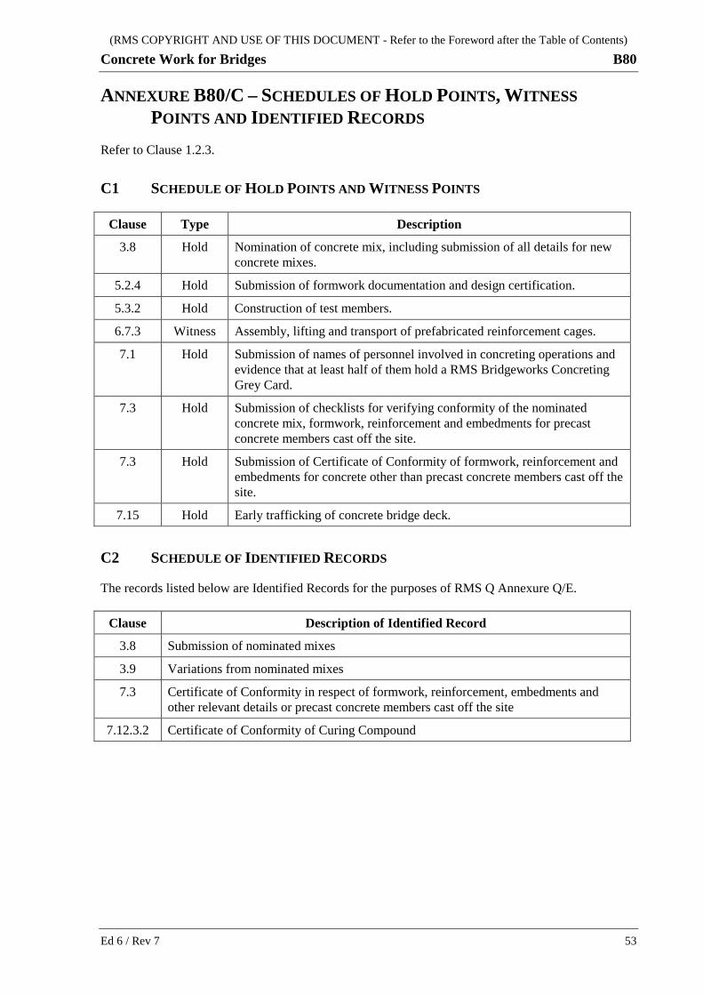
(RMS COPYRIGHT AND USE OF THIS DOCUMENT - Refer to the Foreword after the Table of Contents)
Concrete Work for Bridges B80
ANNEXURE B80/C – SCHEDULES OF HOLD POINTS, WITNESS POINTS AND IDENTIFIED RECORDS
Refer to Clause 1.2.3.
C1 SCHEDULE OF HOLD POINTS AND WITNESS POINTS
Clause Type Description
3.8 Hold Nomination of concrete mix, including submission of all details for new concrete mixes.
5.2.4 Hold Submission of formwork documentation and design certification.
5.3.2 Hold Construction of test members.
6.7.3 Witness Assembly, lifting and transport of prefabricated reinforcement cages.
7.1 Hold Submission of names of personnel involved in concreting operations and evidence that at least half of them hold a RMS Bridgeworks Concreting Grey Card.
7.3 Hold Submission of checklists for verifying conformity of the nominated concrete mix, formwork, reinforcement and embedments for precast concrete members cast off the site.
7.3 Hold Submission of Certificate of Conformity of formwork, reinforcement and embedments for concrete other than precast concrete members cast off the site.
7.15 Hold Early trafficking of concrete bridge deck.
C2 SCHEDULE OF IDENTIFIED RECORDS
The records listed below are Identified Records for the purposes of RMS Q Annexure Q/E.
Clause Description of Identified Record
3.8 Submission of nominated mixes
3.9 Variations from nominated mixes
7.3 Certificate of Conformity in respect of formwork, reinforcement, embedments and other relevant details or precast concrete members cast off the site
7.12.3.2 Certificate of Conformity of Curing Compound
Ed 6 / Rev 7 53

(RMS COPYRIGHT AND USE OF THIS DOCUMENT - Refer to the Foreword after the Table of Contents)
B80 Concrete Work for Bridges
ANNEXURE B80/D – PLANNING DOCUMENTS Refer to Clause 1.2.4.
The following documents are a summary of documents that must be included in the PROJECT QUALITY PLAN, and must be submitted to a timeline indicated by the project critical path, with due allowances for review by the Principal. The requirements of this Specification and others included in the Contract must be reviewed to determine additional documentation requirements.
The information to be submitted as part of the PROJECT QUALITY PLAN includes, but is not limited to, the following:
(a) Procedures for addition of corrosion inhibitors (refer to Clause 2.3.2);
(b) All concrete mix designs and trial mix reports (refer to Clause 3.8);
(c) Procedures for trialling and details of set retarding admixture to delay hydration (refer to Clause 4.3.5);
(d) Details of the design and construction of test members (refer to Clause 5.3.2);
(e) Details of the methods to be used in determining the stripping time of formwork other than by direct testing of representative cylinders (refer to Clause 5.9.2);
(f) Approved procedure for repair to minor surface imperfections (refer to Clause 5.10);
(g) Welding procedures and design of load bearing welds in reinforcement cages (refer to Clause 6.3.3);
(h) Details of the method of placing embedments (refer to Clause 6.7.5);
(i) Technical Procedures in accordance with Specification RMS Q for the placing, compacting, screeding, finishing and curing operations in Clause 7. The personnel required to carry out the operations together with proof of any relevant training and experience must be included.
As well as the methods for placing, the procedures must include the delivery method and placing rates for varying pour sizes.
The compaction procedures must include detailed plans for the use of vibrators in the concrete and the method for ensuring full compaction of the whole of the concrete member;
(j) Details of the methods to be used to prevent thermal cracking (refer to Clause 7.1);
(k) Name, qualifications and experience of the Concrete Supervisor for concrete pours other than precast members cast off the site (refer to Clause 7.3);
(l) Technical Procedures for the restriction of the evaporation rates (refer to Clause 7.6);
(m) Details of the method of fixing and removing screed guide rails or height pins (refer to Clause 7.11.2);
(n) Technical Procedures for deck finishing (refer to Clause 7.11.2);
(o) Verification of the conformity of a proposed heat accelerated curing method with the Specification requirements (refer to Clause 7.12.4);
(p) Procedures for supply and placement of self-compacting concrete (refer to Annexure B80/G);
(q) Identification of work Lots and name, qualifications and experience of technicians for cover surveys (refer to Annexure B80/L6).
54 Ed 6 / Rev 7

(RMS COPYRIGHT AND USE OF THIS DOCUMENT - Refer to the Foreword after the Table of Contents)
Concrete Work for Bridges B80
ANNEXURE B80/E – CURING PROVISION B Refer to Clause 3.4.2.
For the exposure classifications specified on the Drawings, the curing applied must be in accordance with Tables B80/E.1 (wet), B80/E.2 (sealed) and B80/E.3 (heat accelerated).
For formed surfaces, the wet curing provision is applicable only when the formwork is removed within 48 hours of completion of concrete placement, and the surface immediately wet cured.
Concrete made with blended cement containing amorphous silica must be wet cured only.
Notes for Tables B80/E.1, B80/E.2 and B80/E.3:
For the definition of cement, refer to Clause 1.3 “Definitions”
SL denotes Shrinkage Limited cement
BFS denotes ground granulated iron blast furnace slag blended cement
FA denotes fly ash blended cement
AS denotes amorphous silica blended cement
N/A Not applicable. Durability Provision B does not apply for this case
Applicable. Durability Provision B may apply for this case
Table B80/E.1 - Wet Curing
Exposure classification
Curing period (days)
SL cement
Blended cement containing BFS and/or FA
Blended cement containing AS
A 7 7 N/A
B1 7 7 N/A
B2 N/A 14 7
C N/A 14 7
U In accordance with Annexure B80/A1
Table B80/E.2 - Sealed Curing
Exposure classification
Curing period (days)
SL cement
Blended cement containing BFS and/or FA
A 7 7
B1 7 7
B2 N/A N/A
C N/A N/A
U In accordance with Annexure B80/A1
Ed 6 / Rev 7 55

(RMS COPYRIGHT AND USE OF THIS DOCUMENT - Refer to the Foreword after the Table of Contents)
B80 Concrete Work for Bridges
Table B80/E.3 - Heat Accelerated Curing
Exposure classification
Permissibility of curing
SL cement
Blended cement containing BFS and/or FA and/or AS
A
B1
B2 N/A
C N/A
U In accordance with Annexure B80/A1
56 Ed 6 / Rev 7

(RMS COPYRIGHT AND USE OF THIS DOCUMENT - Refer to the Foreword after the Table of Contents)
Concrete Work for Bridges B80
ANNEXURE B80/F – STAINLESS STEEL REINFORCEMENT Refer to Clause 6.
F1 GENERAL
All the requirements of this Specification apply to the supply, fabrication, transport, storage, assembly and fixing of stainless steel reinforcement, except where modified by this Annexure.
F2 DURABILITY
Where stainless steel reinforcement is used in members in exposure classification C, a corrosion inhibiter is not required.
F3 SUPPLY
F3.1 Quality Management System Requirements
The reinforcement material supplier must be certified by the UK Certification Authority for Reinforcing Steels for the production of stainless steel reinforcement materials.
F3.2 Materials
Stainless steel reinforcement must be deformed bars, deformed wire or welded wire fabric.
Stainless steel reinforcement must be strength grade 500 in accordance with Table 7, BS 6744:2001 and conform to designation 1.4362, 1.4429, 1.4436 or 1.4462 to BS 10088 (as identified by Table 5, BS 6744:2001). Uniform elongation must conform to AS/NZS 4671 for Grade 500N.
F4 FABRICATION AND ASSEMBLY
F4.1 Fabrication
The reinforcement fabricator must implement and maintain a quality management system in accordance with AS/NZS ISO 9001.
Tools for fabricating stainless steel reinforcement must not have been used and must not be used for other materials. Tools and processes for cutting stainless steel must not reduce the strength of the stainless steel reinforcement or cause contamination with grease, oil, iron or other steels.
F4.2 Bending
Tools for bending stainless steel reinforcement must not have been used and must not be used for other materials. Pins used for bending stainless steel must be made from stainless steel.
Do not heat stainless steel reinforcement for bending.
Do not field bend bars with diameters greater than 20 mm.
Ed 6 / Rev 7 57
(RMS COPYRIGHT AND USE OF THIS DOCUMENT - Refer to the Foreword after the Table of Contents)
B80 Concrete Work for Bridges
F4.3 Welding
Carry out welding only when permitted by the Principal in writing.
All welding for stainless steel reinforcement must comply with Specification RMS B203 and the following:
(a) Weld stainless steel reinforcement only in a welding shop set up for the purpose. Any such facility must maintain conditions that prevent any contamination of the stainless steel and any consumables and allows proper welding;
(b) Store, condition and handle all consumables in accordance with the bar manufacturer’s recommendations;
(c) Welding procedures and consumables must comply with the bar manufacturer’s recommendations. Welds must conform to Category 1B to AS 1554.6 Table 6.1.1. Assess defects in accordance with AS 1554.3 Sections 9 and 10. Examine welds using dye penetrant or magnetic particle examination methods. Treat any arc strikes as welds;
(d) Demonstrate that the weld does not result in the loss of ductility and corrosion resistance. Test welds in accordance with AS 1554.3 Clause 7.1 and Table 7.2;
(e) Keep the weld area clean and free of any contamination;
(f) Clean and passivate completed welds by stainless steel wire brushing and pickling to finish Category II to AS 1554.6 Table 6.2.1. Pickling compounds must be chloride free;
(g) Test welds and the welded bars in the vicinity of the welds for corrosion resistance against pitting and intergranular corrosion in accordance with AS 1554.6 Appendix E using a laboratory with appropriate NATA registration. Corrosion resistance testing must include qualification tests and be carried out on not less than 10% of all welds performed in the Works;
(h) Where any of the tested bars fails the corrosion resistance test, test all welds and bars in the vicinity of the welds for corrosion resistance.
F4.4 Splicing
Manufacture mechanical splices for stainless steel reinforcement from stainless steel conforming to designation 1.4362, 1.4429, 1.4436 or 1.4462 to BS 10088 (as identified by Table 5, BS 6744:2001).
F5 ASSEMBLY
Secure reinforcement in place by tying or tack welding.
Tie wire with stainless steel wire having a diameter of not less than 1.2 mm. Wire used to tie stainless steel must conform to designation 1.4362, 1.4429, 1.4436 or 1.4462 to BS 10088 (as identified by BS 6744:2001).
Perform tack welding in accordance with Clause F4.3.
58 Ed 6 / Rev 7

(RMS COPYRIGHT AND USE OF THIS DOCUMENT - Refer to the Foreword after the Table of Contents)
Concrete Work for Bridges B80
ANNEXURE B80/G – SELF-COMPACTING CONCRETE
G1 GENERAL
All the requirements of this Specification apply to the design, supply, delivery, placement and curing of self-compacting concrete except where modified by this Annexure.
Only supply self-compacting concrete for the specific bridge members listed in Annexure B80/A2.
For self-compacting concrete, where “slump” is specified in this Specification, use “slump flow spread” instead.
Prepare concrete test samples without mechanical or manual compaction.
G2 PERFORMANCE REQUIREMENTS
The fresh properties of self-compacting concrete must conform to Table B80/G1.
Table B80/G1 Fresh Properties of Self-Compacting Concrete
Property Test Method Criteria Notes
Filling ability
ASTM C1611 Spread: 550 – 800 mm Target Value ± 50mm may be used
Stability ASTM C1611 VSI rating: < 2 VSI rating of 2 may be acceptable depending on the type of concrete pour
EN 12350-11 Sieved portion: ≤ 15 %
Required during trial mixing
ASTM C1712 Penetration: ≤ 10mm Penetration depth ≤ 15mm may be acceptable depending on the type of concrete pour
Passing ability
ASTM C1621 Δ Spread: 25 – 50 mm Complete test within 6 minutes of ASTM C1611 to harmonise results
EN 12350-12 Δ Height: ≤ 15 mm Difference between height at centre and mean height just outside J-ring.
Required during trial mixing.
Viscosity ASTM C1611 T500: 2 – 5 seconds Gives indication on consistency between batches
G3 TRIAL MIXES
Where self-compacting concrete is proposed, choose the mix composition and proportions carefully to satisfy project specific performance requirements, taking into account the placement method, and the possible worst case arising from the variability in the batching of the mix constituents.
Where self-compacting concrete is trialled, submit:
(a) Spread and corresponding nominated slump flow spread instead of slump;
(b) Time to 500 mm slump flow spread, T500, and corresponding nominated T500 range;
Ed 6 / Rev 7 59

(RMS COPYRIGHT AND USE OF THIS DOCUMENT - Refer to the Foreword after the Table of Contents)
B80 Concrete Work for Bridges
(c) Visual stability index (VSI) rating and nominated VSI requirement;
(d) Passing ability values and corresponding nominated passing ability values;
(e) Static segregation percentage and corresponding nominated static segregation percentage;
(f) Penetration depth and corresponding nominated degree of static segregation resistance.
G4 TEST MEMBERS
Where a test member is required under Clause 5.3.2, conform to the following:
(a) For columns, the test member must consist of a column not less than the height of the column in question or 6 m, whichever is less, with similar corner detailing and steel reinforcement layout;
(b) For other members, replicate the most complex part of the member;
(c) Cut the concreted test member as directed by the Principal to demonstrate that segregation has not occurred.
G5 FORMWORK DESIGN
Where self-compacting concrete is supplied and when placement time is less than 1.5 hours, design the formwork, including support and fixing systems, for full hydrostatic concrete pressure. Where greater times for placement are proposed, determine the rate of stiffening of the concrete under the conditions for placement by experiment and design the formwork accordingly.
G6 SUPPLY, DELIVERY, PLACEMENT AND CURING
Where self-compacting concrete is supplied, include the following additional details on the concrete batch delivery dockets:
• Target value and accepted range for slump flow, instead of nominated slump.
• Instructions for adding admixtures at the site to adjust workability.
Where self-compacting concrete is supplied, do not add water to the mixed batch in-transit or at the site. High-range water reducers may be added to adjust deformability or flowability at the site at a dosage determined and agreed prior to full production.
For all operations where self-compacting concrete is approved, implement rigorous production control especially of water and admixtures during concrete batching and delivery in accordance with CIA Z40 or SCC 028.
Where self-compacting concrete is supplied by pump for columns and shafts, to prevent segregation, keep the end of the pump hose initially as close as possible to the bottom of the pour to limit the free fall height, and keep it submerged at least 300 mm as the pour progresses upwards.
Keep the distance of horizontal flow less than 10 m. Do not exceed the rate of placement specified in the formwork design for the placement conditions.
Although compaction is not normally required for self-compacting concrete, apply supplementary compaction as required to ensure full compaction of the member.
Where compaction is required for complex forms or thin members with congested reinforcement, commence placement from the lowest point of the formwork and progress to the highest point, and apply compaction only as required to achieve the specified concrete finish and properties.
60 Ed 6 / Rev 7
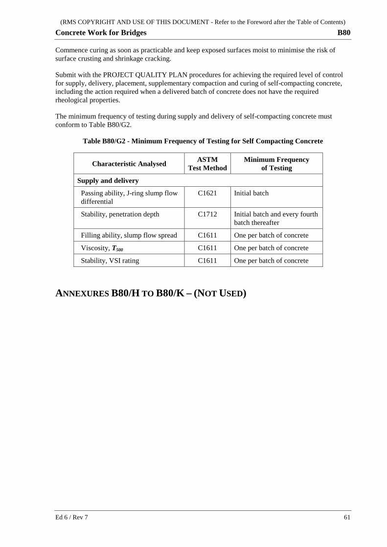
(RMS COPYRIGHT AND USE OF THIS DOCUMENT - Refer to the Foreword after the Table of Contents)
Concrete Work for Bridges B80
Commence curing as soon as practicable and keep exposed surfaces moist to minimise the risk of surface crusting and shrinkage cracking.
Submit with the PROJECT QUALITY PLAN procedures for achieving the required level of control for supply, delivery, placement, supplementary compaction and curing of self-compacting concrete, including the action required when a delivered batch of concrete does not have the required rheological properties.
The minimum frequency of testing during supply and delivery of self-compacting concrete must conform to Table B80/G2.
Table B80/G2 - Minimum Frequency of Testing for Self Compacting Concrete
Characteristic Analysed ASTM Test Method
Minimum Frequency of Testing
Supply and delivery
Passing ability, J-ring slump flow differential
C1621 Initial batch
Stability, penetration depth C1712 Initial batch and every fourth batch thereafter
Filling ability, slump flow spread C1611 One per batch of concrete
Viscosity, T500 C1611 One per batch of concrete
Stability, VSI rating C1611 One per batch of concrete
ANNEXURES B80/H TO B80/K – (NOT USED)
Ed 6 / Rev 7 61
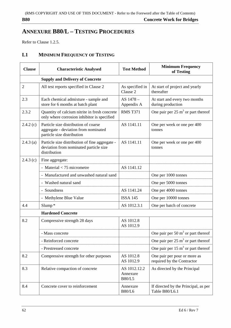
(RMS COPYRIGHT AND USE OF THIS DOCUMENT - Refer to the Foreword after the Table of Contents)
B80 Concrete Work for Bridges
ANNEXURE B80/L – TESTING PROCEDURES Refer to Clause 1.2.5.
L1 MINIMUM FREQUENCY OF TESTING
Clause Characteristic Analysed Test Method Minimum Frequency of Testing
Supply and Delivery of Concrete
2 All test reports specified in Clause 2 As specified in Clause 2
At start of project and yearly thereafter
2.3 Each chemical admixture - sample and store for 6 months at batch plant
AS 1478 – Appendix A
At start and every two months during production
2.3.2 Quantity of calcium nitrite in fresh concrete only where corrosion inhibitor is specified
RMS T371 One pair per 25 m3 or part thereof
2.4.2 (c) Particle size distribution of coarse aggregate - deviation from nominated particle size distribution
AS 1141.11 One per week or one per 400 tonnes
2.4.3 (a) Particle size distribution of fine aggregate - deviation from nominated particle size distribution
AS 1141.11 One per week or one per 400 tonnes
2.4.3 (c) Fine aggregate:
- Material < 75 micrometre AS 1141.12
- Manufactured and unwashed natural sand One per 1000 tonnes
- Washed natural sand One per 5000 tonnes
- Soundness AS 1141.24 One per 4000 tonnes
- Methylene Blue Value ISSA 145 One per 10000 tonnes
4.4 Slump * AS 1012.3.1 One per batch of concrete
Hardened Concrete
8.2 Compressive strength 28 days AS 1012.8 AS 1012.9
- Mass concrete One pair per 50 m3 or part thereof
- Reinforced concrete One pair per 25 m3 or part thereof
- Prestressed concrete One pair per 15 m3 or part thereof
8.2 Compressive strength for other purposes AS 1012.8 AS 1012.9
One pair per pour or more as required by the Contractor
8.3 Relative compaction of concrete AS 1012.12.2 Annexure B80/L5
As directed by the Principal
8.4 Concrete cover to reinforcement Annexure B80/L6
If directed by the Principal, as per Table B80/L6.1
62 Ed 6 / Rev 7

(RMS COPYRIGHT AND USE OF THIS DOCUMENT - Refer to the Foreword after the Table of Contents)
Concrete Work for Bridges B80
* For concrete containing a high range water reducer, requirements for test method and minimum frequency of testing must be applied to both initial and final slump.
L2 MOULDING OF SAMPLES
Moulded concrete specimens must be standard cylinders moulded in accordance with the requirements and procedure of AS 1012.8.1 using rodding only.
L3 SPECIMENS CUT FROM THE WORKS (CORES)
When directed by the Principal, core specimens must be cut by means of a core drill, wet pre-treated and tested in accordance with AS 1012.14. The corrected (for length to diameter ratio) strength so determined must be adjusted for age by dividing the result by the factors shown in Table B80/L.1.
Do not cut reinforcement during extracting core specimens. Prior to coring, do cover meter survey at representative locations to identify the rebar positions. Do not test cores containing reinforcement and replacement cores must be cut at new locations.
L4 COMPRESSIVE STRENGTH
L4.1 Testing
The compressive strength of the concrete represented by a pair of specimens moulded from one sample, cured and tested in accordance with AS 1012, is the average strength of the two specimens unless the two results differ by more than 10% of their average, in which case the higher result must be taken as the strength of the concrete.
L4.2 Adjustment for Age of Specimen
Should any specimen be tested more than 28 days after moulding, the equivalent 28 day strength is the test strength divided by the age factor given in Table B80/L.1. Age adjustment factors are given for concrete made with General Purpose and Blended cement. For intermediate ages, the factor must be determined on a pro-rata basis.
Table B80/L.1 - Factors for Age of Specimens
Age of specimen at time of test (days)
Age factor
General Purpose cement Blended cement
28 1.00 1.00
56 1.08 1.19
112 1.14 1.33
224 1.22 1.42
365 or greater 1.25 1.45
Ed 6 / Rev 7 63

(RMS COPYRIGHT AND USE OF THIS DOCUMENT - Refer to the Foreword after the Table of Contents)
B80 Concrete Work for Bridges
L5 COMPACTION
L5.1 Cores
Take cores in the deck and elsewhere only as and when directed by the Principal. The locations of the cores, which are subject to the agreement of the Principal, must be selected to clear any reinforcement or other embedments.
Test specimens for determining the relative compaction of concrete must be cores of nominal diameter 75 mm, cut in accordance with the requirements of Clause L3 except that the minimum concrete age for coring must be:
(a) four (4) days from May to December inclusive; or
(b) two (2) days from December to April inclusive.
Within two (2) hours of coring, the cores must be placed in either a tank of lime saturated water or individual plastic bags, sealed to prevent water loss and stored in the shade.
Cores must not be subjected to temperatures:
(i) in excess of the ambient temperature or 28°C, whichever is higher; or
(ii) less than 10°C.
L5.2 Testing
Determine the unit mass of representative cylinders for concrete compaction at an age of between four (4) and seven (7) days in accordance with AS 1012.12.2 and the following conditions:
(i) Testing of the representative cylinders must be in the saturated surface-dry condition without dressing of voids, in accordance with Test Method RMS T368; and
(ii) The unit mass for a pair of representative cylinders must be the average of the two results unless they differ by more than 20 kg/m3, in which case the higher result must represent the unit mass of the pair.
Determine the unit mass of the cores and report all results in accordance with AS 1012.12.2 and the following:
(a) assess cores in accordance with Test Method RMS T368 for excessive voids and, if warranted, dress voids prior to testing;
(b) wet conditioning in AS 1012.12.2 Clause 6(c) may be extended from 24 hours to 3 days;
(c) the concrete age at testing must be between three (3) and seven (7) days;
(d) the full depth of the core must be tested except that:
(i) non-concrete materials such as bitumen must be removed, and
(ii) up to 20 mm of concrete may be removed from each end of the core;
(e) report the height and diameter of the core, as tested; and
(f) round individual results for unit mass to the nearest 10 kg/m3 in accordance with AS 1012.12.2.
The unit mass of the cores is the average of the test results (rounded to the nearest 10 kg/m3) unless they differ by more than 20 kg/m3, in which case the lower result applies.
64 Ed 6 / Rev 7

(RMS COPYRIGHT AND USE OF THIS DOCUMENT - Refer to the Foreword after the Table of Contents)
Concrete Work for Bridges B80
L6 COVER
L6.1 Testing
When directed by the Principal, test concrete cover in discrete Lots at the minimum frequency specified in Table B80/L6.1 or as directed by the Principal.
L6.1.1 Identification of Work Lots
A Lot must be representative of concrete bridge members or products produced under essentially constant conditions. Discrete portions of a Lot that are visually non-homogeneous and/or non-representative must be excluded and either treated as separate Lots or repaired/replaced to achieve conformity of this Specification.
The size of a Lot must not exceed the extent of the day’s concrete pour except where directed by the Principal.
Describe in the PROJECT QUALITY PLAN how the Lot is to be identified in the field or the pre-casting yard.
Determine the bounds of each Lot before testing. Set the bounds of each Lot and use statistical methods to determine test locations and compliance. Demonstrate the relationship of the boundaries of all adjacent/following Lots to confirm that the Lots will represent the bridge members or products being examined.
Give each Lot a unique Lot number. Use this Lot number as an identifier on all quality records. The Lot numbering system must be compatible with any activity numbering system used for the bridge construction operations. Record the Lot number on a register that indicates the three-dimensional location of the Lot. Include in the PROJECT QUALITY PLAN details of the Lot numbering system and the place where the Lot register is kept. Record the start, finish, lateral and height locations. When the Lot number does not indicate the location of the Lot, agree the method for identification of the Lot with the Principal.
L6.1.2 Exclusion from Work Lots
Portions of a concrete bridge member or product that will be covered by subsequent concreting operations my be excluded from the Lot.
L6.1.3 Technicians
Include in the PROJECT QUALITY PLAN the name(s) of the technician(s) with details of qualifications and experience in concrete cover surveys. The technician(s) must have a proven record in the use of cover meters and must conduct all stages of the survey.
L6.1.4 Reports
Concrete cover survey reports must be provided to the Principal within 5 working days of the Principal’s direction. Reports must be prepared in a format acceptable to the Principal and must contain Lot numbers, test locations, measurement results, standard deviations on progressive accumulated results, progressive maximum and minimum value of attribute (Q) and comments on compliance with this Specification and the technician’s name and signature.
Ed 6 / Rev 7 65
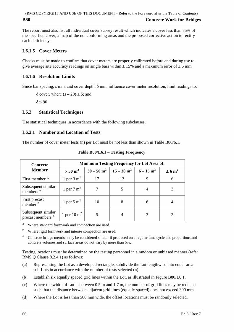
(RMS COPYRIGHT AND USE OF THIS DOCUMENT - Refer to the Foreword after the Table of Contents)
B80 Concrete Work for Bridges
The report must also list all individual cover survey result which indicates a cover less than 75% of the specified cover, a map of the nonconforming areas and the proposed corrective action to rectify each deficiency.
L6.1.5 Cover Meters
Checks must be made to confirm that cover meters are properly calibrated before and during use to give average site accuracy readings on single bars within ± 15% and a maximum error of ± 5 mm.
L6.1.6 Resolution Limits
Since bar spacing, s mm, and cover depth, δ mm, influence cover meter resolution, limit readings to:
δ cover, where (s – 20) ≥ δ; and
δ ≤ 90
L6.2 Statistical Techniques
Use statistical techniques in accordance with the following subclauses.
L6.2.1 Number and Location of Tests
The number of cover meter tests (n) per Lot must be not less than shown in Table B80/6.1.
Table B80/L6.1 – Testing Frequency
Concrete Member
Minimum Testing Frequency for Lot Area of:
> 50 m2 30 – 50 m2 15 – 30 m2 6 – 15 m2 ≤ 6 m2
First member * 1 per 3 m2 17 13 9 6
Subsequent similar members ∆ 1 per 7 m2 7 5 4 3
First precast member # 1 per 5 m2 10 8 6 4
Subsequent similar precast members ∆ 1 per 10 m2 5 4 3 2
* Where standard formwork and compaction are used. # Where rigid formwork and intense compaction are used. ∆ Concrete bridge members my be considered similar if produced on a regular time cycle and proportions and
concrete volumes and surface areas do not vary by more than 5%.
Testing locations must be determined by the testing personnel in a random or unbiased manner (refer RMS Q Clause 8.2.4.1) as follows:
(a) Representing the Lot as a developed rectangle, subdivide the Lot lengthwise into equal-area sub-Lots in accordance with the number of tests selected (n).
(b) Establish six equally spaced grid lines within the Lot, as illustrated in Figure B80/L6.1.
(c) Where the width of Lot is between 0.5 m and 1.7 m, the number of grid lines may be reduced such that the distance between adjacent grid lines (equally spaced) does not exceed 300 mm.
(d) Where the Lot is less than 500 mm wide, the offset locations must be randomly selected.
66 Ed 6 / Rev 7

(RMS COPYRIGHT AND USE OF THIS DOCUMENT - Refer to the Foreword after the Table of Contents)
Concrete Work for Bridges B80
(e) Determine the order of testing of the six lines by selecting a six digit number from Table B80/L6.2. A starting point on the table (e.g. 1st number, block 6D (= 415236)) will be advised by the Principal prior to the commencement of testing. The numbers are to be used sequentially down the Table until further notice from the Principal, starting at the point advised by the Principal, and selecting a new number for each Lot tested.
(f) Where there are less than 6 grid lines in the Lot, delete from the random number selected from Table B80/L6.2, the numerals that exceed the number of gridlines in the Lot (e.g. in the above example, where there are only 4 grid lines, the sequence is 4123).
(g) If for any reason the starting point has not been advised then it must be the first number in the block determined, by the following method, from the date on which testing is first undertaken:
Select column: A B C D
For: January February March April
For: May June July August
For: September December December December
Day: select a row on the basis of: 1st, 11th, 21st, 31st = Row 1; 2nd, 12th, 22nd = Row 2; etc.
(h) For each block in Table B80/L6.2, use the Fraction R at the right of the relevant random number. Length coordinate for testing location in sub-Lot 1 = RL/n.
(i) Record the Lot number on Table B80/L6.2 to the right of the applicable random number and indicate the date of the testing on the Table.
(j) For the testing location in the next sub-Lot: Add L/n to the previous length coordinate. Go to the next line as indicated by the six-digit number. (e.g. if the number is 415236 the first line tested is 4, followed by 1, 5, 3, 2 and 6 and the
sample locations are as shown in Figure B80/L6.1).
(k) If the Lot requires more than six testing locations, repeat the sequence using the same Grid Line Sequence and Fraction R to provide as many additional locations as are required.
(l) Outer bar steel reinforcement may not exist directly under each derived testing location and testing personnel may then offset the location marginally to obtain a reading.
(m) All test locations must be marked with weatherproof chalk or crayon to facilitate audit testing.
Ed 6 / Rev 7 67

(RMS COPYRIGHT AND USE OF THIS DOCUMENT - Refer to the Foreword after the Table of Contents)
B80 Concrete Work for Bridges
L/n
Testingl Location
L = length of lot
Sublot 1 Sublot 2 L/n L/n
RL/n
Figure B80/L6.1 Testing Locations for the Developed Lot
100 mm
100 mm
Sublot n
68 Ed 6 / Rev 7

(RMS COPYRIGHT AND USE OF THIS DOCUMENT - Refer to the Foreword after the Table of Contents)
Concrete Work for Bridges B80
Table B80/L6.2 — Random Grid Line Sequences (and Random Fraction R)
A B C D Sequence R Lot No. Sequence R Lot No. Sequence R Lot No. Sequence R Lot No.
1 531426 .91 245136 .01 532461 .25 425316 .17 634125 .15 641532 .46 431652 .95 613254 .38 165243 .96 265413 .29 124563 .76 352641 .32 452613 .61 236541 .49 324651 .84 546123 .30
2 612345 .14 625413 .76 514236 .68 364251 .07 246135 .72 145632 .76 643215 .45 621534 .85 316245 .86 516342 .21 546312 .50 156243 .03 253416 .01 615243 .04 526413 .29 514326 .63
3 342615 .95 162543 .70 263541 .69 145236 .63 352146 .85 624315 .43 435612 .01 412536 .97 245613 .38 526314 .02 356412 .23 614253 .01 451623 .08 631245 .13 163425 .07 652143 .11
4 135624 .49 213465 .97 356142 .29 163254 .77 621354 .45 536214 .36 325461 .88 342165 .37 613425 .34 425136 .78 125463 .91 564231 .45 456321 .35 514623 .75 436251 .61 326451 .67
5 245631 .44 214563 .43 124356 .45 325164 .83 516234 .52 425631 .23 536412 .64 246153 .08 462513 .83 645213 .86 653124 .32 516423 .94 532146 .83 531624 .19 453612 .93 125643 .54
6 264531 .16 654132 .64 153462 .19 415236 .16 321456 .07 352416 .64 526431 .42 524163 .54 426135 .52 436125 .63 125436 .40 641352 .04 154632 .64 625341 .20 613452 .36 251436 .17
7 512463 .13 362451 .16 125346 .12 136542 .09 264315 .85 251634 .99 431265 .10 132546 .18 453216 .15 136254 .72 425361 .79 145326 .74 532164 .12 523641 .85 614352 .02 245361 .76
8 631524 .33 634521 .23 632154 .48 264351 .72 532614 .01 153264 .35 452316 .16 465312 .57 253641 .28 152634 .53 153642 .22 635412 .01 261453 .75 624135 .08 423561 .87 312645 .76
9 235461 .68 532164 .63 652431 .90 516432 .88 654321 .19 415362 .05 613542 .64 461523 .31 614523 .13 316524 .48 463521 .66 236415 .92 361524 .51 432165 .54 621435 .39 346512 .43
10 152643 .04 365142 .29 146253 .97 241365 .09 625314 .43 315624 .90 162354 .96 452631 .42 346251 .54 142356 .60 461352 .62 241356 .45 513246 .70 513624 .74 163542 .61 352614 .97
Ed 6 / Rev 7 69

(RMS COPYRIGHT AND USE OF THIS DOCUMENT - Refer to the Foreword after the Table of Contents)
B80 Concrete Work for Bridges
L6.2.2 Method for Statistical Calculation for Conformity of Lots
When acceptance criteria specify a maximum and/or minimum characteristic value of attribute (Q), QU and/or QL must be used to determine Q.
The calculation of the characteristic value of attribute (Q) for the Lot/s must be as follows:
QU x ks= +
QL x ks= −
where x = arithmetic mean of attribute test results for all Lots and sub-Lots (mm)
s = standard deviation of Lots and sub-Lots attribute test results
( )∑= −
−=
n
i
i
nxx
1
2
1
k = acceptance constant from Table B80/L6.3 (based on 10% producer's risk)
Table B80/L6.3 - Acceptance Constant k
No of tests 3 4 5 6 7 8 9 10 - 14 15 - 19 20 +
k 0.52 0.62 0.67 0.72 0.75 0.78 0.81 0.83 0.90 0.95
L6.2.3 Conformity
For the first Lot and subsequent accumulated Lots, conformity is achieved if:
QU ≤ 1.15 times the specified upper limit for characteristic value of the attribute; and
QL ≥ 0.87 times the specified lower limit for characteristic value of the attribute.
The concrete bridge member(s) or product(s) is/(are) nonconforming if:
QU is more than 1.15 times the specified upper limit for the characteristic value; or
QL is less than 0.87 times the specified lower limit for the characteristic value.
70 Ed 6 / Rev 7

(RMS COPYRIGHT AND USE OF THIS DOCUMENT - Refer to the Foreword after the Table of Contents)
Concrete Work for Bridges B80
ANNEXURE B80/M – REFERENCED DOCUMENTS AND ABBREVIATIONS
Refer to Clause 1.2.6.
M1 REFERENCES
RMS Specifications
RMS G36 Environmental Protection
RMS G71 Construction Surveys
RMS Q Quality Management System
RMS B58 Bored Cast-in-place Reinforced Concrete Piles (With Permanent Casing)
RMS B59 Bored Cast-in-place Reinforced Concrete Piles (Without Permanent Casing)
RMS B110 Manufacture of Pretensioned Precast Concrete Members
RMS B113 Post Tensioning of Concrete
RMS B115 Precast Concrete Members (Not Pretensioned)
RMS B170 Supply and Installation of Void Formers
RMS B201 Steelwork for Bridges
RMS B203 Welding of Steel Reinforcement
RMS 3211 Cements, Binders and Fillers
RMS Test Methods
RMS T240 Texture Depth of Coarse Textured Road Surfaces
RMS T362 Interim Test for Verification of Curing Regime - Sorptivity
RMS T363 Accelerated Mortar Bar Test for AAR Assessment
RMS T364 Concrete Prism Test for AAR Assessment
RMS T368 Dressing of Voids in Concrete Specimens and Adjustment for Embedded Steel
RMS T371 Determination of Calcium Nitrite Quantity in Fresh Concrete (Test Strips)
RMS T375 Sampling and Testing of Grout
RMS T1005 Recording the Infrared Spectrum of Materials
Australian Standards
AS 1012 Methods of testing concrete
AS 1141 Methods for sampling and testing aggregates
AS 1289 Methods of testing soils for engineering purposes
AS 1379 Specification and supply of concrete
AS 1391 Methods for tensile testing of metals
AS 1478.1 Chemical admixtures for concrete, mortar and grout - Admixtures for concrete
Ed 6 / Rev 7 71

(RMS COPYRIGHT AND USE OF THIS DOCUMENT - Refer to the Foreword after the Table of Contents)
B80 Concrete Work for Bridges
AS/NZS 1594 Hot-rolled steel flat products
AS/NZS 2271 Plywood and blockboard for exterior use
AS 2758.1 Aggregates and rock for engineering purposes - Concrete aggregates
AS 3610 Formwork for concrete
AS 3799 Liquid membrane-forming curing compounds for concrete
AS/NZS 4671 Steel reinforcing materials
AS 5100 Bridge design
AS 5100.5 Concrete
AS/NZS ISO 9001 Quality management systems - Requirements
Concrete Institute of Australia Publication
CIA Z40 Super-Workable Concrete
ASTM Standards
C295 Standard Guide for Petrographic Examination of Aggregates for Concrete
C1611 Standard Test Method for Slump Flow of Self-Consolidating Concrete
C1621 Standard Test Method for Passing Ability of Self-Consolidating Concrete by J-Ring
C1712 Standard Test Method for Rapid Assessment of Static Segregation Resistance of Self-Consolidating Concrete Using Penetration Test
British Standards
BS 10088 Stainless steels. List of stainless steels
BS 6744:2001 Stainless steel bars for the reinforcement of and use in concrete. Requirements and test methods
BS EN 12350-11 Testing fresh concrete - Part 11: Self-compacting concrete - Sieve segregation test
BS EN 12350-12 Testing fresh concrete - Part 12: Self-compacting concrete - J-ring test
Self-compacting Concrete European Project Group Publication
SCC 028 The European Guidelines for Self-Compacting Concrete
Nordtest Methods
NT Build 443 Concrete, Hardened: Accelerated Chloride Penetration
NT Build 492 Concrete, Mortar and Cement-Based Repair Materials: Chloride Migration Coefficient from Non-Steady-State Migration Experiments
72 Ed 6 / Rev 7

(RMS COPYRIGHT AND USE OF THIS DOCUMENT - Refer to the Foreword after the Table of Contents)
Concrete Work for Bridges B80
International Slurry Surfacing Association (ISSA) Document
ISSA 145 Technical Bulletin No 145 - Test method for determination of methylene blue adsorption value (MBV) of mineral aggregate fillers and fines
M2 ABBREVIATIONS NATA National Association of Testing Authorities, Australia
RMS Roads and Maritime Services
Ed 6 / Rev 7 73