b2017-39 addendum 04
TRANSCRIPT
CITY OF TORRANCE, CALIFORNIA
ADDENDUM NO. 4 Issued: November 15, 2017
TO
PROPOSAL, BOND AND AFFIDAVIT FOR CONSTRUCTION
OF THE TORRANCE TRANSIT PARK AND RIDE REGIONAL TERMINAL, FEAP 764
B2017-39
Note the following clarifications; Substitution/Or Equal requests; Changes and/or Additions to the Bidder’s Submittal, Plans and/or Specifications (Volume 1 and 2) for the project indicated above. The bidder shall execute the Certification at the end of this addendum, and shall attach all pages of this addendum to the Contract Documents submitted with the Bid. In addition, the bidder shall complete and submit the “Acknowledgment of Addenda Received” Form provided in Section C, page C-8 of the Specifications. I. RESPONSES TO BIDDERS’ REQUESTS FOR INFORMATION (RFIs)
(NONE WITH THIS ADDENDUM) II. SUBSTITUTION/OR-EQUAL REQUESTS
(NONE WITH THIS ADDENDUM) III. CHANGES AND/OR ADDITIONS TO THE BIDDERS’ SUBMITTAL; PLANS; AND/OR
SPECIFICATIONS VOLUME 1 OR VOLUME 2. A. REFER TO THE LINK BELOW TO DOWNLOAD REVISED SPECIFICATION
SECTIONS AS NOTED BELOW:
https://andpen.egnyte.com/fl/YoEzuLE1QT/TorranceTransitBidFileshare_
In Specifications Volume 2 and all prior Addenda, Section 08 4413 is hereby deleted in its entirety and replaced with a revised Section 08 4413 labeled as “Addendum 4 – 11/14/2017” at the bottom right. This revision clarifies Mockup requirements (Subsection 1.5.B) and revised Glazed Aluminum Storefront Type (Subsection 2.1.A.2). Revisions are shown with tracked changes in red and blue text.
In Specifications Volume 2 and all prior Addenda, Section 08 8100 is hereby deleted in its entirety and replaced with a revised Section 08 8100 labeled as “Addendum 4 – 11/14/2017” at the bottom right. This revision clarifies Mockups requirements (Subsection 1.5.K), revised Glazing Materials (Subsection 2.2.A) and revised Glass Schedule (Subsection 3.6). Revisions are shown with tracked changes.
For convenience, the revised specifications sections are attached to this Addendum.
TORRANCE TRANSIT PARK AND RIDE REGIONAL TERMINAL, FEAP 764 (B2017-39) Addendum #4: Page 2 of 3
B. REFER TO THE LINK BELOW TO DOWNLOAD REVISED AND ADDITIONAL PLAN SHEETS AS NOTED BELOW:
https://andpen.egnyte.com/fl/YoEzuLE1QT/TorranceTransitBidFileshare_
Sheets A3-32, A8-00 and A8-02 from the Original Bid Plans are hereby deleted and
replaced with revised Sheets A3-32, A8-00 and A8-02 as noted on each. This revision is to clarify storefront glazing requirements.
By Order of the City Engineer /S/ CRAIG BILEZERIAN
Craig Bilezerian Deputy Public Works Director/City Engineer Enclosures: Specification sections and linked Files as referenced above
TORRANCE TRANSIT PARK AND RIDE REGIONAL TERMINAL, FEAP 764 (B2017-39) Addendum #4: Page 3 of 3
BIDDER'S CERTIFICATION
I acknowledge receipt of the foregoing Addendum No. 4 and accept all conditions contained therein. ___________________________ Bidder ___________________________ ____________________ By Date
***** Submit this executed form with the bid *****
Please fill out and submit the
“Acknowledgment of Addenda Received” form provided in Section C of the Specifications.
TORRANCE TRANSIT PARK AND RIDE GLAZED ALUMINUM CURTAIN WALLSREGIONAL TERMINAL – PHASE II 08 4413-1TORRANCE, CA ADDENDUM 4 - 11/14/17FRWA PROJECT NO. 13025
SECTION 08 4413GLAZED ALUMINUM CURTAIN WALLS
PART 1 - GENERAL
1.1 SUMMARY
A. Section includes:
1. Aluminum curtain wall, storefronts, windows and entrances.
2. Mockup(s).
3. Aluminum compensating channels and closure pieces.
4. Extruded or formed aluminum flashings at perimeter of curtain wall and storefront framing.
5. Glass and glazing for the work of this Section.
6. Sealants for the work of this Section.
7. Electrical continuity and grounding of this work.
8. Supplementary parts and components, such as inserts, clips, fasteners, anchors, bracing and other miscellaneous supports and accessories required for a complete installation.
B. Work installed but furnished in other Sections:
1. Division 8 for finish hardware.
C. Work furnished but installed in other Sections:
1. Division 3 for concrete embeds.
D. Related work:
1. Division 7 for sealants other than required for the work of this Section.
2. Division 7 for composite metal panels.
3. Division 8 for glass and glazing
1.2 STANDARDS
A. AA, Specification for Aluminum Structures.
B. AA, Standards and Data.
C. AISC, Steel Construction Manual.
D. AISI, Cold-Formed Steel Design Manual.
E. ACI 301, Building Code Requirements for Reinforced Concrete.
TORRANCE TRANSIT PARK AND RIDE GLAZED ALUMINUM CURTAIN WALLSREGIONAL TERMINAL – PHASE II 08 4413-2TORRANCE, CA ADDENDUM 4 - 11/14/17FRWA PROJECT NO. 13025
F. AWS D1.1, Structural Welding Code.
1.3 DESIGN AND PERFORMANCE CRITERIA
A. General: The intent is to provide weathertight, structurally sound assemblies meeting the provisions of this Section.
1. Drawings are schematic and do not identify or solve the issues of thermal or structural movements, anchorage, flatness and stability of facing, or moisture disposal.
2. Drawings do not solve issues in the glass line associated with glass movement, pressure fracture, or thermal shock.
3. Drawings contain details that suggest possible solutions for solving some of the major design requirements. Contractor may use the intent of these details and develop them as Contractor deems best.
4. Specifications are of the performance type and include the minimum requirements of the glazed assemblies without limiting the Contractor to methods of achieving such performance.
5. Unless otherwise defined by Contract Documents, the appearance of exposed elements, including width and depth shall be consistent throughout the project.
6. Unless otherwise defined by Contract Documents, the overall thickness of each glass type, and the component thickness of each multiple layer glass type shall be consistent throughout the Project.
B. Design criteria and performance requirements for glazed assemblies:
1. Design wind pressures, both inward and outward and acting normal to the plane of the wall (including return surfaces) shall be those prescribed by Code, except that structural tests shall be conducted at 150 percent of loads prescribed by Code.
2. Dead load shall be the actual weight of materials supported by the glazed assemblies.
3. At the design pressures and loads, limit framing member stresses and deflections as specified below. Measurements shall be taken at the location of maximum deflection.
a. Normal to the plane of the wall, deflection of framing members, including cantilevers, shall not exceed 1/175 of span length, but in no case more than 3/4 inch, whichever is less. Where a sealant joint occurs between a framing member and a relatively stiff building element, deflection of the framing member shall not exceed 1/2 of the joint width, or less if required by sealant manufacturer.
b. In the plane of the wall, deflection of framing members shall not reduce the glass bite below 75 percent of the design dimension, and shall not reduce the glass edge clearance below 25 percent of the design dimension. Restrict deflection further if required for assembly and fit of components.
c. Stresses shall not exceed the allowable values established by the reference standards listed. In no case shall allowable values exceed the yield stress.
d. NOTE: Structural elements are not designed to resist torsional forces induced by the glazed assemblies. The Contractor shall include in the design of the glazed assemblies sufficient bracing, stiffeners and other reinforcements, as required to
TORRANCE TRANSIT PARK AND RIDE GLAZED ALUMINUM CURTAIN WALLSREGIONAL TERMINAL – PHASE II 08 4413-3TORRANCE, CA ADDENDUM 4 - 11/14/17FRWA PROJECT NO. 13025
ensure the stability of the primary structure under all loads imposed by the glazed assemblies at its support points.
4. Seismic design: Comply with Code.
5. Thermal movement clearance:
a. Design glazed assemblies to provide clearance for thermal movement within a surface temperature range of 160 degrees F.
b. Provide additional clearance as required to accommodate erection tolerance.
c. Doors and windows shall operate normally and no distortion, damage and failure, including glass breakage, shall occur over this temperature range.
6. Air infiltration: When tested in compliance with ASTM E 283 at a differential static pressure of 1.57 psf, air infiltration at fixed wall shall not exceed 0.06 cubic foot/minute/square foot or less when more restrictive provisions are required by CCR Title 24.
7. Water infiltration: Water infiltration, in this Section, is defined as any leakage which is not controlled and drained to the exterior, or which could cause damage to or impair the function and appearance of the assemblies, and adjacent finishes.
a. Make provisions in the design to drain to the exterior face of the assemblies any leakage of water occurring at joints and condensation taking place within the construction.
b. No water infiltration under static pressure shall occur when the assembly is tested in compliance with ASTM E 331 at a differential static pressure of 20 percent of the design wind pressure, but not less than 6.24 psf for 15 minutes.
8. The exterior glazed assemblies shall perform quietly at all times and without:
a. Vibration harmonics.
b. Wind whistles.
c. Noises caused by thermal movement (including “popping” and “ticking”).
d. Thermal movement transmitted to other building elements
e. Loosening, weakening or fracturing of attachments or components or system.
C. Performance requirements for doors: Resistance to corner racking shall be tested by the "Dual Moment Load" test as follows.
1. Test section shall consist of a standard top door corner assembly. Side rail section shall be 24 inches long; top rail section shall be 12 inches long.
2. Anchor "top rail" positively to test bench so that corner protrudes 3 inches beyond the bench edge.
3. Anchor a lever arm positively to "side rail" at a point 19 inches from the inside edge of "top rail." Attach weight support pad at a point 19 inches from inner edge of "side rail".
TORRANCE TRANSIT PARK AND RIDE GLAZED ALUMINUM CURTAIN WALLSREGIONAL TERMINAL – PHASE II 08 4413-4TORRANCE, CA ADDENDUM 4 - 11/14/17FRWA PROJECT NO. 13025
4. Test section shall withstand a load of 170 lb. on the lever arm before reaching the point of a 1/18 inch gap at the stile/rail, joint or a 3-degree rotation in the stile. Further failure, defined as a rotation of the lever arm in excess of 45, shall not be reached before 270 lb.
1.4 SUBMITTALS
A. Shop drawings:
1. Detailed, large scale, dimensioned shop drawings of the mockup identifying all materials.
2. Detailed, large scale, dimensioned shop drawings of the glazed assemblies showing joinery techniques, provision for horizontal and vertical expansion, glass and metal thicknesses, and framing member profiles.
a. Identify all materials, including metal alloys, glass types, fasteners and glazing materials.
b. Identify shop and field sealants by product name and located on drawings.
c. Show relative layout of adjacent walls, beams and slabs, all correctly dimensioned.
d. Dimension position of glass edge showing "glass bite" and size of structural silicone sealant.
3. Die drawings for all extrusions, gaskets and weatherstrips.
4. Method of attachment of insulation. Unless accepted in writing by the glass manufacturer, the thermal insulation shall not be attached directly to the glass, or opacifier applied thereto.
5. Revise the approved shop and erection drawings to correspond to procedures established by the satisfactory mockup tests (when performed) and field changes. Make no changesin the field without the Architect's prior written approval.
B. Structural calculations:
1. Submit calculations prepared in compliance with current design rules of the AS, AISI, AISC and ACI. Calculations must be signed and sealed by a California-registered civil or structural engineer.
2. Include analysis for wind and dead load on framing members, structural silicone adhesive and concrete inserts.
3. Show section property computations for framing members and submit full size die drawings.
C. Test reports:
1. The report for all tests shall include the following information:
a. Date of test and date of report.
b. Identification of the specimen (manufacturer, source of supply, dimensions, model, type, materials, and other pertinent information).
c. Identification of glass thickness and type, and method of glazing.
TORRANCE TRANSIT PARK AND RIDE GLAZED ALUMINUM CURTAIN WALLSREGIONAL TERMINAL – PHASE II 08 4413-5TORRANCE, CA ADDENDUM 4 - 11/14/17FRWA PROJECT NO. 13025
d. Type or types of weatherstrip.
2. For air infiltration under uniform static air pressure: A statement or tabulation of the pressure difference exerted across the specimen during the test and the corresponding rate of air leakage for each specimen tested, calculated in compliance with ASTM E 283.
3. For water penetration under uniform static air pressure:
a. A statement or tabulation of pressure difference or differences exerted across the specimen and water application rates during the test.
b. A record of all points of water penetration on the indoor face of the test specimen, and of water leakage as defined herein.
4. For structural performance under uniform static air pressure difference:
a. A tabulation of pressure differences exerted across the specimen during the test and the deflections and permanent deformations at locations specified for each specimen tested.
b. The duration of test loads.
c. Record of visual observations of performance.
d. When the tests are made to check conformity of the specimen to a particular specification, an identification or description of that specification.
e. Statement that the tests were conducted in compliance with this method, or a full description of deviations from this method.
f. Statement as to whether or not tape, film, or both, were used to seal against air leakage, and whether in the judgment of the test agency the tape or film influenced the results of the test.
g. If several essentially identical specimens of a component are tested, results for all specimens shall be reported, each specimen being properly identified, particularly with respect to distinguishing features or differing adjustments. A separate drawing for each specimen will not be required if all differences between them are noted on the drawings provided.
D. Samples: Metal samples with specified finishes. Refer to Section 05 0515 for clear anodizedsamples.
E. Manufacturer's approval: Shop drawings of the glazed assemblies to the glass and glazing sealant manufacturers and obtain their approval for these shop drawings before proceeding further. These approvals shall include, but not be limited to the following.
1. Selection of the glass and glazing materials (glass, sealants, gaskets, setting blocks, jamb shims and similar items).
2. Size, thickness, design and dimensional limitations of the glass pockets and compatibility of materials.
3. Size and surface preparation relating to structural silicone adhesive. Sealant manufacturer's approval shall be based upon adhesion and compatibility tests performed with specific project substrate materials and shall include sealant manufacturer's recommendations for surface preparation.
TORRANCE TRANSIT PARK AND RIDE GLAZED ALUMINUM CURTAIN WALLSREGIONAL TERMINAL – PHASE II 08 4413-6TORRANCE, CA ADDENDUM 4 - 11/14/17FRWA PROJECT NO. 13025
F. Closeout: Furnish the City a comprehensive plan for replacement of broken glass. Include a local source.
G. LEED Submittals:
1. Recycled Content (MRc4):
a. Submit product data or other published information indicating total weight of product to be provided for the Project, percent of post-consumer recycled material by weight and percent of post-industrial recycled material by weight. Include material costs (excluding costs of installation).
b. Include information on Material Tracking Worksheets.
2. Adhesives & Sealants (EQc4.1): Submit product data or other published information verifying the VOC (Volatile Organic Compound) content is less than or equal to the allowable VOC content established by the governing standard.
3. Low-Emitting Paints and Coatings (EQc4.2): Submit product data or other published information verifying the VOC (Volatile Organic Compound) content is less than or equal to the allowable VOC content established by the governing standards.
1.5 QUALITY ASSURANCE
A. Fabricator/installer's qualifications: Single firm which can show a minimum 5 years experience in fabricating and erecting work similar to that required for this Project.
B. Mockup:
1. Provide a mockup of the glazed assemblies as indicated on the Drawings, size selected by Contractor:
a. Performance testing shall be performed and accepted prior to review of the visual quality. The performance testing of the assembly is indicated below.
a.b. Provide an test assembly for all trades, after acceptance of the performance test, whose work is represented by the mockup, to verify their materials and installation methods, and make necessary adjustments before proceeding with the work on the building.
b.c. Obtain the City/Architect's approval of the visual quality of the mockup.
c.d. Provide a standard of materials, quality and workmanship to be matched for work on the building.
2. Assemble the mockup using installation methods and materials duplicating, as closely as possible, the glazed assemblies on the building. Construct mockup in compliance with approved shop drawings; deviations from, or additions to details shown on drawings are subject to the Architect's approval. Interior finishes are required.
3. After approval of the visual quality performance testing of the mockup by the City/Architect, install sufficient thermal and safing insulation and other items adjacent to the curtain wall to demonstrate installation procedures.
4. Locate the mockup at the job site, or if impractical, at another location acceptable to the City/Architect.
TORRANCE TRANSIT PARK AND RIDE GLAZED ALUMINUM CURTAIN WALLSREGIONAL TERMINAL – PHASE II 08 4413-7TORRANCE, CA ADDENDUM 4 - 11/14/17FRWA PROJECT NO. 13025
5. This mockup is not intended to be field tested. If testing of a Testing of the mockup hasto shall be performed to determine compliance with the requirements of this Section, submit shop drawings, testing agency's name and qualifications, test procedures and sequence and other information requested by the Architect. Notify the Architect before mockup is constructed and tested.
C. Performance requirements for site mockup:
1. Water infiltration:
a. Perform a 1 in. diameter water hose test to check for water infiltration for a minimum period of 10 minutes. Water shall be directly applied under high pressure on the glazing, aluminum extrusions, gaskets, weatherstripping, sealants and all other components.
b. Water infiltration, in this document, is defined as any leakage which is not controlled and drained to the exterior, or which could cause damage to or impair the function and appearance of the assemblies, and adjacent finishes.
c. Make provisions in the design to drain to the exterior face of the wall any leakage of water occurring at joints and/or any condensation taking place within the construction.
D. Approved mockups may remain a portion of the Work, provided that they are not damaged prior to Substantial Completion.
1.6 HANDLING
A. Procedure: "Care and Handling of Architectural Aluminum from Shop to Site" published by AAMA.
1.7 WARRANTIES
A. Warrant work of this Section for satisfactory performance, and against defects in materials and workmanship for 5 years from Substantial Completion, except where longer warranties are specified below.
1. Submit written warranty agreeing to provide all labor and materials required to repair or replace defective materials and workmanship during the warranty period, including damage to the building and furnishings occasioned by defective materials or workmanship or damage as part of repairs to the wall. Defective materials and workmanship include, but are not limited to:
a. Penetration of water into the building.
b. Air infiltration exceeding specified limits.
c. Structural failure of components resulting from forces within specified limits.
d. Cracking, crazing, flaking of coatings and opacifiers on glass.
e. Glass breakage.
f. Secondary glass damage and/or damage due to falling glazed assemblies components.
TORRANCE TRANSIT PARK AND RIDE GLAZED ALUMINUM CURTAIN WALLSREGIONAL TERMINAL – PHASE II 08 4413-8TORRANCE, CA ADDENDUM 4 - 11/14/17FRWA PROJECT NO. 13025
g. Adhesive or cohesive failure of sealant.
h. Surface crazing of non-structural sealant.
i. Non-structural sealant hardening beyond Shore A durometer 50 or softening below 20.
j. Failure to fulfill other specified performance requirements.
k. Failure of operating parts to function normally.
B. Aluminum finish: As specified in Section 05 0515.
C. Glass:
1. Warrant to remove and replace glass light that fails to meet the design and performance requirements.
a. Warranty shall include labor and materials required to remove and replace the faulty glass and installation for a period of not less than 5 years, except as noted otherwise below.
b. Warranty period for peeling or deterioration of glass reflective coating shall be 10 years.
2. Include the following in the warranty:
a. Glass breakage due to wind pressures up to the specified values or thermal stress; defective glass or damaged glass (prior to or during construction). Secondary glass damage and breakage of tempered glass is regarded in this Specification as being the result of a material defect, and is therefore included in the warranty.
b. Deterioration of any form, and discoloration of glass reflective coating.
D. Corrections of defective work:
1. Should any work under this Contract be found defective in materials or workmanship, it shall be corrected in accord with the following provisions.
2. If, within 5 years after Substantial Completion, any of the work is found to be defective or not in compliance with the Contract Documents, the Contractor shall correct it promptly after receipt of written notice from the City. The City will give such notice promptly after discovery of the condition.
3. If exploratory work is required to determine the cause of the defects, the cost of this work shall be borne by the Contractor.
E. The warranty does not include damage caused by vandalism, or natural conditions exceeding the performance requirements.
F. This warranty and its enforcement shall not deprive the City of other action, right or remedy available to him.
TORRANCE TRANSIT PARK AND RIDE GLAZED ALUMINUM CURTAIN WALLSREGIONAL TERMINAL – PHASE II 08 4413-9TORRANCE, CA ADDENDUM 4 - 11/14/17FRWA PROJECT NO. 13025
PART 2 - PRODUCTS
2.1 MANUFACTURER/MODEL
A. Provide curtain wall sections from a single manufacturer.
1. Glazed aluminum curtain wall: Outside glazed, stick-erected pressure bar system, curtainwall system, 2-1/2 in. x 7 in. total depth, FF3250 by US Aluminum (CR Laurence Co. Inc.) (basis of design), equal by Wausau Window and Door, Arcadia Inc., Kawneer North America, Oldcastle Building Envelope or EFCO Corp. or approved equal.
2. Glazed aluminum storefront: Center Flush front glazed, stacked storefront system, 2 in. x 6 in. total depth, FF601 FT601 by US Aluminum (CR Laurence Co. Inc.) (basis of design), equal by Wausau Window and Door, Arcadia Inc., Kawneer North America, Oldcastle Building Envelope or EFCO Corp. or approved equal.
2.2 MATERIALS/COMPONENTS
A. Aluminum:
1. Extrusions: ASTM B 221, 6063-T5 alloy and ASTM B 308 for structural aluminium.
a. Provide a minimum nominal wall thickness of 1/8 inch for structural members and 1/16 inch for non-structural members. Standard commercial tolerances listed in AA "Aluminum Standards and Data" apply to finished, fabricated and assembled materials.
b. Stricter tolerances shall apply where required to assure proper functioning of glass and glazing materials.
2. Sheet: ASTM B 209, 5005-H34 alloy. Provide a minimum nominal thickness of 3/16 inch. Standard commercial tolerances listed in AA "Aluminum Standards and Data" apply to finished, fabricated and assembled materials.
3. Surface flatness and edges: For exposed work, provide materials that have been cold-rolled, cold-finished, cold-drawn, extruded, stretcher-leveled, machine-cut and otherwise produced to the highest commercial standard for flatness with edges and corners sharp and true to angle or curvature as required.
4. Recycled Content (MRc4): Building materials in this section must have 50 percent post-and/or pre-consumer recycled content by weight of total product.
B. Fasteners for aluminum components: 300 Series (18-8) non-magnetic stainless steel for all screws, bolts, nuts, washers and rivets.
C. Steel:
1. Hot-rolled shapes and plates: ASTM A 36.
2. Cold-rolled steel conforming to one of the material specifications listed in AISI Specifications for the Design of Cold-Formed Steel Structural Members.
D. Glass: Refer to the Drawings and Section 08 8100.
TORRANCE TRANSIT PARK AND RIDE GLAZED ALUMINUM CURTAIN WALLSREGIONAL TERMINAL – PHASE II 08 4413-10TORRANCE, CA ADDENDUM 4 - 11/14/17FRWA PROJECT NO. 13025
E. Gaskets/weatherstripping:
1. Gaskets/weatherstripping: Neoprene or EPDM, except where used in contact with a silicone seal. In contact with silicone seal, gaskets and spacers shall be preformed heat-cured silicone rubber, chemically compatible with the silicone sealant and suitable for the specific purpose intended. Gaskets/weatherstripping/ spacers shall have continuous mechanical engagement to framing members; adhesive attachment is not acceptable. Corners of gaskets/ weatherstripping shall be vulcanized.
2. Sponge gaskets/weatherstripping/spacers: Extruded black neoprene, EPDM or silicone rubber with a hardness of 35 to 45 durometer Shore A and conforming to ASTM C 509 (for neoprene and EPDM). Sponge gaskets shall be compressed 20 percent - 35 percent in the final installed position.
3. Dense gaskets/weatherstripping: Extruded black neoprene or EPDM conforming to ASTM C 864 or silicone rubber with a hardness of 70 - 80 durometer Shore A for hollow profiles and 55 - 65 for solid profiles.
F. Miscellaneous materials:
1. Weephole filters: Fully reticulated, vinyl impregnated open cell urethane foam by Scott Paper, or equal.
2. Slip pads:
a. Provide eel slip, nylatron, high impact polystyrene or equal slip pads between moving parts at all expansion connections. Provide minimum thickness of 1/16-inch for nylatron and polystyrene, and 1/8 inch for eel slip.
b. Do not use nylatron or polystyrene in close proximity to field welds, unless installed after welding.
3. Isolators between dissimilar materials: Rigid, high impact, smooth both sides, high density polyethylene or DuPont Zytel nylon with a minimum thickness of 1/32-inch.
4. Shims: 300 Series stainless steel or plastic bearing material with a minimum 8,000 psi compressive strength.
5. Inserts for anchorage in concrete: Steel with integral or welded projections for embedment.
6. Sealants:
a. Shop sealants: Use GE Silpruf or Dow Corning 795 for joints which are sealed in the manufacturer's plant.
b. Field sealants and back-up materials: As specified in Section 07 9200, except that all sealants for the glazed assemblies shall be made by the same manufacturer.
c. Adhesives & Sealants (EQc4.1): Adhesives and Sealants applied on site within the weather proofing exterior in this section must comply with South Coast Air Quality Management District Rule 1168 OR Green Seal Standard GS-36. Refer to LEED Specification 01 8113 for specific VOC requirements.
TORRANCE TRANSIT PARK AND RIDE GLAZED ALUMINUM CURTAIN WALLSREGIONAL TERMINAL – PHASE II 08 4413-11TORRANCE, CA ADDENDUM 4 - 11/14/17FRWA PROJECT NO. 13025
7. Primer:
a. For aluminum surfaces in contact with masonry, concrete or steel: Rust-inhibitive primer made by one of the manufacturers listed in Section 09 9100, or bituminous paint.
b. Steel anchors, anchor inserts, reinforcement and supports: Rust-inhibitive primer made by one of the manufacturers listed in Section 09 9100.
c. Paints & Coatings (EQc4.2): Paints and coatings applied on site within the weather proofing exterior in this section must comply with Green Seal Standard GS-11, Green Seal Standard GC-03, OR South Coast Air Quality Management District Rule 1113. Refer to LEED Specification 01 8113 for specific VOC requirements.
G. Aluminum-framed doors: Wide stile, 1-7/8 in. deep x 3/16 in. thick walls, 850 Durafront by US Aluminum or equal.
1. Vertical stiles: 5 in.
2. Top rail: 5-1/2 in.
3. Bottom rail: 9-1/2 in.
2.3 FABRICATION AND WORKMANSHIP
A. Maintain the visual design concept shown, including member sizes, profiles and alignment of components. Coordinate work with that of other trades. Promptly furnish items to be placed during the installation of other work.
B. Insofar as practicable, fitting and assembly or the work shall be done in the shop.
C. Exposed work shall be carefully matched to produce continuity of line and design with joints accurately fitted and rigidly secured with flush, hairline contacts.
D. Except where otherwise specified or directed, the method of assembly and joining shall be the Contractor's option provided the results are satisfactory.
1. The manufacturer's proven methods that will produce the required standards of workmanship shall be used, subject to approval.
2. Assemble metal work so that it will not be distorted nor the fasteners over-stressed from expansion and contraction.
E. Isolate the glazing perimeter of each opening so that any leakage is confined to and wept from the opening of the leakage origin.
F. Except for spandrel glass and glass glazed with structural silicone, details of installation shall permit replacement of glass from within the building after the construction period with the same size glass without cutting or modification of frames.
G. Welding shall conform to the appropriate recommendation of the AWS and shall be done with electrodes and by methods recommended by the manufacturer of the alloys being welded.
1. Welds behind finished surfaces shall be so done as to minimize distortion and discoloration on the finished side.
TORRANCE TRANSIT PARK AND RIDE GLAZED ALUMINUM CURTAIN WALLSREGIONAL TERMINAL – PHASE II 08 4413-12TORRANCE, CA ADDENDUM 4 - 11/14/17FRWA PROJECT NO. 13025
2. Remove weld spatter and welding oxides on finished surfaces by descaling and/or grinding.
H. Grind exposed welds and finish to match and blend with finish on adjacent parent metal.
1. Grinding and polishing on non-ferrous metals shall be done only with clean wheels and compounds free from iron and iron compounds.
2. No soldering or brazing allowed.
I. Do not use exposed fasteners. Provide lock washers or other approved locking device at all bolted connections.
J. Fabricate aluminum and stainless steel components before finishing.
K. Finishing:
1. Aluminum surfaces: Finish exposed surfaces as specified in Section 05080; concealed surfaces may be mill finished, except that when in contact with another material other than stainless steel, prime with rust-inhibitive primer or bituminous paint.
2. Steel surfaces other than galvanized: Prime with rust-inhibitive primer.
3. Primer application:
a. Remove oil and other deleterious materials in compliance with SSPC SP-1 "Solvent Cleaning" before priming.
b. Apply specified primer immediately after surface preparation. Apply 2 coats of primer changing color of each coat. Provide minimum DFT of 2 mils for each coat primer and 30 mils for bituminous paint. Allow primer to dry thoroughly before handling.
PART 3 - EXECUTION
3.1 EXAMINATION
A. Examine adjacent construction and supports.
B. Verify that openings and supporting surfaces are within allowable tolerances, plumb, level, clean, and will provide a solid anchoring surface.
C. Correct other conditions detrimental to the proper or timely completion of this work before proceeding with installation.
3.2 ERECTION
A. General:
1. Installed glazed assemblies shall match the approved mockup(s).
2. Erect components in compliance with the approved shop drawings. Provide accurate bench marks for use in erection at all floors. Promptly correct errors and inconsistencies.
TORRANCE TRANSIT PARK AND RIDE GLAZED ALUMINUM CURTAIN WALLSREGIONAL TERMINAL – PHASE II 08 4413-13TORRANCE, CA ADDENDUM 4 - 11/14/17FRWA PROJECT NO. 13025
3. Set work plumb, square and level with hairline, flush joints. Fasten securely in correct vertical and horizontal alignment. Seal joints within assemblies, and between assemblies and adjacent construction to make waterproof.
4. Clean debris, dust and other foreign materials from behind the glazed assemblies as it is erected. Provide temporary closures if necessary to prevent the accumulation of debris, dust and foreign materials in the voids behind the glazed assemblies.
B. Tolerances: Tolerances for the building frame and other work are specified in other Sections of these Specifications and/or in referenced standards of these Sections. Design the glazed assemblies to accommodate these tolerances. All parts of the metal framing shall be within the following tolerances.
1. Maximum deviation from plumb, level or dimensioned angle: 1/8 inch in a story height and per 10-foot length of any member, or 1/4 inch in any 40-foot run.
2. Maximum deviations from theoretical position in plan or elevation based on established floor and column lines, including deviation from plumb, level or dimensioned angle:
a. Three-eight-inch total at any location.
b. Change in deviation shall not exceed 1/8-inch for any 10-foot run in any direction.
3. Maximum offset from true alignment between 2 consecutive members placed end to end:
a. One-sixteen-inch, including members which are designed to be 1/2-inch or less out-of-flush, and members separated 2-inch or less by a reveal or protrusion in the plane of the wall.
b. One-eight-inch including members which are designed to be out-of-flush by more than 1/2-inch, or separated by a reveal or protrusion more than 2 inches wide.
4. Maximum offset between glass framing members at corners of glazing pocket: 1/32 inch.
C. Assembly and anchorage:
1. Anchor components securely in place by bolting, welding other permanent mechanical attachment system, which will comply with performance requirements and permit movements which are intended or necessary. Install slip pads between moving parts.
2. Provide a separator at contact surface of dissimilar materials wherever there is a possibility of corrosive or electrolytic action.
3. Remove weld slag and apply primer over welds. Also paint exposed portions of inserts. Clean paint damaged by welding or other causes to bright metal and touchup with primer.
D. Doors: Install doors, and their finish hardware, at indicated locations and adjust the hardware as necessary so the doors operate freely for their full travel, without sticking or binding.
3.3 GLAZING
A. Comply with the requirements of Section 08 8100 and the following.
B. All surfaces to which the structural silicone or weather seal silicone sealants will adhere shall be warranted by finish and sealant manufacturers as sufficient to provide structural silicone bond surface. Mill finish aluminum is not acceptable in this application.
TORRANCE TRANSIT PARK AND RIDE GLAZED ALUMINUM CURTAIN WALLSREGIONAL TERMINAL – PHASE II 08 4413-14TORRANCE, CA ADDENDUM 4 - 11/14/17FRWA PROJECT NO. 13025
C. Defer glazing of opening obstructed during construction. Glaze such openings when obstructions are removed.
D. Replace glass which breaks or sustains edge damage, surface damage or damage or reflective coating.
3.4 PROTECTION/CLEANING
A. Protect this work against damage and contamination during construction. Clean surfaces as required to remove corrosive substances. At the conclusion of construction, clean the work to the Architect's satisfaction.
B. Use only cleaning agents compatible with aluminum, glass, glazing materials and sealants.
3.5 FIELD QUALITY CONTROL
A. Perform field water test in compliance with ASTM E 1105, on completed portions of the glazed assemblies.
B. If testing results in leakage, eliminate the causes of the leakage at no additional cost to the City.
C. Remedial measures must maintain standards of quality and durability and are subject to the Architect's approval.
D. Provide powered scaffold, hose and sufficient personnel to operate scaffold and hose.
E. Perform one test each at 10 percent, 50 percent and 80 percent of glazed assemblies completion, with repeat tests of failures occur.
END OF SECTION
Z:\SPECS\public\(8) PROJECTS IN CONSTRUCTION\TORRANCE TRANSIT\(12) PHASE 2 - REGIONAL TERMINAL BID 07 17\11 14 17 - ADD4\08 4413 mac GLAZED ALUMINUM CURTAIN WALLS ADD4.doc
TORRANCE TRANSIT PARK AND RIDE GLASS AND GLAZINGREGIONAL TERMINAL – PHASE II 08 8100-1TORRANCE, CA ADDENDUM 4 - 11/14/17FRWA PROJECT NO. 13025
SECTION 08 8100GLASS AND GLAZING
PART 1 - GENERAL
1.1 SUMMARY
A. Section includes:
1. All glass and glazing for the Project except as noted below.
2. Glazing accessories.
3. Glazing sealants.
B. Related work:
1. Divisions 7 and 9 for sealants other than required for the work of this Section.
2. Division 10 for glass and glazing in equipment such as fire extinguisher cabinets.
1.2 REFERENCES
A. Glazing publications: Comply with published recommendations of glass product manufacturers and organizations below, unless more stringent requirements are indicated. Refer to these publications for glazing terms not otherwise defined in this Section or in referenced standards.
1. GANA "Glazing Manual" and "Laminated Glass Reference Manual".
2. SIGMA TM-3000, "Vertical Glazing Guidelines".
1.3 PERFORMANCE REQUIREMENTS
A. General: Provide glazing systems capable of withstanding normal thermal movement and wind and impact loads (where applicable) without failure, including loss or glass breakage attributable to the following; defective manufacture, fabrication, and installation; failure of sealants or gaskets to remain watertight and airtight; deterioration of glazing materials; or other defects in construction.
B. Glass design: Glass thicknesses indicated are minimums and are for detailing only. Confirm glass thicknesses by analyzing Project loads and in-service conditions. Provide glass lites for various size openings in nominal thicknesses indicated, but not less than thicknesses and in strengths (annealed or heat-treated) required to meet or exceed the following criteria.
1. Glass thicknesses: Select minimum glass thicknesses to comply with ASTM E 1300, according to the following requirements:
a. Specified design wind loads: Per Code.
b. Probability of breakage for vertical glazing: 8 lites per 1000 for lites set vertically or not more than 15-degree off vertical and under wind action. Assume load duration of 60 seconds.
TORRANCE TRANSIT PARK AND RIDE GLASS AND GLAZINGREGIONAL TERMINAL – PHASE II 08 8100-2TORRANCE, CA ADDENDUM 4 - 11/14/17FRWA PROJECT NO. 13025
1) Provide heat-treated glass where annealed glass would be vulnerable to thermal breakage.
c. Maximum lateral deflection: For the following types of glass supported on all 4 edges, provide thickness required that limits center deflection at design wind pressure to 1/50 times the short side length or one inch, whichever is less.
1) For monolithic-glass lites heat-treated to resist wind loads.
2) For insulating glass.
3) For laminated-glass lites.
d. Minimum glass thickness for exterior lites: 6 mm.
2. Thermal movements:
a. Provide glazing that allows for thermal movements resulting from the following maximum change (range) in ambient and surface temperatures acting on glass framing members and glazing components. Base engineering calculation on surface temperatures of materials due to both solar heat gain and nighttime-sky heat loss.
b. Temperature change (range): Minimum material temperature increase of 100-degree F and decrease of 50-degree F relative to nominal condition 120-degree F, ambient; 180-degree F material surfaces.
1.4 SUBMITTALS
A. Product data: For each type of glass assembly provide the following glazing properties including U-value (winter and summer), exterior reflectance, solar heat gain coefficient, and visible light transmittance. Verify properties are consistent with those inputted in the energy model
B. Samples:
1. Twelve-inch square labeled samples of each type of glass, with taped or ground edges.
2. Coated glass samples shall show extremes of color range.
3. Glass indicated or required to be “heat-treated” need not be when submitting samples.
C. Certification: Glass manufacturer’s certification as specified.
1. Product certificates signed by glazing materials manufacturers certifying that their products comply with specified requirements. Include wind pressure analysis, thermal stress analysis, including shading effects, and review of shop drawings stating that details are suitable for proposed glass products.
2. Separate certifications are not required for glazing materials bearing the manufacturer's permanent label designating type and thickness of glass, provided labels represent a quality control program of a recognized certification agency or independent testing agency acceptable to authorities having jurisdiction.
D. Glazing schedule: Use same designations indicated on Drawings for glazed openings in preparing a schedule listing glass types and thicknesses for each size opening and location.
TORRANCE TRANSIT PARK AND RIDE GLASS AND GLAZINGREGIONAL TERMINAL – PHASE II 08 8100-3TORRANCE, CA ADDENDUM 4 - 11/14/17FRWA PROJECT NO. 13025
E. Preconstruction adhesion and compatibility test report: From glazing sealant manufacturer indicating glazing sealants were tested for adhesion to glass and glazing channel substrates and for compatibility with glass and other glazing materials.
F. Product test reports: From a qualified testing agency indicating the following products comply with requirements, based on comprehensive testing of current products:
1. Coated float glass.
2. Insulating glass.
3. Glazing sealants.
4. Glazing gaskets.
G. Labels: Provide NFRC Rating Labels as required by 2013 California Energy Code. Reference 2013 compliance guide for information required.
H. LEED Submittals:
1. Adhesives & Sealants (EQc4.1): Submit product data or other published information verifying the VOC (Volatile Organic Compound) content is less than or equal to the allowable VOC content established by the governing standard.
1.5 QUALITY ASSURANCE
A. Glazier’s qualifications: Experienced installer who has completed glazing similar in material, design, and extent to that indicated for this Project; whose work has resulted in glass installations with a record of successful in-service performance; and who employs glass installers for this Project who are certified under the National Glass Association Glazier Certification Program as Level 2 (Senior Glaziers) or Level 3 (Master Glaziers).
B. Fabricator’s qualifications: When the glass manufacturer has a certification program, the fabricator shall have a current “Certified Fabricator” certificate form the glass manufacturer.
C. Source limitations for clear glass: Obtain clear float glass from one primary glass manufacturer.
D. Source limitations for coated glass: Obtain coated glass from one manufacturer for each type of coating and each type and class of float glass indicated.
E. Source limitations for insulating glass: Obtain insulating-glass units from one manufacturer using the same type of glass and other components for each type of unit indicated.
F. Source limitations for laminated glass: Obtain laminated-glass units from one manufacturer using the same type of glass lites and interlayers for each type of unit indicated.
G. Source limitations for glazing accessories: Obtain glazing accessories from one source for each product and installation method indicated.
H. Fire-rated door assemblies: Assemblies complying with NFPA 80 that are listed and labeled by a testing and inspecting agency acceptable to authorities having jurisdiction, for fire ratings indicated, based on testing according to NFPA 252.
I. Safety glass: Category II materials complying with testing requirements in 16 CFR 1201 and ANSI Z97.1.
TORRANCE TRANSIT PARK AND RIDE GLASS AND GLAZINGREGIONAL TERMINAL – PHASE II 08 8100-4TORRANCE, CA ADDENDUM 4 - 11/14/17FRWA PROJECT NO. 13025
1. Subject to compliance with requirements, permanently mark safety glass with certification label of Safety Glazing Certification Council or another certification agency acceptable to authorities having jurisdiction.
J. Insulating glass certification program: Permanently marked either on spacers or on at least one component lite of units with appropriate certification label of the following inspecting and testing agency.
1. Insulating Glass Certification Council.
2. Associated Laboratories, Inc.
3. National Accreditation and Management Institute.
K. Mockups: Before glazing, build mockups for each glass product indicated below in accordance with the following requirements, using materials indicated for the completed Work.
1. Build mockups in the location and of the size indicated or, if not indicated, as directed by Architect. Refer to Section 08 4413 for additional information regarding mockups.
2. Build mockups with the following kinds of glass to match glazing systems required for Project, including typical lite size, framing systems, and glazing methods:
a. Heat-strengthened coated glass.
b. Fully tempered glass.
c. Laminated glass.
d. Coated insulating glass.
3. Obtain Architect's approval of mockups before starting fabrication.
4. Maintain mockups during construction in an undisturbed condition as a standard for judging the completed Work.
5. Demolish and remove mockups when directed.
6. Approved mockups may become part of the completed Work if undisturbed at time of Substantial Completion.
L. Manufacturer’s certification: Submit manufacturer certification that.
1. All materials to be used in the glazing system such as sealants, setting blocks, spacers, backing rods, metal finishes, etc. have been reviewed by the glass manufacturer.
2. These materials are compatible with the glass supplied to the Project site.
3. These materials will not cause deterioration, premature aging, and staining of adjacent materials.
M. Labeling:
1. Submit a certificate stating that the glass furnished for the Project complies with the Specifications.
TORRANCE TRANSIT PARK AND RIDE GLASS AND GLAZINGREGIONAL TERMINAL – PHASE II 08 8100-5TORRANCE, CA ADDENDUM 4 - 11/14/17FRWA PROJECT NO. 13025
2. Label each piece of heat-treated glass with a permanent logo etched in one corner to identify the fabricator.
1.6 HANDLING
A. Storage: Prevent damage to glass and glazing materials from condensation, temperature changes, direct exposure to sun, run-off, and other causes.
1.7 PROJECT CONDITIONS
A. Do not proceed with installation of bulk sealants under adverse weather conditions, or when temperatures are below or above manufacturer's recommended limitations for installation.
1.8 WARRANTY
A. Refer to Section 08 4413 for exterior glass.
B. Warrant laminated glass against delamination, deterioration of plastic sheet or laminating film, loss of transparency, color change or other forms of deterioration due to defective materials or lamination, for 5 years after Substantial Completion.
C. Warrant insulating glass against fogging, loss of transparency and frost build-up between the glass panes due to defective materials or sealant failure for 5 years after Substantial Completion.
D. Glass shall not experience spontaneous breakage.
1. This Specification defines nickel sulfide stones as a glass material defect.
2. Installed tempered glass which breaks due to nickel sulfide stones shall be included in the warranty.
E. Replace defective materials and workmanship during the warranty period at no cost to the City.
PART 2 - PRODUCTS
2.1 GLASS
A. General:
1. Float glass shall comply with ASTM C 1036; heat-treated glass shall comply with ASTM C1048.
2. ASTM C 1172 Standard Specification for Laminated Architectural Flat Glass.
3. ASTM C 1376 Standard Specification for Pyrolytic and Vacuum Deposition Coatings on Flat Glass
4. ASTM C 1503 Standard Specification for Silvered Flat Glass Mirror.
4.5. ASTM E 2190 Standard Specification for Insulating Glass Unit Performance and Evaluation.
TORRANCE TRANSIT PARK AND RIDE GLASS AND GLAZINGREGIONAL TERMINAL – PHASE II 08 8100-6TORRANCE, CA ADDENDUM 4 - 11/14/17FRWA PROJECT NO. 13025
5.6. ANSI Z97.1 American National Standard for Safety Glazing Materials Used in Buildings -Safety Performance Specifications Method of Test.
6.7. US Consumer Product Safety Commission CPSC 16 CFR 1201 Safety Standard for Architectural Glazing Materials
7.8. Glass shall be free from bubbles, smoke vanes, air holes, scratches and other defects.
8.9. Laminated glass shall comply with ASTM C 1172. Glass in the lamination shall be from the same manufacturer when heat-strengthened.
9.10. Fabricate tempered glass by horizontal (roller hearth) process with roll wave distortion parallel to bottom edge of glass as installed, unless otherwise indicated.
10.11.Comply with Code and the Drawings for glass in hazardous locations. Laminated glass subject to human impact shall comply with CPSC 16 CFR Part 1201.
11.12.Provide insulating glass assemblies CBA rated by IGCC when tested in compliance with ASTM E 774, and permanently labeled with the appropriate certification label of IGCC, ALI or NCTL.
B. Glass types: Refer to the schedule at the end of this Section.
2.2 GLAZING MATERIALS
A. Laminated glass interlayer: Clear, with a proven record not to bubble, discolor, or loose physical and mechanical properties after laminating glass lites and during service life.
1. For glass-to-glass: 0.060 0.030 inch thick, clear polymer colored PVB interlayer by Glaspro, SentryGlas by DuPont or equal.
a.Interlayer physical properties:
1)Young’s Modulus: 43 kpsi, when tested in accordance with ASTM D 5026.
2)Tensile Strength: 5.0 kpsi, when tested in accordance with ASTM D 638.
3)Elongation: 400%, when tested in accordance with ASTM D 638.
4)Flex Modulus: 50 kpsi, when tested in accordance with ASTM D 790.
5)Heat Deflection Temperature at 0.46 MPa: 110 deg F, when tested in accordance with ASTM D 648.
B. Setting block: Neoprene or, in the case of structural silicone glazing, dense extruded silicone; both with a hardness of 85 ±5 durometer Shore A with a minimum length of 4” or as required by GANA guidelines.
C. Side blocks: Neoprene or dense silicone with a harness of 65 ±5 durometer Shore A.
D. Spacer: Neoprene, silicone, or EPDM, 50 to 60 durometer hardness, compatible with sealants used.
E. Sealants:
1. For primary seal of insulating units: Manufacturer standard sealant.
TORRANCE TRANSIT PARK AND RIDE GLASS AND GLAZINGREGIONAL TERMINAL – PHASE II 08 8100-7TORRANCE, CA ADDENDUM 4 - 11/14/17FRWA PROJECT NO. 13025
2. For all other conditions: Medium and low modulus (weatherseal) silicone sealant, one-part, non acidic, neutral curing, Type S, Grade NS, Class 25, Use NT, capable of withstanding movements from plus 50 to minus 50 for medium modulus and plus 100 to minus 50 percent for low modulus based on original joint design.
a. Color: Match Architect’s paint color for sealant.
b. Acceptable products:
1) Dow Corning 795 and 790.
2) General Electric - Silpruf, Silpruf LM.
3) Equal.
c. Only low modulus sealant, such as Dow 790 or GE Silpruf LM, shall be used when sealing to cementitious substrate.
3. Adhesives & Sealants (EQc4.1): Adhesives and Sealants applied on site within the weather proofing exterior in this section must comply with South Coast Air Quality Management District Rule 1168 OR Green Seal Standard GS-36. Refer to LEED Specification 01 8113 for specific VOC requirements.
F. Glazing gasket: Resilient, continuous neoprene, (except as specified below) extrusions, 40 to 60 Shore A durometer hardness, meeting the requirements of ASTM C 509 for cellular (closed-cell) material, and AAMA SG-1 for non-cellular (dense) material, with molded corners.
1. Gaskets shall have a continuous mechanical engagement to framing members and factory molded corners.
2. Gasket corners, whether molded or not, shall be bedded in elastomeric sealant compatible with glazing gaskets.
3. When in direct contact with silicone sealants, gaskets, spacers and setting blocks shall be heat cured silicone rubber based material chemically compatible with the silicone sealant and with sufficient hardness for the specific purpose intended. Compatibility testing by the silicone sealant supplier/manufacturer shall be required.
4. Design interior and exterior gasket profiles to produce a glass edge pressure of 12 psf unless otherwise recommended by the glass manufacturer.
G. Compressible filler rod:
1. Closed-cell or waterproof jacketed rod stock of synthetic rubber or plastic foam compatible with sealants used, flexible and resilient, with 5 to 10 psi compressive strength at 25 percent deflection.
2. Do not use vinyl foam stock.
H. Cleaner, primer and sealer: Type recommended by sealant or gasket manufacturer.
TORRANCE TRANSIT PARK AND RIDE GLASS AND GLAZINGREGIONAL TERMINAL – PHASE II 08 8100-8TORRANCE, CA ADDENDUM 4 - 11/14/17FRWA PROJECT NO. 13025
2.3 FABRICATION
A. Cutting:
1. Obtain sizes from shop drawings or by field measurement. Cut glass to fit each opening with at least the minimum edge clearance and bite on glass recommended by glass manufacturer.
2. When glass will be precut to sizes obtained from shop drawings, take field measurements of each opening before glazing to verify adequate bite on glass and minimum edge clearance.
3. Glaze openings, which do not fall within tolerances for which precut glass has been sized only with glass specially cut to fit such openings.
4. Do not nip glass edges. Edges may be wheel cut or sawed and seamed at manufacturer's option.
B. Edge quality of annealed and heat-strengthened glass:
1. Shark teeth shall not penetrate more than half of glass thickness.
2. Serration hackle shall not penetrate more than 10 percent of glass thickness.
3. Flare shall not exceed 0.062-inch as measured perpendicular to glass surface edge.
4. Bevel shall not exceed 0.062-inch.
5. Flake chip depth shall not exceed 0.031-inch and length or diameter shall not exceed 0.25-inch.
6. Rough chips are not permitted. Rough chips are those that exceed dimensional limits for flake chips.
7. For glass to be cut at site, provide glass 2-inch larger than required, in both dimensions, to facilitate cutting of clean-cut edges without seaming or nipping.
8. Do not cut, seam, nip, or abrade tempered and heat strengthened glass after tempering.
9. Provide flat ground edges with arised corners where glass edge is not covered by a metal stop.
C. Laminated glass:
1. Factory-laminate using manufacturer standard heat-plus-pressure process.
2. Exercise caution to exclude dirt and other foreign materials from lamination and to eliminate all voids.
3. Conceal processed and coated glass in the lamination.
4. Factory-cut units to proper size; do no cutting at Project site.
TORRANCE TRANSIT PARK AND RIDE GLASS AND GLAZINGREGIONAL TERMINAL – PHASE II 08 8100-9TORRANCE, CA ADDENDUM 4 - 11/14/17FRWA PROJECT NO. 13025
D. Insulating glass:
1. Provide black aluminum spacers with bent (not mitered or spliced) corners; only one seam is allowed in each spacer of each unit.
2. The date of the manufacture of the unit shall be discretely identified on the spacer (top of unit, left or right corner).
PART 3 - EXECUTION
3.1 EXAMINATION
A. Examine conditions and measurements affecting the work of this Section at site.
B. Verify that openings and frames to be glazed are within allowable tolerances, plumb, level and square.
C. Inspect framing joint intersections to insure that the offset in the joinery will not impose undue edge pressure on the glass in compliance with GANA, Glazing Manual, and Sealant Manual, guidelines.
D. Correct other detrimental conditions before proceeding with glazing.
3.2 STANDARDS AND PERFORMANCE
A. Watertight and airtight installation is required for each piece of glass installed in an exterior wall.
B. Each installation must withstand normal temperature changes, wind loading, and impact from normal operation for doors, without failure of any kind including loss or breakage of glass, failure of sealants or gaskets to remain watertight and airtight, deterioration of glazing materials and other defects in the Work.
C. Installed glass shall be free from rattle.
D. Protect glass from damage at all times during handling, installation and operation of the building until Substantial Completion.
E. Comply with combined recommendations of glass manufacturer and manufacturer of sealants and other materials used in glazing, except where more stringent requirements are specified.
F. Comply with GANA, Glazing Manual, and Sealant Manual guidelines, except as otherwise.
G. Except as recommended otherwise by the manufacturers of the glass and glazing materials, comply with GANA Glazing Manual and the following:
1. Provide minimum nominal glass bite of 0.375-inch on monolithic lites; 1/2 inch on insulated glass units.
2. Where joint movement will result in variable glass bite, increase nominal bit to provide 0.375-inch minimum bite and 0.25-inch minimum edge clearance.
H. Inspect each piece of glass immediately before installation, and eliminate those with edge damage or face imperfections.
TORRANCE TRANSIT PARK AND RIDE GLASS AND GLAZINGREGIONAL TERMINAL – PHASE II 08 8100-10TORRANCE, CA ADDENDUM 4 - 11/14/17FRWA PROJECT NO. 13025
I. Unify appearance of each series of lights by setting each piece to match others as nearly as possible. Inspect each piece and set with pattern, draw and bow oriented in the same direction as other pieces.
3.3 PREPARATION FOR GLAZING
A. Immediately before glazing, clean the glazing channel and other framing members to receive glass.
1. Remove coatings not firmly bonded to the substrate.
2. Verify that framing is satisfactory to receive the glass.
B. Apply primer or sealer to joint surfaces when recommended by sealant manufacturer.
3.4 GLASS INSTALLATION
A. Erect each pane of glass square, plumb, and with uniform clearances between panel and rebates.
B. Follow glass manufacturer’s instructions and GANA Standards. Provide minimum nominal glass bite of 0.375 inch on monolithic lites, and 1/2 inch on insulating glass units. Maintain minimum bed clearance between glass and frame.
C. Do not nip glass. Do not install glass with edge damage.
D. Install glass with required glass markings right side up so they can normally be read from the exterior.
E. Setting blocks:
1. Minimum length of 4 inches or as required by GANA guidelines; minimum width shall correspond to the glass thickness and retaining member but, in no case less than the glass thickness at point of contact.
2. Locate at quarter points, or in accordance with GANA glazing guidelines.
3. Secure against migration.
4. Shims used in conjunction with setting blocks must be of the same material, hardness, length and width as the setting blocks.
F. Side blocks:
1. Locate side blocks where required within the upper half of each jamb for each light.
2. Install block with 1/8-inch clearance between block and glass bearing surface.
3. Block shall be sufficient length to prevent point loading on the glass.
4. Side blocks are not required where an individual glass light is continuously sealed with silicone at 2 or more edges, when the sealant is installed immediately following the setting of the glass.
G. Provide spacers inside and out unless continuous gaskets are used. Use glass manufacturer recommended size and spacing.
TORRANCE TRANSIT PARK AND RIDE GLASS AND GLAZINGREGIONAL TERMINAL – PHASE II 08 8100-11TORRANCE, CA ADDENDUM 4 - 11/14/17FRWA PROJECT NO. 13025
H. Prevent exudation of sealant or compound by forming voids or installing filler rods in the channel at the heel of jambs and head (do not leave voids in the sill channels, except as needed for drainage and weep holes) depending on light size, thickness and type of glass, and complying with manufacturer's recommendations.
I. Sealant shall not be adhered to, or placed against, the edge of a laminated glass unit interlayer.
J. Force sealants into channel to eliminate voids and to assure complete "wetting" or bond of sealant to glass and channel surfaces.
K. Tool exposed surfaces of sealants to provide a substantial "wash away" from the glass.
L. Install pressurized gaskets to protrude slightly out of the channel, so as to eliminate dirt and moisture pockets.
M. Clean and trim excess glazing materials from the glass, stops and frames promptly after installation, and eliminate stains and discolorations.
N. Where wedge shaped gaskets are driven into one side of the channel to pressurize the sealant or gasket on the opposite side, provide adequate anchorage to ensure that gasket will not "walk" out when subjected to dynamic movement.
1. Anchor gasket to stop with matching ribs, or with adhesive.
O. Clean, prime and mask structural silicone joints the same day when silicone is applied.
3.5 CURING/PROTECTING/CLEANING
A. Cure glazing sealants and compounds in compliance with their manufacturer's instructions and recommendations, to obtain high early bond strength, internal cohesive strength and surface durability.
B. Protect glass from breakage immediately upon installation. Do not apply markers of any type to glass.
C. Before Substantial Completion, remove and replace glass which is broken, chipped, cracked, abraded, stained or damaged in other way, including natural causes, accidents and vandalism.
D. Maintain glass in a clean condition during construction so that it will not be damaged by corrosive action and will not contribute (by wash-off) to the deterioration of glazing materials and other work.
E. Remove remaining labels and wash and polish glass on both faces not more than 4 days prior to City's acceptance of the work in each area. Comply with GANA 01-0300 and the glass manufacturer's recommendations.
3.6 GLASS SCHEDULE
A. Type GL-1: 1 in. thick insulated assembly consisting of 1/4-inch thick, clear, tempered, float glass with Low-E coating on surface 2 (Solarban 70XL by PPG Vitro Architectural Glass), 1/2-inch dehydrated air space, and 1/4-inch thick, clear, tempered, float glass for the interior lite. The assembly shall have a visible light transmittance of 64 percent, a SHGC of 0.27, a shading coefficient of 0.32, and a summer winter U-factor of 0.26 0.28.
B.Type GL-2: 1/4 in. clear, tempered float glass.
TORRANCE TRANSIT PARK AND RIDE GLASS AND GLAZINGREGIONAL TERMINAL – PHASE II 08 8100-12TORRANCE, CA ADDENDUM 4 - 11/14/17FRWA PROJECT NO. 13025
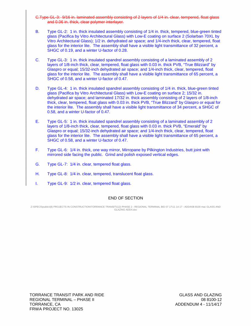
C.Type GL-3: 9/16 in. laminated assembly consisting of 2 layers of 1/4 in. clear, tempered, float glass and 0.06 in. thick, clear polymer interlayer.
B. Type GL-2: 1 in. thick insulated assembly consisting of 1/4 in. thick, tempered, blue-green tinted glass (Pacifica by Vitro Architectural Glass) with Low-E coating on surface 2 (Solarban 70XL by Vitro Architectural Glass); 1/2 in. dehydrated air space; and 1/4-inch thick, clear, tempered, float glass for the interior lite. The assembly shall have a visible light transmittance of 32 percent, a SHGC of 0.19, and a winter U-factor of 0.28.
C. Type GL-3: 1 in. thick insulated spandrel assembly consisting of a laminated assembly of 2 layers of 1/8-inch thick, clear, tempered, float glass with 0.03 in. thick PVB, “True Blizzard” by Glaspro or equal; 15/32-inch dehydrated air space; and 1/4-inch thick, clear, tempered, float glass for the interior lite. The assembly shall have a visible light transmittance of 65 percent, a SHGC of 0.58, and a winter U-factor of 0.47.
D. Type GL-4: 1 in. thick insulated spandrel assembly consisting of 1/4 in. thick, blue-green tinted glass (Pacifica by Vitro Architectural Glass) with Low-E coating on surface 2; 15/32 in. dehydrated air space; and laminated 17/32 in. thick assembly consisting of 2 layers of 1/8-inch thick, clear, tempered, float glass with 0.03 in. thick PVB, “True Blizzard” by Glaspro or equal for the interior lite. The assembly shall have a visible light transmittance of 34 percent, a SHGC of 0.58, and a winter U-factor of 0.47.
E. Type GL-5: 1 in. thick insulated spandrel assembly consisting of a laminated assembly of 2 layers of 1/8-inch thick, clear, tempered, float glass with 0.03 in. thick PVB, “Emerald” by Glaspro or equal; 15/32-inch dehydrated air space; and 1/4-inch thick, clear, tempered, float glass for the interior lite. The assembly shall have a visible light transmittance of 65 percent, a SHGC of 0.58, and a winter U-factor of 0.47.
F. Type GL-6: 1/4 in. thick, one way mirror, Mirropane by Pilkington Industries, butt joint with mirrored side facing the public. Grind and polish exposed vertical edges.
G. Type GL-7: 1/4 in. clear, tempered float glass.
H. Type GL-8: 1/4 in. clear, tempered, translucent float glass.
I. Type GL-9: 1/2 in. clear, tempered float glass.
END OF SECTION
Z:\SPECS\public\(8) PROJECTS IN CONSTRUCTION\TORRANCE TRANSIT\(12) PHASE 2 - REGIONAL TERMINAL BID 07 17\11 14 17 - ADD4\08 8100 mac GLASS AND GLAZING ADD4.doc