b t1 11-45 qualcomm lattice mipi vgi for sideband gpio · • mipi vgi rev-1 (3-wire) max speed:...
TRANSCRIPT

Lalan Mishra Satwant SinghPrincipal Engineer Sr. Director Qualcomm Technologies, Inc. Lattice Semiconductor
MIPIVGISMforSidebandGPIOandMessagingConsolidationonMobileSystem

©2017MIPIAlliance,Inc.
Agenda• TheProblemStatement• VirtualGPIOInterface(MIPIVGISM):Concept• MIPIVGISM Architecture• ApplicationScenarios• Summary• Q&A
2

©2017MIPIAlliance,Inc.
MobileConnectivityExpansionTrends
3
Cellularq 2G/3G/4G è LTE-Advanced è 5G
WiFi
q 802.11a/b/g/n/ac èax 802.11ad/WiGig
Video
q VGA/SD/HD è 4K è 8K
Docking
q Charging/audio/video èProductivity, Games and External Storage
Mobile Influencedq Drones, IoT, Automotive, ….q CAT-1 to CAT-3 Low-Power LTE
Modem Support

©2017MIPIAlliance,Inc.
TheProblemofSidebandProliferation
4
ApplicationsProcessor(SoC)
Modem WirelessLANBluetooth
GigabitWirelessLAN(60-GHz)
GPIOs:x9
CLKR
EQ
WAK
EUP
RESET
EN
PCIe/M
-PCIe/
HSIC/U
SB
CLKR
EQWAK
EUP
RESET
CLKR
EQ
WAK
EUP
RESET
EN
STAT
US
ERR
CHNL_RD
Y
P_DN
P_DNGPIOs:
x5GPIOs:x5
Companion/Bridge-Chip
CLKR
EQ
WAK
EUP
RESET
EN
P_ON
INT1
INT2
INT3
GPIOs:x8
O/P
O/P
O/P I/P
O/P
O/P
O/P I/P
I/P
I/P
I/P
I/P
I/P
I/P
PWR_
ON
VOL_UP
VOL_DN
HOME
BACK
LOCK
MUTE
LID
GPIOs:x8
CHG_
LED_
R
CHG_
LED_
G
CHG_
LED_
B
WiFi_ON
BT_O
N
MEM
_ACC
ESS
GPIOs:x6
Ethernet
PCIe/M
-PCIe/
HSIC/U
SB
PCIe/M
-PCIe/
HSIC/U
SB
PCIe/M
-PCIe/
HSIC/U
SB
OptionalConnector

©2017MIPIAlliance,Inc.
TheProblemofSidebandProliferation
5
Domain NumberofSideband I/O
Camera/Imaging 6to12
AudioCODEC 4to7
CellularModem 3to10
WirelessLANModem 3to10
Bridge Chip 3to8
SensorHub 4to18
TypicalSidebandUtilization
TypicalSidebandGPIOs:23to65

©2017MIPIAlliance,Inc.
MIPIVGISM:SolutiontoSidebandProliferation
6
ApplicationsProcessor(SoC)
WWAN WiFi/BT 60-GHz
SDIO/H
SIC/USB
/PC
Ie
SDIO/H
SIC/USB
/PC
Ie
I/OLinesx2
High-SpeedHub
O/P
O/P
O/P I/P
O/P
O/P
O/P I/P
I/P
I/P
I/P
I/P
I/P
I/P
PWR_
ON
VOL_UP
VOL_DN
HOME
BACK
LOCK
MUTE
LID
CHG_
LED_
R
CHG_
LED_
G
CHG_
LED_
B
WiFi_ON
BT_O
N
MEM
_ACC
ESS
Ethernet
MIPIVGII/OExpander
I/OLinesx2
I/OLinesx2
I/OLinesx2
MIPIV
GI
I/OLinesx2
Modem
ApplicationsProcessor(SoC)
Modem WirelessLANBluetooth
GigabitWirelessLAN(60-GHz)
PCIe/M
-PCIe/
HSIC/U
SB
Companion/Bridge-ChipPC
Ie/M
-PCIe/
HSIC/U
SB
PCIe/M
-PCIe/
HSIC/U
SB
PCIe/M
-PCIe/
HSIC/U
SB
OptionalConnector
MIPIV
GI
MIPIV
GI
MIPI
VGI
MIPI
VGI

©2017MIPIAlliance,Inc.
MIPIVGISM:TheConcept
7
• MIPIVGI consolidatesN-sidebandGPIOsandsub-100MHzserialmessagingover2or3 wireinterfaceinaPoint-to-Pointconfiguration
• 2-wireMIPIVGI:Asynchronous,Full-Duplex(4-Mbpsmax.)
• 3-wireMIPIVGI:Synchronous,Full-Duplex
• MIPIVGIRev-1(3-wire)MaxSpeed:76.8MHz
SBGP
IOs
Txà Rx
Virtual GPIO Interface(MIPI VGI)
ü Consolidates Low Speed Messaging Interface and and Sideband GPIOs (N-pins to 2/3-pins reduction)
LSMsg
SBGP
IOs
MIPIVGI
MIPIVGI
Dev-1
Rxß Tx
Clock(Opt.)
NSidebandGPIOs
Dev-2
Dev-1 Dev-2

©2017MIPIAlliance,Inc.
LimitationofConventionalTechniques
ü HLOSprocessinglatencyvarieswidelyü Deep-sleeptoactive-statetypicallatency:Typicallyà 30to100-mSü TiminguncertaintynotsuitableforthekeyIPCside-bandsignaling
SoCInternalBusSoC
CoreProcessor
C2CComm.IPBlock
LowPowerModeSystemManager
ClockGenerator
LP-DDR
2
1
3
4
5
6IPCside-bandBusSub-System
SoC
e.g.,I2C,UART,SPI
8

©2017MIPIAlliance,Inc.
MIPIVGISMArchitecturalBlock-Diagram
9

©2017MIPIAlliance,Inc.
MIPIVGISM PhysicalInterface:2-wireor3-wire
MIPIVGIDevice#
1
MIPIVGIDevice#
2
Txà Rx
Rxß Tx
CLK
1
2
Asynchronous MIPI VGIq Initial and Power State Transition mode communication over 2-wire, 4-Mbps max.
1
2 Synchronous MIPI VGIq Common clock (Up to 76.8 MHz in VGI Rev-1)q Sleep clock based operation supported in Low Power Modes
10

©2017MIPIAlliance,Inc.
MIPIVGISM TechniquesAt-a-Glance
11

©2017MIPIAlliance,Inc.
MIPIVGISM Roadmap# VGIFeatures VGIv1.0 VGINext
1 2-wireand3-wireI/Fsupport ü ü
2 Default PWMencoding ü ü
3 UARTEncoding ü ü
4 PM-PWMEncoding(Phase-ModulatedPWM) - ü
5 2-wiremodemaxthroughput 4Mbps 8Mbps(PM-PWM)
6 3-wiremodemaxthroughput 76.8Mbps 153.6Mbps
7 1.2V,1.8V Operationsupport ü ü
8 1-wiremodesupport - ü
12

©2017MIPIAlliance,Inc.
MIPIVGISM Init SequencePONReset
• HostVGImodulegetsinitializedwiththepresetnumberofGPIOs.
• Host’sTxo/plevelissettoLOW• Host’sRxisreadyforinputlevelread-Input=LOW=>Slavenotready-Input=HIGH=>Slaveready
IsSlaveVGIready?
• Hostsendsenumeration-initiationpacket• Slaveresponds
FurtherCommunicationasneeded
Fromthispointonwards
No
Yes
13

©2017MIPIAlliance,Inc.
Synchronous3-WireMIPIVGISM
14

©2017MIPIAlliance,Inc.
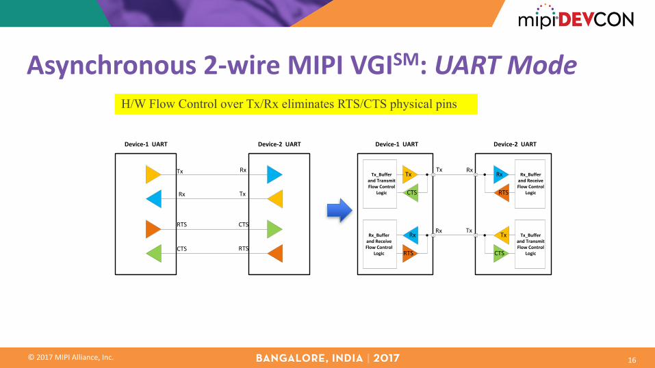
Asynchronous2-wireMIPIVGISM:UARTMode
D0
Start-BitIntermediate
Stop-Bit Stop-Bit
D1 D2 D3 D4 D5 D6 D7
Illustration#1:8-bitframe
D0 D1 D2 D3 D4 D5 D6 D7 D0 D1 D2 D3
Illustration#2:12-bitframe
D0 D1 D2 D3 D4 D5 D6 D7 D0 D1 D2 D3
Illustration#2:16-bitframe
D0 D1 D2 D3
15
©2017MIPIAlliance,Inc.
Asynchronous2-wireMIPIVGISM:UARTModeH/W Flow Control over Tx/Rx eliminates RTS/CTS physical pins
Tx Rx
TxRx
RTS CTS
CTS RTS
Device-1UART Device-2UART
Tx Rx
TxRx
Tx_BufferandTransmitFlowControl
Logic
Rx_BufferandReceiveFlowControl
Logic
Tx_BufferandTransmitFlowControl
Logic
Rx_BufferandReceiveFlowControl
Logic
Device-1UART
Tx
TxRx
Rx
CTS
CTSRTS
RTS
Device-2UART
16

©2017MIPIAlliance,Inc.
AsynchronousMIPIVGISM:Phase-ModulatedPWM
17

©2017MIPIAlliance,Inc.
MIPIVGISM ProtocolStart-bit
0Fn_Bit-0 Fn_Bit-1
GPIO/MsgBit-0
GPIO/MsgBit-1
GPIO/MsgBit-2
GPIO/MsgBit-(n-1)
GPIO/MsgBit-n
Stop-bit1
…………..
Stream-LnBit-(n-1)
Type_Bit(vGPIO/Msg)
Stream-LnBit-0
Stream-LnBit-1
Stream-LnBit-n…………..
FollowingbitsarevGPIOstates0
1 Followingbitsaremessagebits.0
0 Followingbit-streamrepresentthevGPIOstreamlengthtobesetonthereceiverside.1
1 Followingbit-streamrepresentthenewvGPIOstreamlengthacknowledgementw.r.tthepreviouslyreceivedstream-lengthprogrammingcommand.1
0
Function_Bits Description
NOTE:Themechanismhasafixedoverheadoftwo-bitsoverthebase-linevGPIOimplementation.
Type_Bit1=>vGPIO0=>Msg
18

©2017MIPIAlliance,Inc.
MIPIVGISM FSMIntegrationwithMIPII3CSM
Host(Master)SoC
Camera#1
Camera#2
Sensor#1
TouchScreen
Controller
Peripheral#n
I3CBusI3C
AdditionalSidebandSignals
GPIOI/P
GPIOO/P
1
Data
CLK
Standby
Reset 24
5
1
2
3
3Flash
Standby 16
7 2Reset
Enable 18
9 2Reset
Enable 110
11 2Reset
Enable 112
13 2Reset
Wakeup 314
Periph-Adrs:0x01
Periph-Adrs:0x02
Periph-Adrs:0x03
Periph-Adrs:0x04
Periph-Adrs:0xn
• VGIFSMcouldbeintegratedwithaserialinterfaceofchoice,suchasMIPII3C(SM)
• I3C(SM)supportsMIPIVGIintegrationthroughdedicatedCommonCommandcodes(CCC)supportinI3C(SM) v1.0
• HelpsreduceHardwareeventpinsatsystemlevel
19

©2017MIPIAlliance,Inc.
MIPIVGISM FSMIntegrationwithMIPII3CSM
HostSoC
Peripheral#1
Peripheral#2
Peripheral#3
Peripheral#(n-1)
Peripheral#n
I3CBusI3CIP
VGI
VGI
VGI
VGI
VGI
VGI
I3C
I3C
I3C
I3C
I3C
Data
CLK• HWEventsideband
signalsareeliminated
• VGI-FSM(FiniteStateMachine)performsI3C(SM) messageencoding/decodingforHWeventsandthusfreesuptheassociatedCPUonthehost-SoCforthesetasks.
• ImpactisreducedLatencyandPowerconsumption.
20

©2017MIPIAlliance,Inc.
ComparingMIPIVGISM
StandardizedControlMethods
SymmetricControl
VariableClocking
VGI
UART
SPI
RFFE
I3C
ReferenceClock
Point-to-MultiPoint
Open-Drain/RCDependent
• SPI– Master-Slaveapproach– Customimplementations,nocommonmethods
• MIPII3C(SM)
– Multi-MasterMulti-Slave,Open-Drainapproach– In-bandinterrupts
• MIPIRFFE(SM)
– Master-MultiMulti-Slaveapproach
• UART– Customimplementations,requiresreferenceclocks
• MIPIVGI(SM)
– Symmetriccontrolapproach(NoMasterNoSlave)– Initializationfromeitherside
21

©2017MIPIAlliance,Inc.
ComparingMIPIVGISM - Clocking• UART
– RequiresReferenceClockwithAgreedrates• SPI,MIPII3C(SM),MIPIRFFE(SM)
– ClockisforwardedfromMastertoSlave• MIPIVGI(SM)
– UsingRO-PWMPHYoption,theclockingisforwardedwithdata
– OnlyTransmitterrequiresclocktocreatetelegrams
– Receivercapturestelegramswithoutinternalclock• Usefulfordeviceswhichpowerdown• Usefulforverysimplewrite-onlydevices(LED
bank)
StandardizedControlMethods
SymmetricControl
VariableClocking
VGI
UART
SPI
RFFE
I3C
ReferenceClock
Point-to-MultiPoint
Open-Drain/RCDependent
22

©2017MIPIAlliance,Inc.
PhasedMIPIVGISM Adoption– LeveragingSmallerFPGAs
DeviceA(e.g.,Host)
DeviceB(e.g.,
Peripheral)VGI
þVGI-ReadyþVGI-Ready
DeviceA DeviceB
þVGI-Ready ýVGI-Ready
SmallFPGAVGI
DeviceA DeviceB
ýVGI-Ready
SmallFPGA
ýVGI-Ready
SmallFPGAVGI
FPGAVGIBridging:Case-3
FPGAVGIBridging:Case-1
FPGAVGIBridging:Case-2
NativeVGIInterface
þFullVGIAdoption PartialVGIAdoption
PartialVGIAdoption NoVGIAdoption
þVGI-ReadyýVGI-Ready
DeviceA DeviceBSmallFPGA VGISB/
GPIOsSB/GPIOs
SB/GPIOs
Acrossconnectors,cables,hingesorpogo-pinsetc.
SB/GPIOs
SB:SidebandSignals
Sideband(SB)/GPIOs+Messaging
23
©2017MIPIAlliance,Inc.
Summaryq SidebandGPIOsaddtoSoC andPCBlevelcostandcomplexity
q MIPIVGIconsolidatessidebandGPIOsandLow-SpeedserialmessaginginterfaceinP2PconfigurationtoreduceI/Opins
q Both2and3-wireinterfaceoptionsareavailable
q CommonPWMstart-upmodeensuresinteroperability
q TheVGIFSMcanbecombinedwithanyotherinterfacebusofchoice,e.g.I3C(SM)VGI
q TheMIPIVGISpecificationistobereleasedin2018
24

