b , s usa titus
TRANSCRIPT

2004 PRODUCT BROCHURE, SEPTEMBER 2004 PRINTED IN USACOPYRIGHT © 2004 BY AIR SYSTEM COMPONENTS LP.
ALL RIGHTS RESERVED. NO PART OF THIS CATALOG MAY BEREPRODUCED OR TRANSMITTED IN ANY FORM OR BY ANY MEANS,ELECTRONIC OR MECHANICAL, INCLUDING PHOTOCOPYING ANDRECORDING, OR BY ANY INFORMATION STORAGE AND RETRIEVAL
SYSTEM WITHOUT PERMISSION IN WRITING FROM AIR SYSTEMCOMPONENTS LP.
PRODUCT IMPROVEMENT IS A CONTINUING ENDEAVOR AT TITUS.THEREFORE, PRODUCT DESCRIPTIONS ARE SUBJECT TO CHANGEWITHOUT NOTICE. CONTACT YOUR TITUS REPRESENTATIVE TO
VERIFY DETAILS.
T a b l e o f C o n t e n t s 3
Flyer . . . . . . . . . . . . . . . . . . . . . . . . . . . . . . . . . . . . . . . . . . . . . . . . . . . . . . . . . . . . . . . . . . . . . .4Introduction . . . . . . . . . . . . . . . . . . . . . . . . . . . . . . . . . . . . . . . . . . . . . . . . . . . . . . . . . . . . . . .6TITAN ECM Programming Process . . . . . . . . . . . . . . . . . . . . . . . . . . . . . . . . . . . . . . . . . .9TFS Series Fan Terminal
Description . . . . . . . . . . . . . . . . . . . . . . . . . . . . . . . . . . . . . . . . . . . . . . . . . . . . . . . . . . . . . . . . . . . . . . . .10Dimensions - H20, Electric Heat, Accessories, FLA . . . . . . . . . . . . . . . . . . . . . . . . . . . . . . . . . . . .11Fan Curves . . . . . . . . . . . . . . . . . . . . . . . . . . . . . . . . . . . . . . . . . . . . . . . . . . . . . . . . . . . . . . . . . . . . . . . .12H20 Performance Data . . . . . . . . . . . . . . . . . . . . . . . . . . . . . . . . . . . . . . . . . . . . . . . . . . . . . . . . . . . . .13Radiated Sound NC . . . . . . . . . . . . . . . . . . . . . . . . . . . . . . . . . . . . . . . . . . . . . . . . . . . . . . . . . . . . . . . .14Discharge Sound NC . . . . . . . . . . . . . . . . . . . . . . . . . . . . . . . . . . . . . . . . . . . . . . . . . . . . . . . . . . . . . . .15Radiated Sound Power, ARI Certification Points . . . . . . . . . . . . . . . . . . . . . . . . . . . . . . . . . . . . . .16Discharge Sound Power, ARI Certification Points . . . . . . . . . . . . . . . . . . . . . . . . . . . . . . . . . . . . .17TFS with ECM motor Fan Curves . . . . . . . . . . . . . . . . . . . . . . . . . . . . . . . . . . . . . . . . . . . . . . . . . . .18TFS with ECM Radiated Sound NC . . . . . . . . . . . . . . . . . . . . . . . . . . . . . . . . . . . . . . . . . . . . . . . . .19TFS with ECM Discharge Sound NC . . . . . . . . . . . . . . . . . . . . . . . . . . . . . . . . . . . . . . . . . . . . . . . .20TFS with ECM Radiated Sound Power . . . . . . . . . . . . . . . . . . . . . . . . . . . . . . . . . . . . . . . . . . . . . . .21TFS with ECM Discharge Sound Power . . . . . . . . . . . . . . . . . . . . . . . . . . . . . . . . . . . . . . . . . . . . . .22
TFS-F, Fantom IQ, Series Fan Terminal
Description . . . . . . . . . . . . . . . . . . . . . . . . . . . . . . . . . . . . . . . . . . . . . . . . . . . . . . . . . . . . . . . . . . . . . . . .23Dimensions - H20, Electric Heat, Accessories, FLA . . . . . . . . . . . . . . . . . . . . . . . . . . . . . . . . . . . .24Fan Curves . . . . . . . . . . . . . . . . . . . . . . . . . . . . . . . . . . . . . . . . . . . . . . . . . . . . . . . . . . . . . . . . . . . . . . . .25H20 Performance Data . . . . . . . . . . . . . . . . . . . . . . . . . . . . . . . . . . . . . . . . . . . . . . . . . . . . . . . . . . . . .26Radiated Sound NC . . . . . . . . . . . . . . . . . . . . . . . . . . . . . . . . . . . . . . . . . . . . . . . . . . . . . . . . . . . . . . . .27Discharge Sound NC . . . . . . . . . . . . . . . . . . . . . . . . . . . . . . . . . . . . . . . . . . . . . . . . . . . . . . . . . . . . . . .28Radiated Sound Power, ARI Certification Points . . . . . . . . . . . . . . . . . . . . . . . . . . . . . . . . . . . . . .29Discharge Sound Power, ARI Certification Points . . . . . . . . . . . . . . . . . . . . . . . . . . . . . . . . . . . . .20TFS-F with ECM motor Fan Curves . . . . . . . . . . . . . . . . . . . . . . . . . . . . . . . . . . . . . . . . . . . . . . . . .31TFS-F with ECM Radiated Sound NC . . . . . . . . . . . . . . . . . . . . . . . . . . . . . . . . . . . . . . . . . . . . . . . .32TFS-F with ECM Discharge Sound NC . . . . . . . . . . . . . . . . . . . . . . . . . . . . . . . . . . . . . . . . . . . . . . .33TFS-F with ECM Radiated Sound Power . . . . . . . . . . . . . . . . . . . . . . . . . . . . . . . . . . . . . . . . . . . . .34TFS-F with ECM Discharge Sound Power . . . . . . . . . . . . . . . . . . . . . . . . . . . . . . . . . . . . . . . . . . . .35
Suggested Specifications TFS, TFS-F . . . . . . . . . . . . . . . . . . . . . . . . . . . . . . . . . . . . . . . .36
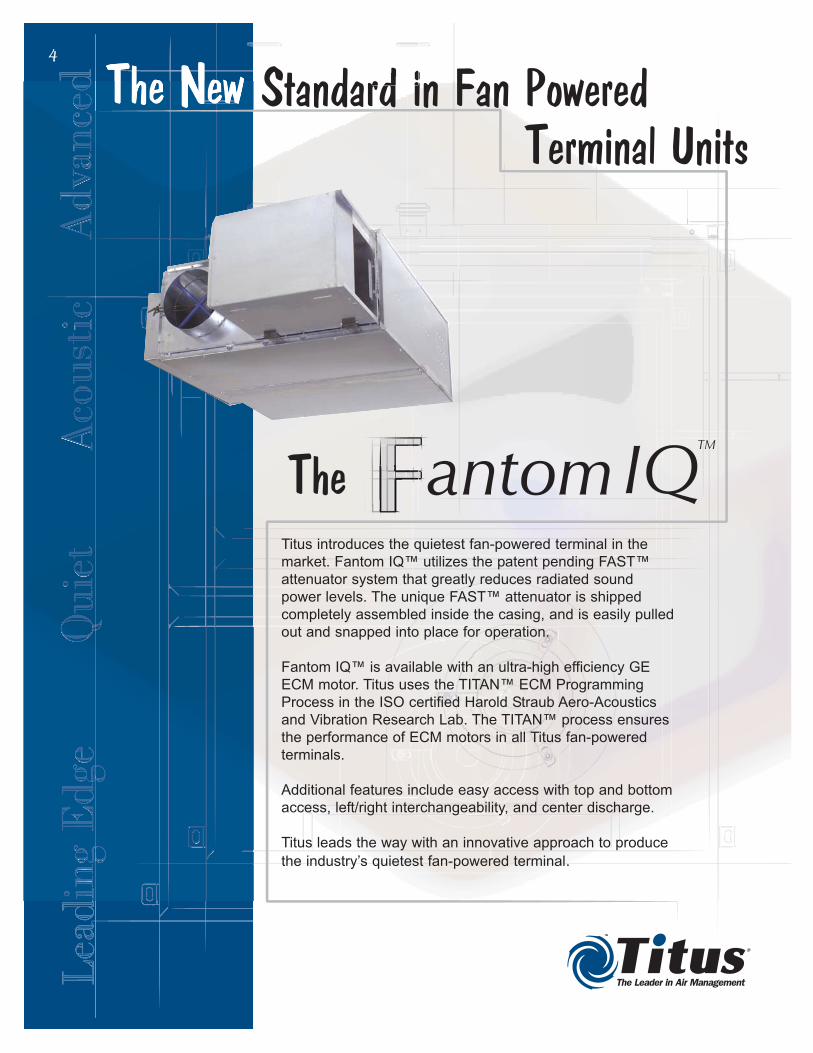
Titus introduces the quietest fan-powered terminal in the
market. Fantom IQ™ utilizes the patent pending FAST™
attenuator system that greatly reduces radiated sound
power levels. The unique FAST™ attenuator is shipped
completely assembled inside the casing, and is easily pulled
out and snapped into place for operation.
Fantom IQ™ is available with an ultra-high efficiency GE
ECM motor. Titus uses the TITAN™ ECM Programming
Process in the ISO certified Harold Straub Aero-Acoustics
and Vibration Research Lab. The TITAN™ process ensures
the performance of ECM motors in all Titus fan-powered
terminals.
Additional features include easy access with top and bottom
access, left/right interchangeability, and center discharge.
Titus leads the way with an innovative approach to produce
the industry’s quietest fan-powered terminal.
4

5
Changing MarketTitus designed the new TFS series fan powered
terminal using a base box plus options concept
borrowed from the automotive industry. The TFS base
box is cost competitive with other manufacturers' non-
quiet fan powered terminals. The TFS can be
upgraded to a TFS-F by adding the Fantom™
Intelligently Quiet™ (Fantom IQ™) acoustic upgrade
package. The TFS-F Fantom IQ is the quietest fan box
in the industry!
Development ProcessExtensive research was done to look at all areas of
the box design. Titus investigated and tested
technologies related to motor development, motor
mounting, motor positioning, acoustic materials,
cabinet design, blower technology, and alternate liner
options. Many of these technologies have been
incorporated into the TFS and TFS-F Fantom IQ
design.
FlexibilityThe TFS and TFS-F Fantom IQ series fan powered
terminals provide the flexibility to be cost competitive
when sound is not an issue and extremely quiet when
sound is an issue. The TFS and TFS-F Fantom IQ can
be mixed on projects to get the best combination of
quiet units and cost effective units to meet the needs
of the project.
TITAN ECM Programming ProcessThe TFS and TFS-F Fantom IQ are available with the
optional ultra high efficiency GE ECM motor. Any
manufacturer can purchase the ECM motor. The
difference is in the development and programming of
the ECM motor to operate effectively and efficiency
within the specific fan powered terminal's design and
configuration. The ECM motor only offers a benefit, if it
is developed and programmed correctly within the
specific fan box.
Titus uses the Titus Iterative Test & Analysis
Network™ (TITAN™) ECM Programming Process in
its ISO 9001:2000 certified lab, the Harold Straub
Research & Training Center. The TITAN process
ensures the performance of the ECM motor in all of
the Titus fan-powered terminals.
Features
Optional Upgrades
Features Benefits
Access doors • Easier both top and
bottom access to the
motor and damper sections.
• Improved flanged design
means fewer screws and
easier removal.
Center Discharge • Same location between right
and left hand units.
• Better shipping protection of
water coils.
Interchangable
motor/blower
• Easy size changes
when necessary in the field.
Interchangable inlets • Easily change inlet sizes in
the field.
Shaft down motor • Reduces shaft loading and
increases motor reliability.
• Shaft down position eliminates
the need for fan packing,
which eliminates the possibility
of the motor being started with
fan packing in place.
• Lower profile casing.
• Shaft down positions
provides vibro-acoustic
benefits.
Easy to install
motor/blower
assembly
• Tabbed brackets allow
motor/blower assembly to "hang"
in place to allow for quick
alignment of screw holes for
easy field installation.
Upgrade Benefits
FAST acoustic
upgrade system
• Allows the base and quiet boxes
to be mixed and matched on a
project.
• Adding FAST attenuators make
the TFS Fantom IQ the quietest
fan box in the market.
TITAN
programmed ECM
motor
• Energy efficient operation.
• Pressure independent
operation.
• Uses Titus Iterative Test &
Analysis Network (TITANTM).
Please visit http://www.titus-hvac.com or contact your local Titus representative for
additional information.

I n t r o d u c t i o n6
AeroCross multipoint
center averaging flow
sensor provides
excellent flow control.
The integral patent pending FASTTM attenuator
system, has a telescoping external attenuator
that is shipped internal to the unit to provide
secure shipping and is easily pulled into place
when installed.
The internal section of the
FASTTM attenuator system
reduces primary air
generated radiated sound. Shaft down, vertical mount
motor arrangement provides
even weight distribution on
the motor mounting system
and reduced acoustic
characteristics.
7
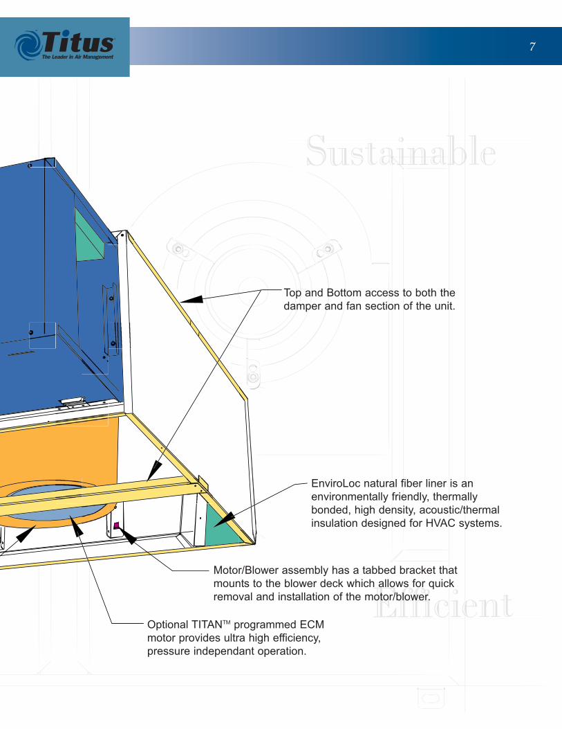
Top and Bottom access to both the
damper and fan section of the unit.
Optional TITANTM programmed ECM
motor provides ultra high efficiency,
pressure independant operation.
Motor/Blower assembly has a tabbed bracket that
mounts to the blower deck which allows for quick
removal and installation of the motor/blower.
EnviroLoc natural fiber liner is an
environmentally friendly, thermally
bonded, high density, acoustic/thermal
insulation designed for HVAC systems.
8
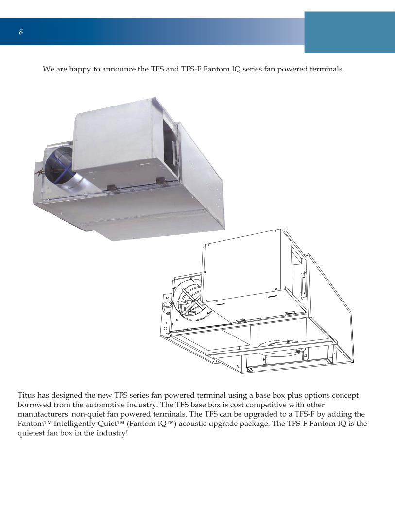
Titus has designed the new TFS series fan powered terminal using a base box plus options conceptborrowed from the automotive industry. The TFS base box is cost competitive with othermanufacturers' non-quiet fan powered terminals. The TFS can be upgraded to a TFS-F by adding theFantom™ Intelligently Quiet™ (Fantom IQ™) acoustic upgrade package. The TFS-F Fantom IQ is thequietest fan box in the industry!
We are happy to announce the TFS and TFS-F Fantom IQ series fan powered terminals.

T I T A N E C M P r o g r a m m i n g P r o c e s s 9
TITAN ECM Programming Process
The TFS and TFS-F Fantom IQ are available withthe optional ultra high efficiency GE ECM motor.Any manufacturer can purchase the ECM motor.The difference is in the development andprogramming of the ECM motor to operateeffectively and efficiency within the specific fanpowered terminal's design and configuration. TheECM motor only offers a benefit if it is developedand programmed correctly within the specific fanbox.
Titus uses the Titus Iterative Test & AnalysisNetwork™ (TITAN™) ECM ProgrammingProcess in its ISO 9001:2000 certified lab, theHarold Straub Research & Training Center. TheTITAN process ensures the performance of theECM motor in all of the Titus fan poweredterminals.
History of ECM Motors in Commercial HVAC
Titus has been programming ECM motors foralmost a decade. In early 1995, GE and Titusworked together to bring their ECM motors intothe commercial HVAC market.
Understanding that the ECM motor was asignificant first cost increase over standard PSCmotors, Titus retrofitted one floor of an officebuilding in Dallas, TX with ECM motors andcompared the energy usage of that floor against afloor with PSC motors over an eighteen monthperiod to prove the energy savings would providean acceptable payback of three years or less.
Titus shipped the first ECM fan powered terminalto a school district in Houston in 1997. Titus hasbeen shipping ECM motors ever since. Thisextensive history and commitment to thedevelopment of the ECM motor for commercialapplications, makes Titus an expert in ECMdevelopment. This expertise is the basis of theTITAN ECM Programming Process.
Process Summary
The TITAN ECM Programming Process is aniterative process of developing constants for theECM motor to operate at the optimum efficiencyand provide pressure independent airflow. Up to adozen test runs are preformed using the GE ECMmotor programming interface equipment toensure the correct motor constants. Developing thecorrect motor constants allows optimal control ofthe speed and torque of the motor in the particularfan box design.
The minimum and maximum fan curves aredetermined based on minimum and maximumrpm of the ECM motor (300 rpm and 1200 rpmrespectively). The GE interface unit plots rpm vs.torque of the motor and determines the differencebetween measured venturi CFM and the ECMcalculated CFM. This test is repeated until thedifference in venturi CFM and the ECM calculatedCFM equals zero. Once the CFM difference is zero,or as close to zero as possible, the ECM constantsare saved for that unit's airflow characteristics.
All Titus fan powered terminals with ECM motorsare provides with a factory installed PWMcontroller. The PWM voltage signal is calibrated toprovide 100% fan at full voltage (10.0V) andminimum fan at minimum voltage (1.0V). Thecalibrated PWM allows the ECM motor tooperated as programmed by Titus regardless ofwhat manufacturer's DDC controller provides thevoltage signal to the PWM controller. This ensuresthe pressure independent operation of the motorwith any DDC controller. The PWM signal canalso be controlled manually using a dial pot muchlike a SCR on a standard PSC motor.
The TITAN ECM Programming Process extendsfrom the lab to the ISO 9001:2000 certified factorieswhere individual ECM motors are programmedwith the appropriate ECM program for each order.

TTFFSS
1100 TTFFSS •• DDeessccrriippttiioonn
Performance DataPTFS . . . . . . . . . . . . . .10ATFS . . . . . . . . . . . . . .10DTFS . . . . . . . . . . . . . .10
SpecificationsPTFS . . . . . . . . . . . . . .35ATFS . . . . . . . . . . . . . .35DTFS . . . . . . . . . . . . . .35
Primary Air Inlet with AeroCross Multipoint
Center Averaging Sensor
Induced Air Inlet
A
C
E
B 338 N 20
614
12
F
G
J
H
K
L
W
D
• Two casings for easy design layout.
• Pressure independent primaryairflow control.
• AeroCrossTM multi-point inletvelocity sensor with centeraveraging.
• Energy-efficient fan motor,permanent split capacitor type,mounted with vibration isolators.
• Optional TITANTM programmedECM motor provides ultra-highefficiency, pressure independentoperation.
• Adjustable SCR fan speedcontrol with minimum voltagestop.
• Single point electrical, pneumaticmain, and thermostatconnections.
• EnviroLoc, natural fiberinsulation, covered to prevent airerosion, meets requirements ofNFPA 90A and UL 181.
• 20-gauge galvanized steelcasing.
• Rectangular discharge opening isdesigned for flanged ductconnections.
• Centered, rectangular dischargeopening is designed for flangedduct connections.
• Top and bottom access panelscan be removed for service.
Fan PoweredSeries Type
Quiet OperationModels:
PTFS• Pneumatic Control
ATFS• Analog Control
DTFS• Digital Control
TFS: Sizes B-E
Size Unit A B C D E F G H J K L N W Filter Size
6 6 5 7/8 2 7/8
8 6 7 7/8 2 7/8
10 7 9 7/8 4 7/8
12 8 11 7/8 4 7/8
6 6 5 7/8 2 7/8
8 6 7 7/8 2 7/8
10 7 9 7/8 4 7/8
12 8 11 7/8 4 7/8
10 7 9 7/8 4 7/8
12 8 11 7/8 4 7/8
14 10 13 7/8 6 7/8
16 11 15 7/8 6 7/8
12 8 11 7/8 4 7/8
14 10 13 7/8 6 7/8
16 11 15 7/8 6 7/8
D
E
11 1/8 2 1/4
B
C
8 11 7/8 15 7/8 16 1/2
42 37 16 x 14
Model TFS Series Unit
8 13 7/8 11 7/8 14 1/8 11 1/2 16
46 3/4 39 14 x 1811 1/8 20 14 5/8 2

TTFFSS
1111TTFFSS •• DDiimmeennssiioonnss
S
R
M
1"
9
Heater Rack Access Cover
934 S T
U
R
1" Typ.
1231
614
Hot Water Coil Section
Standard Features
• 1/2-inch copper tubes.
• Aluminum ripple fins.
• Connections: Male solder. 5/8-inch for both 1- and 2-row.Left or right handconnections.
• Galvanized steel casing.
• Flanged duct connection.
• Coil is installed at dischargeof unit.
Coil Rows
• 1-Row
• 2-Row
Supply Voltage
• 120V, 1 ph, 60 Hz.
• 208/240V, 1 ph, 60 Hz.
• 277V, 1 ph, 60 Hz.
Electric Coil Section
Standard Features
• Automatic reset thermalcutouts, one per element.
• Single point electrical connection for entire unit, including coil.
• Positive pressure air flowswitch.
• Flanged duct connection.
• Coil is installed atdischarge of unit.
• Preset P/E switches withpneumatic units.
• 80/20 nickel chromeelement wire
• Transformers (analog anddigital models only)
Unit Size M (1-Row) M (2-Row) R S
B, C 1 1 20 1/2 12 1/2
D, E 1 1 1/4 25 17 1/2
Hot Water Coil Section (Discharge Mounted)
Unit Size U R S T
B, C 11 3/8 14 1/2 11 1/2 2 3/8
D, E 11 17 15 3 1/8
Electric Coil Section (Discharge Mounted)
B 1/6 2.3 0.9 0.8
C 1/4 4 1.8 1.4
D 1/3 8.5 3.6 3
E 3/4 8.6 4.2 4.5
Unit
Size
Motor
hp
277/1/60
FLA
120/1/60
FLA
208/240/1/60
FLA
Electrical Data
FLA = Full Load Amperage, as tested in accordance with UL 1995.
All fan motors are single phase, same voltage as electric coil (whensupplied), with exception that 277V motors are used with 480V, 3phase coils (4 wire wye).
Additional Accessories (Optional)
• Induced air filter, 1-inch thick disposable
construction type.
• Fan disconnect switch (not available on
units with optional electric coils).
• 1-inch Liner.
• EnviroLoc Liner.
• Fibre-Free Liner.
• SteriLoc Liner.
• Fan unit fusing.
• Hanger brackets.
• Camlocks on fan access door.
Note: R and S are inside dimensions.
Options
• Mercury contactors.
• Fuse block.
• Disconnect switch,door interlock type.
• Manual resetcutout.
• Dust tightconstruction.
Supply Voltage
• 208V, 1 ph, 60 Hz.
• 240V, 1 ph, 60 Hz.
• 277V, 1 ph, 60 Hz.
• 208V, 3 ph, 60 Hz.
• 480V, 3 ph, 60 Hz. (4 wire wye only)

TTFFSS
1122 TTFFSS •• PPeerrffoorrmmaannccee DDaattaa
TFS Size C
300
400
500
600
700
800
900
1000
1100
1200
1300
0 0.1 0.2 0.3 0.4 0.5 0.6
Dow nstream Static Pressure
(Inches of Water)
CFM
TFS Size B
150
200
250
300
350
400
450
500
550
600
650
700
0 0.1 0.2 0.3 0.4 0.5 0.6
Dow nstream Static Pressure
(Inches of Water)
CFM
TFS Size D
700
800
900
1000
1100
1200
1300
1400
1500
1600
1700
1800
1900
2000
0 0.1 0.2 0.3 0.4 0.5 0.6
Dow nstream Static Pressure
(Inches of Water)
CFM
TFS Size E
1300
1400
1500
1600
1700
1800
1900
2000
2100
2200
2300
2400
2500
2600
2700
0 0.1 0.2 0.3 0.4 0.5 0.6
Dow nstream Static Pressure
(Inches of Water)
CFM
Models: PTFS, ATFS, DTFS • Airflow vs. Downstream Static Pressure
Primary Air Inlet Pressure • PTFS, ATFS, DTFS
Required Minimum Inlet Static Pressure, Inches Wg.0.01 0.02 0.03 0.04 0.05 0.06 0.08 0.2 0.3 0.4 0.50.1
Airflow,CFM
200
300
400
500
600700800900
1000
Size D-E 16 in.
Size D-E 14 in.
Size D-E 12 in.
Size B-C 12 in.
Size B-C 10 in.
Size B-C 8 in.
2000
3000
100
Note: For selection procedure, see the
Engineering Guidelines and the topic,
‘Sizing Basic Terminals from Capacity
Tables’.
No Coil or with Electric Coil1 Row Water Coil2 Row Water Coil

TTFFSS
1133TTFFSS •• PPeerrffoorrmmaannccee DDaattaa
TQS 2003 Data
R12-H20 Data
200 250 300 350 400 450 500 550 600
1.0 0.15 10.1 11.3 12.3 13.2 14.0 14.7 15.3 15.8 16.3
2.0 0.52 11.2 12.7 14.0 15.1 16.1 17.1 17.9 18.7 19.4
4.0 1.86 11.8 13.5 15.0 16.3 17.5 18.6 19.6 20.6 21.5
6.0 2.77 12.1 13.8 15.4 16.8 18.1 19.2 20.3 21.3 22.3
0.01 0.01 0.01 0.02 0.02 0.03 0.03 0.04 0.04
1.0 0.27 15.8 18.0 19.8 21.3 22.7 23.9 25.0 25.9 26.8
2.0 0.92 17.6 20.4 22.9 25.0 27.0 28.8 30.4 31.9 33.2
4.0 3.20 18.7 21.9 24.8 27.4 29.8 32.0 34.0 35.9 37.6
6.0 5.49 19.1 22.5 25.5 28.3 30.8 33.2 35.4 37.5 39.4
0.01 0.02 0.03 0.03 0.04 0.05 0.06 0.08 0.09
400 490 580 670 760 850 940 1030 1100
1.0 0.15 14.0 15.2 16.1 17.0 17.7 18.3 18.9 19.4 19.7
2.0 0.52 16.1 17.7 19.1 20.3 21.4 22.3 23.2 24.0 24.5
4.0 1.86 17.5 19.4 21.1 22.6 23.9 25.1 26.3 27.3 28.0
6.0 2.77 18.1 20.1 21.9 23.5 25.0 26.3 27.5 28.6 29.5
0.02 0.03 0.04 0.05 0.07 0.08 0.10 0.12 0.13
1.0 0.27 22.7 24.8 26.5 27.9 29.1 30.1 31.0 31.8 32.4
2.0 0.92 27.0 30.1 32.7 35.0 37.0 38.7 40.3 41.8 42.8
4.0 3.20 29.8 33.6 36.9 39.9 42.6 45.1 47.3 49.3 50.8
6.0 5.49 30.8 35.0 38.6 41.9 44.9 47.6 50.1 52.5 54.2
0.04 0.06 0.08 0.11 0.14 0.17 0.20 0.24 0.27
800 925 1050 1175 1300 1425 1550 1675 1800
1.0 0.22 22.7 23.8 24.7 25.6 26.3 26.9 27.5 28.0 28.5
2.0 0.76 27.8 29.6 31.1 32.5 33.7 34.8 35.8 36.8 37.6
4.0 2.64 31.4 33.6 35.6 37.5 39.2 40.7 42.1 43.5 44.7
6.0 4.35 32.8 35.3 37.5 39.5 41.4 43.2 44.8 46.3 47.7
0.03 0.04 0.05 0.06 0.07 0.08 0.09 0.11 0.12
1.0 0.42 34.8 36.4 37.8 39.0 39.9 40.8 41.6 42.2 42.8
2.0 1.40 45.3 48.4 51.0 53.4 55.4 57.3 59.0 60.5 61.9
4.0 4.78 52.9 57.2 61.1 64.6 67.8 70.7 73.4 75.8 78.2
6.0 8.68 56.0 60.9 65.3 69.3 73.0 76.5 79.6 82.6 85.4
0.06 0.07 0.09 0.11 0.14 0.16 0.19 0.22 0.25
1400 1525 1650 1775 1900 2025 2150 2275 2400
1.0 0.22 26.8 27.4 27.9 28.4 28.9 29.3 29.7 30.0 30.4
2.0 0.76 34.6 35.6 36.6 37.5 38.3 39.1 39.8 40.4 41.1
4.0 2.64 40.4 41.9 43.2 44.5 45.6 47.7 47.8 48.8 49.7
6.0 4.35 42.8 44.5 46.0 47.4 47.8 50.0 51.3 52.4 53.5
0.08 0.09 0.11 0.12 0.14 0.15 0.17 0.19 0.21
1.0 0.42 50.6 41.4 42.1 42.7 43.3 43.8 44.2 N/A N/A
2.0 1.40 56.9 58.6 60.2 61.6 62.9 64.1 65.2 N/A N/A
4.0 4.78 70.1 72.8 75.4 77.7 79.9 81.9 83.9 N/A N/A
6.0 8.68 75.8 79.0 82.0 84.9 87.5 90.0 92.3 N/A N/A
0.16 0.18 0.21 0.24 0.27 0.31 0.34 N/A N/A
ETwo
Row
Airside ∆Ps
Airflow, CFM
EOne
Row
Airside ∆Ps
Unit
SizeRows GPM
DTwo
Row
Airside ∆Ps
Head
Loss
DOne
Row
Airside ∆Ps
Unit
SizeRows GPM
Head
Loss
CTwo
Row
Airside ∆Ps
Airflow, CFM
Airflow, CFM
COne
Row
Airside ∆Ps
Unit
SizeRows GPM
Head
Loss
BOne
Row
Airside ∆Ps
BTwo
Row
Airside ∆Ps
Airflow, CFMHead
LossGPM
Unit
SizeRows
Models: PTFS, ATFS, DTFS • Water Coil Heating Capacity (MBH)
• Hot water capacities are in MBH.
• Data are based upon 180° F entering water 65° F entering air.
• HD (head) loss is in feet of water.
• Tables are based upon a temperature difference of 115° F between entering air andentering water. For other temperature differences multiply MBH values by factors below.
• Air temperature rise = 927 x MBH/CFM.
• Connections: All coils are 5/8-inch O.D. male solder.
• Coils are not for steam application.
• Water enters at lower coil connection to prevent air entrapment.
Correction factors for other entering conditions:
∆∆T 50 60 70 80 90 100 115 125 140 150
Factor 0.44 0.52 0.61 0.70 0.79 0.88 1.00 1.07 1.20 1.30
TTFFSS
1144 TTFFSS •• PPeerrffoorrmmaannccee DDaattaa
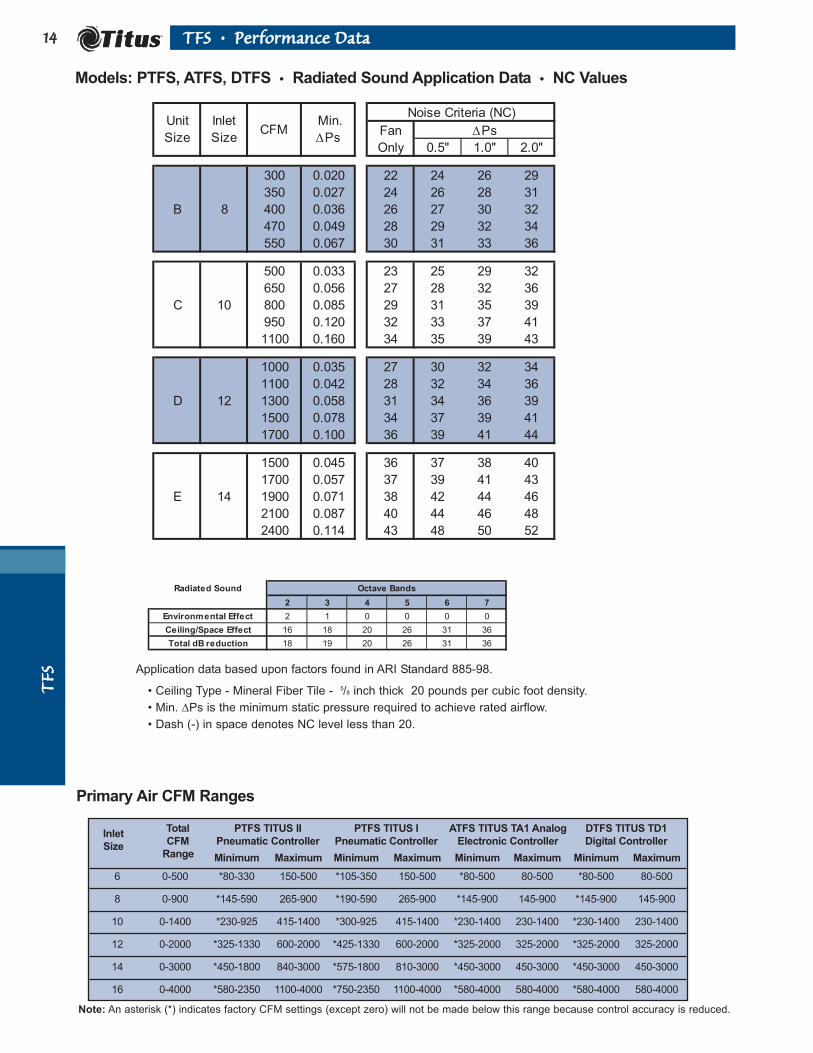
Primary Air CFM Ranges
TQS 2003 Data
R13 - Radiated NC
Fan
Only 0.5" 1.0" 2.0"
300 0.020 22 24 26 29
350 0.027 24 26 28 31
B 8 400 0.036 26 27 30 32
470 0.049 28 29 32 34
550 0.067 30 31 33 36
500 0.033 23 25 29 32
650 0.056 27 28 32 36
C 10 800 0.085 29 31 35 39
950 0.120 32 33 37 41
1100 0.160 34 35 39 43
1000 0.035 27 30 32 34
1100 0.042 28 32 34 36
D 12 1300 0.058 31 34 36 39
1500 0.078 34 37 39 41
1700 0.100 36 39 41 44
1500 0.045 36 37 38 40
1700 0.057 37 39 41 43
E 14 1900 0.071 38 42 44 46
2100 0.087 40 44 46 48
2400 0.114 43 48 50 52
Noise Criteria (NC)Unit
Size
Inlet
SizeCFM
Min.
∆Ps∆Ps
Radiated Sound Octave Bands
2 3 4 5 6 7
Environmental Effect 2 1 0 0 0 0
Ceiling/Space Effect 16 18 20 26 31 36
Total dB reduction 18 19 20 26 31 36
Models: PTFS, ATFS, DTFS • Radiated Sound Application Data • NC Values
Note: An asterisk (*) indicates factory CFM settings (except zero) will not be made below this range because control accuracy is reduced.
Application data based upon factors found in ARI Standard 885-98.
• Ceiling Type - Mineral Fiber Tile - 5/8 inch thick 20 pounds per cubic foot density.
• Min. ∆Ps is the minimum static pressure required to achieve rated airflow.
• Dash (-) in space denotes NC level less than 20.
InletTotal PTFS TITUS II PTFS TITUS I ATFS TITUS TA1 Analog DTFS TITUS TD1
SizeCFM Pneumatic Controller Pneumatic Controller Electronic Controller Digital Controller
Range Minimum Maximum Minimum Maximum Minimum Maximum Minimum Maximum
6 0-500 *80-330 150-500 *105-350 150-500 *80-500 80-500 *80-500 80-500
8 0-900 *145-590 265-900 *190-590 265-900 *145-900 145-900 *145-900 145-900
10 0-1400 *230-925 415-1400 *300-925 415-1400 *230-1400 230-1400 *230-1400 230-1400
12 0-2000 *325-1330 600-2000 *425-1330 600-2000 *325-2000 325-2000 *325-2000 325-2000
14 0-3000 *450-1800 840-3000 *575-1800 810-3000 *450-3000 450-3000 *450-3000 450-3000
16 0-4000 *580-2350 1100-4000 *750-2350 1100-4000 *580-4000 580-4000 *580-4000 580-4000

TTFFSS
1155TTFFSS •• PPeerrffoorrmmaannccee DDaattaa
Models: PTFS, ATFS, DTFS • Discharge Sound Application Data • NC Values
Fan
Only 0.5" 1.0" 2.0"
300 0.020 - - - -
350 0.027 - - - 21
B 8 400 0.036 - - 21 23
470 0.049 23 21 23 25
550 0.067 27 24 25 27
500 0.033 27 28 29 29
650 0.056 28 30 30 31
C 10 800 0.085 28 31 31 32
950 0.120 29 32 32 33
1100 0.160 30 32 33 33
1000 0.035 25 32 33 35
1100 0.042 26 34 35 36
D 12 1300 0.058 29 36 38 39
1500 0.078 30 38 39 40
1700 0.100 34 41 42 44
1500 0.045 32 41 43 44
1700 0.057 35 44 45 46
E 14 1900 0.071 36 45 46 48
2100 0.087 38 48 49 50
2400 0.114 40 50 52 53
Unit
Size
Inlet
SizeCFM
Min.
∆Ps∆Ps
Noise Criteria (NC)
Discharge Sound O ctave Bands
2 3 4 5 6 7
Environm ental Effect 2 1 0 0 0 0
Duct Lining 3 6 12 25 29 18
End Reflection 9 5 2 0 0 0Flex Duct 6 10 18 20 21 12
Space Effect 5 6 7 8 9 10Total dB reduction 25 28 39 53 59 40
O ctave Bands2 3 4 5 6 7
300-700 CFM 2 1 1 -2 -5 -1O ver 700 CFM 4 3 2 -2 -7 -1
• Flex Duct - Vinyl Core Flex.
• End Reflection - 8-inch termination to Diffuser.
• Fiberglass Flex Duct - 5-foot length, 1-inch duct work.
• Room Size - 2400 Cubic Feet Room, 5 feet from sound source.
• Min. ∆Ps is the minimum static pressure required to achieve rated airflow.
• Dash (-) in space denotes NC level less than 20.
The following dB adjustments are used, per ARI 885-98, for the calculation of NC above 300 CFM.
TTFFSS
1166 TTFFSS •• PPeerrffoorrmmaannccee DDaattaa
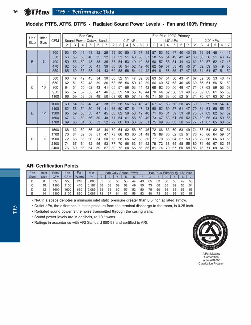
Fan Plus 100% Primary
CFM Sound Power Octave Bands
2 3 4 5 6 7 2 3 4 5 6 7 2 3 4 5 6 7 2 3 4 5 6 7
300 53 50 48 43 32 29 55 50 50 46 37 35 57 53 52 47 40 40 58 56 54 48 44 45
350 56 53 50 46 35 32 57 52 51 48 38 37 58 55 54 49 42 42 60 58 56 51 46 47
B 400 59 55 52 48 38 36 58 54 53 49 40 38 60 57 55 51 44 43 62 60 57 52 47 48
470 62 58 54 50 41 39 60 56 54 52 42 40 62 59 57 53 45 45 64 62 59 55 49 50
550 65 60 55 53 44 43 62 58 56 54 44 42 64 61 58 55 47 47 65 64 61 57 51 52
500 60 47 49 43 34 30 60 52 51 47 39 36 63 57 54 50 43 41 67 62 58 53 48 47
650 62 51 52 48 39 36 63 55 54 50 42 39 66 60 57 53 46 45 69 65 61 56 51 50
C 800 64 54 55 52 43 41 65 57 56 53 44 42 68 62 60 56 49 47 71 67 63 59 53 53
950 65 57 57 55 47 46 66 59 58 55 46 44 70 64 62 58 51 49 73 69 65 61 55 55
1100 66 59 59 58 49 50 68 60 60 57 48 46 71 56 63 60 52 51 74 70 67 63 57 57
1000 60 54 52 48 42 38 65 58 56 53 46 42 67 61 58 56 50 45 69 63 59 58 54 48
1100 62 56 54 50 44 41 66 60 57 54 47 43 68 62 59 57 51 47 70 64 61 59 55 50
D 1300 65 59 56 53 47 45 68 62 59 56 49 46 71 65 61 59 53 49 73 67 63 62 57 52
1500 67 61 59 56 50 48 71 64 61 58 50 49 73 67 63 61 55 52 75 69 65 63 59 55
1700 69 63 61 58 53 52 72 66 63 60 52 51 75 69 65 63 56 54 77 71 67 65 60 57
1500 68 62 60 56 48 44 70 64 62 58 50 46 72 66 63 60 53 49 74 68 64 62 57 51
1700 70 64 62 58 51 47 73 66 63 60 51 48 75 68 65 62 55 51 76 70 66 64 59 54
E 1900 72 65 63 60 54 50 75 68 65 62 53 50 77 70 66 64 57 53 78 72 68 66 60 56
2100 74 67 64 62 56 53 77 70 66 63 54 52 79 72 68 65 58 55 80 74 69 67 62 58
2400 76 69 66 64 59 57 80 72 68 65 56 55 81 74 70 67 60 58 83 76 71 69 64 60
0.5" ∆Ps 1.0" ∆Ps 2.0" ∆PsUnit
Size
Inlet
Size
Fan Only
14
8
10
12
Fan Inlet Prim. Fan Min
Size Size CFM CFM Ps 2 3 4 5 6 7 2 3 4 5 6 7
B 8 550 550 210 0.068 65 60 55 53 44 43 65 63 60 56 49 50
C 10 1100 1100 410 0.161 66 59 59 58 49 50 73 68 65 62 55 54
D 12 1600 1600 680 0.089 68 62 60 57 52 50 75 69 65 63 58 55
E 14 2100 2100 860 0.087 73 67 64 62 56 53 80 73 69 66 60 57
Fan Only Sound PowerFan
Watts
Fan Plus Primary @ 1.5" Inlet
Models: PTFS, ATFS, DTFS • Radiated Sound Power Levels • Fan and 100% Primary
VA
RIA
BLE
AIR
VO
LU
ME
A ParticipatingCorporation
in the ARI 880Certification Program
ARI Certification Points
• N/A in a space denotes a minimum inlet static pressure greater than 0.5 inch at rated airflow.
• Outlet ∆Ps, the difference in static pressure from the terminal discharge to the room, is 0.25 inch.
• Radiated sound power is the noise transmitted through the casing walls.
• Sound power levels are in decibels, re 10-12 watts.
• Ratings in accordance with ARI Standard 880-98 and certified to ARI.

TTFFSS
1177TTFFSS •• PPeerrffoorrmmaannccee DDaattaa
Fan Plus 100% Primary
CFM Sound Power Octave Bands
2 3 4 5 6 7 2 3 4 5 6 7 2 3 4 5 6 7 2 3 4 5 6 7
300 61 51 50 51 49 46 63 54 52 53 53 51 65 56 52 53 53 50 67 57 53 52 53 50
350 64 54 52 53 52 49 65 56 54 55 55 53 67 57 54 55 55 53 68 59 54 54 55 53
B 400 67 57 54 55 54 52 66 58 55 56 57 55 68 59 55 56 57 55 70 60 56 56 57 55
470 70 60 56 57 57 55 68 60 57 59 59 58 70 61 57 58 59 57 71 62 57 58 59 57
550 73 63 58 60 60 58 69 61 59 61 61 60 71 63 59 60 61 60 73 64 59 60 61 60
500 72 53 52 51 51 49 74 54 53 52 52 50 74 56 54 52 52 51 75 58 54 53 52 51
650 73 57 56 56 56 54 75 59 57 57 57 56 75 60 58 57 57 57 76 62 58 57 57 57
C 800 74 60 58 60 60 59 76 62 60 61 61 61 76 64 61 61 61 61 76 65 61 61 62 62
950 74 63 61 63 63 62 76 65 63 64 64 64 77 67 63 64 65 65 77 68 63 65 65 65
1100 75 65 63 65 65 65 77 67 65 67 67 67 77 69 65 67 68 68 78 71 65 67 68 68
1000 73 61 55 56 61 59 79 67 62 64 67 67 80 68 63 66 64 65 81 69 63 67 60 62
1100 74 63 57 58 63 61 80 68 64 65 68 68 81 69 64 67 65 66 82 70 65 68 61 63
D 1300 76 66 61 62 66 65 82 71 66 67 70 70 83 72 66 68 66 67 84 72 67 70 63 65
1400 77 68 62 64 67 66 83 72 67 67 70 70 84 73 67 69 67 68 85 73 68 71 64 65
1700 79 72 66 69 71 70 86 74 69 70 72 72 87 75 70 71 69 69 88 76 70 73 66 67
1500 79 73 65 67 69 66 86 76 67 68 71 70 87 77 70 72 70 71 88 77 71 74 70 71
1700 81 75 67 70 71 69 88 78 70 68 72 71 89 79 72 74 72 72 90 79 73 75 72 72
E 1900 82 76 68 72 73 71 89 80 72 70 73 72 90 80 74 75 73 73 91 80 74 77 73 73
2100 83 78 70 73 75 74 91 81 73 72 75 73 92 82 75 76 74 74 93 82 75 78 75 74
2400 83 80 72 76 77 77 93 84 76 75 76 75 94 84 77 78 75 75 95 84 77 79 76 75
14
8
10
12
0.5" ∆Ps 1.0" ∆Ps 2.0" ∆PsUnit
Size
Inlet
Size
Fan Only
Models: PTFS, ATFS, DTFS • Discharge Sound Power Levels • Fan and 100% Primary
VA
RIA
BLE
AIR
VO
LU
ME
A ParticipatingCorporation
in the ARI 880Certification Program
Fan Inlet Rated Fan Min
Size Size CFM CFM Ps 2 3 4 5 6 7
B 8 550 550 210 0.068 73 63 58 60 60 58
C 10 1100 1100 430 0.161 75 65 63 65 65 65
D 12 1600 1600 690 0.089 74 69 67 69 70 66
E 14 2100 2100 870 0.087 79 74 71 74 74 69
Fan Only Sound PowerFan
Watts
• N/A in a space denotes a minimum inlet static pressure greater than 0.5 inch at rated airflow.
• Outlet ∆Ps, the difference in static pressure from the terminal discharge to the room, is 0.25 inch.
• Discharge sound power is the noise emitted from the unit discharge into the downstream duct.
• Sound power levels are in decibels, re 10-12 watts.
• Ratings in accordance with ARI Standard 880-98 and certified to ARI.
ARI Certification Points
TTFFSS
1188 TTFFSS •• PPeerrffoorrmmaannccee DDaattaa
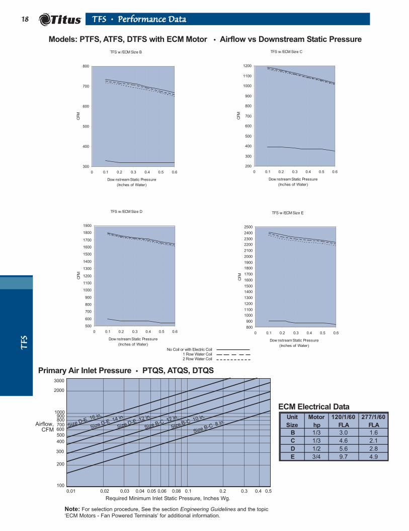
Primary Air Inlet Pressure • PTQS, ATQS, DTQS
Required Minimum Inlet Static Pressure, Inches Wg.
0.01 0.02 0.03 0.04 0.05 0.06 0.08 0.2 0.3 0.4 0.50.1
Airflow,CFM
200
300
400
500
600700800900
1000
Size D-E 16 in.
Size D-E 14 in.
Size D-E 12 in.
Size B-C 12 in.
Size B-C 10 in.
Size B-C 8 in.
2000
3000
100
Note: For selection procedure, See the section Engineering Guidelines and the topic
‘ECM Motors - Fan Powered Terminals’ for additional information.
Models: PTFS, ATFS, DTFS with ECM Motor • Airflow vs Downstream Static Pressure
ECM Electrical Data
B 1/3 3.0 1.6
C 1/3 4.6 2.1
D 1/2 5.6 2.8
E 3/4 9.7 4.9
Unit
Size
Motor
hp
120/1/60
FLA
277/1/60
FLA
TFS w /ECM Size B
300
400
500
600
700
800
0 0.1 0.2 0.3 0.4 0.5 0.6
Dow nstream Static Pressure
(Inches of Water)
CFM
TFS w /ECM Size C
200
300
400
500
600
700
800
900
1000
1100
1200
0 0.1 0.2 0.3 0.4 0.5 0.6
Dow nstream Static Pressure
(Inches of Water)
CFM
TFS w /ECM Size D
500
600
700
800
900
1000
1100
1200
1300
1400
1500
1600
1700
1800
1900
0 0.1 0.2 0.3 0.4 0.5 0.6
Dow nstream Static Pressure
(Inches of Water)
CFM
TFS w /ECM Size E
800
900
1000
1100
1200
1300
1400
1500
1600
1700
1800
1900
2000
2100
2200
2300
2400
2500
0 0.1 0.2 0.3 0.4 0.5 0.6
Dow nstream Static Pressure
(Inches of Water)
CFM
No Coil or with Electric Coil1 Row Water Coil2 Row Water Coil
TTFFSS
1199TTFFSS •• PPeerrffoorrmmaannccee DDaattaa
Fan
Only 0.5" 1.0" 2.0"
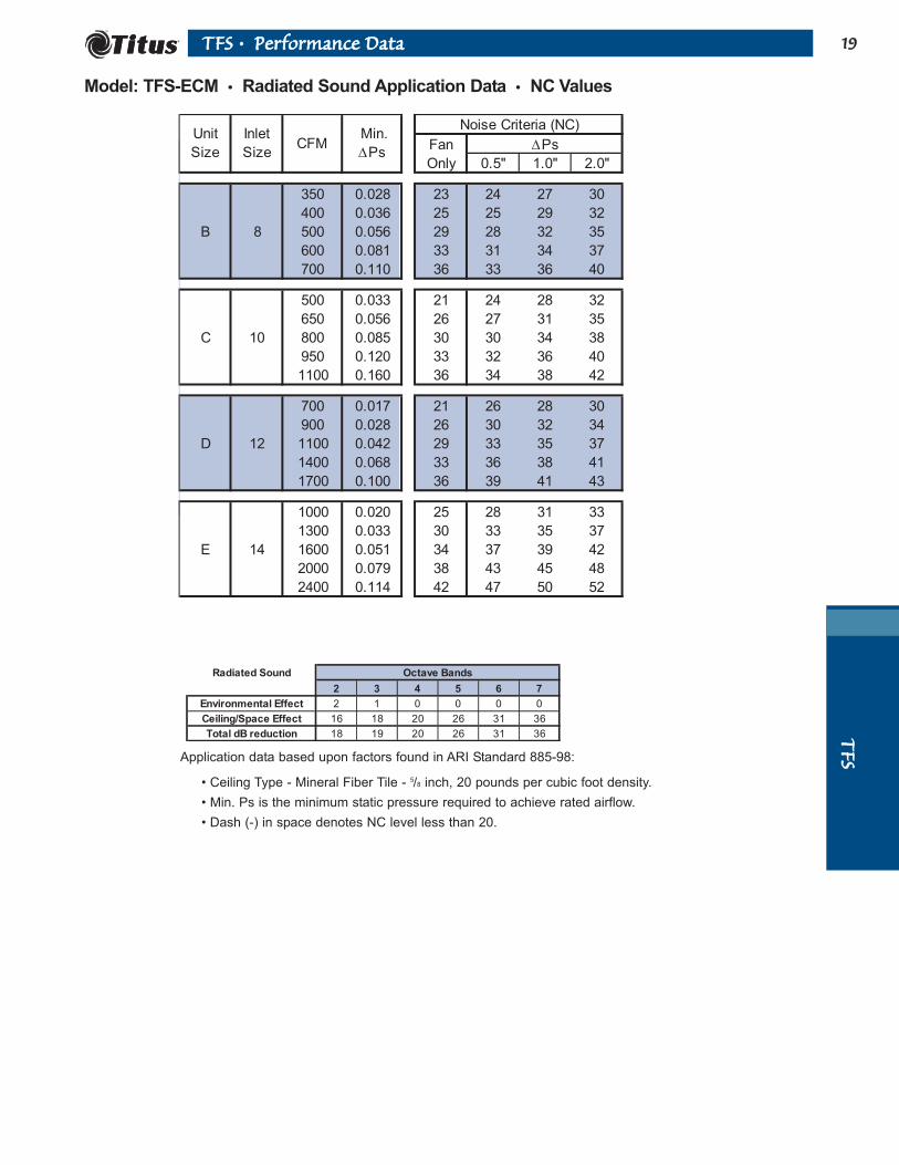
350 0.028 23 24 27 30
400 0.036 25 25 29 32
B 8 500 0.056 29 28 32 35
600 0.081 33 31 34 37
700 0.110 36 33 36 40
500 0.033 21 24 28 32
650 0.056 26 27 31 35
C 10 800 0.085 30 30 34 38
950 0.120 33 32 36 40
1100 0.160 36 34 38 42
700 0.017 21 26 28 30
900 0.028 26 30 32 34
D 12 1100 0.042 29 33 35 37
1400 0.068 33 36 38 41
1700 0.100 36 39 41 43
1000 0.020 25 28 31 33
1300 0.033 30 33 35 37
E 14 1600 0.051 34 37 39 42
2000 0.079 38 43 45 48
2400 0.114 42 47 50 52
Noise Criteria (NC)
∆PsUnit
Size
Inlet
SizeCFM
Min.
∆Ps
Model: TFS-ECM • Radiated Sound Application Data • NC Values
Radiated Sound Octave Bands
2 3 4 5 6 7
Environmental Effect 2 1 0 0 0 0
Ceiling/Space Effect 16 18 20 26 31 36
Total dB reduction 18 19 20 26 31 36
Application data based upon factors found in ARI Standard 885-98:
• Ceiling Type - Mineral Fiber Tile - 5/8 inch, 20 pounds per cubic foot density.
• Min. Ps is the minimum static pressure required to achieve rated airflow.
• Dash (-) in space denotes NC level less than 20.

TTFFSS
2200 TTFFSS •• PPeerrffoorrmmaannccee DDaattaa
Model: TFS-ECM • Discharge Sound Application Data • NC Values
Fan
Only 0.5" 1.0" 2.0"
350 0.028 24 - - -
400 0.036 25 - - -
B 8 500 0.056 26 20 21 22
600 0.081 28 24 25 26
700 0.110 26 28 28 28
500 0.033 21 - - -
650 0.056 23 - 20 22
C 10 800 0.085 24 23 24 24
950 0.120 26 27 27 28
1100 0.160 27 30 31 31
700 0.017 20 - - -
900 0.028 22 - - 20
D 12 1100 0.042 24 23 24 25
1400 0.068 27 28 30 31
1700 0.100 29 33 34 35
1000 0.020 - - - -
1300 0.033 25 22 22 23
E 14 1600 0.051 30 27 28 28
2000 0.079 36 33 33 34
2400 0.114 40 38 38 39
Noise Criteria (NC)
∆PsUnit
Size
Inlet
SizeCFM
Min.
∆Ps
Discharge Sound O ctave Bands
2 3 4 5 6 7
Environm ental Effect 2 1 0 0 0 0
Duct Lining 3 6 12 25 29 18
End Reflection 9 5 2 0 0 0
Flex Duct 6 10 18 20 21 12
Space Effect 5 6 7 8 9 10
Total dB reduction 25 28 39 53 59 40
Application Data are based upon factors found in ARI Standard 885-98 plus flow division as follows:
• Flex Duct - Vinyl Core Flex.
• End Reflection - 8-inch Termination to Diffuser.
• Fiberglass Flex Duct - 5-foot length, 1-inch Duct work.
• Room Size - 2400 Cubic Feet Room, 5 feet from sound source.
• Min. Ps is the minimum static pressure required to achieve rated airflow.
• Dash (-) in space denotes NC level less than 20.
The following dB adjustments are used, per ARI 885-98, for the calculation of NC above 300 CFM.
O ctave Bands
2 3 4 5 6 7
300-700 CFM 2 1 1 -2 -5 -1
O ver 700 CFM 4 3 2 -2 -7 -1

TTFFSS
2211TTFFSS •• PPeerrffoorrmmaannccee DDaattaa
Fan Plus 100% Primary
CFM Sound Power Octave Bands
2 3 4 5 6 7 2 3 4 5 6 7 2 3 4 5 6 7 2 3 4 5 6 7
350 56 53 48 46 36 34 56 53 49 47 39 37 57 55 52 49 42 42 59 58 55 51 46 47
400 59 55 51 49 39 37 58 55 51 49 40 38 59 57 54 51 44 43 61 60 57 53 48 48
B 500 63 59 54 52 43 42 61 58 54 52 43 41 63 61 57 54 46 46 64 63 60 55 50 51
600 67 63 57 55 46 46 64 61 56 54 45 43 65 63 59 56 49 48 67 66 62 58 52 53
700 70 66 59 57 49 49 66 63 58 56 46 45 68 66 61 58 50 50 69 69 64 60 54 55
500 46 43 47 43 34 30 56 52 50 46 38 36 60 57 53 49 43 41 64 62 57 52 48 47
650 53 50 52 48 39 37 59 54 53 49 41 39 63 59 56 52 46 44 67 65 60 55 50 50
C 800 59 55 55 52 44 42 62 56 55 52 43 41 66 61 59 55 48 47 70 67 62 58 53 52
950 64 59 58 55 47 47 64 58 57 54 45 43 68 63 61 57 50 49 72 68 64 60 55 54
1100 69 62 61 58 51 50 65 59 59 56 47 45 69 64 62 59 52 50 73 70 66 62 56 56
700 55 49 47 43 37 32 58 53 52 48 42 37 60 56 54 51 46 41 63 58 56 54 51 44
900 59 53 51 48 41 37 61 57 55 52 45 41 64 59 57 54 49 44 66 62 59 57 54 48
D 1100 61 56 54 51 45 42 64 60 58 54 47 44 67 62 60 57 51 47 69 65 62 60 56 50
1400 65 60 58 55 49 48 68 63 61 57 49 48 70 66 63 60 54 51 73 69 65 63 59 54
1700 68 63 61 58 53 52 71 66 64 59 52 50 73 69 66 62 56 54 76 72 68 65 61 57
1000 57 51 50 48 38 33 62 55 54 52 44 38 64 58 56 54 48 41 66 60 58 57 52 45
1300 63 57 55 53 44 40 67 60 58 56 47 43 69 63 60 58 52 46 71 65 62 60 56 50
E 1600 67 61 59 56 49 45 71 64 61 59 50 46 74 67 63 61 54 50 76 69 65 63 59 53
2000 71 65 63 60 54 51 76 68 65 62 53 50 78 71 67 64 57 54 80 73 69 66 61 57
2400 75 69 66 64 58 56 79 72 68 64 55 54 82 74 70 67 60 57 84 77 72 69 64 61
Unit
Size
Inlet
Size
8
10
12
14
Fan Only
0.5" ∆Ps 1.0" ∆Ps 2.0" ∆Ps
Model: TFS-ECM • Radiated Sound Power Data
• N/A in a space denotes a minimum inlet static pressure greater than 0.5 inch at rated airflow.
• Outlet ∆Ps, the difference in static pressure from the terminal discharge to the room, is 0.25 inch.
• Radiated sound power is the noise transmitted through the casing walls.
• Sound power levels are in decibels, re 10-12 watts.
• Ratings in accordance with ARI Standard 880 and certified to ARI.
VA
RIA
BLE
AIR
VO
LU
ME
A ParticipatingCorporation
in the ARI 880Certification Program
Fan Inlet Prim. Fan Min
Size Size CFM CFM Ps 2 3 4 5 6 7 2 3 4 5 6 7
B 8 700 700 210 0.110 70 66 59 57 49 49 69 67 63 59 52 53
C 10 1100 1100 280 0.161 69 62 61 58 51 50 72 67 64 60 54 54
D 12 1600 1600 390 0.089 67 62 60 57 52 51 74 70 66 63 58 55
E 14 2100 2100 580 0.087 72 66 64 61 55 53 80 73 69 66 60 57
Fan
Watts
Fan Only Sound Power Fan Plus Primary @ 1.5" Inlet
ARI Certification Points
TTFFSS
2222 TTFFSS •• PPeerrffoorrmmaannccee DDaattaa
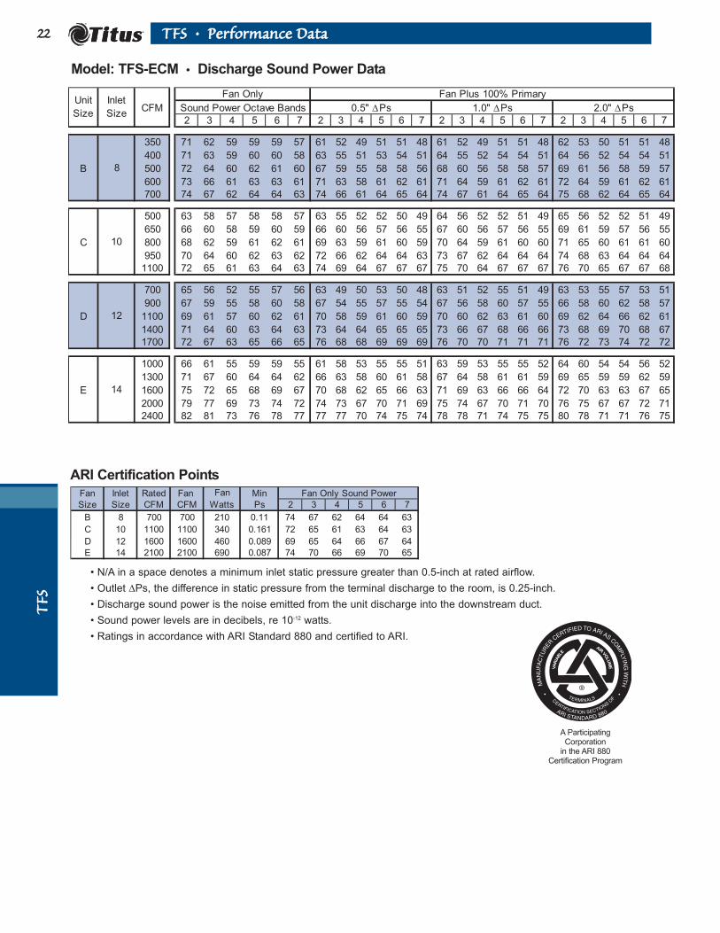
Model: TFS-ECM • Discharge Sound Power Data
Fan Plus 100% Primary
CFM Sound Power Octave Bands
2 3 4 5 6 7 2 3 4 5 6 7 2 3 4 5 6 7 2 3 4 5 6 7
350 71 62 59 59 59 57 61 52 49 51 51 48 61 52 49 51 51 48 62 53 50 51 51 48
400 71 63 59 60 60 58 63 55 51 53 54 51 64 55 52 54 54 51 64 56 52 54 54 51
B 500 72 64 60 62 61 60 67 59 55 58 58 56 68 60 56 58 58 57 69 61 56 58 59 57
600 73 66 61 63 63 61 71 63 58 61 62 61 71 64 59 61 62 61 72 64 59 61 62 61
700 74 67 62 64 64 63 74 66 61 64 65 64 74 67 61 64 65 64 75 68 62 64 65 64
500 63 58 57 58 58 57 63 55 52 52 50 49 64 56 52 52 51 49 65 56 52 52 51 49
650 66 60 58 59 60 59 66 60 56 57 56 55 67 60 56 57 56 55 69 61 59 57 56 55
C 800 68 62 59 61 62 61 69 63 59 61 60 59 70 64 59 61 60 60 71 65 60 61 61 60
950 70 64 60 62 63 62 72 66 62 64 64 63 73 67 62 64 64 64 74 68 63 64 64 64
1100 72 65 61 63 64 63 74 69 64 67 67 67 75 70 64 67 67 67 76 70 65 67 67 68
700 65 56 52 55 57 56 63 49 50 53 50 48 63 51 52 55 51 49 63 53 55 57 53 51
900 67 59 55 58 60 58 67 54 55 57 55 54 67 56 58 60 57 55 66 58 60 62 58 57
D 1100 69 61 57 60 62 61 70 58 59 61 60 59 70 60 62 63 61 60 69 62 64 66 62 61
1400 71 64 60 63 64 63 73 64 64 65 65 65 73 66 67 68 66 66 73 68 69 70 68 67
1700 72 67 63 65 66 65 76 68 68 69 69 69 76 70 70 71 71 71 76 72 73 74 72 72
1000 66 61 55 59 59 55 61 58 53 55 55 51 63 59 53 55 55 52 64 60 54 54 56 52
1300 71 67 60 64 64 62 66 63 58 60 61 58 67 64 58 61 61 59 69 65 59 59 62 59
E 1600 75 72 65 68 69 67 70 68 62 65 66 63 71 69 63 66 66 64 72 70 63 63 67 65
2000 79 77 69 73 74 72 74 73 67 70 71 69 75 74 67 70 71 70 76 75 67 67 72 71
2400 82 81 73 76 78 77 77 77 70 74 75 74 78 78 71 74 75 75 80 78 71 71 76 75
Unit
Size
Inlet
Size
Fan Only
0.5" ∆Ps 1.0" ∆Ps 2.0" ∆Ps
8
10
12
14
• N/A in a space denotes a minimum inlet static pressure greater than 0.5-inch at rated airflow.
• Outlet ∆Ps, the difference in static pressure from the terminal discharge to the room, is 0.25-inch.
• Discharge sound power is the noise emitted from the unit discharge into the downstream duct.
• Sound power levels are in decibels, re 10-12 watts.
• Ratings in accordance with ARI Standard 880 and certified to ARI.
VA
RIA
BLE
AIR
VO
LU
ME
A ParticipatingCorporation
in the ARI 880Certification Program
Fan Inlet Rated Fan Min
Size Size CFM CFM Ps 2 3 4 5 6 7
B 8 700 700 210 0.11 74 67 62 64 64 63
C 10 1100 1100 340 0.161 72 65 61 63 64 63
D 12 1600 1600 460 0.089 69 65 64 66 67 64
E 14 2100 2100 690 0.087 74 70 66 69 70 65
Fan
Watts
Fan Only Sound Power
ARI Certification Points
TTFFSS--FF FFaannttoomm
IIQQ2233TTFFSS--FF •• DDeessccrriippttiioonn
height width
6 6 5 7/8 2 7/8
8 6 7 7/8 2 7/8
10 7 9 7/8 4 7/8
12 8 11 7/8 4 7/8
6 6 5 7/8 2 7/8
8 6 7 7/8 2 7/8
10 7 9 7/8 4 7/8
12 8 11 7/8 4 7/8
10 7 9 7/8 4 7/8
12 8 11 7/8 4 7/8
14 10 13 7/8 6 7/8
16 11 15 7/8 6 7/8
12 8 11 7/8 4 7/8
14 10 13 7/8 6 7/8
16 11 15 7/8 6 7/8
11 1/2 16 11 1/8 37
K
2 1/4
L
B
8 18 7/8 11 7/8 8 7/8 14 1/8
18 1/8
Induced Air InletB
39215 7/8 14 7/8 16 1/2 11 1/8 20 14 5/8
X Y D
E
Unit
Size
Inlet
SizeA
C
D
8
F G H JFilter
Size
11 x 14
18 x 17
Model TFS-F Series Unit
13 7/8
11 7/8
42
46 3/4
N W
Performance DataPTFS-F . . . . . . . . . . . . .24ATFS-F . . . . . . . . . . . . .24DTFS-F . . . . . . . . . . . . .24
SpecificationsPTFS-F . . . . . . . . . . . . .35ATFS-F . . . . . . . . . . . . .35DTFS-F . . . . . . . . . . . . .35
Primary Air Inlet with AeroCross Multipoint Center
Averaging Sensor
Induced Air Inlet
12
614
W F
G
H
JK
LY
A
B 338 N
X
D
20
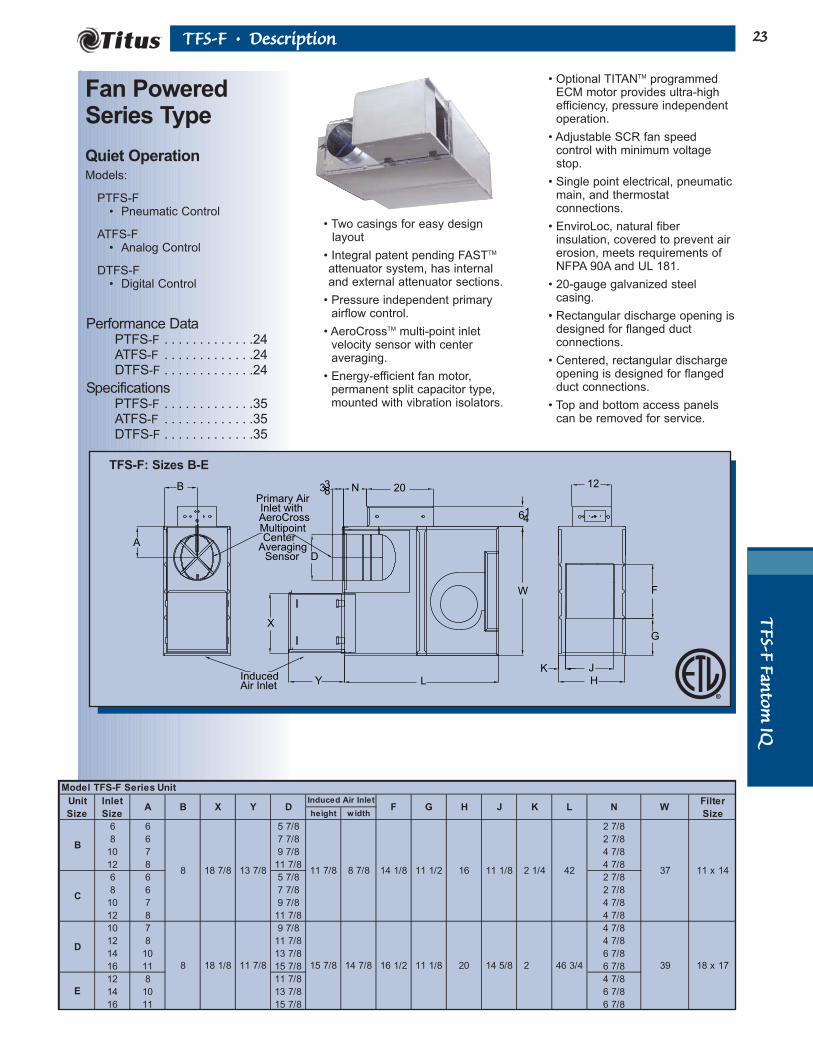
• Two casings for easy design layout
• Integral patent pending FASTTM
attenuator system, has internal and external attenuator sections.
• Pressure independent primaryairflow control.
• AeroCrossTM multi-point inletvelocity sensor with centeraveraging.
• Energy-efficient fan motor,permanent split capacitor type,mounted with vibration isolators.
• Optional TITANTM programmedECM motor provides ultra-highefficiency, pressure independentoperation.
• Adjustable SCR fan speedcontrol with minimum voltagestop.
• Single point electrical, pneumaticmain, and thermostatconnections.
• EnviroLoc, natural fiberinsulation, covered to prevent airerosion, meets requirements ofNFPA 90A and UL 181.
• 20-gauge galvanized steelcasing.
• Rectangular discharge opening isdesigned for flanged ductconnections.
• Centered, rectangular dischargeopening is designed for flangedduct connections.
• Top and bottom access panelscan be removed for service.
Fan PoweredSeries Type
Quiet OperationModels:
PTFS-F• Pneumatic Control
ATFS-F• Analog Control
DTFS-F• Digital Control
TFS-F: Sizes B-E

TTFFSS
--FF FF
aannttoo
mm IIQQ
2244 TTFFSS--FF •• DDiimmeennssiioonnss
9 S
R
1"
M
934 S
1" Typ.
R
U
6 14
1231
Heater Rack
Access Cover
Hot Water Coil Section
Standard Features
• 1/2-inch copper tubes.
• Aluminum ripple fins.
• Connections: Male solder. 5/8-inch for both 1- and 2-row.Left or right handconnections.
• Galvanized steel casing.
• Flanged duct connection.
• Coil is installed at dischargeof unit.
Coil Rows
• 1-Row
• 2-Row
Note: R and S are inside dimensions.
Electric Coil Section
Standard Features
• Automatic reset thermalcutouts, one per element.
• Single point electrical connection for entire unit, including coil.
• Positive pressure air flowswitch.
• Flanged duct connection.
• Coil is installed atdischarge of unit.
• Preset P/E switches withpneumatic units.
• 80/20 nickel chromeelement wire
• Transformers (analog anddigital models only)
Unit Size M (1-Row) M (2-Row) R S
B, C 1 1 20 1/2 12 1/2
D, E 1 1 1/4 25 17 1/2
Hot Water Coil Section (Discharge Mounted)
Unit Size U R S T
B, C 11 3/8 14 1/2 11 1/2 2 3/8
D, E 11 17 15 3 1/8
Electric Coil Section (Discharge Mounted)
B 1/6 2.3 0.9 0.8
C 1/4 4.0 1.8 1.4
D 1/3 8.5 3.6 3.0
E 3/4 8.6 4.2 4.5
277/1/60
FLA
120/1/60
FLA
208/240/1/60
FLA
Unit
Size
Motor
hp
Electrical Data
FLA = Full Load Amperage, as tested in accordance with UL 1995.
All fan motors are single phase, same voltage as electric coil(when supplied), with exception that 277V motors are used with480V, 3 phase coils (4 wire wye).
Additional Accessories (Optional)
• Induced air filter, 1-inch thick disposable
construction type.
• Fan disconnect switch (not available on
units with optional electric coils).
• 1-inch Liner.
• EnviroLoc Liner.
• Fibre-Free Liner.
• SteriLoc Liner.
• Fan unit fusing.
• Hanger brackets.
• Camlocks on fan access door.
Note: R and S are inside dimensions.
Options
• Mercury contactors.
• Fuse block.
• Disconnect switch,door interlock type.
• Manual resetcutout.
• Dust tightconstruction.
Supply Voltage
• 208V, 1 ph, 60 Hz.
• 240V, 1 ph, 60 Hz.
• 277V, 1 ph, 60 Hz.
• 208V, 3 ph, 60 Hz.
• 480V, 3 ph, 60 Hz. (4 wire wye only)

TTFFSS--FF FFaannttoomm
IIQQ2255TTFFSS--FF •• PPeerrffoorrmmaannccee DDaattaa
TFS-F Size C
300
400
500
600
700
800
900
1000
1100
1200
1300
0 0.1 0.2 0.3 0.4 0.5 0.6
Dow nstream Static Pressure
(Inches of Water)
CFM
TFS-F Size B
150
200
250
300
350
400
450
500
550
600
650
700
0 0.1 0.2 0.3 0.4 0.5 0.6
Dow nstream Static Pressure
(Inches of Water)
CFM
TFS-F Size D
700
800
900
1000
1100
1200
1300
1400
1500
1600
1700
1800
1900
2000
0 0.1 0.2 0.3 0.4 0.5 0.6
Dow nstream Static Pressure
(Inches of Water)
CFM
TFS-F Size E
1300
1400
1500
1600
1700
1800
1900
2000
2100
2200
2300
2400
2500
2600
2700
0 0.1 0.2 0.3 0.4 0.5 0.6
Dow nstream Static Pressure
(Inches of Water)
CFM
Models: PTFS-F, ATFS-F, DTFS-F • Airflow vs. Downstream Static Pressure
Primary Air Inlet Pressure • PTFS-F, ATFS-F, DTFS-F
Required Minimum Inlet Static Pressure, Inches Wg.0.01 0.02 0.03 0.04 0.05 0.06 0.08 0.2 0.3 0.4 0.50.1
Airflow,CFM
200
300
400
500
600700800900
1000
Size D-E 16 in.
Size D-E 14 in.
Size D-E 12 in.
Size B-C 12 in.
Size B-C 10 in.
Size B-C 8 in.
2000
3000
100
Note: For selection procedure, see the
Engineering Guidelines and the topic,
‘Sizing Basic Terminals from Capacity
Tables’.
No Coil or with Electric Coil1 Row Water Coil2 Row Water Coil

TTFFSS
--FF FF
aannttoo
mm IIQQ
2266 TTFFSS--FF •• PPeerrffoorrmmaannccee DDaattaa
Models: PTFS-F, ATFS-F, DTFS-F • Water Coil Heating Capacity (MBH)
• Hot water capacities are in MBH.
• Data are based upon 180° F entering water 65° F entering air.
• HD (head) loss is in feet of water.
• Tables are based upon a temperature difference of 115° F between entering air andentering water. For other temperature differences multiply MBH values by factors below.
• Air temperature rise = 927 x MBH/CFM.
• Connections: All coils are 5/8-inch O.D. male solder.
• Coils are not for steam application.
• Water enters at lower coil connection to prevent air entrapment.
Correction factors for other entering conditions:
200 250 300 350 400 450 500 550 600
1.0 0.15 10.1 11.3 12.3 13.2 14.0 14.7 15.3 15.8 16.3
2.0 0.52 11.2 12.7 14.0 15.1 16.1 17.1 17.9 18.7 19.4
4.0 1.86 11.8 13.5 15.0 16.3 17.5 18.6 19.6 20.6 21.5
6.0 2.77 12.1 13.8 15.4 16.8 18.1 19.2 20.3 21.3 22.3
0.01 0.01 0.01 0.02 0.02 0.03 0.03 0.04 0.04
1.0 0.27 15.8 18.0 19.8 21.3 22.7 23.9 25.0 25.9 26.8
2.0 0.92 17.6 20.4 22.9 25.0 27.0 28.8 30.4 31.9 33.2
4.0 3.20 18.7 21.9 24.8 27.4 29.8 32.0 34.0 35.9 37.6
6.0 5.49 19.1 22.5 25.5 28.3 30.8 33.2 35.4 37.5 39.4
0.01 0.02 0.03 0.03 0.04 0.05 0.06 0.08 0.09
400 490 580 670 760 850 940 1030 1100
1.0 0.15 14.0 15.2 16.1 17.0 17.7 18.3 18.9 19.4 19.7
2.0 0.52 16.1 17.7 19.1 20.3 21.4 22.3 23.2 24.0 24.5
4.0 1.86 17.5 19.4 21.1 22.6 23.9 25.1 26.3 27.3 28.0
6.0 2.77 18.1 20.1 21.9 23.5 25.0 26.3 27.5 28.6 29.5
0.02 0.03 0.04 0.05 0.07 0.08 0.10 0.12 0.13
1.0 0.27 22.7 24.8 26.5 27.9 29.1 30.1 31.0 31.8 32.4
2.0 0.92 27.0 30.1 32.7 35.0 37.0 38.7 40.3 41.8 42.8
4.0 3.20 29.8 33.6 36.9 39.9 42.6 45.1 47.3 49.3 50.8
6.0 5.49 30.8 35.0 38.6 41.9 44.9 47.6 50.1 52.5 54.2
0.04 0.06 0.08 0.11 0.14 0.17 0.20 0.24 0.27
800 925 1050 1175 1300 1425 1550 1675 1800
1.0 0.22 22.7 23.8 24.7 25.6 26.3 26.9 27.5 28.0 28.5
2.0 0.76 27.8 29.6 31.1 32.5 33.7 34.8 35.8 36.8 37.6
4.0 2.64 31.4 33.6 35.6 37.5 39.2 40.7 42.1 43.5 44.7
6.0 4.35 32.8 35.3 37.5 39.5 41.4 43.2 44.8 46.3 47.7
0.03 0.04 0.05 0.06 0.07 0.08 0.09 0.11 0.12
1.0 0.42 34.8 36.4 37.8 39.0 39.9 40.8 41.6 42.2 42.8
2.0 1.40 45.3 48.4 51.0 53.4 55.4 57.3 59.0 60.5 61.9
4.0 4.78 52.9 57.2 61.1 64.6 67.8 70.7 73.4 75.8 78.2
6.0 8.68 56.0 60.9 65.3 69.3 73.0 76.5 79.6 82.6 85.4
0.06 0.07 0.09 0.11 0.14 0.16 0.19 0.22 0.25
1400 1525 1650 1775 1900 2025 2150 2275 2400
1.0 0.22 26.8 27.4 27.9 28.4 28.9 29.3 29.7 30.0 30.4
2.0 0.76 34.6 35.6 36.6 37.5 38.3 39.1 39.8 40.4 41.1
4.0 2.64 40.4 41.9 43.2 44.5 45.6 47.7 47.8 48.8 49.7
6.0 4.35 42.8 44.5 46.0 47.4 47.8 50.0 51.3 52.4 53.5
0.08 0.09 0.11 0.12 0.14 0.15 0.17 0.19 0.21
1.0 0.42 50.6 41.4 42.1 42.7 43.3 43.8 44.2 N/A N/A
2.0 1.40 56.9 58.6 60.2 61.6 62.9 64.1 65.2 N/A N/A
4.0 4.78 70.1 72.8 75.4 77.7 79.9 81.9 83.9 N/A N/A
6.0 8.68 75.8 79.0 82.0 84.9 87.5 90.0 92.3 N/A N/A
0.16 0.18 0.21 0.24 0.27 0.31 0.34 N/A N/A
ETwo
Row
Airside ∆Ps
Airflow, CFM
EOne
Row
Airside ∆Ps
Unit
SizeRows GPM
DTwo
Row
Airside ∆Ps
Head
Loss
DOne
Row
Airside ∆Ps
Unit
SizeRows GPM
Head
Loss
CTwo
Row
Airside ∆Ps
Airflow, CFM
Airflow, CFM
COne
Row
Airside ∆Ps
Unit
SizeRows GPM
Head
Loss
BOne
Row
Airside ∆Ps
BTwo
Row
Airside ∆Ps
Airflow, CFMHead
LossGPM
Unit
SizeRows
∆∆T 50 60 70 80 90 100 115 125 140 150
Factor 0.44 0.52 0.61 0.70 0.79 0.88 1.00 1.07 1.20 1.30
TTFFSS--FF FFaannttoomm
IIQQ2277TTFFSS--FF •• PPeerrffoorrmmaannccee DDaattaa
Primary Air CFM Ranges
Fan
Only 0.5" 1.0" 2.0"
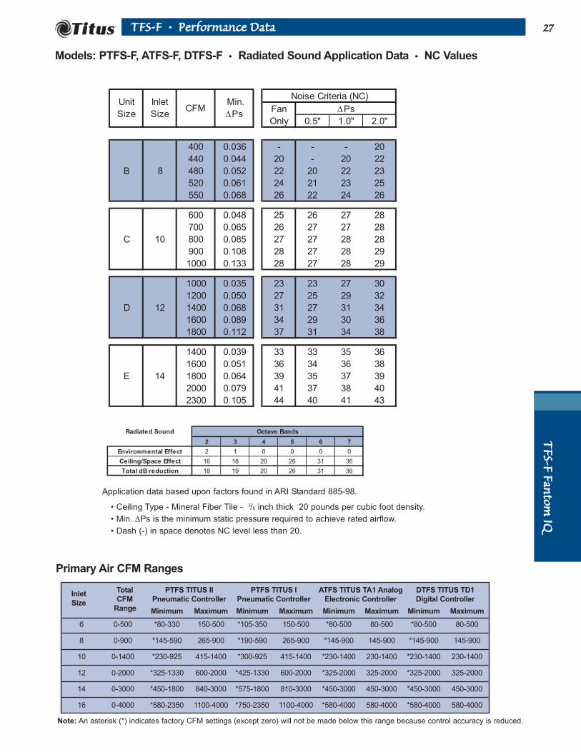
400 0.036 - - - 20
440 0.044 20 - 20 22
B 8 480 0.052 22 20 22 23
520 0.061 24 21 23 25
550 0.068 26 22 24 26
600 0.048 25 26 27 28
700 0.065 26 27 27 28
C 10 800 0.085 27 27 28 28
900 0.108 28 27 28 29
1000 0.133 28 27 28 29
1000 0.035 23 23 27 30
1200 0.050 27 25 29 32
D 12 1400 0.068 31 27 31 34
1600 0.089 34 29 30 36
1800 0.112 37 31 34 38
1400 0.039 33 33 35 36
1600 0.051 36 34 36 38
E 14 1800 0.064 39 35 37 39
2000 0.079 41 37 38 40
2300 0.105 44 40 41 43
Unit
Size
Inlet
SizeCFM
Min.
∆Ps
Noise Criteria (NC)
∆Ps
Radiated Sound Octave Bands
2 3 4 5 6 7
Environmental Effect 2 1 0 0 0 0
Ceiling/Space Effect 16 18 20 26 31 36
Total dB reduction 18 19 20 26 31 36
Models: PTFS-F, ATFS-F, DTFS-F • Radiated Sound Application Data • NC Values
Note: An asterisk (*) indicates factory CFM settings (except zero) will not be made below this range because control accuracy is reduced.
Application data based upon factors found in ARI Standard 885-98.
• Ceiling Type - Mineral Fiber Tile - 5/8 inch thick 20 pounds per cubic foot density.
• Min. ∆Ps is the minimum static pressure required to achieve rated airflow.
• Dash (-) in space denotes NC level less than 20.
InletTotal PTFS TITUS II PTFS TITUS I ATFS TITUS TA1 Analog DTFS TITUS TD1
SizeCFM Pneumatic Controller Pneumatic Controller Electronic Controller Digital Controller
Range Minimum Maximum Minimum Maximum Minimum Maximum Minimum Maximum
6 0-500 *80-330 150-500 *105-350 150-500 *80-500 80-500 *80-500 80-500
8 0-900 *145-590 265-900 *190-590 265-900 *145-900 145-900 *145-900 145-900
10 0-1400 *230-925 415-1400 *300-925 415-1400 *230-1400 230-1400 *230-1400 230-1400
12 0-2000 *325-1330 600-2000 *425-1330 600-2000 *325-2000 325-2000 *325-2000 325-2000
14 0-3000 *450-1800 840-3000 *575-1800 810-3000 *450-3000 450-3000 *450-3000 450-3000
16 0-4000 *580-2350 1100-4000 *750-2350 1100-4000 *580-4000 580-4000 *580-4000 580-4000
TTFFSS
--FF FF
aannttoo
mm IIQQ
2288 TTFFSS--FF •• PPeerrffoorrmmaannccee DDaattaa
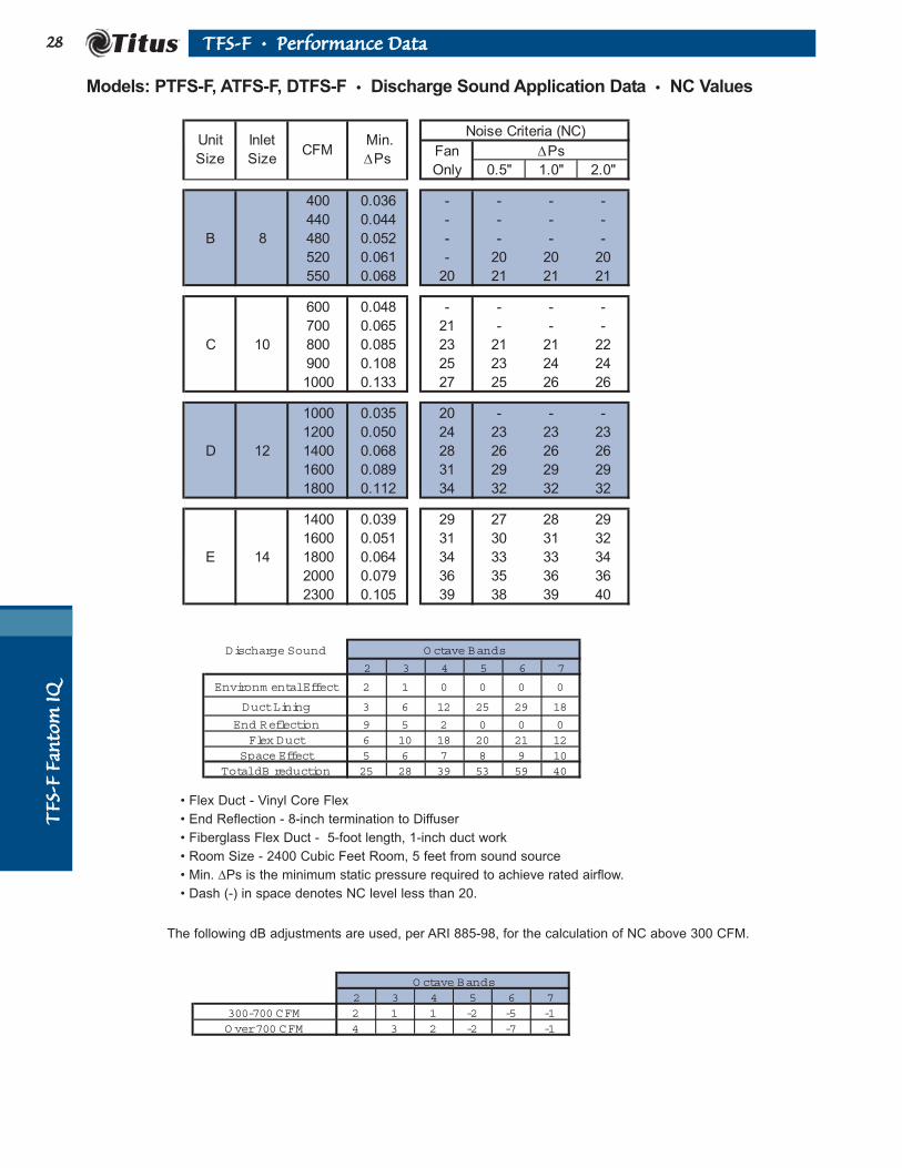
Models: PTFS-F, ATFS-F, DTFS-F • Discharge Sound Application Data • NC Values
Fan
Only 0.5" 1.0" 2.0"
400 0.036 - - - -
440 0.044 - - - -
B 8 480 0.052 - - - -
520 0.061 - 20 20 20
550 0.068 20 21 21 21
600 0.048 - - - -
700 0.065 21 - - -
C 10 800 0.085 23 21 21 22
900 0.108 25 23 24 24
1000 0.133 27 25 26 26
1000 0.035 20 - - -
1200 0.050 24 23 23 23
D 12 1400 0.068 28 26 26 26
1600 0.089 31 29 29 29
1800 0.112 34 32 32 32
1400 0.039 29 27 28 29
1600 0.051 31 30 31 32
E 14 1800 0.064 34 33 33 34
2000 0.079 36 35 36 36
2300 0.105 39 38 39 40
Noise Criteria (NC)
∆PsUnit
Size
Inlet
SizeCFM
Min.
∆Ps
Discharge Sound O ctave Bands
2 3 4 5 6 7
Environm ental Effect 2 1 0 0 0 0
Duct Lining 3 6 12 25 29 18
End Reflection 9 5 2 0 0 0Flex Duct 6 10 18 20 21 12
Space Effect 5 6 7 8 9 10Total dB reduction 25 28 39 53 59 40
O ctave Bands2 3 4 5 6 7
300-700 CFM 2 1 1 -2 -5 -1O ver 700 CFM 4 3 2 -2 -7 -1
• Flex Duct - Vinyl Core Flex
• End Reflection - 8-inch termination to Diffuser
• Fiberglass Flex Duct - 5-foot length, 1-inch duct work
• Room Size - 2400 Cubic Feet Room, 5 feet from sound source
• Min. ∆Ps is the minimum static pressure required to achieve rated airflow.
• Dash (-) in space denotes NC level less than 20.
The following dB adjustments are used, per ARI 885-98, for the calculation of NC above 300 CFM.

TTFFSS--FF FFaannttoomm
IIQQ2299TTFFSS--FF •• PPeerrffoorrmmaannccee DDaattaa
Fan Plus 100% Primary
CFM Sound Power Octave Bands
2 3 4 5 6 7 2 3 4 5 6 7 2 3 4 5 6 7 2 3 4 5 6 7
400 57 45 43 36 36 33 55 45 43 41 40 37 57 48 44 42 42 40 58 50 45 43 44 44
440 59 47 45 37 36 33 57 46 44 42 41 38 58 49 46 43 43 41 60 52 47 44 45 44
B 480 60 48 46 39 36 34 58 48 45 42 41 39 60 51 47 44 43 42 61 54 48 45 45 45
520 62 50 47 40 37 34 59 49 46 43 42 39 61 52 48 44 44 43 62 55 49 46 46 46
550 63 51 48 41 37 34 60 50 47 44 42 40 62 53 48 45 44 43 63 56 49 46 46 46
600 62 51 46 39 36 34 63 52 46 42 37 33 64 54 47 42 40 39 64 56 48 43 43 45
700 63 52 48 42 38 35 63 53 48 43 38 34 64 55 49 44 41 40 65 56 50 45 44 46
C 800 64 53 49 44 39 36 64 53 49 44 39 35 64 55 50 45 42 41 65 57 51 46 45 47
900 64 54 51 46 40 36 64 54 50 46 40 36 64 56 51 46 43 41 65 57 52 47 46 47
1000 65 55 52 48 41 37 64 54 51 47 41 36 65 56 52 47 44 42 65 58 53 48 46 48
1000 61 50 46 40 36 31 61 52 48 43 39 35 63 55 49 44 42 40 66 57 51 45 44 45
1200 64 53 49 44 39 35 63 54 50 45 42 38 65 57 51 46 44 42 68 59 53 47 47 47
D 1400 67 56 51 47 43 40 64 56 52 47 43 40 67 58 53 48 46 44 70 61 55 49 49 49
1600 69 58 53 50 45 43 65 57 54 49 45 41 68 60 55 50 48 46 71 63 56 51 50 51
1800 72 61 55 52 48 46 67 59 55 50 47 43 69 61 57 52 49 48 72 64 58 53 52 52
1400 69 61 55 50 45 40 69 60 53 48 44 40 70 61 54 49 46 44 71 63 56 50 49 48
1600 71 64 57 52 47 43 69 62 55 50 46 42 71 63 57 51 48 46 72 65 58 53 50 50
E 1800 73 66 59 54 50 46 70 63 57 52 47 43 72 65 58 53 50 47 73 66 60 54 52 52
2000 75 67 61 56 52 49 72 65 59 54 49 45 73 66 60 55 51 49 74 68 61 56 54 53
2300 77 70 63 58 55 53 74 66 61 56 51 47 75 68 62 57 53 51 76 69 64 58 56 55
12
14
1.0" ∆Ps 2.0" ∆Ps
8
10
Unit
Size
Inlet
Size
Fan Only
0.5" ∆Ps
Fan Inlet Prim. Fan Min
Size Size CFM CFM Ps 2 3 4 5 6 7 2 3 4 5 6 7
B 8 550 550 210 0.07 63 51 48 41 37 34 62 55 49 46 45 45
C 10 1050 1050 470 0.15 65 55 53 49 41 37 68 57 53 49 45 46
D 12 1600 1600 790 0.09 69 58 53 50 45 43 71 61 56 51 49 49
E 14 2100 2100 870 0.09 75 67 61 56 52 48 75 68 62 57 53 52
Fan Plus Primary @ 1.5" InletFan
Watts
Fan Only Sound Power
Models: PTFS-F, ATFS-F, DTFS-F • Radiated Sound Power Levels • Fan and 100% Primary
VA
RIA
BLE
AIR
VO
LU
ME
A ParticipatingCorporation
in the ARI 880Certification Program
ARI Certification Points
• N/A in a space denotes a minimum inlet static pressure greater than 0.5 inch at rated airflow.
• Outlet ∆Ps, the difference in static pressure from the terminal discharge to the room, is 0.25 inch.
• Radiated sound power is the noise transmitted through the casing walls.
• Sound power levels are in decibels, re 10-12 watts.
• Ratings in accordance with ARI Standard 880-98 and certified to ARI.

TTFFSS
--FF FF
aannttoo
mm IIQQ
3300 TTFFSS--FF •• PPeerrffoorrmmaannccee DDaattaa
Fan Plus 100% Primary
CFM Sound Power Octave Bands
2 3 4 5 6 7 2 3 4 5 6 7 2 3 4 5 6 7 2 3 4 5 6 7
400 62 51 53 51 51 49 62 54 53 54 52 50 62 54 53 54 52 51 62 54 52 54 52 51
440 64 53 54 53 53 51 64 56 54 55 54 52 64 56 54 55 54 53 64 56 54 55 54 53
B 480 65 55 55 54 54 52 65 58 56 57 55 54 66 58 55 57 56 54 66 58 55 56 56 55
520 66 57 56 56 56 54 67 59 57 58 57 56 67 59 57 58 57 56 67 59 56 58 57 56
550 67 58 56 57 56 55 68 60 58 59 58 57 68 60 57 59 58 57 68 60 57 59 58 58
600 65 60 55 54 54 52 63 58 54 53 52 50 64 59 54 53 52 51 65 60 54 53 53 51
700 67 62 57 57 57 56 64 60 56 56 55 54 65 61 56 56 55 54 66 61 55 56 55 55
C 800 69 64 59 59 59 59 65 61 57 58 57 57 66 62 57 58 58 57 67 62 57 58 58 58
900 70 66 60 61 61 61 66 63 59 60 59 59 67 63 59 60 60 60 68 64 58 60 60 60
1000 72 67 61 63 63 63 66 64 60 61 61 62 67 64 60 61 62 62 68 65 60 61 62 63
1000 63 60 57 58 58 56 64 61 56 57 56 55 66 61 56 56 56 55 69 61 56 56 56 55
1200 67 64 60 62 61 61 66 63 59 61 60 59 68 63 59 60 60 59 70 64 59 60 60 59
D 1400 71 67 63 65 65 64 67 65 61 64 63 63 69 65 61 63 63 63 72 66 61 63 63 62
1600 73 70 65 68 68 68 69 67 63 67 65 66 71 67 63 66 65 65 76 67 63 65 65 65
1800 76 72 67 70 70 70 70 68 65 69 68 68 72 69 65 68 68 68 74 69 65 68 68 68
1400 73 71 64 66 67 64 73 70 62 64 63 61 74 71 62 64 63 61 76 71 63 65 64 62
1600 76 74 66 68 69 67 75 72 65 66 66 64 77 73 65 67 66 64 78 74 65 68 67 65
E 1800 78 75 68 71 71 70 77 75 67 69 68 67 79 75 67 69 69 67 80 76 67 70 70 68
2000 80 77 69 73 74 73 79 77 69 71 71 69 80 77 69 72 71 70 82 78 69 72 72 71
2300 82 79 71 75 76 76 81 79 72 74 74 73 83 80 72 74 74 74 84 80 72 75 75 74
Unit
Size
Inlet
Size
Fan Only
0.5" ∆Ps 1.0" ∆Ps 2.0" ∆Ps
8
10
12
14
Models: PTFS-F, ATFS-F, DTFS-F • Discharge Sound Power Levels • Fan and 100% Primary
VA
RIA
BLE
AIR
VO
LU
ME
A ParticipatingCorporation
in the ARI 880Certification Program
Fan Inlet Rated Fan Min
Size Size CFM CFM Ps 2 3 4 5 6 7
B 8 550 550 210 0.068 67 58 56 57 56 55
C 10 1050 1050 450 0.147 72 68 62 64 64 65
D 12 1600 1600 800 0.089 73 70 65 68 68 68
E 14 2100 2100 870 0.087 80 77 70 73 73 73
Fan
Watts
Fan Only Sound Power
• N/A in a space denotes a minimum inlet static pressure greater than 0.5 inch at rated airflow.
• Outlet ∆Ps, the difference in static pressure from the terminal discharge to the room, is 0.25 inch.
• Discharge sound power is the noise emitted from the unit discharge into the downstream duct.
• Sound power levels are in decibels, re 10-12 watts.
• Ratings in accordance with ARI Standard 880-98 and certified to ARI.
ARI Certification Points

TTFFSS--FF FFaannttoomm
IIQQ3311TTFFSS--FF •• PPeerrffoorrmmaannccee DDaattaa
Models: PTFS-F, ATFS-F, DTFS-F with ECM Motor • Airflow vs Downstream Static Pressure
Primary Air Inlet Pressure • PTFS-F, ATFS-F, DTFS-F
Required Minimum Inlet Static Pressure, Inches Wg.
0.01 0.02 0.03 0.04 0.05 0.06 0.08 0.2 0.3 0.4 0.50.1
Airflow,CFM
200
300
400
500
600700800900
1000
Size D-E 16 in.
Size D-E 14 in.
Size D-E 12 in.
Size B-C 12 in.
Size B-C 10 in.
Size B-C 8 in.
2000
3000
100
Note: For selection procedure, See the section Engineering Guidelines and the topic
‘ECM Motors - Fan Powered Terminals’ for additional information.
ECM Electrical Data
B 1/3 3.0 1.6
C 1/3 4.6 2.1
D 1/2 5.6 2.8
E 3/4 9.7 4.9
Unit
Size
Motor
hp
120/1/60
FLA
277/1/60
FLA
TFS-F w /ECM Size B
300
400
500
600
700
800
0 0.1 0.2 0.3 0.4 0.5 0.6
Dow nstream Static Pressure
(Inches of Water)
CFM
TFS-F w /ECM Size C
200
300
400
500
600
700
800
900
1000
1100
1200
0 0.1 0.2 0.3 0.4 0.5 0.6
Dow nstream Static Pressure
(Inches of Water)
CFM
TFS-F w /ECM Size D
500
600
700
800
900
1000
1100
1200
1300
1400
1500
1600
1700
1800
1900
0 0.1 0.2 0.3 0.4 0.5 0.6
Dow nstream Static Pressure
(Inches of Water)
CFM
TFS-F w /ECM Size E
800
900
1000
1100
1200
1300
1400
1500
1600
1700
1800
1900
2000
2100
2200
2300
2400
2500
0 0.1 0.2 0.3 0.4 0.5 0.6
Dow nstream Static Pressure
(Inches of Water)
CFM
No Coil or with Electric Coil1 Row Water Coil2 Row Water Coil

TTFFSS
--FF FF
aannttoo
mm IIQQ
3322 TTFFSS--FF •• PPeerrffoorrmmaannccee DDaattaa
Fan
Only 0.5" 1.0" 2.0"
350 0.028 - - - 20
400 0.036 21 - 20 22
B 8 500 0.056 24 22 24 27
600 0.081 27 26 28 30
700 0.110 29 29 31 33
400 0.021 - - - -
500 0.033 - - - 21
C 10 600 0.048 20 - 20 23
800 0.085 25 21 24 27
1000 0.133 28 24 26 30
700 0.017 - - 20 24
900 0.028 - - 23 28
D 12 1100 0.042 23 22 29 31
1400 0.068 28 25 30 34
1700 0.100 32 28 33 37
1100 0.024 24 23 24 26
1300 0.033 28 26 27 30
E 14 1600 0.051 34 30 32 35
1900 0.071 39 35 37 40
2300 0.105 43 38 41 43
Noise Criteria (NC)
∆PsUnit
Size
Inlet
SizeCFM
Min.
∆Ps
Model: TFS-F-ECM • Radiated Sound Application Data • NC Values
Radiated Sound Octave Bands
2 3 4 5 6 7
Environmental Effect 2 1 0 0 0 0
Ceiling/Space Effect 16 18 20 26 31 36
Total dB reduction 18 19 20 26 31 36
Application data based upon factors found in ARI Standard 885-98:
• Ceiling Type - Mineral Fiber Tile - 5/8 inch, 20 pounds per cubic foot density.
• Min. Ps is the minimum static pressure required to achieve rated airflow.
• Dash (-) in space denotes NC level less than 20.
TTFFSS--FF FFaannttoomm
IIQQ3333TTFFSS--FF •• PPeerrffoorrmmaannccee DDaattaa
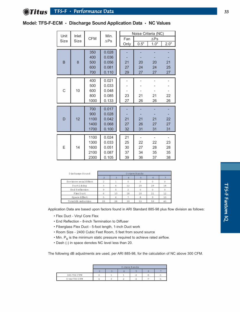
Model: TFS-F-ECM • Discharge Sound Application Data • NC Values
Fan
Only 0.5" 1.0" 2.0"
350 0.028 - - - -
400 0.036 - - - -
B 8 500 0.056 21 20 20 21
600 0.081 27 24 24 25
700 0.110 29 27 27 27
400 0.021 - - - -
500 0.033 - - - -
C 10 600 0.048 - - - -
800 0.085 23 21 21 22
1000 0.133 27 26 26 26
700 0.017 - - - -
900 0.028 - - - -
D 12 1100 0.042 21 21 21 22
1400 0.068 27 26 27 27
1700 0.100 32 31 31 31
1100 0.024 21 - - -
1300 0.033 25 22 22 23
E 14 1600 0.051 30 27 28 28
2100 0.087 37 34 35 35
2300 0.105 39 36 37 38
Noise Criteria (NC)
∆PsUnit
Size
Inlet
SizeCFM
Min.
∆Ps
Discharge Sound O ctave Bands
2 3 4 5 6 7
Environm ental Effect 2 1 0 0 0 0
Duct Lining 3 6 12 25 29 18
End Reflection 9 5 2 0 0 0
Flex Duct 6 10 18 20 21 12
Space Effect 5 6 7 8 9 10
Total dB reduction 25 28 39 53 59 40
Application Data are based upon factors found in ARI Standard 885-98 plus flow division as follows:
• Flex Duct - Vinyl Core Flex
• End Reflection - 8-inch Termination to Diffuser
• Fiberglass Flex Duct - 5-foot length, 1-inch Duct work
• Room Size - 2400 Cubic Feet Room, 5 feet from sound source
• Min. Ps is the minimum static pressure required to achieve rated airflow.
• Dash (-) in space denotes NC level less than 20.
The following dB adjustments are used, per ARI 885-98, for the calculation of NC above 300 CFM.
O ctave Bands
2 3 4 5 6 7
300-700 CFM 2 1 1 -2 -5 -1
O ver 700 CFM 4 3 2 -2 -7 -1

TTFFSS
--FF FF
aannttoo
mm IIQQ
3344 TTFFSS--FF •• PPeerrffoorrmmaannccee DDaattaa
Fan Plus 100% Primary
CFM Sound Power Octave Bands
2 3 4 5 6 7 2 3 4 5 6 7 2 3 4 5 6 7 2 3 4 5 6 7
350 58 48 45 39 32 27 54 45 42 39 35 31 56 48 44 40 39 37 58 51 45 42 42 44
400 59 49 46 40 36 31 57 47 44 40 37 32 58 50 45 42 40 39 60 53 47 43 44 46
B 500 62 51 48 43 42 38 60 50 47 42 39 34 62 54 48 44 43 41 64 57 49 46 46 48
600 64 53 49 45 46 43 63 53 49 45 41 36 65 56 51 46 44 43 66 60 52 48 48 49
700 65 54 51 46 51 48 65 56 51 46 43 37 67 59 53 48 46 44 69 62 54 50 50 51
400 47 41 40 32 27 23 50 43 40 35 32 27 52 47 42 37 36 35 55 51 44 40 41 42
500 51 44 43 36 31 27 52 45 42 38 34 29 55 49 44 40 38 36 58 53 46 42 42 44
C 600 54 47 46 40 35 30 54 46 44 40 35 30 57 50 46 42 40 38 60 54 48 44 44 45
800 60 52 50 45 40 35 58 49 47 43 38 33 61 53 49 45 42 40 64 57 51 47 46 48
1000 64 56 54 49 44 38 60 51 50 45 39 34 63 55 52 47 44 42 66 59 54 49 48 49
700 53 44 40 38 32 25 55 45 42 39 35 31 58 48 44 41 38 36 62 51 45 43 41 42
900 58 48 44 41 36 31 57 48 45 42 38 34 61 51 47 44 41 39 64 54 49 45 44 44
D 1100 61 52 47 44 39 35 60 51 48 44 40 36 63 54 49 46 43 41 67 57 51 47 46 47
1400 65 56 51 47 43 40 62 54 51 47 43 39 66 57 53 48 46 44 69 60 54 50 49 50
1700 68 59 54 49 46 44 65 56 53 49 45 41 68 60 55 50 48 46 72 63 57 52 51 52
1100 61 53 48 44 38 32 59 52 49 44 40 36 61 54 50 45 43 41 63 57 52 47 45 45
1300 65 56 52 47 42 37 62 55 51 46 43 39 64 57 53 48 45 43 66 59 54 49 48 47
E 1600 69 61 56 51 47 43 66 58 55 50 46 41 68 60 56 51 48 46 70 63 57 52 51 50
1900 73 66 61 56 52 49 70 62 58 53 49 45 72 64 60 55 51 49 74 66 61 56 54 53
2300 76 69 64 58 55 53 72 64 60 55 51 46 75 66 62 57 53 51 77 69 63 58 56 55
Unit
Size
Inlet
Size
Fan Only
0.5" ∆Ps
12
14
1.0" ∆Ps 2.0" ∆Ps
8
10
Model: TFS-F-ECM • Radiated Sound Power Data
• N/A in a space denotes a minimum inlet static pressure greater than 0.5 inch at rated airflow.
• Outlet ∆Ps, the difference in static pressure from the terminal discharge to the room, is 0.25 inch.
• Radiated sound power is the noise transmitted through the casing walls.
• Sound power levels are in decibels, re 10-12 watts.
• Ratings in accordance with ARI Standard 880 and certified to ARI.
Fan Inlet Prim. Fan Min
Size Size CFM CFM Ps 2 3 4 5 6 7 2 3 4 5 6 7
B 8 700 700 210 0.11 65 54 51 46 51 48 68 61 53 49 48 48
C 10 1050 1050 280 0.15 65 57 55 50 45 39 66 58 53 49 46 47
D 12 1600 1600 370 0.09 67 58 53 48 45 43 71 62 55 51 49 49
E 14 2100 2100 580 0.09 74 67 62 57 53 50 74 66 61 56 53 52
Fan Plus Primary @ 1.5" InletFan
Watts
Fan Only Sound Power
VA
RIA
BLE
AIR
VO
LU
ME
A ParticipatingCorporation
in the ARI 880Certification Program
ARI Certification Points

TTFFSS--FF FFaannttoomm
IIQQ3355TTFFSS--FF •• PPeerrffoorrmmaannccee DDaattaa
Model: TFS-F-ECM • Discharge Sound Power Data
Fan Plus 100% Primary
CFM Sound Power Octave Bands
2 3 4 5 6 7 2 3 4 5 6 7 2 3 4 5 6 7 2 3 4 5 6 7
350 60 53 52 52 51 49 58 51 51 51 50 49 59 52 51 51 50 49 60 53 51 51 51 49
400 63 56 54 55 54 52 60 54 53 53 53 51 62 55 53 54 53 52 63 55 53 54 53 52
B 500 68 61 58 59 59 58 65 59 57 57 57 56 66 59 57 57 57 56 67 60 57 58 58 57
600 72 65 61 63 63 62 69 63 59 60 61 60 70 63 60 61 61 60 71 64 60 61 61 61
700 76 68 64 66 66 65 72 66 62 63 64 63 73 67 62 63 64 63 75 67 62 63 64 64
400 61 55 51 52 51 47 57 50 48 46 45 42 59 51 47 46 45 42 60 51 47 46 45 42
500 64 57 54 55 54 51 60 53 51 50 49 47 61 53 50 50 49 47 62 54 50 50 49 47
C 600 66 60 55 57 56 54 61 55 53 53 52 51 63 56 53 53 52 51 64 56 53 53 53 51
800 69 63 58 60 60 59 64 59 57 58 58 57 65 59 57 58 58 58 67 60 57 58 58 58
1000 72 65 61 63 63 63 66 62 60 62 62 62 67 62 60 62 62 63 69 63 60 62 62 63
700 55 49 48 51 50 46 56 49 51 51 49 47 58 51 51 51 50 48 60 52 52 51 50 48
900 61 55 53 56 55 52 60 54 55 56 54 53 62 55 55 56 55 53 64 56 55 56 55 53
D 1100 65 49 57 60 59 58 63 57 58 60 58 57 65 58 58 60 59 58 67 59 58 60 59 58
1400 70 65 62 65 64 64 67 61 62 64 63 63 68 62 62 64 63 63 70 63 62 64 64 63
1700 74 69 65 68 69 69 69 64 65 68 67 67 71 66 65 67 67 67 73 67 65 68 68 68
1100 68 63 57 61 61 57 63 60 55 57 57 54 64 61 55 57 58 54 66 62 56 58 58 55
1300 71 67 60 64 64 62 66 63 58 60 61 58 67 64 58 61 61 59 69 65 59 62 62 59
E 1600 75 72 65 68 69 67 70 68 62 65 66 63 71 69 63 66 66 64 72 70 63 66 67 65
2100 80 78 70 74 75 73 74 74 68 71 72 71 76 75 68 71 72 71 77 76 68 72 73 72
2300 81 80 72 75 77 76 76 76 69 73 74 73 77 77 70 73 74 74 79 78 70 74 75 74
Unit
Size
Inlet
Size
Fan Only
0.5" ∆Ps
12
14
1.0" ∆Ps 2.0" ∆Ps
8
10
• N/A in a space denotes a minimum inlet static pressure greater than 0.5-inch at rated airflow.
• Outlet ∆Ps, the difference in static pressure from the terminal discharge to the room, is 0.25-inch.
• Discharge sound power is the noise emitted from the unit discharge into the downstream duct.
• Sound power levels are in decibels, re 10-12 watts.
• Ratings in accordance with ARI Standard 880 and certified to ARI.
VA
RIA
BLE
AIR
VO
LU
ME
A ParticipatingCorporation
in the ARI 880Certification Program
Fan Inlet Rated Fan Min
Size Size CFM CFM Ps 2 3 4 5 6 7
B 8 700 700 210 0.110 76 68 64 66 66 65
C 10 1050 1050 270 0.147 72 66 61 63 64 64
D 12 1600 1600 390 0.089 73 68 64 67 67 67
E 14 2100 2100 490 0.087 80 78 70 74 75 73
Fan
Watts
Fan Only Sound Power
ARI Certification Points

3366 TTFFSS ,, TTFFSS--FF •• SSuuggggeesstteedd SSppeecciiffiiccaattiioonnss
SuggestedSpecifications
Series Flow Fan PoweredTerminals
Series Flow(Constant Volume)
Fan PoweredTerminals
TFS Basic Unit, QuietSee Section S for ControlSpecifications.
1. Furnish and install TITUS Model (P)(A)(D)TFS series flow fan powered terminals of the sizes and capacities shown on the plans. Space limitations shall be reviewed carefully to ensure that all terminals will fit the available space.
2.Terminals should be certified under the ARI Standard 880 Certification Program and carry the ARI Seal. Non-certified terminals may be submitted after testing at an independent testing laboratory under conditions selected by the engineer in full compliance with ARIStandard 880. These tests must be witnessed by the engineering consultant with all costs to be borneby the terminal manufacturer. Testing does not ensure acceptance.
3. The terminal shall be designed, built, and tested as a single unit including motor and fan assembly, primary air damper assembly, wateror electric heating coils, and accessories as shipped. Unit shall ship as a complete assembly requiring no field assembly (including accessories). All electricalcomponents shall be UL listed and installed in accordance with the ULStandard 1995. Electrical connection shall be single point. All electrical components, including lowvoltage controls, shall be mounted in sheet metal control enclosures. The entire terminal shall be ETLlisted as a complete assembly.
4. The terminal casing shall be minimum 20-gauge galvanized steel, internally lined with ½-inch matte faced, natural fiber insulation that complies with UL 181 and NFPA 90A. The liner shall comply with ASTM G21 and G22 for fungi and bacterial resistance. The casingshall be designed for hanging by sheet metal brackets. The terminal shall have a round duct collar for the primary air connection and a centered rectangular discharge suitable for flanged duct connection.
5. The terminal casing shall have top and bottom access panels, which allows removal of fan assembly andservicing of terminal without disturbing duct connections.
6. The fan shall be constructed of steel and have a forward curved, dynamically balanced wheel with direct drive motor. The motor shall be suitable for 120, 208, 240, or 277 volt, 60 cycle, single-phase power. The motor shall be of energyefficient design, permanent split capacitor type, with integral thermal overload protection and permanently lubricated bearings, and be specifically designed for usewith an SCR for fan speed adjustment. Fan assembly shall include a tuned spring steel suspension and isolation between motor and fan housing.
7. The terminals shall utilize a manual SCR, which allows continuously adjustable fan speed from maximumto minimum, as a means of setting fan airflow. Setting fan airflow with any device that raises the pressure across the fan to reduce airflow is not acceptable. The speed control shall incorporate a minimum voltagestop to ensure that the motor cannot operate in a stall mode.
8. The primary air damper assembly shall be heavy gauge steel with shaft rotating in Delrin self-lubricating bearings. Nylon bearingsare not acceptable. Shaft shall be clearly marked on the end to indicate damper position. Stickers orother removable markings are not acceptable. The damper shall incorporate a mechanical stop to prevent overstroking, and a synthetic seal to limit close-off leakage to the maximum values shown in the following table. Provide an AeroCross™ four point, center-averaging differential pressure airflow sensor. A sensor that delivers the differential pressuresignal from one end of the sensor isnot acceptable. Balancing taps and airflow calibration charts shall be provided for field airflow measurements.
Maximum Damper Leakage
Inlet SizeDamper Leakage, CFM
1.5” ∆∆Ps 3.0” ∆∆Ps 6.0” ∆∆Ps
6 4 5 7
8 4 5 7
10 4 5 7
12 4 5 7
14 4 6 8
16 5 7 9
TTFFSS
,, TTFFSS
--FF FF
aannttoo
mm IIQQ

3377
Maximum Radiated Sound Power Level
Maximum Discharge Sound PowerLevel
9. The sound levels shall not exceedthe octave band sound power levelsindicated in the table above. Soundperformance shall be ARI certified. IfNC is provided instead of octaveband sound power data, the radiatedand discharge path attenuationfunction for the specified NC shall bebased upon factors found in ARIStandard 885-98, Appendix E. Noadditional attenuation factors shall bededucted from the sound power.
TFS-F Fantom IQTM
(Substitute paragraphs 1, 5 and 9 belowfor paragraphs 1 and 5 in the TFS BasicUnit Specification)
1. Furnish and install TITUS Model (P)(A)(D)TFS-F Fantom IQ series flow fan powered terminals of the sizes and capacities shown on the plans. Space limitations shall be reviewed carefully to ensure that all terminals will fit the available space.
5. The terminal casing shall have two top and two bottom access panels, which allows removal of fan assembly and servicing of terminal without disturbing duct connections. The terminal shall have internal and external attenuators factory installed. The external attenuator shall be shipped internal to the unit to protect it from shipping damage. The external attenuator shall be slid into the operation position and secured without the need for additional screws. Factory provided attenuators that require field installation are not acceptable.
TTFFSS ,, TTFFSS--FF •• SSuuggggeesstteedd SSppeecciiffiiccaattiioonnss
SuggestedSpecifications(continued)
Radiated Sound Octave Bands
2 3 4 5 6 7
Environmental Effect 2 1 0 0 0 0
Ceiling/Space Effect 16 18 20 26 31 36
Total dB reduction 18 19 20 26 31 36
Discharge Sound Octave Bands
2 3 4 5 6 7
Environmental Effect 2 1 0 0 0 0
Duct Lining 3 6 12 25 29 18
End Reflection 9 5 2 0 0 0
Flex Duct 6 10 18 20 21 12
Space Effect 5 6 7 8 9 10
Total dB reduction 25 28 39 53 59 40
The following dB adjustments are used, per ARI 885-98, for the calculation of NC above 300 CFM.
Octave Bands
2 3 4 5 6 7
300-700 CFM 2 1 1 -2 -5 -1
Over 700 CFM 4 3 2 -2 -7 -1
RadiatedOctave Band
2 3 4 5 6 7
NC35 70 61 54 53 52 51
NC40 74 68 61 59 58 57
DischargeOctave Band
2 3 4 5 6 7
NC35 80 77 69 73 74 73
NC40 84 80 72 75 75 74
TTFFSS,, TT
FFSS--FF FFaannttoomm IIQQ
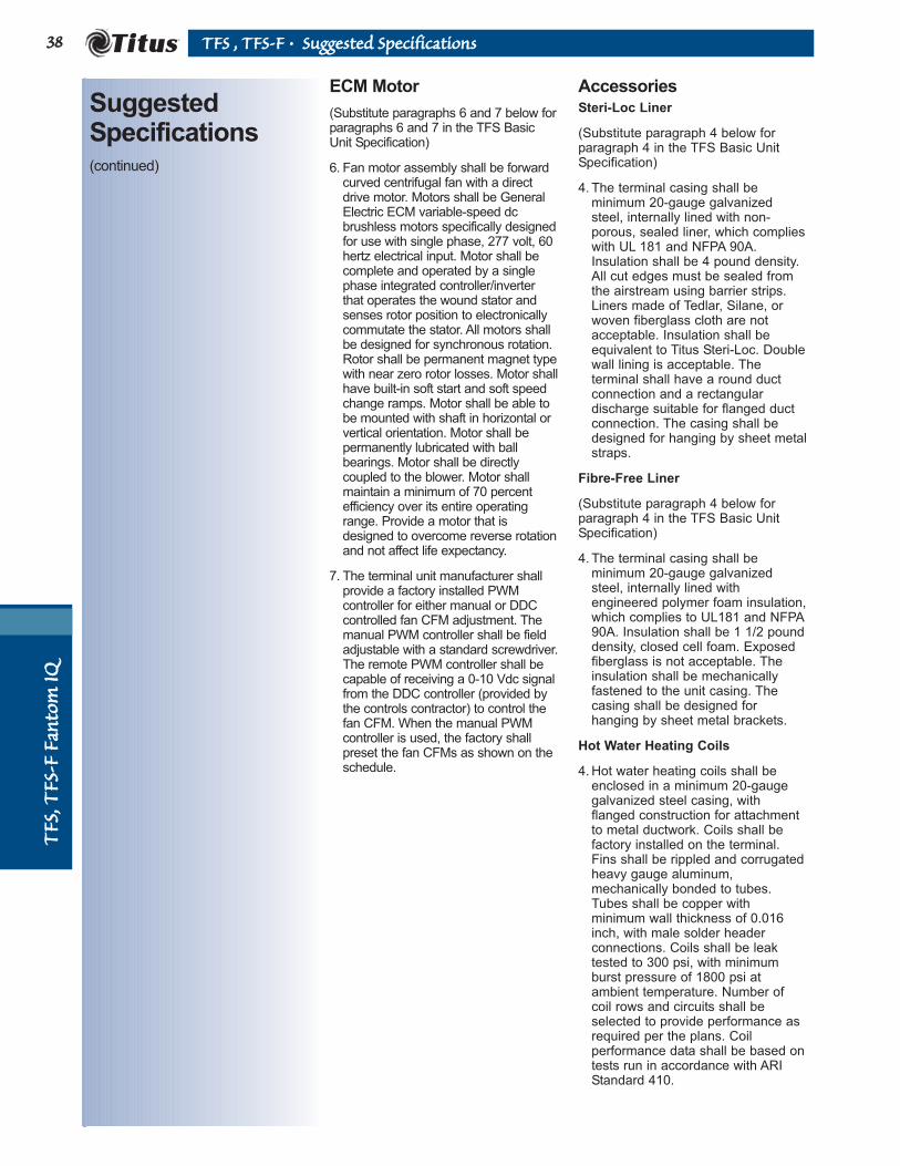
3388TT
FFSS,, TT
FFSS--FF
FFaann
ttoomm
IIQQ
ECM Motor
(Substitute paragraphs 6 and 7 below forparagraphs 6 and 7 in the TFS BasicUnit Specification)
6. Fan motor assembly shall be forward curved centrifugal fan with a direct drive motor. Motors shall be General Electric ECM variable-speed dc brushless motors specifically designed for use with single phase, 277 volt, 60 hertz electrical input. Motor shall be complete and operated by a single phase integrated controller/inverter that operates the wound stator and senses rotor position to electronically commutate the stator. All motors shall be designed for synchronous rotation. Rotor shall be permanent magnet type with near zero rotor losses. Motor shallhave built-in soft start and soft speed change ramps. Motor shall be able to be mounted with shaft in horizontal or vertical orientation. Motor shall be permanently lubricated with ball bearings. Motor shall be directly coupled to the blower. Motor shall maintain a minimum of 70 percent efficiency over its entire operating range. Provide a motor that is designed to overcome reverse rotation and not affect life expectancy.
7. The terminal unit manufacturer shall provide a factory installed PWM controller for either manual or DDC controlled fan CFM adjustment. The manual PWM controller shall be field adjustable with a standard screwdriver.The remote PWM controller shall be capable of receiving a 0-10 Vdc signal from the DDC controller (provided by the controls contractor) to control the fan CFM. When the manual PWM controller is used, the factory shall preset the fan CFMs as shown on the schedule.
AccessoriesSteri-Loc Liner
(Substitute paragraph 4 below forparagraph 4 in the TFS Basic UnitSpecification)
4. The terminal casing shall be minimum 20-gauge galvanized steel, internally lined with non-porous, sealed liner, which complies with UL 181 and NFPA 90A. Insulation shall be 4 pound density. All cut edges must be sealed from the airstream using barrier strips. Liners made of Tedlar, Silane, or woven fiberglass cloth are not acceptable. Insulation shall be equivalent to Titus Steri-Loc. Double wall lining is acceptable. The terminal shall have a round duct connection and a rectangular discharge suitable for flanged duct connection. The casing shall be designed for hanging by sheet metalstraps.
Fibre-Free Liner
(Substitute paragraph 4 below forparagraph 4 in the TFS Basic UnitSpecification)
4. The terminal casing shall be minimum 20-gauge galvanized steel, internally lined with engineered polymer foam insulation,which complies to UL181 and NFPA90A. Insulation shall be 1 1/2 pound density, closed cell foam. Exposed fiberglass is not acceptable. The insulation shall be mechanically fastened to the unit casing. The casing shall be designed for hanging by sheet metal brackets.
Hot Water Heating Coils
4. Hot water heating coils shall be enclosed in a minimum 20-gauge galvanized steel casing, with flanged construction for attachment to metal ductwork. Coils shall be factory installed on the terminal. Fins shall be rippled and corrugated heavy gauge aluminum, mechanically bonded to tubes. Tubes shall be copper with minimum wall thickness of 0.016 inch, with male solder header connections. Coils shall be leak tested to 300 psi, with minimum burst pressure of 1800 psi at ambient temperature. Number of coil rows and circuits shall be selected to provide performance as required per the plans. Coil performance data shall be based on tests run in accordance with ARI Standard 410.
TTFFSS ,, TTFFSS--FF •• SSuuggggeesstteedd SSppeecciiffiiccaattiioonnss
SuggestedSpecifications(continued)

3399TTFFSS ,, TTFFSS--FF •• SSuuggggeesstteedd SSppeecciiffiiccaattiioonnss
✕ ✕✕✕✕
P Pneumatic
A Analog Electronic
D Digital Electronic
Casing Configuration
20 Gauge
Unit and
Inlet Size
Specify
Lining Type
J EnviroLoc 1/2”
1 1"
2 SteriLoc
3 Foil Face
9 Fibre-Free
0 1/2” Fiberglass
K EnviroLoc 1”
Model Number Specification
Example: PTFS-F C 1 2 410
Pneumatically controlled quiet Series Flow fan terminal, with multi-point
sensor, 1-inch lining, 20-gauge casing; size C fan with 10-inch inlet.
3
AeroCross
Multi-Point Sensor
✕✕✕
Model
TFS Base
TFS-F Fantom IQ
2
SuggestedSpecifications(continued)
Accessories, continued.
Electric Heating Coils
1. Electric coils shall be supplied and installed on the terminal by the terminal manufacturer. Coil shall be integral with the terminal. Elements shall be 80/20 nickel chrome, supported by ceramic isolators a maximum of 3.5 inches apart, staggered for maximum thermal transfer and element life, and balanced to ensure equal output per step. The integral control panel shall be housed in a NEMA 1 enclosure, with hinged access door for access to all controls and safety devices.
2. Electric coils shall contain a primary automatic reset thermal cutout, a secondary replaceable heat limiter per element, differential pressure airflow switch for proof of flow, and line terminal block. Coil shall include an integral door interlock type disconnect switch, which will not allow the access door to be opened while power is on. Non-interlocking type disconnects are not acceptable. All individual components shall be UL listed or recognized.
3. (Optional) Electric coils shall include(manual reset secondary thermalcutouts), (line fusing), (mercurycontactors) mounted and wired withinthe control enclosure.
TTFFSS,, TT
FFSS--FF FFaannttoomm IIQQ

990 SECURITY ROW
RICHARDSON, TEXAS 75081
972-699-1030
FAX: 972-680-1971
E-MAIL: [email protected]
WWW.TITUS-HVAC.COM
COPYRIGHT ©2004 ALL RIGHTS RESERVED
FOR MORE INFORMATION, CONTACT:
REPRESENTED BY: