b avd.. b var.. - helios select...2.0 garantieansprüche – haftungsausschluss alle ausführungen...
TRANSCRIPT

Helios Brandgasventilatoren
B AVD.. B VAR..
in Temperaturklassen F300, F400, F600
D
Helios VentilatorenMONTAGE- UND BETRIEBSVORSCHRIFT NR. 85573
B AVD¬¬¬

Inhaltsverzeichnis
KAPITEL 1. SICHERHEIT . . . . . . . . . . . . . . . . . . . . . . . . . . . . . . . . . . . . . . . . . . . . . . . . . . . . . . . . . . . . . . . . . . . Seite 11.0 Wichtige Informationen . . . . . . . . . . . . . . . . . . . . . . . . . . . . . . . . . . . . . . . . . . . . . . . . . . . . . . . . . . . . . . . . . . Seite 11.1 Warnhinweise . . . . . . . . . . . . . . . . . . . . . . . . . . . . . . . . . . . . . . . . . . . . . . . . . . . . . . . . . . . . . . . . . . . . . . . . . Seite 11.2 Sicherheitshinweise . . . . . . . . . . . . . . . . . . . . . . . . . . . . . . . . . . . . . . . . . . . . . . . . . . . . . . . . . . . . . . . . . . . . Seite 11.3 Einsatzbereich . . . . . . . . . . . . . . . . . . . . . . . . . . . . . . . . . . . . . . . . . . . . . . . . . . . . . . . . . . . . . . . . . . . . . . . . Seite 21.4 Grenzen . . . . . . . . . . . . . . . . . . . . . . . . . . . . . . . . . . . . . . . . . . . . . . . . . . . . . . . . . . . . . . . . . . . . . . . . . . . . . Seite 31.5 Berührungsschutz . . . . . . . . . . . . . . . . . . . . . . . . . . . . . . . . . . . . . . . . . . . . . . . . . . . . . . . . . . . . . . . . . . . . . Seite 31.6 Personalqualifikation . . . . . . . . . . . . . . . . . . . . . . . . . . . . . . . . . . . . . . . . . . . . . . . . . . . . . . . . . . . . . . . . . . . . Seite 31.7 Förder- und Drehrichtung . . . . . . . . . . . . . . . . . . . . . . . . . . . . . . . . . . . . . . . . . . . . . . . . . . . . . . . . . . . . . . . . Seite 31.8 Drehzahlsteuerung . . . . . . . . . . . . . . . . . . . . . . . . . . . . . . . . . . . . . . . . . . . . . . . . . . . . . . . . . . . . . . . . . . . . . Seite 41.9 Funktionssicherheit – Notbetrieb . . . . . . . . . . . . . . . . . . . . . . . . . . . . . . . . . . . . . . . . . . . . . . . . . . . . . . . . . . Seite 4
KAPITEL 2. ALLGEMEINE HINWEISE . . . . . . . . . . . . . . . . . . . . . . . . . . . . . . . . . . . . . . . . . . . . . . . . . . . . . . . . . Seite 4 2.0 Garantieansprüche – Haftungsausschluss . . . . . . . . . . . . . . . . . . . . . . . . . . . . . . . . . . . . . . . . . . . . . . . . . . . Seite 42.1 Vorschriften – Richtlinien . . . . . . . . . . . . . . . . . . . . . . . . . . . . . . . . . . . . . . . . . . . . . . . . . . . . . . . . . . . . . . . . Seite 42.2 Transport . . . . . . . . . . . . . . . . . . . . . . . . . . . . . . . . . . . . . . . . . . . . . . . . . . . . . . . . . . . . . . . . . . . . . . . . . . . . Seite 42.3 Sendungsannahme . . . . . . . . . . . . . . . . . . . . . . . . . . . . . . . . . . . . . . . . . . . . . . . . . . . . . . . . . . . . . . . . . . . . Seite 42.4 Einlagerung . . . . . . . . . . . . . . . . . . . . . . . . . . . . . . . . . . . . . . . . . . . . . . . . . . . . . . . . . . . . . . . . . . . . . . . . . . Seite 42.5 Brandgas Serienausführung . . . . . . . . . . . . . . . . . . . . . . . . . . . . . . . . . . . . . . . . . . . . . . . . . . . . . . . . . . . . . . Seite 42.6 Leistungsdaten . . . . . . . . . . . . . . . . . . . . . . . . . . . . . . . . . . . . . . . . . . . . . . . . . . . . . . . . . . . . . . . . . . . . . . . . Seite 42.7 Geräuschangaben . . . . . . . . . . . . . . . . . . . . . . . . . . . . . . . . . . . . . . . . . . . . . . . . . . . . . . . . . . . . . . . . . . . . . Seite 5
KAPITEL 3. MONTAGE . . . . . . . . . . . . . . . . . . . . . . . . . . . . . . . . . . . . . . . . . . . . . . . . . . . . . . . . . . . . . . . . . . . . . Seite 53.0 Konstruktiver Aufbau . . . . . . . . . . . . . . . . . . . . . . . . . . . . . . . . . . . . . . . . . . . . . . . . . . . . . . . . . . . . . . . . . . . Seite 53.1 Montage – Einbau . . . . . . . . . . . . . . . . . . . . . . . . . . . . . . . . . . . . . . . . . . . . . . . . . . . . . . . . . . . . . . . . . . . . . Seite 63.2 Zwangsbelüftung über Radial-Kühlluftgebläse bei F600-Typen . . . . . . . . . . . . . . . . . . . . . . . . . . . . . . . . . . . . Seite 73.3 Aufstellung im Brandraum mit Radial-Kühlluftgebläse . . . . . . . . . . . . . . . . . . . . . . . . . . . . . . . . . . . . . . . . . . . Seite 83.4 Ventilatoraufstellung im Freien . . . . . . . . . . . . . . . . . . . . . . . . . . . . . . . . . . . . . . . . . . . . . . . . . . . . . . . . . . . . Seite 83.5 Technische Daten – Radial-Kühlluftgebläse B-KLG... . . . . . . . . . . . . . . . . . . . . . . . . . . . . . . . . . . . . . . . . . . . Seite 93.6 Zweistufige und Parallel-Einheiten . . . . . . . . . . . . . . . . . . . . . . . . . . . . . . . . . . . . . . . . . . . . . . . . . . . . . . . . .Seite 103.7 Lager-Zustandsdiagnostik . . . . . . . . . . . . . . . . . . . . . . . . . . . . . . . . . . . . . . . . . . . . . . . . . . . . . . . . . . . . . . Seite 113.8 Mindestluftspalte bei Einhaltung der Werkstoffpaarungen . . . . . . . . . . . . . . . . . . . . . . . . . . . . . . . . . . . . . . . Seite 113.9 Maximal zulässige Schwingungsgrenzwerte gemäß ISO 14694 / ISO 10816-3 . . . . . . . . . . . . . . . . . . . . . . Seite 123.10 Schwerpunktlage . . . . . . . . . . . . . . . . . . . . . . . . . . . . . . . . . . . . . . . . . . . . . . . . . . . . . . . . . . . . . . . . . . . . . Seite 123.11 Empfohlene Anziehdrehmomente für Befestigungsschrauben . . . . . . . . . . . . . . . . . . . . . . . . . . . . . . . . . . . Seite 123.12 Elektrischer Anschluss . . . . . . . . . . . . . . . . . . . . . . . . . . . . . . . . . . . . . . . . . . . . . . . . . . . . . . . . . . . . . . . . . Seite 133.13 Inbetriebnahme . . . . . . . . . . . . . . . . . . . . . . . . . . . . . . . . . . . . . . . . . . . . . . . . . . . . . . . . . . . . . . . . . . . . . . Seite 133.14 Betrieb . . . . . . . . . . . . . . . . . . . . . . . . . . . . . . . . . . . . . . . . . . . . . . . . . . . . . . . . . . . . . . . . . . . . . . . . . . . . . Seite 13
KAPITEL 4. INSTANDHALTUNG UND WARTUNG . . . . . . . . . . . . . . . . . . . . . . . . . . . . . . . . . . . . . . . . . . . . . . . Seite 144.0 Instandhaltung und Wartung . . . . . . . . . . . . . . . . . . . . . . . . . . . . . . . . . . . . . . . . . . . . . . . . . . . . . . . . . . . . Seite 144.1 Reinigung . . . . . . . . . . . . . . . . . . . . . . . . . . . . . . . . . . . . . . . . . . . . . . . . . . . . . . . . . . . . . . . . . . . . . . . . . . . Seite 144.2 Hinweise – Störungsursachen . . . . . . . . . . . . . . . . . . . . . . . . . . . . . . . . . . . . . . . . . . . . . . . . . . . . . . . . . . . Seite 144.3 Ersatzteile . . . . . . . . . . . . . . . . . . . . . . . . . . . . . . . . . . . . . . . . . . . . . . . . . . . . . . . . . . . . . . . . . . . . . . . . . . . Seite 154.4 Stilllegen und Entsorgen . . . . . . . . . . . . . . . . . . . . . . . . . . . . . . . . . . . . . . . . . . . . . . . . . . . . . . . . . . . . . . . . Seite 16
KAPITEL 5. TECHNISCHE DATEN . . . . . . . . . . . . . . . . . . . . . . . . . . . . . . . . . . . . . . . . . . . . . . . . . . . . . . . . . . . Seite 165.0 Technische Daten . . . . . . . . . . . . . . . . . . . . . . . . . . . . . . . . . . . . . . . . . . . . . . . . . . . . . . . . . . . . . . . . . . . . . Seite 165.1 Typenschlüssel . . . . . . . . . . . . . . . . . . . . . . . . . . . . . . . . . . . . . . . . . . . . . . . . . . . . . . . . . . . . . . . . . . . . . . . Seite 175.2 Typenschild . . . . . . . . . . . . . . . . . . . . . . . . . . . . . . . . . . . . . . . . . . . . . . . . . . . . . . . . . . . . . . . . . . . . . . . . . Seite 175.3 Motortypenschild . . . . . . . . . . . . . . . . . . . . . . . . . . . . . . . . . . . . . . . . . . . . . . . . . . . . . . . . . . . . . . . . . . . . . Seite 17
KAPITEL 6. SCHALTPLAN-ÜBERSICHT . . . . . . . . . . . . . . . . . . . . . . . . . . . . . . . . . . . . . . . . . . . . . . . . . . . . . . . Seite 186.0 Schaltpläne . . . . . . . . . . . . . . . . . . . . . . . . . . . . . . . . . . . . . . . . . . . . . . . . . . . . . . . . . . . . . . . . . . . . . . . . . Seite 186.1 Prinzipplan (SS-1023) . . . . . . . . . . . . . . . . . . . . . . . . . . . . . . . . . . . . . . . . . . . . . . . . . . . . . . . . . . . . . . . . . . Seite 206.2 Prinzipplan für F600 (SS-1024) . . . . . . . . . . . . . . . . . . . . . . . . . . . . . . . . . . . . . . . . . . . . . . . . . . . . . . . . . . . Seite 21
KAPITEL 7. . . . . . . . . . . . . . . . . . . . . . . . . . . . . . . . . . . . . . . . . . . . . . . . . . . . . . . . . . . . . . . . . . . . . . . . . . . . . . . Seite 227.0 Inbetriebnahmeprotokoll . . . . . . . . . . . . . . . . . . . . . . . . . . . . . . . . . . . . . . . . . . . . . . . . . . . . . . . . . . . . . . . . Seite 227.1 Prüf- und Wartungsplan . . . . . . . . . . . . . . . . . . . . . . . . . . . . . . . . . . . . . . . . . . . . . . . . . . . . . . . . . . . . . . . . Seite 24
Erreichen der Lebensdauer, EntsorgungBauteile und Komponenten des Ventilators, die ihre Lebensdauer erreicht haben, z.B. durch Verschleiß, Korrosion, mechanische Belastung, Ermüdung und / oderdurch andere, nicht unmittelbar erkennbare Einwirkungen, sind nach erfolgter Demontage entsprechend den nationalen und internationalen Gesetzen und Vorschriftenfach- und sachgerecht zu entsorgen. Das Gleiche gilt auch für im Einsatz befindliche Hilfsstoffe wie Öle und Fette oder sonstige Stoffe.Die bewusste oder unbewusste Weiterverwendung verbrauchter Bauteile wie z.B. Laufräder, Wälzlager, Keilriemen, etc. kann zu einer Gefährdung von Personen, derUmwelt sowie von Maschinen und Anlagen führen. Die entsprechenden, vor Ort geltenden Betreibervorschriften sind zu beachten und anzuwenden.
DEUTSCH

� GEFAHR � WARNUNG
� VORSICHT
1
B AVD.. und B VAR.. – Brandgasventilatoren F300/F400/F600Montage- und Betriebsvorschrift
1.0 Wichtige InformationenZur Sicherstellung einer einwandfreien Funktion und zur eigenen Sicherheit sind alle nachstehenden Vorschriften genaudurchzulesen und zu beachten.Dieses Dokument ist Teil des Produktes und als solches zugänglich und dauerhaft aufzubewahren. Der Betreiber ist fürdie Einhaltung aller anlagenbezogenen Sicherheitsvorschriften verantwortlich.Die dem Gerät zugehörige Zulassung und Leistungserklärung ist zu beachten!
1.1 Warnhinweise Nebenstehende Symbole sind sicherheitstechnische Warnhinweise. ZurVermeidung jeglicher Gefahrensituation, müssen alle Sicherheitsvor-schriften bzw. Symbole unbedingt beachtet werden!
1.2 Sicherheitshinweise
l SchutzbrilleDient zum Schutz vor Augenverletzungen.
p GehörschutzDient zum Schutz vor allen Arten von Lärm.
r ArbeitschutzkleidungDient vorwiegend zum Schutz vor Erfassen durch bewegliche Teile.Keine Ringe, Ketten oder sonstigen Schmuck tragen.
n SchutzhandschuheSchutzhandschuhe dienen zum Schutz der Hände vor Reibung, Abschürfun-gen, Einstichen oder tieferen Verletzungen, sowie vor Berührung mit heißenOberflächen.
m SicherheitsschuheSicherheitsschuhe dienen zum Schutz vor schweren herabfallenden Teilenund verhindern Ausrutschen auf rutschigem Untergrund.
HaarnetzDas Haarnetz dient vorwiegend zum Schutz vor Erfassen von langen Haarendurch bewegliche Teile.
Für Einsatz, Anschluss und Betrieb bei Brandgasventilatoren gelten besondereBestimmungen; bei Zweifel ist Rückfrage erforderlich. Die Bundes- sowie regionale Brandschutzverordung ist zu beachten! Weitere Informationensind den einschlägigen Normen, Bundesgesetzen, Landesbauverordnungen sowie Sonderbauverordnungen zu entnehmen.
�Bei allen Arbeiten am Ventilator sind die allgemein gültigen Arbeits- schutz- und Unfallverhütungsvorschriften einzuhalten!
• Es muss sichergestellt werden, dass der Brandgasventilator im Entrauch-ungsfall bis zum elektromechanischen Ausfall betrieben wird. Vorhandene Drehzahlregelungen oder Motorschutzeinrichtungen sind zu überbrücken!
• Vor allen Wartungs- und Installationsarbeiten oder vor Öffnen des Anschlussraums ist das Gerät allpolig vom Netz zu trennen und gegen uner-wünschtes Wiedereinschalten zu sichern! Der elektrische Anschluss darf nur von einer autorisierten Elektrofachkraft entsprechend den nachstehenden Anschlussplänen ausgeführt werden!
• Ventilator bis zum Einbau nur verpackt bewegen!
KAPITEL 1
SICHERHEIT
D

2
B AVD.. und B VAR.. – Brandgasventilatoren F300/F400/F600Montage- und Betriebsvorschrift
• Brandgasventilator nur mit für das Gewicht geeigneten Transportmitteln bewegen, beim Transport Sicherheitsschuhe tragen!
• Beiliegende Transportskizze beachten!• Beim Auspacken des Geräts Handschuhe/Sicherheitsschuhe tragen.• Geeignete Tragkraft, - eigenschaften des Befestigungsuntergrunds sicher-
stellen und diesbezüglich geeignete Befestigungsmittel verwenden.• Der Einbaubereich muss so gestaltet werden, dass keine Personen durch
die heißen Gase gefährdet werden können.• Der Ausblasbereich von Ventilator und Motorkühlung muss frei von entzünd-
baren Materialien sein und darf für Personen nicht zugänglich sein.• Es ist zu prüfen ob die Einbausituation das Tragen von Gehörschutz erfordert.• Der Betreiber ist für die Einhaltung aller anlagenbezogenen Sicherheitsvor-
schriften verantwortlich!• Anormal häufiges Ein-/Ausschalten ist nicht zulässig.• Der Berührungsschutz für das Axial-Laufrad gemäß DIN EN 13857 ist sicher-
zustellen. • Es muss sichergestellt werden, dass kein Wasser in den Brandgasventilator
gelangt! • Zur Einhaltung der Betriebssicherheit ist eine regelmäßige Schwingungs-
kontrolle durchzuführen! Alternativ empfiehlt es sich eine bauseitige Schwingungsüberwachung zu installieren.Angaben und zulässige Schwingungsgrenzwerte nach ISO 14694 aus derTabelle auf Seite 12, Punkt 3.9 sind zu beachten.
• Der Planer und Betreiber muss eine leichte Zugänglichkeit für Inspektions- und Reinigungsarbeiten gewährleisten!
• Eine gleichmäßige Zuströmung und ein freier Ausblas sind zu gewährleisten.
1.3 Einsatzbereich– Bestimmungsgemäßer Einsatz: Betrieb innerhalb des Kennlinienfelds des jeweiligen Geräts (siehe Katalog). Vibrationen und eine Zunahme der Geräuschentwicklung weisen auf einen Betrieb außerhalb des Kennlinienfeldes hin.
Lüftungsbetrieb:Förderung normaler oder leicht staubhaltiger (Partikelgröße < 10 µm), wenig aggressiver und feuchter Luft, in gemäßig-tem Klima bei Temperaturen im Bereich von -20 °C bis +40 °C, bei stationärem Einbau des Ventilators.Entrauchungsbetrieb:Einmalige Förderung von Brandgasen Typ F300 - 300 °C, 2h; Typ F400 - 400 °C, 2h; Typ F600 - 600 °C, 2h geprüft nach DIN EN 12101-3.Typ F600 mit Zwangsbelüftung: Für ausreichende Nachströmöffnung der Kühlluft (max. 40 °C) und gesicherte Ab-führung der Fortluft (max. 250 °C).Aufstellung:Im Brandraum, außerhalb vom Brandraum, im Freien (geschützt vor Witterungseinflüssen) vertikale sowie horizontaleAufstellung möglich.
– Vernünftigerweise vorhersehbarer Fehlgebrauch: Die Ventilatoren sind nicht zum Betrieb unter erschwerten Bedingungen wie z.B. hohe Feuchtigkeit, aggressive Medien, längere Stillstandzeiten, starke Verschmutzung, übermäßige Beanspruchung durch klimatische, technische oder elektronische Einflüsse geeignet. Eine Verwendung in einer mobilen Einheit (z.B. Fahrzeuge, Flugzeuge, Schiffe, usw.) ist nicht vorgesehen.
– Missbräuchlicher, untersagter Einsatz: Aufstellung im Freien ohne wirksamen Wetterschutz oder im direkten Kontakt mit Wasser. Förderung von explosions-fähigen Gasgemischen/Medien. Aufstellung in einem/r explosionsgefährdeten Bereich/Atmosphäre. Betrieb ohnenormgerechte Schutzeinrichtungen (z.B. Schutzgitter). Förderung von Feststoffen oder Feststoffanteilen > 10 µm im Fördermedium sowie Flüssigkeiten. Förderung von abrasiven und/oder die Ventilatorwerkstoffe angreifende Medien. Förderung von fetthaltigen Fördermedien. Entrauchungsbetrieb mit Motorschutzeinrichtung oder Frequenzumrichter.
D

3
B AVD.. und B VAR.. – Brandgasventilatoren F300/F400/F600Montage- und Betriebsvorschrift
1.4 GrenzenRäumlich:Vor und hinter dem Ventilator ist eine gerade glatte Rohrstrecke von 2,5 x D vorzusehen. In jedem Fall ist am Anfang der Rohrstrecke auf der Saugseite des Ventilators eine Ansaugdüse vorzusehen Bei Verwendung am Anfang oder Ende einer Rohrleitung ist der Bereich ohne Rohr ebenfalls in gleicher Weise freizuhalten. Die Ausblasöffnung muss Bauteile aus brennbaren Baustoffen mindestens 1 m überragen oder von diesen – waagerecht gemessen – 1,5 mentfernt sein. Die Ausblasrichtung darf nicht in Richtung brennbarer Bauteile erfolgen! Das ausblasseitge Umfeld ist nicht für Personen zugänglich. Der Ventilator muss für Reinigungs- und Wartungszwecke leicht zugänglich sein, ins-besondere der Klemmenkasten.Schnittstelle Energieversorgung:Anschluss nur mit festverlegten Leitungen in Funktionserhalt, 3 Phasen + PE, ein Motorvollschutzgerät (im Entrauch-ungsfall zu überbrücken). Eine Möglichkeit zur allpoligen Trennung vom Versorgunsnetz ist zwingend erforderlich! Abhängig von den örtlichen Gegegenheiten, ist ein Revisionsschalter für die allpolige Trennung vom Netz erforderlich. Zeitlich:Lüftungsbetrieb:Die Motorlager sind nach 5 Jahren zu erneuern. Bei Verwendung einer Lager-Zustandsdiagnostik gelten abweichende Bestimmungen, siehe Prüf- und Wartungsplan.Entrauchungsbetrieb:Das Gerät muss nach erfolgtem Entrauchungsbetrieb entsorgt werden!
1.5 BerührungsschutzBeim Einbau sind die allgemein gültigen Arbeitsschutz- und Unfallverhütungsvorschriften einzuhalten!Der Betreiber ist für die Einhaltung verantwortlich!– Kontakt mit rotierenden Teilen muss verhindert werden. Es ist sicherzustellen, dass sich im Ansaugbereich keine
Personen, Textilien oder andere ansaugbare Stoffe, wie z.B. auch Kleidung von Personen, befinden.– In Abhängigkeit der Einbauverhältnisse kann ein Berührungsschutz erforderlich sein. Entsprechende Schutzgitter
sind als Zubehör lieferbar.– Ventilatoren, die durch ihre Einbauweise (z.B. Einbau in Lüftungskanäle oder geschlossene Aggregate) geschützt
sind, benötigen kein Schutzgitter, wenn die Anlage die gleiche Sicherheit bietet. Es wird darauf hingewiesen, dass der Betreiber für Nichteinhaltung der aktuellen Norm (DIN EN 13857) und für Unfälle infolge fehlender Schutzein-richtungen haftbar gemacht werden kann.
1.6 Personalqualifikation– Alle elektrischen Arbeiten sowie die Inbetriebnahme dürfen nur von Elektrofachkräften ausgeführt werden.– Installation, Wartung und Instandhaltung mit Ausnahme der elektrischen Arbeiten dürfen nur von Fachkräften (Bsp.:
Industriemechaniker, Mechatroniker, Schlosser oder Vergleichbar) ausgeführt werden.– Bei Reparaturen an Entrauchungsventilatoren, sind diese grundsätzlich an Helios zurückzusenden.
1.7 Förder- und Drehrichtung
� WARNUNGDurch vom Ventilator herausgeschleuderte Teile können Ihre Augen verletzt werden!Zur Drehrichtungskontrolle Schutzbrille tragen!
� WARNUNG– Das drehende Laufrad kann Ihre Finger/Arme abtrennen oder einziehen!– Betrieb nur mit montierten Sicherheitseinrichtungen!– Beschädigungsgefahr!– Keine Gegenstände in das rotierende Laufrad stecken!
Die Luftförderrichtung ist über den Motor blasend (siehe Luft- und Drehrichtungspfeile).Die richtige Drehrichtung ist – bei Blick von vorne auf das Laufrad – links gegen Uhrzeigersinn.
Drehrichtung darf nur nach Abschalten bzw. Austrudeln des Ventilators geprüft werden!
Drehstromtypen sind bei elektrischem Anschluss im Rechtsdrehfeld durch Vertauschen zweier Phasen für Linkslauf anzuschließen. Falsche Drehrichtung kann zur Überhitzung und fehlender Luftleistung führen!
D
� HINWEIS
Abb.1 Abb.2
B AVD¬¬¬
Förderrichtung
Förderrichtung
� WARNUNG
� WARNUNG
� WARNUNG
� ACHTUNG
l

4
B AVD.. und B VAR.. – Brandgasventilatoren F300/F400/F600Montage- und Betriebsvorschrift
1.8 Drehzahlsteuerung– Die 1-tourigen Baureihen B VAR.. und B AVD.. F300/F400/F600 sind mit Kaltleitern (PTC) ausgestattet und dürfen
im Lüftungsbetrieb mittels Frequenzumrichter mit allpolig wirksamen Sinusfilter (Helios FU-CS) betrieben werden. – Die Drehzahlregelung aller Baureihen ist ausschließlich im Lüftungsbetrieb und mit Frequenzumrichter mit allpolig
wirksamen Sinusfilter zulässig.– Der Entrauchungsventilator ist auf seiner Nenndrehzahl zu betreiben.– Die Drehzahlsteuerung muss im Entrauchungsfall überbrückt werden!
1.9 Funktionssicherheit – NotbetriebBei Einsatz des Ventilators in wichtiger versorgungstechnischer Funktion ist die Anlage so zu konzipieren, dass bei Ventilatorausfall automatisch ein Notbetrieb garantiert ist. Geeignete Lösungen sind z.B.: Parallelbetrieb von zwei leistungsschwächeren Geräten mit getrenntem Stromkreis, Standby-Ventilator, Alarmeinrichtungen und Notlüftungssy-steme.Zur Aufrechterhaltung der Entrauchungsfunktion ist eine zusätzliche Versorgung bei Netzausfall notwendig. Leitungen sind in Funktionserhalt auszuführen.
2.0 Garantieansprüche – HaftungsausschlussAlle Ausführungen dieser Dokumentation müssen beachtet werden, sonst entfällt die Gewährleistung. Gleiches gilt fürHaftungsansprüche an Helios. Der Gebrauch von Zubehörteilen, die nicht von Helios empfohlen oder angeboten wer-den, ist nicht statthaft. Eventuell auftretende Schäden unterliegen nicht der Gewährleistung. Veränderungen und Umbauten am Gerät sind nicht zulässig und führen zum Verlust der Konformität, jegliche Gewährleistung und Haftung ist in diesem Fall ausgeschlossen.
2.1 Vorschriften – RichtlinienBei ordnungsgemäßer Installation und bestimmungsgemäßem Betrieb entspricht das Gerät den zum Zeitpunkt seiner Herstellung gültigen Vorschriften und EU-Richtlinien.
2.2 TransportDer Ventilator ist werkseitig so verpackt, dass er gegen normale Transportbelastungen geschützt ist. Der Transport istsorgfältig durchzuführen. Es wird empfohlen den Ventilator in der Originalverpackung zu belassen. Zum Transport oderzur Montage muss der Ventilator am Gehäuse oder den vorgesehen Trageösen aufgenommen werden – Transportskizze beachten! Hierbei geeignetes Hebezeug und Befestigungsvorrichtungen verwenden. Gewichts-angaben sind aus der Tabelle Punkt 5.0 auf Seite 16 oder der Kennzeichnung am Gerät zu entnehmen.Ventilator nicht an Anschlussleitungen, Klemmenkasten oder Laufrad transportieren!Nicht unter der schwebenden Last aufhalten!
2.3 SendungsannahmeDie Sendung ist sofort bei Anlieferung auf Beschädigungen und Typenrichtigkeit zu prüfen. Falls Schäden vorliegen um-gehend Schadensmeldung unter Hinzuziehung des Transportunternehmens veranlassen. Bei nicht fristgerechter Reklamation gehen evtl. Ansprüche verloren.
2.4 EinlagerungBei Einlagerung über längeren Zeitraum sind zur Verhinderung schädlicher Einwirkungen folgende Maßnahmen zu treffen:Schutz des Motors durch trockene, luft- und staubdichte Verpackung (Kunststoffbeutel mit Trockenmittel und Feuchtigkeitsindikatoren). Der Lagerort muss erschütterungsfrei, wassergeschützt und frei von Temperaturschwankun-gen sein. Lagertemperatur -20 °C bis +60 °C, diese Grenzwerte dürfen nicht überschritten werden. Die Motorlager müssen in regelmäßigen Abständen gedreht werden (10 Umdrehungen pro Monat). Bei einer Lager-dauer über drei Monate bzw. Motorstillstand, muss vor Inbetriebnahme eine Überprüfung der Lager erfolgen. Dabei den geräuschlosen, freien Lauf des Rades prüfen. Nach 2 jähriger Lagerzeit sind die Motorlager auszutauschen.Bei Weiterversand (vor allem über längere Distanzen; z.B. Seeweg) ist zu prüfen, ob die Verpackung für Transportartund -weg geeignet ist. Schäden, deren Ursache in unsachgemäßem Transport, Einlagerung oder Inbetriebnahme liegen, sind nachweisbar und unterliegen nicht der Gewährleistung.
2.5 Brandgas-SerienausführungDiese Montage- und Betriebsvorschrift beschreibt die Helios-Brandgasventilatoren der Baureihe:
Verbindliche Informationen zu den einzelnen Ventilatortypen sind dem Typenschild zu entnehmen.
2.6 LeistungsdatenDas Motortypenschild gibt über die elektrischen Werte Aufschluss; diese müssen mit dem örtlichen Versorgungsnetz-betreiber abgestimmt sein. Die Ventilatorleistungen* wurden auf einem Prüfstand entsprechend DIN EN ISO 5801:2010-12 ermittelt; sie gelten für die Nenndrehzahl und Normalausführung unter Verwendung einer Einströmdüse, ohne Schutzgitter bei ungehinderter An- und Abströmung und einem druckseitigen Rohrstück mit 2,5 x Durchmesser Länge.Hiervon abweichende Ausführungen und ungünstige Einbau- und Betriebsbedingungen können zu einer Reduzierung der Förderleistung führen.
KAPITEL 2
ALLGEMEINE HINWEISE
Baureihe Temperaturklasse DurchmesserBrandgas-Axial-Niederdruckventilatoren
B AVD..F300 Ø 500-1250 mmF400 Ø 500-1250 mmF600 Ø 500-1250 mm
Baureihe Temperaturklasse DurchmesserBrandgas-Hochdruck-Rohrventilatoren
B VAR..F300 Ø 280-1000 mmF400 Ø 500-1000 mmF600 Ø 500-1000 mm
B AVD¬¬¬
� GEFAHR
D
� ACHTUNG

5
B AVD.. und B VAR.. – Brandgasventilatoren F300/F400/F600Montage- und Betriebsvorschrift
KAPITEL 3
MONTAGE
B AVD¬¬¬
2.7 GeräuschangabenDie Geräuschangaben* beziehen sich ebenfalls auf die vorstehend beschriebene Anordnung. Gehäusevariationen, ungünstige Betriebsbedingungen u.a.m. können zu einer Erhöhung der angegebenen Katalog-Werte führen. Angaben, die sich auf bestimmte Abstände (1, 2, 4 m) beziehen, gelten für Freifeldbedingungen. Der Schalldruckpegel kann im Einbaufall erheblich von der Katalogangabe abweichen, da er stark von den Einbaugegebenheiten, d.h. vom Absorptionsvermögen des Raumes, der Raumgröße u.a. Faktoren abhängig ist.
3.0 Konstruktiver Aufbau
Baureihe B VAR 280-1000 F300 / B VAR 500-1000 F400Der Brandgas-Hochdruck-Rohrventilator ist ein direktangetriebener Ventilator bei dem der Motor im Luftstrom sitzt. DieFörderrichtung ist über den Motor blasend. Der axiale Strömungsverlauf ermöglicht eine verlustarme, geradlinige Luftführung und sorgt für einen hohen Wirkungsgrad des Ventilators. Das Rohrgehäuse mit beidseitigen Flanschen, integriertem Leitapparat und Motorhalterung besteht aus verzinktem Stahlblech.Das Halbaxial-Laufrad mit acht räumlich gekrümmten Schaufeln besteht aus verzinktem Stahlblech bzw. B VARD280-315 F300 aus Aluminium. Die dynamische Auswuchtung erfolgt nach ISO 1940 T1, Klasse 6,3.Technische Daten: IEC-Drehstrom-Motoren, 400 Volt, 50 Hz, IP 55, Isolationsklasse H
Baureihe B VAR 500-1000 F600Wie oben, jedoch Motor gekapselt und zusätzliches Zuluft-Gebläse erforderlich.
Baureihe B AVD 500-1250 F300 / F400Der Brandgas-Axial-Niederdruckventilator ist ein direktgetriebener Ventilator bei dem der Motor im Luftstrom sitzt. DieFörderrichtung ist über den Motor blasend. Der axiale Strömungsverlauf ermöglicht eine verlustarme, geradlinigeLuftführung und sorgt für einen hohen Wirkungsgrad des Ventilators. Das Rohrgehäuse mit beidseitigen Flanschen und Motorhalterung besteht aus Stahlblech verzinkt.Das Hochleistungs-Laufrad mit neun profilierten Flügeln besteht aus Aluminium. Die dynamische Auswuchtung erfolgtnach ISO 1940 T1, Klasse 6,3.Technische Daten: IEC-Drehstrom-Motoren, 400 Volt, 50 Hz, IP 55, Isolationsklasse H
Baureihe B AVD 500-1250 F600Das Rohrgehäuse mit beidseitigen Flanschen, integriertem Leitapparat und Motorhalterung besteht aus Stahlblech verzinkt. Der Motor ist gekapselt und ein zusätzliches Zuluft Gebläse ist erforderlich. Das Hochleistungs-Laufradmit fünf profilierten Flügeln besteht aus Stahlblech verzinkt. Die dynamische Auswuchtung erfolgt nach ISO 1940 T1, Klasse 6,3.Technische Daten: IEC-Drehstrom-Motoren, 400 Volt, 50 Hz, IP 55, Isolationsklasse H
Übersicht: Brandgasventilator B VAR.. mit Zubehörteilen (Horizontal)
Ansaugdüse ASD-SGD
Rohrverschluss-klappe RVS
Gegenflansch FRSchutzgitter SG
Segeltuchstutzen STSB
Abb.3
Schwingungsdämpfer SDD..für Druckbelastung
Montagekonsole MK
Montagekonsole MK
Schwingungsdämpfer SDZ..für Zugbelastung
B VAR..Verlängerungsrohr VR (optional)- Erforderlich bei Motorüberstand
siehe Punkt 3.10
Rohrschalldämpfer RSD
D
* (Leistungs- u. Geräuschangaben aus den aktuell gültigen Helios Druckschriften und dem Internet)

6
B AVD.. und B VAR.. – Brandgasventilatoren F300/F400/F600Montage- und Betriebsvorschrift
Montagebeispiele – Vertikal F300/400: Brandgasventilator B VAR.. mit Zubehörteilen
3.1 Montage – Einbau � WARNUNG Der Ventilator kann beim Aufstellen kippen und Gliedmaßen quetschen! Transportskizze und Schwerpunkt beachten! Sicherheitsschuhe tragen.
Alle Vorschriften der Arbeitssicherheit, Aufstellbedingungen und Leistungserklärungen (DIBt-Anwendungszulassung) sind bei der Montage und dem Einbau zu beachten!
Die Entrauchungsventilatoren müssen so aufgestellt und installiert werden, dass eine Inspektion, Wartung und Instand-setzung einfach und sicher durchgeführt werden kann.
Aufstellbedingungen VA: Für „ vertikale Aufstellung” geeignetHA: Für „horizontale Aufstellung” geeignetLB: Für „Lüftungsbetrieb” -20 °C bis +40 °CIB: „ Im Brandraum” aufstellbar
Ventilator ohne Dämmschicht, die Kühlluftleitung ist innerhalb des zu entrauchenden Bereichs mit L120 DIN 4102-4 zu dämmen
AB (WG): „Außerhalb des Brandraums, wärmegedämmt”In ausreichend gelüfteten Räumen, Ventilator mit Dämmschicht F300 L60 bzw. F400 u. F600 L120 nach DIN 4102-4
IF: „ Im Freien” Ventilator ohne Dämmschicht, wenn sichergestellt ist, dass kein Niederschlag in den Entrauchungsventilator eindringen kann
ZB: „Zwangsbelüftung” über Kühlluftkanal Eintrittstemperatur der Kühlluft in die Motorkapselung max. 40 °C, Mindestkühlluft beachten (Montagezubehör: Radial-Kühlluftgebläse, Wetterschutzdach bauseitig).
Anschluss der Entrauchungsleitungen mit Montagezubehör:– SegeltuchstutzenFür den saug- und/oder druckseitigen Anschluss der Entrauchungsventilatoren an Entrauchungsleitungen sind Segel-tuchstutzen (elastische Gewebestutzen) STSB... F400 bzw. F600 zu verwenden. Bei der Montage der Segeltuchstutzenist darauf zu achten, dass die Einbaulücke von 145 mm eingehalten wird und so eine Belastung auf Zug bzw. aufStauchung vermieden wird. Die elastischen Verbinder nicht versetzt einmontieren. So wird verhindert, dass es zuLeistungsminderung und auch Geräuschentwicklung kommt.– VerlängerungsrohrBeim Einbau in Rohrstrecken ist darauf zu achten, dass vor und nach dem Ventilator eine ausreichend lange geradeRohrstrecke 2,5 x Durchmesser (z.B. mit Verlängerungsrohr VR...) vorgesehen wird, da sonst mit erheblichen Leist-ungsminderungen und Geräuscherhöhung zu rechnen ist.– SchwingungsdämpferZur Vermeidung von Schwingungsübertragungen wird die Verwendung von Stahlfeder-/Schwingungsdämpfern SDD 1F4-10 und SDZ 1F 4-9 empfohlen. Die Anordnungen der Schalldämpfer, Montagekonsolen und der Schwingungs-dämpfer sind aus Abb. 6 bis 9 und auch Abb.17 ersichtlich.
Abb.4 Abb.5
Verlängerungs-rohr VR
B VAR..
MontageringVertikal MRV..
Schwingungsdämpfer SDD..für Druckbelastung
Verlängerungs-rohr VR
B VAR..
Schwingungsdämpfer SDZ..für Zugbelastung
MontageringVertikal MRV..
� WARNUNG
D
nm

7
B AVD.. und B VAR.. – Brandgasventilatoren F300/F400/F600Montage- und Betriebsvorschrift
– RohrschalldämpferAbbildung 9: Rohreinbau mit saug- und druckseitigem Rohrschalldämpfer RSD... F400 mit Montagekonsolen MK. Dersaugseitige Rohrschalldämpfer muss am Eintritt, der druckseitige am Austritt zusammen mit einem Segeltuchstutzenmontiert werden. – RohrverschlussklappeSelbsttätige Rohrverschlussklappe RVS... F400 mit Federrückstellung:Horizontal in jede Richtung, vertikal mit Durchströmung nach oben einbaubar.
3.2 Zwangsbelüftung über Radial-Kühlluftgebläse bei F600-TypenDie Motorkühlung der Helios F600-Entrauchungsventilatoren erfolgt sowohl im Entrauchungs- als auch im Entlüftungs-betrieb über separate Radial-Kühlluftgebläse (Typen B KLG, Zubehör). Diese Kühlluftgebläse werden im Entlüftungs-betrieb durch Strömungswächter (Type SWE, Zubehör) überwacht.– LüftungsbetriebIm Lüftungsbetrieb ist das Kühlluftgebläse zeitgleich mit dem Entrauchungsventilator einzuschalten. Meldet der Luft-stromwächter eine Störung, so ist nicht mehr sichergestellt, dass der Entrauchungsventilator mit ausreichend Kühlluftversorgt wird. Um Schäden am Entrauchungsventilator zu vermeiden, muss dieser sofort abgeschaltet und eine Stör-meldung ausgegeben werden.– EntrauchungsbetriebIm Entrauchungsbetrieb ist das Kühlluftgebläse zeitgleich mit dem Entrauchungsventilator einzuschalten. Meldet derLuftstromwächter oder der Motorschutz des Entrauchungsventilators eine Störung, ist der Entrauchungsbetrieb den-noch nicht zu unterbrechen. Es muss eine Störmeldung ausgegeben werden. Der Entrauchungsventilator läuft bis zuelektromechanischen Zerstörung.
Segeltuch stutzenSTSB
VerlängerungsrohrVR
Ventilator B VAR
Schwingungsdämpfer Rohrleitung 2,5 x DMontagekonsole
Schutzgitter Gegenflansch FR
Ansaug düseASD-SGD
Abb.7
Abb.6
Ventilator B VAR
Segeltuch stutzenSTSB
SchwingungsdämpferSchutzgitter
Ansaug düseASD-SGD
VerlängerungsrohrVR
RohrleitungGegenflansch FR
Montagekonsole
Schwingungs dämpfer
Schwingungsdämpfer
STSBSegeltuch stutzen
STSB Verlängerungs-rohr VR
Segeltuch stutzenSTSB
Rohr-leitung
Rohr-leitung
Rohr-leitung
Ventilator B AVD
Ventilator B AVD
Montagekonsole
Verlängerungs-rohr VR
Abb.8
Abb.9Rohr-leitung
Segeltuch stutzenSTSB
Montagekonsole
SchalldämpferRSD
SchalldämpferRSD
B AVD¬¬¬
D

8
B AVD.. und B VAR.. – Brandgasventilatoren F300/F400/F600Montage- und Betriebsvorschrift
D 3.3 Aufstellung von F600 Entrauchungsventilator im Brandraum mit Radial-Kühlluftgebläse für Motorkühlung
– Aufstellbedingung ZB = Zwangsbelüftung (siehe Typenschild)Zur Sicherstellung der Motorkühlung bei den F600-Baureihen, sind separate Radial-Kühlluftgebläse (z.B. B KLG 500oder B KLG 1000) notwendiges Zubehör. Das Kühlluftgebläse ist außerhalb des Brandraumes (Rauchabschnitts) inausreichend gelüfteten Räumen oder wettergeschützt im Freien zu montieren. Die Zulufttemperatur von 40 °C darf hierbeinicht überschritten werden (Abb.10). Angaben zum Mindestkühlvolumenstrom der jeweiligen Brandgastypen, sieheAuswahltabellen Seite 9.
� GEFAHR – Die Austrittstemperatur von Kühlluft kann bis zu 250 °C betragen!
– Die Fortluft aus der Motorkapselung ist ins Freie oder in einen ausreichend belüfteten Raum zu führen!– Die Umgebung/Technikraum muss ausreichend belüftet sein!– Die Ausblasrichtung darf nicht in Richtung brennbarer Bauteile erfolgen.– Das ausblasseitige Umfeld ist nicht für Personen zugänglich!
Auch bei Betrieb des F600-Entrauchungsventilators zu lüftungszwecken, ist eine Motorkühlung durch Radial-Kühlluft-gebläse zwingend erforderlich, da der Antriebsmotor in seiner Einhausung durch den Fördervolumenstrom desEntrauchungsventilators nicht gekühlt wird. Anderenfalls kommt es durch Überhitzung zum Ausfall des Antriebsmotors.
– KlemmenkastenWerkseitig ist der Klemmenkasten des F600-Entrauchungsventilators am Gehäuse montiert. Bei Aufstellung im Brand-raum (IB) ist der Klemmenkasten vom Gehäuse zu demontieren und außerhalb des Brandraums anzubringen (siehe Abb.10). Hierbei ist die Anschlussleitung vom Klemmenkasten zum Antriebsmotor (Leitungslänge ist bauseits anzupassen)durch den isolierten Kühlluftkanal zum Entrauchungsventilator zu führen.
3.4 Ventilatoraufstellung im FreienHelios Brandgas-Ventilatoren vom Typ B AVD... und B VARD... sind in der Einbauanordnung für horizontale oder verti-kale Luftförderrichtung für den Einsatz unter normalen Witterungsbedingungen im Freien geeignet. Das Eindringen vonNiederschlagswasser in den Brandgas-Ventilator ist zu verhindern.Besonders der Bereich der Ansaug- und Ausblasöffnungen ist durch den Anbau von Verlängerungsrohren (bei horizon-taler Luftförderrichtung) oder z.B. einer bauseitigen Wetterschutzhaube (Ende/Anfang einer Rohr/- Kanalstrecke bei ver-tikaler Luftförderrichtung) zu schützen.Durch eine geeignete Einbaulage (Öffnungen seitlich oder nach unten) sind Öffnungen im Ventilatorgehäuse vor demEindringen von Niederschlagswasser zu schützen. Hierbei ist besonders auf die Gehäusedurchführung der Zuleitungzwischen Gehäuseklemmenkasten und Motoranschluss, sowie die Ausblasöffnungen der Kühlluft aus der Motor-kapselung bei F600 Brandgas-Ventilatoren zu achten.Radial-Kühlluftgebläse für F600 Entrauchungsventilatoren sind durch bauseitige Schutzeinrichtungen (z.B. Wetter-schutzdach) vor Witterungseinflüssen zu schützen.Bei der Isolation von im Freien aufgestellten Brandgas-Ventilatoren, ist sicherzustellen, dass kein Niederschlagswasserin die Isolation eindringen kann (z.B. Wetterschutzdach).
Abb.10
Kühlluftleitung mit Wärmedämmungund Anschlussleitung vonKlemmenkasten
Umgebung/Technikraum (max. 40 °C mit Nachströmung)
¬Brandraum¬
� GEFAHR

9
B AVD.. und B VAR.. – Brandgasventilatoren F300/F400/F600Montage- und Betriebsvorschrift
D
Type Gebläse Kühlluftmenge Menge Gehäuse noch verfügbar
B VAR B KLG benötigt, V· [m3/h] Stück [Pa]1 Dpex [Pa]2
500 500 250 1 95 314
560 500 340 1 175 187
630 1000 445 1 80 129
710 1000 565 1 125 73
800 500 700 2 190 160
900 1000 850 2 70 140
1000 1000 1000 2 100 106
1120 - - - - -
1250 - - - - -
Radial-Kühlluftgebläsefür Brandgas-Ventilatoren F600 zur Motorbelüftung. BeiLüftungsbetrieb, ist ein Strömungswächter (Type SWE,Best.-Nr. 0065, Zubehör) zur Überwachung der Motor-kühlung erforderlich.
Technische DatenType B KLG 1000 Best.-Nr. 2799Schutzart IP44 Leistung 175 WattSpannung 400 Volt max. Umgebungstemperatur 40 °CFrequenz 50 Hz Drehzahl 1330 1/minStrom 0,39 Amp. Volumenstrom 1030 m3/hSchaltplan SS-1019
Maße in mm
Radial-Kühlluftgebläsemit separat herausgeführtem Thermokontakt für Brand-gasventilatoren F600 zur Motorbelüftung. Bei Lüftungs-betrieb, ist ein Strömungswächter (Type SWE, Best.-Nr.0065, Zubehör) zur Überwachung der Motorkühlung er-forderlich.Technische DatenType B KLG 500 Best.-Nr. 2798Schutzart IP44 Leistung 160 WattSpannung 230 Volt max. Umgebungstemperatur 40 °CFrequenz 50 Hz Drehzahl 2400 1/minStrom 0,7 Amp. Volumenstrom 500 m3/hSchaltplan SS-1018
Maße in mm
n=2400 1/min n=1330 1/minB KLG 500 B KLG 1000
Auswahltabelle – Kühlluftmenge für B VAR..
Kühllufttemperatur max. 40 °C 1 Widerstand im Ventilator/Kühlsystem 2 Verfügbarer Druck am Ausblas des Kühlluftgebläses
Kühllufttemperatur max. 40 °C 1 Widerstand im Ventilator/Kühlsystem 2 Verfügbarer Druck am Ausblas des Kühlluftgebläses
Auswahltabelle – Kühlluftmenge für B AVD..
Type Gebläse Kühlluftmenge Menge Gehäuse noch verfügbar
B AVD B KLG benötigt, V· [m3/h] Stück [Pa]1 Dpex [Pa]2
500 500 250 1 95 314
560 500 280 1 115 290
630 500 315 1 150 235
710 500 355 1 190 155
800 500 400 1 65 207
900 1000 450 1 80 129
1000 1000 500 1 100 106
1120 1000 875 2 75 135
1250 1000 1250 2 155 31
Type Ø F600 B AVD Maß A (mm) B VAR Maß A (mm)
500 626 626
560 626 626
630 626 696
710 626 696
800 626 626
900 696 696
1000 696 696
1120 696 -
1250 696 -
Auswahltabelle – Kühlluftgebläse B KLG..
Maße in mm
B KLG 1000
B KLG 500
Zuordnung, siehe nebenstehende Tabelle.
3.5 Technische Daten – Radial-Kühlluftgebläse B KLG...
Pa Pa
m3/hm3/h
Abb.11 Abb.12B KLG 500 B KLG 1000
Abb.13

D
10
B AVD.. und B VAR.. – Brandgasventilatoren F300/F400/F600Montage- und Betriebsvorschrift
3.6 Zweistufige und Parallel-EinheitenDie vielseitigen Anforderungen hinsichtlich Druckerhöhung, Förderleistung und Platzbedarf werden im Bereich derTechnischen Gebäudeausrüstung (TGA) häufig durch zwei stufige Z- oder parallele P-Einheiten erfüllt. Für die jeweiligeBauweise bietet das Helios Programm (siehe Verkaufsunterlagen) entsprechende Montagepakete an:
Abmessungen:
3.7 Lager-Zustandsdiagnostik Type: LZD-Basic und LZD-Comfort
Die Helios Lager-Zustandsdiagnostik dient der sichern Überwachung der Funktionsfähigkeit von Motorlagern imAntriebsmotor des Entrauchungsventilators. Das System ermöglicht wahlweise durch stetige oder gelegentlicheÜberwachung der Lagerzustände die frühzeitige Erkennung von sich anbahnenden Lagerschäden. Eine Auswechslungder Lager erfolgt nicht periodisch, sondern in Abhängigkeit des tatsächlichen Verschleißes. Hierzu ist der Prüf- undWartungsplan in dieser Montage- und Betriebsvorschrift zu beachten. Vor Betrieb und Einsatz der Lager-Zustands-diagnostik ist die separate MBV des Überwachungssystems zu beachten.
Angaben zu weiterem Brandgas-Zubehör sind aus dem Internet (www.heliosselect.de), Hauptkatalog bzw. den HeliosVerkaufsunterlagen zu entnehmen.
Zweistufige Bauweise / Montagepaket MP-ZZwei in Reihe geschaltete Ventilatoren (Abb.14) sorgen für konkurrenzlose Leistungsdichte und vor-teilhafte Installation durch geringsten Platzbedarf.Die beiden Ventilatoren werden hintereinander an-geordnet und mittels Verlängerungsrohren verbun-den.� Kein Montagering Vertikal möglich (MRV)
Lieferumfang:- Verlängerungsrohre (2 St.) inkl. Montagesatz
(Sechskantschrauben, -muttern, Federringe).
Parallel-Einheit / Montagepaket MP-PZwei parallel geschaltete Ventilatoren (Abb.15)bringen große Luftmengen bei entsprechenderDruck ziffer und erfüllen speziell die Ansprüche zurGaragen-Lüftung und -Entrauchung. Zwei identi-sche, nebeneinander angeordnete Ventilatoren arbeiten in einem gemeinsamen Kanalsys tem.Lieferumfang:- Verlängerungsrohre (2 St.),- Rohrverschlussklappen (2 St.),- Montagekonsolen (4 St.)- Montageschienen (2 St.)- Montagesätze (Sechskantschrauben, -muttern,
Federringe, Scheiben und Gewindeplatte).
MP-Z MP-P
Ø A B C D E A B C D E F G1) H I J
280 280 322 346 1200 8x Ø9,5 280 322 346 900 0 558 390-470 980 281 8x Ø9,5
315 315 356 380 1200 8x Ø9,5 315 356 380 900 0 548 420-520 1085 316,5 8x Ø9,5
355 355 395 420 1200 8x Ø9,5 355 395 420 900 0 548 460-580 1120 336 8x Ø9,5
400 400 438 465 1320/1360* 12x Ø9,5 400 438 465 990/1010*
0 607/626*
510-580 1120 346,5 12x Ø9,5
450 450 487 515 1360 12x Ø9,5 450 487 515 1010 10 626 560-650 1200 397 12x Ø9,5
500 500 541 565 1360/1690* 12x Ø9,5 500 541 565 1010 40 626 615-730 1500 445 12x Ø9,5
560 560 605 640 1840 16x Ø11,5 560 605 640 1250 65 865 700-820 1600 477 16x Ø11,5
630 630 674 710 1840 16x Ø11,5 630 674 710 1320 115 855 760-920 1700 527 16x Ø11,5
710 710 751 810 2140 16x Ø11,5 710 751 810 1470 155 995 860-1020 1900 639 16x Ø11,5
800 800 837 900 1980 24x Ø11,5 800 837 900 1410 200 914 950-1120 2000 689 24x Ø11,5
900 900 934 1000 2400 24x Ø11,5 900 934 1000 1410 250 914 1070-1240 2200 749 24x Ø11,5
1000 1000 1043 1100 2560 24x Ø11,5 1000 1043 1100 1490 300 994 1200-1370 2400 814 24x Ø11,5
Abb.14 Abb.15
* Zusätzliches Verlängerungsrohr 1) Abstand je nach Zubehör

11
B AVD.. und B VAR.. – Brandgasventilatoren F300/F400/F600Montage- und Betriebsvorschrift
D3.8 Mindestluftspalte bei Einhaltung der Werkstoffpaarungen
Laufrad von Hand bewegen um den Freilauf zu überprüfen!Vor dem Einbau den Mindestluftspalt (MLS) zwischen Laufradspitze und Gehäuse nach folgender Tabelle prüfen:
Entsprechen die festgestellten Werte nicht den Sollmaßen, darf der Ventilator nicht eingebaut bzw. betrieben werden. Bei Fragen, bitte den Helios Kundendienst „TGA” kontaktieren.Eigene Reparaturversuche sind strikt untersagt!
Type TK MLS (in mm) Type TK MLS (in mm)
B VAR.. 280 F300 2,0
B VAR.. 315 F300 2,0
B VAR.. 355 F300 2,5
B VAR.. 400 F300 2,5
B VAR.. 450 F300 2,5
B VAR.. 500 F300 2,5 B AVD.. 500 F300 4,5
B VAR.. 560 F300 3,0 B AVD.. 560 F300 4,6
B VAR.. 630 F300 3,0 B AVD.. 630 F300 5,2
B VAR.. 710 F300 3,5 B AVD.. 710 F300 5,7
B VAR.. 800 F300 4,0 B AVD.. 800 F300 5,8
B VAR.. 900 F300 4,5 B AVD.. 900 F300 6,9
B VAR.. 1000 F300 5,0 B AVD.. 1000 F300 7,0
B AVD.. 1120 F300 8,1
B AVD.. 1250 F300 8,8
B VAR.. 500 F400 4,6 B AVD.. 500 F400 5,6
B VAR.. 560 F400 5,1 B AVD.. 560 F400 6,2
B VAR.. 630 F400 5,8 B AVD.. 630 F400 7,0
B VAR.. 710 F400 6,5 B AVD.. 710 F400 7,9
B VAR.. 800 F400 7,3 B AVD.. 800 F400 8,9
B VAR.. 900 F400 8,2 B AVD.. 900 F400 10,0
B VAR.. 1000 F400 9,1 B AVD.. 1000 F400 11,1
B AVD.. 1120 F400 12,4
B AVD.. 1250 F400 13,9
B VAR.. 500 F600 7,0 B AVD.. 500 F600 6,0
B VAR.. 560 F600 8,0 B AVD.. 560 F600 6,0
B VAR.. 630 F600 10,0 B AVD.. 630 F600 7,0
B VAR.. 710 F600 10,0 B AVD.. 710 F600 7,0
B VAR.. 800 F600 11,0 B AVD.. 800 F600 8,0
B VAR.. 900 F600 12,5 B AVD.. 900 F600 9,0
B VAR.. 1000 F600 14,0 B AVD.. 1000 F600 11,0
B AVD.. 1120 F600 12,0
B AVD.. 1250 F600 13,0
Abb.16 � ACHTUNG
� VORSICHT

D
12
B AVD.. und B VAR.. – Brandgasventilatoren F300/F400/F600Montage- und Betriebsvorschrift
3.9 Maximal zulässige Schwingungsgrenzwerte gemäß ISO 14694 / ISO 10816-3
– Schwingungswächter Bei Verwendung von Schwingungswächtern dürfen diese den Brandgasventilator im Entrauchungsfall nicht abschalten!
– Installation eines Schwingungswächters Die Installation eines Schwingungswächters (bauseits), muss am Gehäuse des Ventilators erfolgen und darf nicht in der Drehbereichszone des Laufrads liegen. Der Luftspalt (siehe Abb.16) darf durch die Installation des Schwingungswächters nicht beeinflusst werden!
– Auswahl der Schwingungsdämpfer Um die von den rotierenden Bauteilen im Ventilator erzeugten Schwingungen optimal dämpfen zu können, ist dierichtige Auswahl der Schwingungsdämpfer entscheidend. Die Auslegung erfolgt anhand der ermittelten Gesamt-masse von Ventilator inkl. Anbauteilen, die zu dämpfen ist. Hierzu müssen die einzelnen Nettogewichte derKomponenten addiert werden.
Beispiel:B VAR 900/4 37 kW F300 als Z-Einheit1) Ermittlung der zu dämpfenden Masse
B VAR 900/4 533 kgB VAR 900/4 533 kgMP-Z 900 68 kgVR 900 34 kgMK 900 18 kgGesamtgewicht 1186 kg
3.10 SchwerpunktlageJe nach Baugröße und Motorleistung, ergibt sich ein Motorüberstand und somit eine unsymmetrische Schwerpunkts-lage außerhalb des Gehäuses. Zur Vermittlung des Schwerpunktes ist ein Verlängerungsrohr (Type VR..) zu verwenden(Abb.17). Die Gewichtsangaben der jeweiligen Typen sind dem Typenschild zu entnehmen!
3.11 Empfohlene Anzugsmomente für BefestigungsschraubenFolgende Anzugsmomente für Verbindungen von Befestigungsschrauben und -muttern (Festigkeitsklasse 8.8) sind zubenutzen:Die Laufradbefestigung auf der Motorwelle ist werkseitig mit flüssiger Schraubensicherung gegen Lösen gesichert.
max. zulässige Schwingungsgrenzwerte bei einer Lüfterleistung < 75 kW
Inbetriebnahme Alarm Abschalten
fest montiert flexibel aufgestellt fest montiert flexibel aufgestellt fest montiert flexibel aufgestellt
[mm/s] [mm/s] [mm/s] [mm/s] [mm/s] [mm/s]
4,5 6,3 7,1 11,8 9,0 12,5
Abb.17RICHTIG!
(Schwerpunkt)
FALSCH!
(Schwerpunkt)
Schraubengröße Anzugsmoment Anzugsmoment VERBUS RIPPM8 20 Nm 25 NmM10 35 Nm 49 NmM12 60 Nm 86 NmM16 150 Nm 210 Nm
� ACHTUNG
� ACHTUNG
� ACHTUNG

D
13
B AVD.. und B VAR.. – Brandgasventilatoren F300/F400/F600Montage- und Betriebsvorschrift
3.12 Elektrischer Anschluss
� WARNUNG Vor allen Wartungs- und Installationsarbeiten oder vor Öffnen des Anschlussraums ist das Gerät allpolig vom Netz zu trennen und gegen unerwünschtes Wiedereinschalten zu sichern!
– Der elektrische Anschluss darf nur von einer autorisierten Elektrofachkraft entsprechend den Angaben im Motor- klemmenkasten und den beiliegenden Anschlussplänen ausgeführt werden.– Die einschlägigen Normen, Sicherheitsbestimmungen (z. B. DIN VDE 0100) sowie die TAB der EVUs sind unbedingt zu beachten.– Die Angaben zu „Elektrische Leitungsanlagen” in der DIBt-Zulassung (Abschnitt 2.1.8) sind zu beachten.– Die Angaben zu „Auslöseeinrichtungen” in der DIBt-Zulassung (Abschnitt 2.1.9) sind zu beachten.– Der elektrische Anschluss muss so ausgeführt werden, dass der Ventilator im Entrauchungsfall bis zum elektro- mechanischen Ausfall, bei Nenndrehzahl betrieben wird. Hierfür ist jede Art von Drehzahlsteuerung, Motorschutz, Luftströmungswächter, Schwingungswächter, sowie der TK des Kühlluftgebläses bei F600 Geräten im Entrau- chungsfall zu überbrücken und darf nicht zur Abschaltung des Ventilators führen.– Anschlussdaten müssen mit den An gaben des Motorleistungsschildes übereinstimmen.– Die Einführung der Zuleitung ist fachgerecht auszuführen! Die Anschlussleitung in den Gehäuseklemmenkasten muss die event. auftretenden Schwingungen des Ventilators ausgleichen, besonders bei Einsatz von Schwingungsdämpfern. Leitung nie über scharfe Kanten führen!– Drehstromtypen sind im Rechtsdrehfeld durch Ver tauschen zweier Phasen für Linkslauf anzu schließen.– Sicherheitsbauteile, z.B. Schutzgitter, dürfen weder demontiert noch umgangen oder außer Funktion gesetzt werden.– Weitere Arbeitsgänge siehe nachfolgenden Abschnitt „ Inbe triebnahme“.– Erdverbindungen, einschließlich zusätzlicher Potentialausgleichanschlüsse sind ordnungsgemäß zu installieren!
3.13 Inbetriebnahme
� WARNUNG Das drehende Laufrad kann Ihre Finger quetschen. Vor der Inbetriebnahme Berührungsschutz sicherstellen!
Folgende Kontrollarbeiten sind vor der Erstinbetriebnahme auszuführen bzw. zu prüfen:– Die Transportsicherung muss vor der Funktionsprüfung entfernt werden!– Bestimmungsgemäßen Einsatz des Ventilators über prüfen– Zulässige Fördermitteltemperatur– Netzspannung mit Leistungsschildangabe vergleichen– Ventilator auf solide Befestigung und fachgerechte elektrische Installation prüfen– Alle Teile, insbesondere Schrauben, Muttern, Schutzgitter auf festen Sitz überprüfen. Schrauben dabei nicht lösen!– Freilauf des Laufrades– Mindestluftspalte laut Tabelle 3.8 prüfen – Sicherstellen, dass der Ansaug- und Ausblasbereich nicht für Personen zugänglich ist.– Übereinstimmung der Dreh- und Förder rich tung. Drehrichtung des Laufrades prüfen; durch kurzzeitiges
Einschalten; beim Prüfen der Drehrichtung eine Schutzbrille tragen!– Stromaufnahme mit Leistungsschildangabe vergleichen– Motorschutzeinrichtung auf Funktion testen– Schutzleiteranschluss prüfen– Abdichtung des Anschlusskabels in den Klemmenkasten und festen Klemm sitz der Adern prüfen– Inbetriebnahme darf nur erfolgen, wenn der Be rührungsschutz sichergestellt ist– Dichtheit aller Verbindungen prüfen (falls erforderlich)– Montagerückstände aus Ventilator bzw. Kanal entfernen– Beim Probelauf den Ventilator auf unzulässige Vibrationen und Geräusche prüfen– Den Ventilator nicht außerhalb der angegebenen Kennlinie (siehe Katalog / Internet) betreiben.
Der Ventilator muss auf seinem vorgeschriebenen Betriebspunkt laufen– Das beigelegte Inbetriebnahmeprotokoll (siehe Seite 22) ausfüllen und im Gewährleistungsfall vorlegen– Radial-Kühlluftgebläse B KLG... für F600-Typen überprüfen, Kühlluftmenge anhand des Druckverlustes aus den
Diagrammen in 3.5 prüfen.– Das beigelegte Inbetriebnahmeprotokoll ist dem Anlagenbetreiber ausgefüllt auszuhändigen
3.14 Betrieb Regelmäßig die einwandfreie Funktion des Ventilators prüfen:
– Freilauf des Laufrades– Prüfung des Luftspaltes (siehe Tabelle 3.8)– Messen der Stromaufnahme– Prüfung auf eventuelle Schwingungen und Geräusche– Ablagerungen von Staub und Schmutz im Gehäuse bzw. am Motor und Laufrad
Hinsichtlich Funktionserhalt und Verlegung der elektr. Leitungsanlagen gelten die einschlägigen Vorschriftendes VDE-Regelwerkes sowie die landesrechtlichen Vorschriften, insbesondere der "Richtlinie über brand-schutz technische Anforderungen an Leitungsanlagen". Der Ventilator muss während der vorgesehenenEntrauchungsdauer funktionsfähig bleiben (Funktionserhalt).
� WARNUNG
� WARNUNG
� ACHTUNG
� ACHTUNG
nmr
l
� ACHTUNG

D
4.0 Instandhaltung und Wartung
� WARNUNG Vor allen Wartungs- und Installationsarbeiten oder vor Öffnen des Anschlussraums ist das Gerät allpolig vom Netz zu trennen und gegen unerwünschtes Wiedereinschalten zu sichern!
– Übermäßige Ablagerungen von Schmutz, Staub, Fetten u.a.m. auf Laufrad, Motor, Schutzgitter und vor allem zwi- schen Gehäuse und Laufrad sind unzu lässig und durch periodische Reinigung zu unterbinden.– Eine Funktionsprüfung ist in max. sechsmonatigem Abstand, im Falle längeren Stillstands bei Wiederinbetriebnahme, durchzuführen.– Die Wartung ist 1 mal jährlich, anderenfalls bei Wiederinbetriebnahme durchzuführen.– Instandhaltungs- und Wartungsarbeiten dürfen nur von Fachkräften laut Kapitel 1.6 durchgeführt werden.– Wartung anhand des Wartungsplans in Kapitel 7 durchführen.– Zu prüfen sind: • Schraubverbindungen insbesondere Laufradbefestigung. Schrauben dabei nicht lösen! • Gehäuse-/Laufradoberflächenbeschichtung (z.B. auf Rost, Lackschäden) • Lagergeräusche • Beschädigungen • Schwingungen, Vibrationen • Schmutzablagerungen • Stromaufnahme • Funktion der Sicherheitsbauteile • Motorschmierung/Motorlager Die Brandgasventilatoren mit Motor-Baugröße 160 bis 250 haben Schmiernippel und müssen nach Angaben auf dem Motortypenschild geschmiert werden. Typen F300/400: Bauseits für Nachschmiermöglichkeit sorgen, das Motortypenschild ist zu beachten! Typen F600: Nachschmiereinrichtung außen am Gehäuse
Motoren mit Nachschmiereinrichtung nach Angaben auf dem Motortypenschild schmieren! Nur vorgeschriebene Fette sind zulässig!
– Es wird empfohlen ein Anlagenwartungsbuch zu führen und die durchgeführten Prüfungen und Prüfungsergebnisse einzutragen. Die Ergebnisse mit den Ergebnissen aus früheren Prüfungen vergleichen. Sollten die Parameter abwei- chen, unbedingt Kontakt mit dem Hersteller aufnehmen.
– Die Anweisungen aus der Wartungsanleitung des Elektromotorherstellers müssen beachtet werden! – Der Entrauchungsventilator muss nach erfolgtem Entrauchungsbetrieb entsorgt werden! Ein erneuter Einsatz ist in keinem Fall zulässig!
4.1 Reinigung
� WARNUNG Durch einen Isolationsfehler können Sie einen elektrischen Schlag bekommen! Vor Beginn der Reinigung Ventilator allpolig vom Netz trennen und gegen Wiedereinschalten sichern!
– Durchströmungsbereich, Laufrad, Verstrebung und Motor (außer bei F600) des Ventilators säubern.– Regelmäßige Inspektion, ggf. mit periodischer Reinigung ist erforderlich um Unwucht durch Verschmutzung zu ver- meiden. Durchströmungsbereich des Ventilators säubern.
– Keine aggressiven, lacklösenden Mittel verwenden!– Hochdruckreiniger oder Strahlwasser ist nicht gestattet!
4.2 Reparatur Die Reparatur von Brandgasventilatoren darf nur durch Rücksendung ins Werk erfolgen! Helios Kundendienst kontaktieren.
14
B AVD.. und B VAR.. – Brandgasventilatoren F300/F400/F600Montage- und Betriebsvorschrift
KAPITEL 4
INSTANDHALTUNG UNDWARTUNG
� WARNUNG
� WARNUNG
� ACHTUNG
� ACHTUNG
nmr
nm

4.2 Hinweise – Störungsursachen
4.3 ErsatzteileDefekte Ventilatoren sind komplett zu tauschen. Eigene Reparaturversuche sind in keinem Fall zulässig!Der defekte Entrauchungsventilator ist komplett in das Werk der Firma Helios Ventilatoren zurück zu senden! Eine optimale Betriebssicherheit der Ventilatoren ist nur durch Helios Ersatzteile und bei Reparaturen durch den Hersteller gewährleistet.
15
B AVD.. und B VAR.. – Brandgasventilatoren F300/F400/F600Montage- und Betriebsvorschrift
D
� ACHTUNG
Fehler/Problem Mögliche Ursachen Mögliche Lösungen Personalqualifikation
Ventilator startet nicht – keine Spannung, fehlen einer Phase
Netzspannung prüfenAnschluss nach Schaltplan überprüfen
Elektrofachkraft
– Laufrad blockiert Blockade lösen, reinigen, ggf. Laufrad ersetzen Fachkraft laut 1.6 / Hersteller
– Motor blockiert Motor prüfen, ggf. ersetzen Elektrofachkraft / Hersteller
Sicherung löst aus – Erd-/Windungsschluss im Motor Motor ersetzen Hersteller
– Zuleitung / Anschluss beschädigt
Teile erneuern, ggf. Motor ersetzen Hersteller
– falsch angeschlossen Anschluss überprüfen, ändern Elektrofachkraft
Fehlerstromschutz-schalter löst aus
– beschädigte Motorisolation Motor ersetzen Hersteller
– beschädigte Zuleitungsisolation Zuleitung erneuern Elektrofachkraft
Motorschutzschalterlöst aus
– schwergängige Lager Lager ersetzen Hersteller oder vom Hersteller autorisierte Fachfirma
– streifendes Laufrad siehe streifendes Laufrad
– falscher Betriebspunkt Eignung des Ventilators prüfen, Zu- und Abströmung prüfen/freihalten
Fachkraft laut 1.6
streifendes Laufrad – starke Verschmutzung reinigen Unterwiesenes Personal
– Laufrad beschädigt Laufrad ersetzen Hersteller
– Gehäuse beschädigt Gehäuse ersetzen Hersteller
– Laufrad nicht mittig Helios Kundendienst kontaktieren
Falsche Förder-richtung
– falscher Einbau Einbausituation korrigieren Fachkraft laut 1.6
– falscher Anschluss Anschluss prüfen/ändern Elektrofachkraft
Vibrationen – Verschmutzung reinigen Unterwiesenes Personal
– Lagerschäden Lager ersetzen Hersteller oder vom Hersteller autorisierte Fachfirma
– falscher Betriebspunkt Eignung des Ventilators prüfen, Zu- und Abströmung prüfen/freihalten
Fachkraft laut 1.6
– befestigungsbedingte Resonanz Befestigung prüfen/ausbessern, Schwingungsdämpfer verwenden
Fachkraft laut 1.6
Anormale Geräusche – falscher Betriebspunkt Eignung des Ventilators prüfen, Zu- und Abströmung prüfen/freihalten
Fachkraft laut 1.6
– streifendes Laufrad siehe streifendes Laufrad– Lagerschäden Lager ersetzten Hersteller oder vom Hersteller
autorisierte Fachfirma
– mechanische Beschädigung Wartung durchführen Fachkraft laut 1.6
zu hohe Strom-aufnahme
– falscher Betriebspunkt Eignung des Ventilators prüfen, Zu- und Abströmung prüfen/freihalten
Fachkraft laut 1.6
– streifendes Laufrad siehe streifendes Laufrad– Lagerschäden Lager ersetzten Hersteller oder vom Hersteller
autorisierte Fachfirma
Ventilator bringt dieLeistung (Drehzahl)nicht
– Unzureichende Luftförderung Zu- und Abströmung prüfen/freihalten.Betriebspunkt feststellen (Luftmenge + Anlagen-Druckverlust) und mit Ventilatorkennlinie abglei-chen
Fachkraft laut 1.6
– falsche Spannung Anschluss prüfen/ändern Elektrofachkraft– Lagerschäden Lager ersetzen Hersteller oder vom Hersteller
autorisierte Fachfirma
– Verschmutzung reinigen Unterwiesenes Personal– unzureichende Nachströmung Mindestabstand ansaugseitig berücksichtigen Fachkraft laut 1.6

D
16
B AVD.. und B VAR.. – Brandgasventilatoren F300/F400/F600Montage- und Betriebsvorschrift
4.4 Stilllegen und Entsorgen
� WARNUNG Bei der Demontage werden spannungsführende Teile freigelegt, die bei Berührung zu einem elektrischen Schlag führen. Vor der Demontage Ventilator allpolig vom Netz trennen und gegen Wiedereinschalten sichern!
Die allgemein gültigen Arbeitsschutz- und Unfallverhütungsvorschriften sind einzuhalten! – Elektroarbeiten dürfen nur von einer autorisierten Elektrofachkraft durchgeführt werden– Elektroanschluss allpolig vom Netz trennen– Geeignete Hebewerkzeuge und Befestigungsvorrichtungen zum Demontieren des Ventilators verwenden
– Zur Stilllegung des Motors, Anweisungen aus der Wartungsanleitung des Elektromotors beachten – Die Ventilatorkomponenten entsprechend den gültigen Vorschriften und Gesetzen entsorgen
5.0 Technische Daten Schutzart: Motor: IP 55 Isolationsklasse Motorwicklung: H Temperaturklasse: F300, F400, F600
Max. Fördermitteltemperatur: s1 = -20 bis +40°C s2 = bis 300 °C/120 Min., 400 °C/120 Min. und 600 °C/120 Min.Max. Gewichte:
KAPITEL 5
TECHNISCHE DATEN
Type Temperaturklasse Gewicht bis max. Type Temperaturklasse Gewicht bis max.B VAR.. 280 F300 24 kg
B VAR.. 315 F300 26 kg
B VAR.. 355 F300 43 kg
B VAR.. 400 F300 76 kg
B VAR.. 450 F300 106 kg
B VAR.. 500 F300 191kg B AVD.. 500 F300 43 kg
B VAR.. 560 F300 106 kg B AVD.. 560 F300 56 kg
B VAR.. 630 F300 167 kg B AVD.. 630 F300 66 kg
B VAR.. 710 F300 244 kg B AVD.. 710 F300 122 kg
B VAR.. 800 F300 339 kg B AVD.. 800 F300 140 kg
B VAR.. 900 F300 551 kg B AVD.. 900 F300 251 kg
B VAR.. 1000 F300 708 kg B AVD.. 1000 F300 334 kg
B AVD.. 1120 F300 486 kg
B AVD.. 1250 F300 604 kg
B VAR.. 500 F400 84kg B AVD.. 500 F400 43 kg
B VAR.. 560 F400 106 kg B AVD.. 560 F400 56 kg
B VAR.. 630 F400 167 kg B AVD.. 630 F400 66 kg
B VAR.. 710 F400 244 kg B AVD.. 710 F400 122 kg
B VAR.. 800 F400 339 kg B AVD.. 800 F400 140 kg
B VAR.. 900 F400 551 kg B AVD.. 900 F400 251 kg
B VAR.. 1000 F400 708 kg B AVD.. 1000 F400 334 kg
B AVD.. 1120 F400 486 kg
B AVD.. 1250 F400 604 kg
B VAR.. 500 F600 96kg B AVD.. 500 F600 66 kg
B VAR.. 560 F600 134 kg B AVD.. 560 F600 79 kg
B VAR.. 630 F600 196 kg B AVD.. 630 F600 98 kg
B VAR.. 710 F600 297 kg B AVD.. 710 F600 141 kg
B VAR.. 800 F600 407 kg B AVD.. 800 F600 198 kg
B VAR.. 900 F600 648 kg B AVD.. 900 F600 309 kg
B VAR.. 1000 F600 865 kg B AVD.. 1000 F600 395 kg
B AVD.. 1120 F600 642 kg
B AVD.. 1250 F600 850 kg
� WARNUNG
nm

D
17
B AVD.. und B VAR.. – Brandgasventilatoren F300/F400/F600Montage- und Betriebsvorschrift
5.1 TypenschlüsselBeispiel:
B AVD 500/8/4 0,2/0,8 kW F400
5.2 TypenschildBeispiel:
5.3 Motortypenschild Eine Kopie des Motortypenschilds befindet sich neben dem Gerätetypenschild. Technische Daten sind dem Motortypenschild zu entnehmen.
Abb.18
q
ert
a
w
TemperaturklasseMotor-Nennleistung in kWPolumschaltbarer MotorVentilator Baugröße / NenndurchmesserVentilator Baureihe (Axial-Niederdruckventilator)B = Brandgas-Ausführung
Zeichenschlüssel Typenschild Ventilator:
q Herstelleradressew CE-Zeichen e Ausführung:B AVD = Typenbezeichnung; Drehstrom 560 = Baugröße /4 = polig F600r Artikelnummer t Seriennummery Produktionscodeu Baujahr i Technische Dateno Zulassungsnummera Temperaturklasse/max.
Fördermitteltemperaturs Aufstellbedingungend Referenz-Nr. der
Montage- und Betriebsvorschriftf Referenz-Nr. der Leistungserklärung
Art.-Nr., SNR (Seriennummer) und PC(Produktionscode) Nummer identifizieren den Ventilator eindeutig.
i
d
siehe Punkt 3.1
y
u
o
s
f

D
18
B AVD.. und B VAR.. – Brandgasventilatoren F300/F400/F600Montage- und Betriebsvorschrift
6.0 Schaltpläne Die folgende Tabelle beschreibt den Ventilatoranlauf und gibt Hinweise auf die benötigte Anschlussleitung:
* Direktanlauf vor Inbetriebnahme mit dem örtlichen Netzbetreiber abklären!
KAPITEL 6
SCHALTPLAN-ÜBERSICHTB VAR/B AVD-TYPEN
SS-776
Drehstrom mit Kaltleiter(PTC)
92855 001 SS-776 18.05.15
W2 U2 V2KL
U1 V1 W1KL
KLKL L1 L2 L3 PE
W2 U2 V2KL
U1 V1 W1KL
KLKL L1 L2 L3 PEKaltleiter/
Thermistor
PTC PTC
Kaltleiter/
Thermistor
M L1 / L2 / L3 L1 / L2 / L3
230 / 400 V 230 V 400 V
400 / 690 V 400 V 690 V
Typenschild Netz
Spannungs-angabe auf Motortypenschild
Betriebbei400 V, 3~
Eintourig
Ventilatoranlauf
Y/d- Anlauf PM ≥ 3,0 kW Direktanlauf Y PM ≤ 2,2 kW Direktanlauf dPM ≤ 2,2 kW
230 / 400 Volt Y nein ja nein400 / 690 Volt d ja nein ja*Anschlusskabel – 6 + PE 3 + PE 3 + PEKabel Motorschutzmit TK/PTC
– 2 2 2
Spannungs-angabe auf Motortypenschild
Betriebbei400 V, 3~
Dahlander
Ventilatoranlauf
400 Volt Y / YY Y / YY
Anschlusskabel – 6 + PE
Kabel Motorschutzmit TK/PTC
– 2 (Falls vorhanden)
ACHTUNG �

D
19
B AVD.. und B VAR.. – Brandgasventilatoren F300/F400/F600Montage- und Betriebsvorschrift
PE
U1 V1 W1
PE L1 L2 L3
2 3 4 5 6
gegn
sw bl br
7 8 9
ge gn ws
W2 U2 V2
Farbcode nach IEC 757
BK-sw-schwarz-black
BN-br-braun-brown
RD-rt- rot-red
OG-or-orange-orange
YE-ge-gelb-yellow
GN-gn-grün-green
BU-bl-blau-blue
VT-vi-violett-violett
GY-gr-grau-grey
WH-ws-weiß-white
PK-rs-rosa-pink
12.12.11
Farbcode nach IEC 757
BK-sw-schwarz-black
BN-br-braun-brown
RD-rt- rot-red
OG-or-orange-orange
YE-ge-gelb-yellow
GN-gn-grün-green
BU-bl-blau-blue
VT-vi-violett-violett
GY-gr-grau-grey
WH-ws-weiß-white
PK-rs-rosa-pink
PE
U1 U2 Z TK TK
PE NL
2 3 4 5 6
geg
n
b l sw br gr
gr
7 8 9
TKTK
SS-471
B VARD 280 - 1000/../..B AVD 500 - 1250/../..
2 DrehzahlenPolumschaltbarDrehstrommotor ohne TKU1/V1/W1/PE
SS-1019
Für Radial-KühlluftgebläseB KLG 500Wechselstrom mit TK
SS-1018
Für Radial-KühlluftgebläseB KLG 1000Drehstrom ohne TK

D
20
B AVD.. und B VAR.. – Brandgasventilatoren F300/F400/F600Montage- und Betriebsvorschrift
M 3~
PTC
MSA, PTC ÜberwachungElectronics for PTC monitoringÉlectronique pour PTC surveillance
RHS 6+2Revisions HauptschalterRevision main switchesRévision interrupteur principal
Versorgung BrandfallSupply for emergency operation
Alimentation de secours
Versorgung, normaler LüftungsbetriebSupply, normal operation
Alimentation, fonctionn. ventilation normale
RHS 6+2*Revisions
Hauptschalter
K1
K1S1
S0
L1
N
S2
K2
K10
K10
K10 K11T
K2
K2
K1
K11TK2
1sec
SchaltungsvorschlagOperation recommendation / Consigne de branchement
Prinzip-SteuerungPrinciple layoutPrincipe contrôle
SteuerkontaktBrandfall-AlarmControl port contact emergencyContact de contrôle alarme incendie
Normal-BetriebNormal operationFonctionn. normal
EinOnMarche
BrandfallEmergencyoperationCas d' incendie
AlarmAlarmAlarme
K1 K2
3~ mit bzw. ohne ThermoschutzBrandgas VentilatorenSmoke extract fan / Ventilateurs de désenfumage
DS 2, Aus/Y/DManual switch off/Y/Commutateur manuel arrêt/ Y/
DD
DS 2 FU0-100% 100%
PTC
MSA
MD max. 25 A
MD, MotorvollschutzschalterMotor protection unitProtection moteur avec TK
FU FrequenzumrichterFrequency invertersVariateur de fréquence
8
*mit FU, SS-924 beachtenwith FU, follow SS-924suivre SS-924 avec FU
MSA, MD,F1,
F1, Motorschutzschaltermotor protection switchdisjoncteur moteur
F1
MD, F1
6.1 Prinzipplan Brandfall Schaltungsvorfall (SS-1023)

D
21
B AVD.. und B VAR.. – Brandgasventilatoren F300/F400/F600Montage- und Betriebsvorschrift
6.2 Prinzipplan für F600 Brandfall Schaltungsvorfall (SS-1024)

D
Gemäß DIN 31051
Bitte das Inbetriebnahmeprotokoll ausfüllen. Das Exemplar verbleibt in dieser Dokumentation. Evtl. Fragen im Zusammenhang mit der Gewährleistung lassen sich nur bei Vorlage des Inbetriebnahmeprotokolls klären!
Installationsbetrieb: ..................................................................................................................................................................................
Standort/Firmensitz: ........................................................................ Tel. / E-Mail:............................................................................
22
B AVD.. und B VAR.. – Brandgasventilatoren F300/F400/F600Montage- und Betriebsvorschrift
INBETRIEBNAHMEPROTOKOLL
�
KAPITEL 7
Einbaudatum Bemerkungen:
Anlagenbezeichnung
Baureihe/Typ
Produktionscode
Seriennummer
Zulassungsnummer
Nenndaten Nennwert Istwert Einheit
Motortyp
Motornummer
Motorschutz (z.B. KL, TK)
Motorendrehzahl [rpm]
Absicherung (z.B. 3-pol, A,B,C) –
Nennspannung [V]
Nennstrom [A]
Netzfrequenz [Hz]
Nennleistung [kW]
Gemessene Größen Nennwert Istwert
Drehzahl [rpm]
Luftdichte [kg/m3]
Fördermitteltemperatur [°C]
Volumenstrom [m3/h]
Druckerhöhung [Pa]
Betriebsspannung [V]
Betriebsstrom L1 [A]
Betriebsstrom L2 [A]
Betriebsstrom L3 [A]
Aufstellhöhe [m] ü. NN

23
B AVD.. und B VAR.. – Brandgasventilatoren F300/F400/F600Montage- und Betriebsvorschrift
Betriebsart Angabe Wert
Lüftungsbetrieb? � 8-polig � 4-polig � 2-polig
Entrauchung? � JA � NEIN
Einbaulage geprüft? � Horizontal � Vertikal
Rohranschluss geprüft? � Saugseitig � Druckseitig
Elastische Segeltuchstutzen? � Saugseitig � Druckseitig
Rohrverschlussklappe montiert? � JA � NEIN
Rohrschalldämpfer geprüft? � JA
Schwingungsdämpfer geprüft? � JA
Elektrischer Anschluss durch FachkraftVerlegung nach VDE?
� JA
Freilauf des Laufrades geprüft? � JA
Mindesluftspalt geprüft? � JA WERT:
Stromaufnahme gemessen?(vgl. mit Typenschild)
� JA WERT:
Schwingungsgrenzwerte geprüft? � JA WERT:
Schraubenverbindungen auf festen Sitz geprüft? � JA
Schutzgitter auf festen Sitz geprüft? � JA
Anlage/Kanalsystem fachgerecht montiert? � JA
Revisionsöffung am Gehäuse frei zugängig und geschlossen?
� JA
Förder- und Drehrichtung geprüft? � JA
Strömungswächter angeschlossen? � JA � NEIN
Radial-Kühlluftgebläse für F600-Typen montiert? � JA � NEIN
1. Klemmenkasten „Außerhalb des Brandraums” (AB) für F600-Typen montiert?
2. Zuluftleitung in den Brandraum gedämmt
� JA � NEIN
� JA � NEIN
� Die elektrische Anlage entspricht den anerkannten Regeln der Elektrotechnik! Dem Betreiber wurden die technischen Unterlagen übergeben. Er wurde mit den Sicherheitshinweisen, der Bedienung und Wartung der Ventilatoren anhand vorliegender Montage- und Betriebsvorschrift vertraut gemacht!
__________________________________ ___________________________________Ort, Datum, Unterschrift Ort, Datum, Unterschrift
Auftraggeber/Besitzer
D
D
24
B AVD.. und B VAR.. – Brandgasventilatoren F300/F400/F600Montage- und Betriebsvorschrift
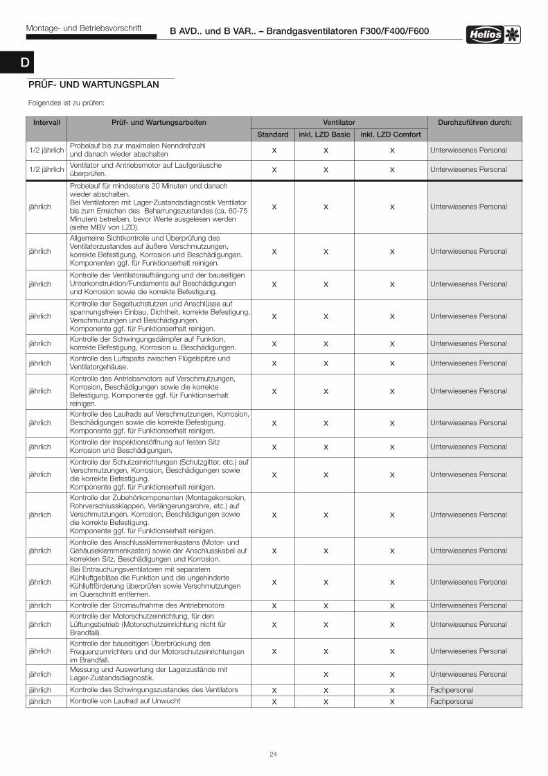
Intervall Prüf- und Wartungsarbeiten Ventilator Durchzuführen durch:
Standard inkl. LZD Basic inkl. LZD Comfort
1/2 jährlich Probelauf bis zur maximalen Nenndrehzahl und danach wieder abschalten x x x Unterwiesenes Personal
1/2 jährlich Ventilator und Antriebsmotor auf Laufgeräusche überprüfen. x x x Unterwiesenes Personal
jährlich
Probelauf für mindestens 20 Minuten und danach wieder abschalten.Bei Ventilatoren mit Lager-Zustandsdiagnostik Ventilatorbis zum Erreichen des Beharrungszustandes (ca. 60-75Minuten) betreiben, bevor Werte ausgelesen werden (siehe MBV von LZD).
x x x Unterwiesenes Personal
jährlich
Allgemeine Sichtkontrolle und Überprüfung desVentilatorzustandes auf äußere Verschmutzungen, korrekte Befestigung, Korrosion und Beschädigungen. Komponenten ggf. für Funktionserhalt reinigen.
x x x Unterwiesenes Personal
jährlichKontrolle der Ventilatoraufhängung und der bauseitigenUnterkonstruktion/Fundaments auf Beschädigungen und Korrosion sowie die korrekte Befestigung.
x x x Unterwiesenes Personal
jährlich
Kontrolle der Segeltuchstutzen und Anschlüsse aufspannungsfreien Einbau, Dichtheit, korrekte Befestigung,Verschmutzungen und Beschädigungen. Komponente ggf. für Funktionserhalt reinigen.
x x x Unterwiesenes Personal
jährlich Kontrolle der Schwingungsdämpfer auf Funktion, korrekte Befestigung, Korrosion u. Beschädigungen. x x x Unterwiesenes Personal
jährlichKontrolle des Luftspalts zwischen Flügelspitze und Ventilatorgehäuse. x x x Unterwiesenes Personal
jährlich
Kontrolle des Antriebsmotors auf Verschmutzungen,Korrosion, Beschädigungen sowie die korrekteBefestigung. Komponente ggf. für Funktionserhalt reinigen.
x x x Unterwiesenes Personal
jährlichKontrolle des Laufrads auf Verschmutzungen, Korrosion,Beschädigungen sowie die korrekte Befestigung. Komponente ggf. für Funktionserhalt reinigen.
x x x Unterwiesenes Personal
jährlichKontrolle der Inspektionsöffnung auf festen Sitz Korrosion und Beschädigungen. x x x Unterwiesenes Personal
jährlich
Kontrolle der Schutzeinrichtungen (Schutzgitter, etc.) aufVerschmutzungen, Korrosion, Beschädigungen sowiedie korrekte Befestigung.Komponente ggf. für Funktionserhalt reinigen.
x x x Unterwiesenes Personal
jährlich
Kontrolle der Zubehörkomponenten (Montagekonsolen,Rohrverschlussklappen, Verlängerungsrohre, etc.) aufVerschmutzungen, Korrosion, Beschädigungen sowiedie korrekte Befestigung. Komponente ggf. für Funktionserhalt reinigen.
x x x Unterwiesenes Personal
jährlichKontrolle des Anschlussklemmenkastens (Motor- undGehäuseklemmenkasten) sowie der Anschlusskabel aufkorrekten Sitz, Beschädigungen und Korrosion.
x x x Unterwiesenes Personal
jährlich
Bei Entrauchungsventilatoren mit separatemKühlluftgebläse die Funktion und die ungehinderteKühlluftförderung überprüfen sowie Verschmutzungen im Querschnitt entfernen.
x x x Unterwiesenes Personal
jährlich Kontrolle der Stromaufnahme des Antriebmotors x x x Unterwiesenes Personal
jährlichKontrolle der Motorschutzeinrichtung, für denLüftungsbetrieb (Motorschutzeinrichtung nicht fürBrandfall).
x x x Unterwiesenes Personal
jährlichKontrolle der bauseitigen Überbrückung desFrequenzumrichters und der Motorschutzeinrichtungenim Brandfall.
x x x Unterwiesenes Personal
jährlichMessung und Auswertung der Lagerzustände mit Lager-Zustandsdiagnostik. x x Unterwiesenes Personal
jährlich Kontrolle des Schwingungszustandes des Ventilators x x x Fachpersonal
jährlich Kontrolle von Laufrad auf Unwucht x x x Fachpersonal
PRÜF- UND WARTUNGSPLAN
Folgendes ist zu prüfen:

25
B AVD.. und B VAR.. – Brandgasventilatoren F300/F400/F600Montage- und Betriebsvorschrift
Intervall Prüf- und Wartungsarbeiten Ventilator Durchzuführen durch:
Standard inkl. LZD Basic inkl. LZD Comfort
5 JahreMotorlager austauschen
xHersteller oder vomHersteller autorisierteFachfirma
Nach Zu-standsan-zeige vonLZD,spätestensjedochnach10 Jahren
Motorlager austauschen
xHersteller oder vomHersteller autorisierteFachfirma
Keine zeit-liche Be-grenzung,erst nachWarnungder Zu-standsan-zeige vonLZD
Motorlager austauschen
xHersteller oder vomHersteller autorisierteFachfirma
Nach Zustand
Defekte, beschädigte und verschlisseneTeile/Komponenten an Ventilatoraufhängung, Ventilator,Antriebsmotor, Kühlluftgebläse, Schutzeinrichtungen,Anbauteile und Zubehör nach Bedarf ersetzen.
x x x Fachpersonal
siehe Motortypenschild
Motorlager mit Nachschmiereinrichtung nachfettenx x x Fachpersonal
D

Als Referenz am Gerät griffbereit aufbewahren! Druckschrift-Nr. 85573/12.16MBV-B AVD-2017-04
MBV-B VARD-2017-04
Service und InformationD HELIOS Ventilatoren GmbH + Co KG · Lupfenstraße 8 · 78056 VS-Schwenningen F HELIOS Ventilateurs · Le Carré des Aviateurs · 157 av. Charles Floquet · 93155 Le Blanc Mesnil CedexCH HELIOS Ventilatoren AG · Tannstrasse 4 · 8112 Otelfingen GB HELIOS Ventilation Systems Ltd. · 5 Crown Gate · Wyncolls Road · Severalls Industrial Park · A HELIOS Ventilatoren · Postfach 854 · Siemensstraße 15 · 6023 Innsbruck Colchester · Essex · CO4 9HZ
www.heliosventilatoren.de

Helios Smoke Extraction Fans
B AVD.. B VAR..
in temperature classes F300, F400, F600
EN
Helios VentilatorenINSTALLATION AND OPERATING INSTRUCTIONS
B AVD¬¬¬

Table of Contents
CHAPTER 1. SAFETY . . . . . . . . . . . . . . . . . . . . . . . . . . . . . . . . . . . . . . . . . . . . . . . . . . . . . . . . . . . . . . . . . . . . . . Page 11.0 Important information . . . . . . . . . . . . . . . . . . . . . . . . . . . . . . . . . . . . . . . . . . . . . . . . . . . . . . . . . . . . . . . . . . . Page 11.1 Warning instructions . . . . . . . . . . . . . . . . . . . . . . . . . . . . . . . . . . . . . . . . . . . . . . . . . . . . . . . . . . . . . . . . . . . Page 11.2 Safety instructions . . . . . . . . . . . . . . . . . . . . . . . . . . . . . . . . . . . . . . . . . . . . . . . . . . . . . . . . . . . . . . . . . . . . . Page 11.3 Area of application . . . . . . . . . . . . . . . . . . . . . . . . . . . . . . . . . . . . . . . . . . . . . . . . . . . . . . . . . . . . . . . . . . . . . Page 21.4 Boundaries . . . . . . . . . . . . . . . . . . . . . . . . . . . . . . . . . . . . . . . . . . . . . . . . . . . . . . . . . . . . . . . . . . . . . . . . . . Page 31.5 Protection against contact . . . . . . . . . . . . . . . . . . . . . . . . . . . . . . . . . . . . . . . . . . . . . . . . . . . . . . . . . . . . . . . Page 31.6 Personnel qualification . . . . . . . . . . . . . . . . . . . . . . . . . . . . . . . . . . . . . . . . . . . . . . . . . . . . . . . . . . . . . . . . . . Page 31.7 Air-flow direction and direction of rotation . . . . . . . . . . . . . . . . . . . . . . . . . . . . . . . . . . . . . . . . . . . . . . . . . . . Page 31.8 Speed control . . . . . . . . . . . . . . . . . . . . . . . . . . . . . . . . . . . . . . . . . . . . . . . . . . . . . . . . . . . . . . . . . . . . . . . . Page 41.9 Functional safety – Emergency operation . . . . . . . . . . . . . . . . . . . . . . . . . . . . . . . . . . . . . . . . . . . . . . . . . . . . Page 4
CHAPTER 2. GENERAL INFORMATION . . . . . . . . . . . . . . . . . . . . . . . . . . . . . . . . . . . . . . . . . . . . . . . . . . . . . . . Page 4 2.0 Warranty claims – Exclusion of liability . . . . . . . . . . . . . . . . . . . . . . . . . . . . . . . . . . . . . . . . . . . . . . . . . . . . . . Page 42.1 Certificates - Guidelines . . . . . . . . . . . . . . . . . . . . . . . . . . . . . . . . . . . . . . . . . . . . . . . . . . . . . . . . . . . . . . . . . Page 42.2 Shipping . . . . . . . . . . . . . . . . . . . . . . . . . . . . . . . . . . . . . . . . . . . . . . . . . . . . . . . . . . . . . . . . . . . . . . . . . . . . Page 42.3 Receipt . . . . . . . . . . . . . . . . . . . . . . . . . . . . . . . . . . . . . . . . . . . . . . . . . . . . . . . . . . . . . . . . . . . . . . . . . . . . . Page 42.4 Storage . . . . . . . . . . . . . . . . . . . . . . . . . . . . . . . . . . . . . . . . . . . . . . . . . . . . . . . . . . . . . . . . . . . . . . . . . . . . . Page 42.5 Smoke extraction series . . . . . . . . . . . . . . . . . . . . . . . . . . . . . . . . . . . . . . . . . . . . . . . . . . . . . . . . . . . . . . . . . Page 42.6 Performance data . . . . . . . . . . . . . . . . . . . . . . . . . . . . . . . . . . . . . . . . . . . . . . . . . . . . . . . . . . . . . . . . . . . . . Page 42.7 Noise data . . . . . . . . . . . . . . . . . . . . . . . . . . . . . . . . . . . . . . . . . . . . . . . . . . . . . . . . . . . . . . . . . . . . . . . . . . . Page 5
CHAPTER 3. INSTALLATION . . . . . . . . . . . . . . . . . . . . . . . . . . . . . . . . . . . . . . . . . . . . . . . . . . . . . . . . . . . . . . . . Page 53.0 Design . . . . . . . . . . . . . . . . . . . . . . . . . . . . . . . . . . . . . . . . . . . . . . . . . . . . . . . . . . . . . . . . . . . . . . . . . . . . . . Page 53.1 Assembly – Installation . . . . . . . . . . . . . . . . . . . . . . . . . . . . . . . . . . . . . . . . . . . . . . . . . . . . . . . . . . . . . . . . . . Page 63.2 Forced ventilation via centrifugal cooling air fan for F600 types . . . . . . . . . . . . . . . . . . . . . . . . . . . . . . . . . . . Page 73.3 Installation in fire area with centrifugal cooling air fan . . . . . . . . . . . . . . . . . . . . . . . . . . . . . . . . . . . . . . . . . . . Page 83.4 Fan installation outdoors . . . . . . . . . . . . . . . . . . . . . . . . . . . . . . . . . . . . . . . . . . . . . . . . . . . . . . . . . . . . . . . . Page 83.5 Technical data – Centrifugal cooling air fan B-KLG... . . . . . . . . . . . . . . . . . . . . . . . . . . . . . . . . . . . . . . . . . . . Page 93.6 Two-stage and parallel units . . . . . . . . . . . . . . . . . . . . . . . . . . . . . . . . . . . . . . . . . . . . . . . . . . . . . . . . . . . . .Page 103.7 Bearing condition diagnostics . . . . . . . . . . . . . . . . . . . . . . . . . . . . . . . . . . . . . . . . . . . . . . . . . . . . . . . . . . . Page 113.8 Minimum air gap in compliance with the material combinations . . . . . . . . . . . . . . . . . . . . . . . . . . . . . . . . . . Page 113.9 Maximum permissible vibration limits pursuant to ISO 14694 / ISO 10816-3 . . . . . . . . . . . . . . . . . . . . . . . . Page 123.10 Centre of gravity position . . . . . . . . . . . . . . . . . . . . . . . . . . . . . . . . . . . . . . . . . . . . . . . . . . . . . . . . . . . . . . . Page 123.11 Recommended tightening torques for mounting screws . . . . . . . . . . . . . . . . . . . . . . . . . . . . . . . . . . . . . . . Page 123.12 Electrical connection . . . . . . . . . . . . . . . . . . . . . . . . . . . . . . . . . . . . . . . . . . . . . . . . . . . . . . . . . . . . . . . . . . Page 133.13 Commissioning . . . . . . . . . . . . . . . . . . . . . . . . . . . . . . . . . . . . . . . . . . . . . . . . . . . . . . . . . . . . . . . . . . . . . . Page 133.14 Operation . . . . . . . . . . . . . . . . . . . . . . . . . . . . . . . . . . . . . . . . . . . . . . . . . . . . . . . . . . . . . . . . . . . . . . . . . . . Page 13
CHAPTER 4. SERVICING AND MAINTENANCE . . . . . . . . . . . . . . . . . . . . . . . . . . . . . . . . . . . . . . . . . . . . . . . . Page 144.0 Servicing and maintenance . . . . . . . . . . . . . . . . . . . . . . . . . . . . . . . . . . . . . . . . . . . . . . . . . . . . . . . . . . . . . Page 144.1 Cleaning . . . . . . . . . . . . . . . . . . . . . . . . . . . . . . . . . . . . . . . . . . . . . . . . . . . . . . . . . . . . . . . . . . . . . . . . . . . . Page 144.2 Information – Fault causes . . . . . . . . . . . . . . . . . . . . . . . . . . . . . . . . . . . . . . . . . . . . . . . . . . . . . . . . . . . . . . Page 144.3 Spare parts . . . . . . . . . . . . . . . . . . . . . . . . . . . . . . . . . . . . . . . . . . . . . . . . . . . . . . . . . . . . . . . . . . . . . . . . . Page 154.4 Standstill and disposal . . . . . . . . . . . . . . . . . . . . . . . . . . . . . . . . . . . . . . . . . . . . . . . . . . . . . . . . . . . . . . . . . Page 16
CHAPTER 5. TECHNICAL DATA . . . . . . . . . . . . . . . . . . . . . . . . . . . . . . . . . . . . . . . . . . . . . . . . . . . . . . . . . . . . . Page 165.0 Technical data . . . . . . . . . . . . . . . . . . . . . . . . . . . . . . . . . . . . . . . . . . . . . . . . . . . . . . . . . . . . . . . . . . . . . . . Page 165.1 Type key . . . . . . . . . . . . . . . . . . . . . . . . . . . . . . . . . . . . . . . . . . . . . . . . . . . . . . . . . . . . . . . . . . . . . . . . . . . Page 175.2 Type plate . . . . . . . . . . . . . . . . . . . . . . . . . . . . . . . . . . . . . . . . . . . . . . . . . . . . . . . . . . . . . . . . . . . . . . . . . . Page 175.3 Motor type plate . . . . . . . . . . . . . . . . . . . . . . . . . . . . . . . . . . . . . . . . . . . . . . . . . . . . . . . . . . . . . . . . . . . . . Page 17
CHAPTER 6. WIRING DIAGRAM OVERVIEW . . . . . . . . . . . . . . . . . . . . . . . . . . . . . . . . . . . . . . . . . . . . . . . . . . Page 186.0 Wiring diagrams . . . . . . . . . . . . . . . . . . . . . . . . . . . . . . . . . . . . . . . . . . . . . . . . . . . . . . . . . . . . . . . . . . . . . . Page 186.1 Basic plan (SS-1023) . . . . . . . . . . . . . . . . . . . . . . . . . . . . . . . . . . . . . . . . . . . . . . . . . . . . . . . . . . . . . . . . . . Page 206.2 Basic plan for F600 (SS-1024) . . . . . . . . . . . . . . . . . . . . . . . . . . . . . . . . . . . . . . . . . . . . . . . . . . . . . . . . . . . Page 21
CHAPTER 7. . . . . . . . . . . . . . . . . . . . . . . . . . . . . . . . . . . . . . . . . . . . . . . . . . . . . . . . . . . . . . . . . . . . . . . . . . . . . Page 227.0 Commissioning report . . . . . . . . . . . . . . . . . . . . . . . . . . . . . . . . . . . . . . . . . . . . . . . . . . . . . . . . . . . . . . . . . Page 227.1 Test and maintenance plan . . . . . . . . . . . . . . . . . . . . . . . . . . . . . . . . . . . . . . . . . . . . . . . . . . . . . . . . . . . . . Page 24
Expiry of service life, disposalParts and components of the fan, whose service life has expired, e.g. due to wear and tear, corrosion, mechanical load, fatigue and/or other effects that cannot bedirectly discerned, must be disposed of expertly and properly after disassembly in accordance with the national and international laws and regulations. The same also applies to auxiliary materials in use. Such as oils and greases or other substances.The intended and unintended further use of worn parts, e.g. impellers, rolling bearings, filters, etc. can result in danger to persons, the environment as well as machines and systems. The corresponding operator guidelines applicable on-site must be observed and used.
ENGLISH

� DANGER
� WARNING
� CAUTION
1
B AVD.. and B VAR.. – Smoke Extraction Fans F300/F400/F600Installation and Operating Instructions
1.0 Important informationIn order to ensure complete and effective operation and for your own safety, all of the following instructions should beread carefully and observed.This document should be regarded as part of the product and as such should be kept accessible and durable. Theoperator is responsible for observing all plant-related safety regulations.The approval associated with the unit and the declaration of performance must be observed!
1.1 Warning instructions The adjacent symbols are safety-relevant warning symbols. All safetyregulations and/or symbols in must be absolutely adhered to, so that anydangerous situations are avoided!
1.2 Safety instructions
l Protective glassesServes to protect against eye injuries.
p Ear protectorsServes to protect against all kinds of noise.
r Protective clothingPrimarily serves to protect against contact with moving parts.Do not wear rings, chains or other jewellery.
n Protective glovesProtective gloves serve to protect the hands against rubbing, abrasions, cutsor more profound injuries, as well as contact with hot surfaces.
m Protective footwearProtective footwear serves to protect against heavy falling parts and from slip-ping on slippery surfaces.
Hair netThe hair net primarily serves to protect long hair against contact with movingparts.
Special regulations apply for use, connection and operation of smoke ventilati-on fans. Consultation is required in case of doubt. The federal and regionalfire protection regulations must be observed! Further information can befound in the relevant standards, federal laws, regional building codes andspecial building codes.
�With regard to all work on the fan, the generally applicable safety at work and accident prevention regulations must be observed!
• It must be ensured that the smoke extraction fan will operate until electro-mechanical failure in a smoke extraction situation.Existing speed regulations or motor protection devices must be bridged!
• The unit must be fully isolated from the power supply and secured againstbeing inadvertently switched on again before all maintenance and installationwork or before opening the terminal compartment! The electrical connectionmust only be carried out by an authorised electrician according to thefollowing wiring diagrams!
• Transport fan in packaging until installation!
CHAPTER 1
SAFETY
EN

2
B AVD.. and B VAR.. – Smoke Extraction Fans F300/F400/F600Installation and Operating Instructions
• Only transport smoke extraction fans using means of transport that areappropriate for the weight, wear protective gloves during transport!
• Observe attached transportation diagram!• Wear protective gloves/footwear when unpacking the unit.• Ensure the suitable load capacity and properties of the mounting surface
and use suitable mounting material.• The installation area must be designed so that people cannot be endange-
red by hot gases.• The outlet area of the fan and motor cooling system must be free of flamma
ble materials and it must not be accessible to persons.• It must be checked whether ear protection is necessary for the installation
situation.• The operator is responsible for observing all plant-related safety regulations!• Abnormally frequent activation/deactivation is not permissible.• Protection against contact for the impeller must be ensured pursuant to DIN
EN 13857.• It must be ensured that no water can get into the smoke extraction fan!• In order to maintain operational safety, a regular vibration check must be
carried out! Alternatively, the installation of an on-site vibration monitoringsystem is recommended.The information and permissible vibration limits according to ISO 14694from the table on page 12, section 3.9 must be observed.
• The planner and operator must ensure easy access for inspection and clea-ning work!
• A uniform inflow and free outlet must be ensured.
1.3 Area of application– Normal use:Operation within the characteristic curve of the respective unit (see catalogue). Vibrations and an increase in noisegeneration indicate operation outside of the characteristic curve.
Ventilation mode:Conveyance of normal or slightly dusty (particle size < 10 µm), less aggressive and humid air, in moderate climates attemperatures in the range of -20 °C to +40 °C, with stationary installation of the fan.Smoke extraction mode:One-off conveyance of smoke type F300 - 300 °C, 2h; Type F400 - 400 °C, 2h; Type F600 - 600 °C, 2h tested ac-cording to DIN EN 12101-3.Type F600 with forced ventilation: For sufficient cooling air vent opening (max. 40 °C) and reliable discharging of out-going air (max. 250 °C).Installation:In fire area, outside fire area, outdoors (protected from the elements) vertical and horizontal installation possible.
– Reasonably foreseeable misuse:The fans are not suitable for operation under difficult conditions, such as high levels of humidity, aggressive media,long standstill periods, heavy contamination, excessive loads due to climatic, technical or electronic influences. Thesame applies for the mobile use of fans (vehicles, aircraft, ships, etc.).
– Improper, prohibited use:Outdoor installation without effective weather protection or in direct contact with water. Conveyance of explosive gasmixtures/media. Installation in an explosive area/atmosphere. Operation without standardised safety devices (e.g.protective grille). Conveyance of solids or solid content > 10 µm in the conveyed medium and liquids. Conveyanceof abrasive and/or fan material-corrosive media. Conveyance of conveyed medium containing fat. Smoke extractionwith motor protection device or frequency converter.
EN

3
B AVD.. and B VAR.. – Smoke Extraction Fans F300/F400/F600Installation and Operating Instructions
1.4 BoundariesSpatial boundaries:A straight, flat pipe section of 2.5 x D must be ensured before and after the fan. In any case, a suction nozzle must beplaced at the beginning of the pipe section on the intake-side of the fan. When using at the start or end of a pipeline,the area without pipe must also be kept clear in the same way. The outlet opening must protrude at least 1 m overcomponents made of flammable substances or be located 1.5 m away from these – horizontal measurement. Thedischarge direction must not be in the direction of flammable components! The discharge-side environmentmust not be accessible for persons. The fan must be easily accessible for cleaning and maintenance purposes, parti-cularly the terminal boxes.Power supply interface:Connection only with fixed wiring with function preservation, 3 phases + PE, a full motor protection device (must be bridged in smoke extraction situation). An option to fully isolate the unit from the power supply is mandatory! Depending on the local circumstances, an isolator switch may be necessary for full isolation from the power supply. Time:Ventilation mode:The motor bearings must be replaced after 5 years. When using bearing condition diagnostics, different regulations shall apply, see test and maintenance plan.Smoke extraction mode:The unit must be disposed of following smoke extraction operation!
1.5 Protection against contactThe generally applicable safety at work and accident prevention regulations must be observed for installation!The operator is responsible for observing these regulations!– Contact with rotating parts must be avoided. It must be ensured that there must be no persons, textiles or other
materials that could be sucked up, such as clothing, located in the intake area.– Protection against contact may be necessary on the suction side depending on the installation conditions.
Appropriate protection grilles are available as accessories.– Fans which are protected by their installation method (e.g. installation in ventilation ducts or closed assemblies) do
not require protection guards if the plant provides the necessary level of safety. Please note that the operator isresponsible for complying with the current standard (DIN EN 13857) and can be held liable for accidents as aconsequence of missing protection systems.
1.6 Personnel qualification– All electrical work as well as the start-up must only be carried out by qualified electricians.– Installation, servicing and maintenance may be carried out by specialists (e.g.: industrial mechanics, mechatronics
engineers, metal workers or persons with comparable training) with the exception of electrical work.– In case of repair work to the smoke extraction fans, these must be returned to Helios.
1.7 Air-flow direction and direction of rotation
� WARNINGParts ejected from the fan may damage your eyes!Wear protective glasses when checking the direction of rotation!
� WARNING– The rotating impeller can sever or trap your fingers/arms!– Operation only with mounted safety fittings!– Risk of damage!– Do not insert objects into the rotating impeller!
The air flow direction is blowing over the motor (see air and direction of rotation arrows).The correct direction of rotation is right clockwise when viewing the impeller from the front.
The direction of rotation may only be checked when the fan is switched off and coasting!
Three-phase current types must be connected in the clockwise field of rotation by switching two phases for anti-clockwise rotation. The incorrect direction of rotation can lead to overheating and lack of fan performance!
EN
� NOTE
Fig.1 Fig.2
B AVD¬¬¬
Air flow direction
Air flow direction
� WARNING
� WARNING
� WARNING
� ATTENTION
l

4
B AVD.. and B VAR.. – Smoke Extraction Fans F300/F400/F600Installation and Operating Instructions
1.8 Speed control– The 1-speed series B VAR.. and B AVD.. F300/F400/F600 are equipped with thermistors (PTC) and may be
operated in ventilation mode using a frequency converter with an all-pole effective sinusoidal filter (Helios FU-CS).– The speed control of all series is only permitted in ventilation mode and with a frequency converter with an all-pole
effective sinusoidal filter.– The smoke extraction fan must be operated at a nominal speed.– The speed control must be bridged in a smoke extraction situation!
1.9 Functional safety – Emergency operationWhen using the fan in an important supply function, the plant is to be designed so that emergency operation is auto-matically guaranteed in case of fan failure. Suitable solutions are, for example: parallel operation of two less powerfulunits with a separate electric circuit, standby fan, alarm systems and emergency ventilation systems.In order to maintain the smoke extraction function, an additional power supply is required in case of a power failure.The wiring must have function preservation.
2.0 Warranty claims – Exclusion of liabilityAll versions of this documentation must be observed, otherwise the warranty shall cease to apply. The same appliesto liability claims against Helios. The use of accessory parts, which are not recommended or offered by Helios, is notpermitted. Any possible damages are not covered by the warranty. Changes and modifications to the unit are notpermitted and lead to a loss of conformity, and any warranty and liability shall be excluded in this case.
2.1 Certificates - GuidelinesIf the unit is installed correctly and used to its intended purpose, it conforms to all applicable regulations and EUguidelines at its date of manufacture.
2.2 ShippingThe fan is packed ex works in such a way that it is protected against normal transport strain. Carry out the shippingcarefully. It is recommended to leave the fan in the original packaging. The fan must be kept in the casing or theprovided lifting lugs for transportation or installation – Observe transportation diagram! In this respect, only use ap-propriate lifting equipment and fastening devices. Weight information can be found in the table Chapter 5.0 on page 16 or the unit label.Do not transport fan on the connection cables, terminal box or impeller!Do not stand under suspended loads!
2.3 ReceiptThe shipment must be checked for damage and correctness immediately upon delivery. If there is any damage,promptly report the damage with the assistance of the transport company. If complaints are not made within theagreed period, any claims could be lost.
2.4 StorageWhen storing for a prolonged time, the following steps are to be taken to avoid damaging influences: Motor protection bydry, airtight and dust-proof packaging (plastic bag with desiccant and humidity indicators). The storage place must bewater proof, vibration-free and free of temperature variations. Storage temperature -20 °C to +60 °C, and these limitsmust not be exceeded. The motor bearings must be turned at regular intervals (10 turns per month). In case of a stora-ge period of more than three months or motor standstill, maintenance must be carried out before commissioning. Inthis respect, the silent, free movement of the impeller must be checked. The motor bearings must be replaced aftera 2-year storage period. When transhipping (especially over longer distances) check if the packing is adequate formethod and manner of transportation. Damages due to improper transportation, storage or commissioning are notliable for warranty.
2.5 Smoke extraction seriesThese installation and operating instructions describe the Helios smoke extraction fan series:
Binding information on the individual fan types can be found on the type plate.
2.6 Performance dataThe motor type plate gives an indication of the electrical values; which must be coordinated with the local supply network. The fan performances* were established on a test stand according to DIN EN ISO 5801:2010-12; they apply tothe nominal speed and standard design using an inlet nozzle, without a protection guard with unhinderedinflow and outflow and a pressure-side pipe section with 2.5 x diameter length. In this respect, different versions andunfavourable installation and operating conditions can lead to a reduction of output.
CHAPTER 2
GENERAL INFORMATION
Series Temperature class DiameterLow-pressure axial smoke extraction fans
B AVD..F300 Ø 500-1250 mmF400 Ø 500-1250 mmF600 Ø 500-1250 mm
Series Temperature class DiameterHigh-pressure in-line smoke extraction fans
B VAR..F300 Ø 280-1000 mmF400 Ø 500-1000 mmF600 Ø 500-1000 mm
B AVD¬¬¬
� DANGER
EN
� ATTENTION

5
B AVD.. and B VAR.. – Smoke Extraction Fans F300/F400/F600Installation and Operating Instructions
CHAPTER 3
INSTALLATION
B AVD¬¬¬
2.7 Noise dataThe noise data* also refers to the aforementioned directive. Casing variations, unfavourable operating conditions and many other things can lead to an increase in the specified catalogue values. Data that refers to certain distances (1 m,2 m, 4 m) apply to free field conditions. With regard to installation, the sound pressure level can differ significantly fromthe catalogue data, as it is highly dependent on the installation conditions, i.e. on the absorption capability of the room,the room size among other factors.
3.0 Design
Series B VAR 280-1000 F300 / B VAR 500-1000 F400The high-pressure in-line smoke extraction fan is a direct-driven fan where the motor is positioned in the airflow. Theair flow direction is blowing via the motor. The axial flow pattern allows a low-loss, linear airflow and ensures a high fanefficiency. The cylindrical casing with flanges on both ends, integrated guide vane and motor support are made from galvanised sheet steel.The semi-axial impeller with eight curved blades is made from galvanised sheet steel or B VARD280-315 F300 from aluminium. The dynamic balancing is carried out according to ISO 1940 T1, class 6.3.Technical data: IEC three-phase motors, 400 Volt, 50 Hz, IP 55, insulation class H
Series B VAR 500-1000 F600Like above, but motor is encapsulated and additional supply air fan required.
Series B AVD 500-1250 F300 / F400The low-pressure axial smoke extraction fan is a direct-driven fan where the motor is positioned in the airflow. Theair flow direction is blowing via the motor. The axial flow pattern allows a low-loss, linear airflow and ensures a high fanefficiency. The cylindrical casing with flanges on both ends, integrated guide vane and motor support are made from galvanised sheet steel.The high-performance impeller with nine profiled blades is made from aluminium. The dynamic balancing is carried outaccording to ISO 1940 T1, class 6.3.Technical data: IEC three-phase motors, 400 Volt, 50 Hz, IP 55, insulation class H
Series B AVD 500-1250 F600The cylindrical casing with flanges on both ends, integrated guide vane and motor support are made from galvanisedsheet steel. The motor is encapsulated and an additional supply air fan required. The high-performance impeller with five profiled blades is made from galvanised sheet steel. The dynamic balancing is carried out according to ISO 1940T1, class 6.3.Technical data: IEC three-phase motors, 400 Volt, 50 Hz, IP 55, insulation class H
Overview: Smoke extraction fan B VAR.. with accessory parts (horizontal)
Suction nozzle ASD-SGD
Back-draughtshutter RVS
Counterflange FRProtection grille SG
Flexible connector STSB
Fig.3
Vibration damper SDD..for pressure load
Mounting bracket MK
Mounting bracket MK
Vibration damper SDZ..for tensile load
B VAR..Extension duct VR (optional)- Required for protruding motorsee section 3.10
Duct silencer RSD
EN
* (performance and noise data from the currently valid Helios documents and the internet)

6
B AVD.. and B VAR.. – Smoke Extraction Fans F300/F400/F600Installation and Operating Instructions
Installation examples – Vertical F300/400: Smoke extraction fan B VAR.. with accessory parts
3.1 Assembly – Installation
� WARNING The fan can tip over and crush limbs during installation! Note transportation diagram and centre of gravity! Wear protective footwear.
All occupational safety regulations, installation conditions and declarations of performance (DIBt technical approval) must be observed for assembly and installation! The smoke extraction fans must be positioned and installed so that inspection, maintenance and repair work can be carried out easily and safely.
Installation conditions VA: Suitable for “vertical installation”HA: Suitable for “horizontal installation”LB: For “Ventilation mode” -20 °C to +40 °CIB: Can be installed in “Fire area”
Fan without insulating layer, the cooling air duct must be insulated inside the smoke extraction area with L120 DIN 4102-4
AB (WG): “Outside the fire area, thermally insulated”In sufficiently ventilated rooms, fan with insulating layer F300 L60 or F400 and F600 L120 according to DIN 4102-4
IF: “Outside” fan without insulating layer if it is ensured that precipitation cannot penetrate the smoke extrac-tion fan
ZB: “Forced ventilation” via cooling air duct Inlet temperature of cooling air in the motor casing max. 40 °C, not minimum cooling air (mounting accessories: centrif. cooling air fan, weather protection cover on-site).
Connection of smoke extraction ducts with mounting accessories:– Flexible connectorsFlexible connectors (elastic sleeves) STSB... F400 or F600 must be used for the intake and/or outlet-side connectionof smoke extraction fans to smoke extraction ducts. When mounting the flexible connectors, it must be ensured thatthe installation gap 145 mm is maintained and this prevents tension load or compression load. Do not mount the elasticconnectors so that they are staggered. This will prevent performance reduction and noise generation.– Extension ductWhen installing in duct sections, it must be ensured that there is a sufficiently long straight duct section 2.5 x D beforeand after the fan (e.g. with extension duct VR...), as otherwise significant performance reductions and noise genera-tion can be expected.– Vibration dampersIn order to prevent the transmission of vibrations, the use of steel spring/vibration dampers SDD 1F 4-10 and SDZ1F 4-9 is recommended. The arrangement of attenuators, mounting brackets and vibration dampers can be seen inFig. 6 to 9 and also Fig. 17.
Fig.4 Fig.5
Extension ductVR
B VAR..
Mounting ringvertical MRV..
Vibration damper SDD..for pressure load
Extension ductVR
B VAR..
Vibration damper SDZ..for tensile load
Mounting ringvertical MRV..
� WARNING
EN
nm

7
B AVD.. and B VAR.. – Smoke Extraction Fans F300/F400/F600Installation and Operating Instructions
– AttenuatorFigure 9: Duct installation with intake and outlet-side attenuators RSD... F400 with mounting brackets MK. The intake-side attenuator must be mounted at the inlet, and the outlet-side attenuator on the outlet together with the flexibleconnectors.– Backdraught shutterAutomatic backdraught shutter RVS... F400 with spring reset:Horizontal installation possible in any direction, vertical installation possible with upward flow.
3.2 Forced ventilation via centrifugal cooling air fan for F600 typesThe motor cooling for the Helios F600 smoke extraction fans takes place in both smoke extraction and ventilation modevia separate centrifugal cooling air fans (types B KLG, accessories). These cooling air fans are monitored in ventilationmode by flow monitors (type SWE, accessories).– Ventilation modeThe cooling air fan must be activated simultaneously with the smoke extraction fan in ventilation mode. If the airflowmonitor signals a fault, then it is no longer guaranteed that the smoke extraction fan is supplied with sufficient coolingair. In order to prevent damage to the smoke extraction fan, it must be immediately deactivated and a fault signal mustbe issued.– Smoke extraction modeThe cooling air fan must be activated simultaneously with the smoke extraction fan in smoke extraction mode. If theairflow monitor or the smoke extraction fan motor protection device signals a fault, smoke extraction operations mustnot be interrupted. A fault signal must be issued. The smoke extraction fan will run until electromechanical destruction.
Flexible connectorSTSB
Extension ductVR
Fan B VAR
Vibration dampers Duct 2.5 x DMounting bracket
Protectiongrille Counterflange FR
Suction nozzleASD-SGD
Fig.7
Fig.6
Fan B VAR
Flexible connectorSTSB
Vibration dampersProtection
grille
Suction nozzleASD-SGD
Extension ductVR
DuctCounterflange FR
Mounting bracket
Vibration dampers
Vibration dampers
STSBFlexible connector
STSB Extension ductVR
Flexible connectorSTSB
Duct
Duct
DuctFan
B AVD
Fan B AVD
Mounting bracket
Extension ductVR
Fig.8
Fig.9Duct
Flexible connectorSTSB
Mounting bracket
AttenuatorRSD
AttenuatorRSD
B AVD¬¬¬
EN

8
B AVD.. and B VAR.. – Smoke Extraction Fans F300/F400/F600Installation and Operating Instructions
EN 3.3 Installation of F600 smoke extraction fan in fire area with centrifugal cooling air fan for motor cooling
– Installation condition ZB = Forced ventilation (see type plate)In order to ensure the motor cooling for the F600 series, separate centrifugal cooling air fans (e.g. B KLG 500 or B KLG1000) are necessary accessories. The cooling air fan must be installed outside of the fire area (smoke section) in suffi-ciently ventilated rooms or outside with weather protection. In this respect, the supply air temp. óf 40 °C must not be ex-ceeded (Fig.10). For information on the minimum cooling air flow volumes for the respective smoke types, see the sel-ection tables on page 9.
� DANGER– The cooling air outlet temperature can be up to 250 °C!– The outgoing air from the motor casing must be transported outside or into a sufficiently ventilated room!– The environment/utility room must be sufficiently ventilated!– The discharge direction must not be in the direction of flammable components.– The discharge-side environment must not be accessible for persons!
Even when operating the F600 smoke extraction fan for ventilation purposes, motor cooling through a centrifugal coo-ling air fan is mandatory, because the drive motor is not cooled in its casing by the air flow volume of the smoke ex-traction fan. Otherwise, it could lead to a drive motor failure due to overheating.
– Terminal boxThe terminal box for the F600 smoke extraction fan is mounted to the casing in the factory. In case of installation in thefire area (IB), the terminal box must be dismantled from the casing and attached outside of the fire area (see Fig. 10). Inthis respect, the connection line from the terminal box to the drive motor (line length must be adjusted on site) must beled through the insulated cooling air duct to the smoke extraction fan.
3.4 Fan installation outsideHelios smoke extraction fans of type B AVD... and B VARD... are suitable for use outside under normal weather con-ditions in installation arrangements for horizontal or vertical air flow directions. The penetration of precipitation into thesmoke extraction fan must be prevented.In particular, the inlet and outlet opening area must be protected by mounting extension ducts (for horizontal air flowdirection) or e.g. an on-site weather protection cover (end/beginning of a pipe/duct section for vertical air flow direc-tion).The openings in the fan casing must be protected against the penetration of precipitation by a suitable installationposition (openings on side or below). In this respect, particular attention must be paid to the casing feed-through forthe supply line between the casing terminal box and motor connection, as well as the cooling air outlet openings fromthe motor casing for F600 smoke extraction fans.Centrifugal cooling air fans for F600 smoke extraction fans must be protected against weather influences by on-siteprotection devices (e.g. weather protection cover).With regard to the insulation of smoke extraction fans installed outside, it must be ensured that precipitation cannot pe-netrate into the insulation (e.g. weather protection cover).
Fig.10
Cooling air duct with thermal insu-lation and connection line from theterminal box
Environment/utility room (max. 40 °C with backflow)
¬Fire area¬
� DANGER

9
B AVD.. and B VAR.. – Smoke Extraction Fans F300/F400/F600Installation and Operating Instructions
EN
Type Fan Cool. air vol. Quant. Casing still available
B VAR B KLG required, V· [m3/h] Piece [Pa]1 Dpex [Pa]2
500 500 250 1 95 314
560 500 340 1 175 187
630 1000 445 1 80 129
710 1000 565 1 125 73
800 500 700 2 190 160
900 1000 850 2 70 140
1000 1000 1000 2 100 106
1120 - - - - -
1250 - - - - -
Centrifugal cooling air fanfor smoke extraction fans F600 for motor cooling. A flowmonitor (type SWE, Ref. no. 0065, accessories) is requi-red for monitoring the motor cooling in ventilation mode.
Technical dataType B KLG 1000 Ref. no. 2799Protection class IP44 Power 175 WattVoltage 400 Volt max. ambient temperature 40 °CFrequency 50 Hz Speed 1330 1/minCurrent 0.39 Amp. Volume flow 1030 m3/hWiring diagram SS-1019
Dimensions in mm
Centrifugal cooling air fanwith separately fitted thermal contact for smoke extrac-tion fans F600 for motor ventilation. A flow monitor (typeSWE, Ref. no. 0065, accessories) is required for monito-ring the motor cooling in ventilation mode.Technical dataType B KLG 500 Ref. no. 2798Protection class IP44 Power 160 WattVoltage 230 Volt max. ambient temperature 40 °CFrequency 50 Hz Speed 2400 1/minCurrent 0.7 Amp. Volume flow 500 m3/hWiring diagram SS-1018
Dimensions in mm
n=2400 1/min n=1330 1/minB KLG 500 B KLG 1000
Selection table – Cooling air volume for B VAR..
Cooling air temp. max. 40 °C 1 Resistance in fan/cooling system 2 Available pressure at cooling air fan outlet
Cooling air temp. max. 40 °C 1 Resistance in fan/cooling system 2 Available pressure at cooling air fan outlet
Selection table – Cooling air volume for B AVD..
Type Fan Cool. air vol. Quant. Casing still available
B AVD B KLG required, V· [m3/h] Piece [Pa]1 Dpex [Pa]2
500 500 250 1 95 314
560 500 280 1 115 290
630 500 315 1 150 235
710 500 355 1 190 155
800 500 400 1 65 207
900 1000 450 1 80 129
1000 1000 500 1 100 106
1120 1000 875 2 75 135
1250 1000 1250 2 155 31
Type Ø F600 B AVD dim. A (mm) B VAR dim. A (mm)
500 626 626
560 626 626
630 626 696
710 626 696
800 626 626
900 696 696
1000 696 696
1120 696 -
1250 696 -
Selection table – Cooling air fan B KLG..
Dimensions in mm
B KLG 1000
B KLG 500
Assignment, see table opposite.
3.5 Technical data – Centrifugal cooling air fan B KLG...
Pa Pa
m3/hm3/h
Fig.11 Fig.12B KLG 500 B KLG 1000
Fig.13

EN
10
B AVD.. and B VAR.. – Smoke Extraction Fans F300/F400/F600Installation and Operating Instructions
3.6 Two-stage and parallel unitsThe various requirements concerning pressure increases, conveying capacities and space requirements are frequentlyfulfilled by two-stage Z or parallel P units in the area of Technical Building Equipment (TGA). The Helios range (see salesdocuments) offers corresponding mounting kits for the respective construction:
Dimensions:
3.7 Bearing condition diagnostics Type: LZD-Basic and LZD-Comfort
The Helios bearing condition diagnostics system serves to securely monitor the functionality of motor bearings inthe drive motor of the smoke extraction fan. The system optionally allows the early detection of imminent bearingdamage by constantly or occasionally monitoring the bearing conditions. The bearings are not replaced periodically,but depending on the actual wear. In this respect, the test and maintenance plan in these Installation and OperatingInstructions must be observed. Before operation and the use of bearing condition diagnostics, the separate Installationand Operating Instructions for the monitoring system must be observed.
Information on other smoke extraction accessories can be found on the internet (www.heliosselect.de), main catalogueor the Helios sales documentation.
Two-stage design / mounting kit MP-ZTwo fans connected in series (Fig.14) ensure theunrivalled power density and advantageous installa-tion due to minimum space requirement.The two fans are arranged in sequence andconnected with extension ducts.� Vertical mounting ring is not possible (MRV)
Scope of delivery:- Extension ducts (2 pcs.) incl. mounting kit
(hexagon head screws, nuts, spring washers).
Parallel unit / mounting kit MP-PTwo fans connected in parallel (Fig.15) provide lar-ge air volumes with the corresponding pressure ra-te and they meet the requirements for garage venti-lation and smoke extraction in particular.Two identical fans arranged side by side workin the same duct system.Scope of delivery:- Extension ducts (2 pcs.),- Backdraught shutters (2 pcs.),- Mounting brackets (4 pcs.)- Mounting rails (2 pcs.)- Mounting kits (hexagon head screws, nuts, spring
washers, washers and threaded plate).
MP-Z MP-P
Ø A B C D E A B C D E F G1) H I J
280 280 322 346 1200 8x Ø9.5 280 322 346 900 0 558 390-470 980 281 8x Ø9.5
315 315 356 380 1200 8x Ø9.5 315 356 380 900 0 548 420-520 1085 316,5 8x Ø9.5
355 355 395 420 1200 8x Ø9.5 355 395 420 900 0 548 460-580 1120 336 8x Ø9.5
400 400 438 465 1320/1360* 12x Ø9.5 400 438 465 990/1010*
0 607/626*
510-580 1120 346,5 12x Ø9.5
450 450 487 515 1360 12x Ø9.5 450 487 515 1010 10 626 560-650 1200 397 12x Ø9.5
500 500 541 565 1360/1690* 12x Ø9.5 500 541 565 1010 40 626 615-730 1500 445 12x Ø9.5
560 560 605 640 1840 16x Ø11.5 560 605 640 1250 65 865 700-820 1600 477 16x Ø11.5
630 630 674 710 1840 16x Ø11.5 630 674 710 1320 115 855 760-920 1700 527 16x Ø11.5
710 710 751 810 2140 16x Ø11.5 710 751 810 1470 155 995 860-1020 1900 639 16x Ø11.5
800 800 837 900 1980 24x Ø11.5 800 837 900 1410 200 914 950-1120 2000 689 24x Ø11.5
900 900 934 1000 2400 24x Ø11.5 900 934 1000 1410 250 914 1070-1240 2200 749 24x Ø11.5
1000 1000 1043 1100 2560 24x Ø11.5 1000 1043 1100 1490 300 994 1200-1370 2400 814 24x Ø11.5
Fig.14 Fig.15
* Additional extension duct 1) Distance depending on accessories

11
B AVD.. and B VAR.. – Smoke Extraction Fans F300/F400/F600Installation and Operating Instructions
EN3.8 Minimum air gap in compliance with the material combinations
Move impeller by hand to check unhindered running of impeller!Before installation, check the minimum air gap (MLS) between impeller tip and casing according to the following table:
If the observed values do not correspond to the specifieddimensions, the fan must not be installed or operated. For questions, please contact Helios customer service “TGA”.Own repair attempts are strictly prohibited!
Type TK MLS (in mm) Type TK MLS (in mm)
B VAR.. 280 F300 2.0
B VAR.. 315 F300 2.0
B VAR.. 355 F300 2.5
B VAR.. 400 F300 2.5
B VAR.. 450 F300 2.5
B VAR.. 500 F300 2.5 B AVD.. 500 F300 4.5
B VAR.. 560 F300 3.0 B AVD.. 560 F300 4.6
B VAR.. 630 F300 3.0 B AVD.. 630 F300 5.2
B VAR.. 710 F300 3.5 B AVD.. 710 F300 5.7
B VAR.. 800 F300 4.0 B AVD.. 800 F300 5.8
B VAR.. 900 F300 4.5 B AVD.. 900 F300 6.9
B VAR.. 1000 F300 5.0 B AVD.. 1000 F300 7.0
B AVD.. 1120 F300 8.1
B AVD.. 1250 F300 8.8
B VAR.. 500 F400 4.6 B AVD.. 500 F400 5.6
B VAR.. 560 F400 5.1 B AVD.. 560 F400 6.2
B VAR.. 630 F400 5.8 B AVD.. 630 F400 7.0
B VAR.. 710 F400 6.5 B AVD.. 710 F400 7.9
B VAR.. 800 F400 7.3 B AVD.. 800 F400 8.9
B VAR.. 900 F400 8.2 B AVD.. 900 F400 10.0
B VAR.. 1000 F400 9.1 B AVD.. 1000 F400 11.1
B AVD.. 1120 F400 12.4
B AVD.. 1250 F400 13.9
B VAR.. 500 F600 7.0 B AVD.. 500 F600 6.0
B VAR.. 560 F600 8.0 B AVD.. 560 F600 6.0
B VAR.. 630 F600 10.0 B AVD.. 630 F600 7.0
B VAR.. 710 F600 10.0 B AVD.. 710 F600 7.0
B VAR.. 800 F600 11.0 B AVD.. 800 F600 8.0
B VAR.. 900 F600 12.5 B AVD.. 900 F600 9.0
B VAR.. 1000 F600 14.0 B AVD.. 1000 F600 11.0
B AVD.. 1120 F600 12.0
B AVD.. 1250 F600 13.0
Fig.16 � ATTENTION
� CAUTION

EN
12
B AVD.. and B VAR.. – Smoke Extraction Fans F300/F400/F600Installation and Operating Instructions
3.9 Maximum permissible vibration limits according to ISO 14694 / ISO 10816-3
– Vibration monitorWhen using vibration monitors, these must not deactivate the smoke extraction fan in a smoke extractionsituation!
– Installation of a vibration monitorThe vibration monitor (on-site) must be installed on the casing of the fan and it must not lie in the turning range zoneof the impeller.The air gap (see Fig.16) must not be affected by the installation of the vibration monitor!
– Selection of vibration dampersIn order to optimally dampen the vibrations created by the rotating components in the fan, the correct selection ofthe vibration damper is crucial. The design is based on the determined total mass of the fan incl. mounting parts tobe dampened. In this respect, the individual net weights of the components must be added together.
Example:B VAR 900/4 37 kW F300 as Z unit1) Determination of the mass to be dampened
B VAR 900/4 533 kgB VAR 900/4 533 kgMP-Z 900 68 kgVR 900 34 kgMK 900 18 kgTotal weight 1186 kg
3.10 Centre of gravity positionA motor protrusion arises depending on the size and motor power and thus an unbalanced centre of gravity outside ofthe casing. An extension duct (Type VR..) must be used (Fig.17). to determine the centre of gravity. The weight infor-mation for the respective types can be found on the type plate!
3.11 Recommended tightening torque for mounting screwsThe following tightening torques for connection of mounting nuts and screws (grade 8.8) are to be used:
The impeller mounting on the motor shaft is secured against loosening at the factory with liquid screw secu-rer.
max. permissible vibration limits for fan power < 75 kW
Commissioning Alarm Deactivation
Permanent inst. Flexible install. Permanent inst. Flexible install. Permanent inst. Flexible install.
[mm/s] [mm/s] [mm/s] [mm/s] [mm/s] [mm/s]
4.5 6.3 7.1 11.8 9.0 12.5
Fig.17CORRECT!
(centre of gravity)
INCORRECT!
(centre of gravity)
Screw size Tightening torque Tightening torque VERBUS RIPPM8 20 Nm 25 NmM10 35 Nm 49 NmM12 60 Nm 86 NmM16 150 Nm 210 Nm
� ATTENTION
� ATTENTION
� ATTENTION

EN
13
B AVD.. and B VAR.. – Smoke Extraction Fans F300/F400/F600Installation and Operating Instructions
3.12 Electrical connection
� WARNING Before any maintenance or installation work or before opening the terminal compartment, the device is to be fully isolated from the power supply and secured against unintended restart!
– The electrical connection must be carried out only by a qualified electrician in accordance with the data in the termi- nal box and enclosed wiring diagrams.– The relevant standards, safety regulations (e.g. DIN VDE 0100) and the technical connection conditions of the local
electricity supply companies must be observed.– The information on “Electrical circuit systems” in the DIBt approval (section 2.1.8) must be observed.– The information on “Trigger devices” in the DIBt approval (section 2.1.9) must be observed.– The electrical connection must be designed so that the fan operates at nominal speed in a smoke extraction situa- tion until a mechanical failure. In this respect, any form of speed control, motor protection, air flow monitor, vibration monitor, and the cooling air fan TK for F600 units must be bridged and must not cause the deactivation of the fan.– Connection data must comply with the information on the motor rating plate.– The introduction of the supply line must be carried out professionally! The connection line in the casing terminal box
must compensate for the potential fan vibrations, particularly when using vibration dampers. Never lay the linesover sharp corners!
– Three-phase current types must be connected in the clockwise field of rotation by switching two phases for anti- clockwise rotation.– Security components, e.g. safety grille may not be dismantled, bypassed or disabled.– Further operations see the following section “Commissioning“.– Ground connections, including any supplementary equipotential bonding must be properly installed!
3.13 Commissioning
� WARNING The rotating impeller can crush fingers. Ensure protection against contact before commissioning!
The following inspection work must be carried out or tested before the initial commissioning:– The transport safety device must be removed before the functional test!– Check for operation according to the intended purpose of the fan– Permissible air flow temperature– Compare power supply voltage with data on the rating plate– Check fan for solid fastening and professional electrical installation– Check all parts especially screws, nuts and safety grille for tight fit. Without loosening screws!– Unhindered running of impeller– Check minimum air gap according to table 3.8– Ensure that the suction and outlet areas cannot be accessed.– Compliance of direction of rotation and airflow direction. Check direction of rotation of impeller; by short-time ac-
tivation; wear protective glasses when checking the direction of rotation!– Compare power consumption with rating plate– Test functionality of motor protection device– Check protective conductor terminal– Check sealing of connection cable in the terminal box and fixed clamping of wires– Commissioning may only take place if protection against accidental contact is ensured– Check sealing of all connections (if necessary)– Remove assembly residues from fan and duct– Check fan for inadmissible vibrations and noises during test run– Do not operate the fan outside the specified characteristic curve (see catalogue / internet).
The fan must run at its specified operating point– Complete the attached commissioning report (see page 22) and present in case of a warranty claim– Check centrifugal cooling air fan B KLG... for F600 types, check cooling air flow based on pressure loss from the
diagrams in 3.5.– The attached commissioning report must be completed and delivered to the plant operator
3.14 Operation Regularly check the proper functioning of the fan:
– Unhindered running of the impeller– Check the air gap (see table 3.8)– Check power consumption– Check any vibrations and noises– Formation of dust and dirt in the casing or on the motor and impeller
With regard to function preservation and the installation of elec. circuit systems, the relevant provisions of theVDE rules and the national regulations shall apply, particularly the “guideline on fire protection requirementspertaining to circuit systems“. The fan must remain functional during the intended smoke extraction period(function preservation).
� WARNING
� WARNING
� ATTENTION
� ATTENTION
nmr
l
� ATTENTION

EN 4.0 Servicing and maintenance
� WARNING Before any maintenance or inspection work or before opening the terminal compartment, the device is to be fully isolated from the power supply and secured against unintended restart!
– Excessive deposit of dirt, dust, grease and other materials on the impeller, motor and safety grille especially betweencasing and impeller is to be avoided and has to be prevented by periodical cleaning.
– A functional test must be carried out max. six-monthly intervals, and upon recommissioning in case of longer periodsof standstill.
– Maintenance must be carried out once annually, otherwise upon recommissioning.– Servicing and maintenance work must only be carried out by specialists according to section 1.6.– Perform maintenance based on maintenance plan in section 7.– Please check:
• Screw connections, particularly impeller fastening. Without loosening screws!• Casing-/ impeller surface coating (e.g. rust, paint damage)• Bearing noises• Damages• Vibrations• Deposits of dirt• Current consumption• Function of the safety components• Motor lubrication/motor bearing
The smoke extraction fans with motor size 160 to 250 have lubrication nipples and must be lubricated accordingto the information on the motor type plate.Types F300/400: Ensure relubrication option on-site, the motor type plate must be observed!Types F600: Relubrication device outside the casingMotors with relubrication devices must be lubricated according to the details on the motor type plate!Only specified lubricants are permitted!
– It is recommended to perform a system maintenance book and enter the tests and test results carried out. Comparethe results with the results of previous audits. If the parameters vary, you should always contact the manufacturer.
– The instructions in the maintenance manual of the electric motor manufacturer must be observed!– The smoke extraction fan must be disposed of after smoke extraction operation!Continued use is not permitted in any case!
4.1 Cleaning
� WARNING An insulation fault can give you an electric shock! The fan must be fully isolated from the power supply and secured against restarting before cleaning!
– Clean fan flow area, impeller, struts and motor (except for F600).– Regular inspection, with periodic cleaning if necessary is required to avoid imbalance due to contamination. Clean fan
flow area.– Do not use aggressive cleaning agents!– High pressure cleaners or water jets are not permitted!
4.2 Repair work Repair work on the smoke extraction fans must only take place at the factory by returning the unit! Contact Helios customer service.
14
B AVD.. and B VAR.. – Smoke Extraction Fans F300/F400/F600Installation and Operating Instructions
CHAPTER 4
MAINTENANCE ANDSERVICING
� WARNING
� WARNING
� ATTENTION
� ATTENTION
nmr
nm

4.2 Information – Fault causes
4.3 Spare partsDefective fans are to be completely exchanged. Own repair attempts are strictly prohibited!A defective smoke extraction fan must be returned to the Helios Ventilatoren factory!An optimum operational safety of the fans is guaranteed only with Helios spare parts and repair by themanufacturer.
15
B AVD.. and B VAR.. – Smoke Extraction Fans F300/F400/F600Installation and Operating Instructions
EN
� ATTENTION
Fault/problem Possible causes Possible solutions Personnel qualification
Fan does not start – No voltage, phase missing Check mains voltageCheck connection according to wiring diagram
Electrician
– Impeller blocked Clear blockage, clean, replace impeller if nec. Specialist according to 1.6 / Manufact.
– Motor blocked Check motor, replace if necessary Electrician / Manufacturer
Fuse tripped – Ground fault/shorted coil in motor Replace motor Manufacturer
– Supply line/connection damaged Replace parts, replace motor if necessary Manufacturer
– Connected incorrectly Check connection, change Electrician
Residual current devi-ce tripped
– Motor insulation damaged Replace motor Manufacturer
– Supply line insulation damaged Replace supply lines Electrician
Motor protectionswitch triggered
– Tight bearing Replace bearing Manufacturer or specialist companyauthorised by manufacturer
– Impeller touching See Impeller touching
– Incorrect operating point Check suitability of fan, Check/keep inflowand outflow clear
Specialist according to section 1.6
Impeller touching – Strong contamination Clean Instructed personnel
– Impeller damaged Replace bearing Manufacturer
– Casing damaged Replace casing Manufacturer
– Impeller not central Contact Helios customer service
Incorrect air flow di-rection
– Incorrect installation Correct installation situation Specialist according to section 1.6
– Incorrect connection Check/change connection Electrician
Vibrations – Contamination Clean Instructed personnel
– Bearing damage Replace bearing Manufacturer or specialist companyauthorised by manufacturer
– Incorrect operating point Check suitability of fan, Check/keep inflowand outflow clear
Specialist according to section 1.6
– Attachment-related resonance Check or repair attachment, use vibrationdamper
Specialist according to section 1.6
Abnormal noises – Incorrect operating point Check suitability of fan, Check/keep inflowand outflow clear
Specialist according to section 1.6
– Impeller touching See Impeller touching– Bearing damage Replace bearing Manufacturer or specialist company
authorised by manufacturer
– Mechanical damage Perform maintenance Specialist according to section 1.6
Power consumptiontoo high
– Incorrect operating point Check suitability of fan, Check/keep inflowand outflow clear
Specialist according to section 1.6
– Impeller touching See Impeller touching– Bearing damage Replace bearing Manufacturer or specialist company
authorised by manufacturer
Fan does not perform(speed)
– Insufficient airflow Check/keep inflow and outflow clear. Determineoperating point (air volume + system pressureloss) and compare with fan characteristic curve
Specialist according to section 1.6
– Incorrect voltage Check/change connection Electrician– Bearing damage Replace bearing Manufacturer or specialist company
authorised by manufacturer
– Contamination Clean Instructed personnel– Insufficient backflow Consider minimum distance on intake-side Specialist according to section 1.6

EN
16
B AVD.. and B VAR.. – Smoke Extraction Fans F300/F400/F600Installation and Operating Instructions
4.4 Standstill and disposal
� WARNING When dismantling, live parts can be exposed, which can result in electric shock if touched. Before dismantling, isolate the unit from the mains power supply and protect against being switching on again!
The generally applicable safety at work and accident prevention regulations must be observed! – Electrical work must only be carried out by an authorised electrician– Fully isolate electrical connection from mains power supply– Use appropriate lifting equipment and fastening devices to dismantle the fan– Observe the instructions in the electric motor maintenance manual for decommissioning the motor– Dispose of the fan components according to the valid rules and laws
5.0 Technical data Protection class: Motor: IP 55
Insulation class motor winding: H Temperature class: F300, F400, F600
Max. air flow temperature: s1 = -20 to +40°Cs2 = up to 300 °C/120 Min.,
400 °C/120 min. and 600 °C/120 min.
Max. weights:
CHAPTER 5
TECHNICAL DATA
Type Temperature class Weight up to max. Type Temperature class Weight up to max.B VAR.. 280 F300 24 kg
B VAR.. 315 F300 26 kg
B VAR.. 355 F300 43 kg
B VAR.. 400 F300 76 kg
B VAR.. 450 F300 106 kg
B VAR.. 500 F300 191kg B AVD.. 500 F300 43 kg
B VAR.. 560 F300 106 kg B AVD.. 560 F300 56 kg
B VAR.. 630 F300 167 kg B AVD.. 630 F300 66 kg
B VAR.. 710 F300 244 kg B AVD.. 710 F300 122 kg
B VAR.. 800 F300 339 kg B AVD.. 800 F300 140 kg
B VAR.. 900 F300 551 kg B AVD.. 900 F300 251 kg
B VAR.. 1000 F300 708 kg B AVD.. 1000 F300 334 kg
B AVD.. 1120 F300 486 kg
B AVD.. 1250 F300 604 kg
B VAR.. 500 F400 84kg B AVD.. 500 F400 43 kg
B VAR.. 560 F400 106 kg B AVD.. 560 F400 56 kg
B VAR.. 630 F400 167 kg B AVD.. 630 F400 66 kg
B VAR.. 710 F400 244 kg B AVD.. 710 F400 122 kg
B VAR.. 800 F400 339 kg B AVD.. 800 F400 140 kg
B VAR.. 900 F400 551 kg B AVD.. 900 F400 251 kg
B VAR.. 1000 F400 708 kg B AVD.. 1000 F400 334 kg
B AVD.. 1120 F400 486 kg
B AVD.. 1250 F400 604 kg
B VAR.. 500 F600 96kg B AVD.. 500 F600 66 kg
B VAR.. 560 F600 134 kg B AVD.. 560 F600 79 kg
B VAR.. 630 F600 196 kg B AVD.. 630 F600 98 kg
B VAR.. 710 F600 297 kg B AVD.. 710 F600 141 kg
B VAR.. 800 F600 407 kg B AVD.. 800 F600 198 kg
B VAR.. 900 F600 648 kg B AVD.. 900 F600 309 kg
B VAR.. 1000 F600 865 kg B AVD.. 1000 F600 395 kg
B AVD.. 1120 F600 642 kg
B AVD.. 1250 F600 850 kg
� WARNING
nm

EN
17
B AVD.. and B VAR.. – Smoke Extraction Fans F300/F400/F600Installation and Operating Instructions
5.1 Type keyExample:
B AVD 500/8/4 0.2/0.8 kW F400
5.2 Type plateExample:
5.3 Motor type plate A copy of the motor type plate can be found next to the unit type plate. Technical data can be found on the motor type plate.
Fig.18
�
���
�
�
Temperature classMotor rated power in kWPole-changeable motorFan size / nominal diameterFan series (medium-pressure axial fan)B = Smoke extraction version
Fan type plate key:
� Manufacturer‘s address� CE mark� Version:B AVD = Type designation; three-phase
560 = size/4 = poleF600
� Ref. no.� Series no.� Production code Year of construction Technical data� Approval no.� Temperature class/max.
air flow temperature� Installation conditions� Ref. no. of
Installation and Operating Instructions� Ref. no. of declaration of performance
Ref. no., SNR (series no.) and PC (produc-tion code) numbers clearly identify the fan.
�
see section 3.1
�
�
�
�

EN
18
B AVD.. and B VAR.. – Smoke Extraction Fans F300/F400/F600Installation and Operating Instructions
6.0 Wiring diagrams The following table describes the fan startup and indicates the required connection line:
* Clarify direct startup with the local network operator before commissioning!
CHAPTER 6
WIRING DIAGRAMOVERVIEWB VAR/B AVD TYPES
SS-776
Three-phase current withthermistor (PTC)
92855 001 SS-776 18.05.15
Kaltleiter/
Thermistor
PTC PTC
Kaltleiter/
Thermistor
M L1 / L2 / L3 L1 / L2 / L3
230 / 400 V 230 V 400 V
400 / 690 V 400 V 690 V
Voltage specificationon motor type plate
Operationat400 V, 3~
Single-speed
Fan startup
Y/D- startup PM ≥ 3.0 kW Dir. startup Y PM ≤ 2.2 kW Dir. startup DPM ≤ 2.2 kW
230 / 400 Volt Y No Yes No400 / 690 Volt D Yes No Yes*Connection cable – 6 + PE 3 + PE 3 + PECable Motor prot.with TK/PTC
– 2 2 2
Voltage specificationon motor type plate
Operationat400 V, 3~
Dahlander
Fan startup
400 Volt Y / YY Y / YY
Connection cable – 6 + PE
Cable Motor prot.with TK/PTC
– 2 (if available)
ATTENTION �

EN
19
B AVD.. and B VAR.. – Smoke Extraction Fans F300/F400/F600Installation and Operating Instructions
PE L1 L2 L3
Farbcode nach IEC 757
BK-sw-schwarz-black
BN-br-braun-brown
RD-rt- rot-red
OG-or-orange-orange
YE-ge-gelb-yellow
GN-gn-grün-green
BU-bl-blau-blue
VT-vi-violett-violett
GY-gr-grau-grey
WH-ws-weiß-white
PK-rs-rosa-pink
Farbcode nach IEC 757
BK-sw-schwarz-black
BN-br-braun-brown
RD-rt- rot-red
OG-or-orange-orange
YE-ge-gelb-yellow
GN-gn-grün-green
BU-bl-blau-blue
VT-vi-violett-violett
GY-gr-grau-grey
WH-ws-weiß-white
PK-rs-rosa-pink
U1 U2 Z TK TK
PE NL
geg
n
bl sw br gr
gr
TKTK
SS-471
B VARD 280 - 1000/../..B AVD 500 - 1250/../..
2 speedspole-changeablethree-phase motor w/o TKU1/V1/W1/PE
SS-1019
For centrif. cooling air fanB KLG 500Alternating current with TK
SS-1018
For centrif. cooling air fanB KLG 1000Three-phase current w/o TK

EN
20
B AVD.. and B VAR.. – Smoke Extraction Fans F300/F400/F600Installation and Operating Instructions
M 3~
PTC
MSA, PTC ÜberwachungElectronics for PTC monitoringÉlectronique pour PTC surveillance
RHS 6+2Revisions HauptschalterRevision main switchesRévision interrupteur principal
Versorgung BrandfallSupply for emergency operation
Alimentation de secours
Versorgung, normaler LüftungsbetriebSupply, normal operation
Alimentation, fonctionn. ventilation normale
RHS 6+2*Revisions
Hauptschalter
K1
K1S1
S0
L1
N
S2
K2
K10
K10
K10 K11T
K2
K2
K1
K11TK2
1sec
SchaltungsvorschlagOperation recommendation / Consigne de branchement
Prinzip-SteuerungPrinciple layoutPrincipe contrôle
SteuerkontaktBrandfall-AlarmControl port contact emergencyContact de contrôle alarme incendie
Normal-BetriebNormal operationFonctionn. normal
EinOnMarche
BrandfallEmergencyoperationCas d' incendie
AlarmAlarmAlarme
K1 K2
3~ mit bzw. ohne ThermoschutzBrandgas VentilatorenSmoke extract fan / Ventilateurs de désenfumage
DS 2, Aus/Y/DManual switch off/Y/Commutateur manuel arrêt/ Y/
DD
DS 2 FU0-100% 100%
PTC
MSA
MD max. 25 A
MD, MotorvollschutzschalterMotor protection unitProtection moteur avec TK
FU FrequenzumrichterFrequency invertersVariateur de fréquence
*mit FU, SS-924 beachtenwith FU, follow SS-924suivre SS-924 avec FU
MSA, MD,F1,
F1, Motorschutzschaltermotor protection switchdisjoncteur moteur
F1
MD, F1
6.1 Basic plan Switch event in case of fire (SS-1023)

EN
21
B AVD.. and B VAR.. – Smoke Extraction Fans F300/F400/F600Installation and Operating Instructions
6.2 Basic plan for F600 Switch event in case of fire (SS-1024)

EN
according to DIN 31051
Please fill in the commissioning report. The example copy will remain in this documentation. Any questions relating to the warranty can only be clarified upon presentation of the commissioning report!
Installing company: ..................................................................................................................................................................................
Location/company HQ: ........................................................................ Tel. / Email:............................................................................
22
B AVD.. and B VAR.. – Smoke Extraction Fans F300/F400/F600Installation and Operating Instructions
COMMISSIONING REPORT
�
CHAPTER 7
Installation date Remarks:
Installation designation
Series/type
Production code
Series number
Approval number
Nominal data Nominal value Actual value Unit
Motor type
Motor number
Motor protection (e.g. KL, TK)
Motor speed [rpm]
Protection (e.g. 3-pole, A,B,C) –
Nominal voltage [V]
Nominal current [A]
Mains frequency [Hz]
Nominal capacity [kW]
Measured sizes Nominal value Actual value
Speed [rpm]
Air density [kg/m3]
Air flow temperature [°C]
Volume flow [m3/h]
Pressure increase [Pa]
Operating voltage [V]
Operating current L1 [A]
Operating current L2 [A]
Operating current L3 [A]
Installation height [m] a.s.l.

23
B AVD.. and B VAR.. – Smoke Extraction Fans F300/F400/F600Installation and Operating Instructions
Operating mode Information Value
Ventilation mode? � 8-pole � 4-pole � 2-pole
Smoke extraction? � YES � NO
Installation position checked? � Horizontal � Vertical
Duct connection checked? � Inlet-side � Outlet-side
Elastic flexible connectors? � Inlet-side � Outlet-side
Backdraught shutter mounted? � YES � NO
Duct silencer checked? � YES
Vibration damper checked? � YES
Electrical connection by specialistInstallation according to VDE?
� YES
Unhindered running of impeller checked? � YES
Minimum air gap checked? � YES VALUE:
Power consumption measured?(cf. with type plate)
� YES VALUE:
Vibration limits checked? � YES VALUE:
Screw connections checked for tight fit? � YES
Protection grilles checked for tight fit? � YES
System/duct system installed professionally? � YES
Inspection opening on casing freely-accessible and closed?
� YES
Air-flow direction and direction of rot. checked? � YES
Flow monitor connected? � YES � NO
Centrif. cooling air fan for F600 types mounted? � YES � NO
1. Terminal box ”outside of fire area” (AB) for F600 types mounted?
2. Supply air line in the fire area insulated?
� YES � NO
� YES � NO
� The electrical system meets the acknowledged rules of electrical engineering! The technical documents have been passed on to the operator. They have been entrusted with the safety information, the operation and maintenance of the fans using these Installation and Operating Instructions!
__________________________________ ___________________________________Place, Date, Signature Place, Date, Signature
Client/Owner
EN

EN
24
B AVD.. and B VAR.. – Smoke Extraction Fans F300/F400/F600Installation and Operating Instructions
Interval Test and maintenance work Fan To be carried out by:
Standard incl. LZD Basic incl. LZD Comfort
1/2 annual Test run up to maximum nominal speedand then deactivate again x x x Instructed personnel
1/2 annual Check fan and drive motor for running noises. x x x Instructed personnel
Annual
Test run for at least 20 minutes and then deactivateagain.For fans with bearing condition diagnostics, operate fanuntil steady-state is reached (around 60-75 minutes) be-fore reading out values (see Installation and OperatingInstructions for LZD).
x x x Instructed personnel
Annual
General visual inspection and check of fan condition forexternal soiling, correct fastening, corrosion and dama-ge.Clean components for functional integrity if needed.
x x x Instructed personnel
AnnualCheck fan suspension and on-site substructure/founda-tion for damage and corrosion as well as correctfastening.
x x x Instructed personnel
Annual
Check flexible connectors and connections for tension-free installation, tightness, correct fastening, soilingand damage.Clean components for functional integrity if needed.
x x x Instructed personnel
Annual Check vibration dampers for functionality, correct faste-ning, corrosion and damage. x x x Instructed personnel
AnnualCheck air gap between wingtip and fan casing. x x x Instructed personnel
Annual
Check drive motor for soiling, corrosion, damage andcorrect fastening. Clean components for functional inte-grity if needed. x x x Instructed personnel
AnnualCheck impeller for soiling, corrosion, damage and cor-rect fastening.Clean components for functional integrity if needed.
x x x Instructed personnel
AnnualCheck inspection opening for tight fit, corrosion anddamage. x x x Instructed personnel
Annual
Check protection devices (protection grilles, etc.) for soi-ling, corrosion, damage and correct fastening.Clean components for functional integrity if needed. x x x Instructed personnel
Annual
Check accessory components (mounting brackets,backdraught shutters, extension ducts, etc.) for soiling,corrosion, damage and correct fastening.Clean components for functional integrity if needed.
x x x Instructed personnel
AnnualCheck terminal box (motor and casing terminal box)and connection cable for correct fit, damage and corro-sion.
x x x Instructed personnel
Annual
With regard to smoke extraction fans with separate coo-ling air fans, check the function and unhindered coolingair flow and remove any contaminants in the cross sec-tion.
x x x Instructed personnel
Annual Check power consumption of drive motor x x x Instructed personnel
AnnualCheck motor protection device, for ventilation mode(motor protection device, not in case of fire). x x x Instructed personnel
AnnualCheck on-site bridging of frequency converter and mo-tor protection devices in case of fire. x x x Instructed personnel
AnnualMeasurement and evaluation of bearing conditions withbearing condition diagnostics. x x Instructed personnel
Annual Check fan vibration state x x x Specialist personnel
Annual Check impeller for imbalance x x x Specialist personnel
TEST AND MAINTENANCE PLAN
The following must be checked:

25
B AVD.. and B VAR.. – Smoke Extraction Fans F300/F400/F600Installation and Operating Instructions
Interval Test and maintenance work Fan To be carried out by:
Standard incl. LZD Basic incl. LZD Comfort
5 yearsReplace motor bearings
xManufacturer or specialistcompany authorised by themanufacturer
Accordingto statusdisplay ofLZD,but no laterthan after10 years
Replace motor bearings
xManufacturer or specialistcompany authorised by themanufacturer
No timelimit, onlyafterwarningon statusdisplay ofLZD
Replace motor bearings
xManufacturer or specialistcompany authorised by themanufacturer
Accordingto status
Replace defective, damaged and worn parts/compo-nents on fan suspension, fan, drive motor, cooling airfan, protection devices, attachments and accessories asrequired.
x x x Specialist personnel
See motortype plate
Regrease motor bearings with regreasing devicex x x Specialist personnel
EN

Als Referenz am Gerät griffbereit aufbewahren! Druckschrift-Nr. 85573/12.16MBV-B AVD-2017-04
MBV-B VARD-2017-04
Service und InformationD HELIOS Ventilatoren GmbH + Co KG · Lupfenstraße 8 · 78056 VS-Schwenningen F HELIOS Ventilateurs · Le Carré des Aviateurs · 157 av. Charles Floquet · 93155 Le Blanc Mesnil CedexCH HELIOS Ventilatoren AG · Tannstrasse 4 · 8112 Otelfingen GB HELIOS Ventilation Systems Ltd. · 5 Crown Gate · Wyncolls Road · Severalls Industrial Park · A HELIOS Ventilatoren · Postfach 854 · Siemensstraße 15 · 6023 Innsbruck Colchester · Essex · CO4 9HZ
www.heliosventilatoren.de