az70-dvi & az80-dvi power bte zg80-dvi & zg80-vi...
TRANSCRIPT

Technical Manual ReSound BTEAZ70-DVI & AZ80-DVI Power BTE
ZG80-DVI & ZG80-VIXE80-DVIGN ReSound as
Global Technical Operationsgto.gnresound.com
Lautrupbjerg 9 • DK-2750 Ballerup • DenmarkE-mail: [email protected]
Page 2 of 18
Doc. 0122460 rev. B
Description...........................................................................................................................3Exploded view .....................................................................................................................4Part list............................................................................................................................. 5-6Part list, HSG parts AZURE .................................................................................................7Part list, HSG parts ZIGA.....................................................................................................8Part list, HSG parts XPLORE ..............................................................................................9Part list, HI Complete - all models .....................................................................................10Part list, Flex-tube..............................................................................................................11Electronic module assembly ........................................................................................ 12-13ON/OFF mechanism ..........................................................................................................14Final assembly............................................................................................................. 15-16Replacement of microphones ............................................................................................17Test ....................................................................................................................................18Amplifier assembly ...................................................................................................... 22-23
Subject Page
Table of contents
Page 3 of 18
Doc. 0122460 rev. BDescription
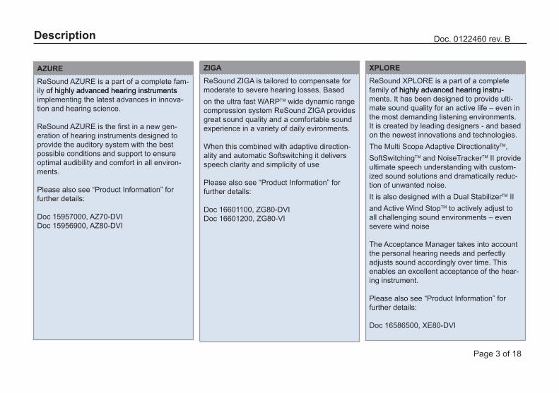
AZUREReSound AZURE is a part of a complete fam-ily of highly advanced hearing instrumentsof highly advanced hearing instruments implementing the latest advances in innova-tion and hearing science.
ReSound AZURE is the first in a new gen-eration of hearing instruments designed to provide the auditory system with the best possible conditions and support to ensure optimal audibility and comfort in all environ-ments.
Please also see “Product Information” for further details:
Doc 15957000, AZ70-DVIDoc 15956900, AZ80-DVI
ZIGAReSound ZIGA is tailored to compensate for moderate to severe hearing losses. Based on the ultra fast WARPTM wide dynamic range compression system ReSound ZIGA provides great sound quality and a comfortable sound experience in a variety of daily evironments.
When this combined with adaptive direction-ality and automatic Softswitching it delivers speech clarity and simplicity of use
Please also see “Product Information” for further details:
Doc 16601100, ZG80-DVIDoc 16601200, ZG80-VI
XPLOREReSound XPLORE is a part of a complete family of highly advanced hearing instru-of highly advanced hearing instru-ments. It has been designed to provide ulti-mate sound quality for an active life – even in the most demanding listening environments. It is created by leading designers - and based on the newest innovations and technologies.The Multi Scope Adaptive DirectionalityTM, SoftSwitchingTM and NoiseTrackerTM II provide ultimate speech understanding with custom-ized sound solutions and dramatically reduc-tion of unwanted noise.It is also designed with a Dual StabilizerTM II and Active Wind StopTM to actively adjust to all challenging sound environments – even severe wind noise
The Acceptance Manager takes into account the personal hearing needs and perfectly adjusts sound accordingly over time. This enables an excellent acceptance of the hear-ing instrument.
Please also see “Product Information” for further details:
Doc 16586500, XE80-DVI
Page 4 of 18
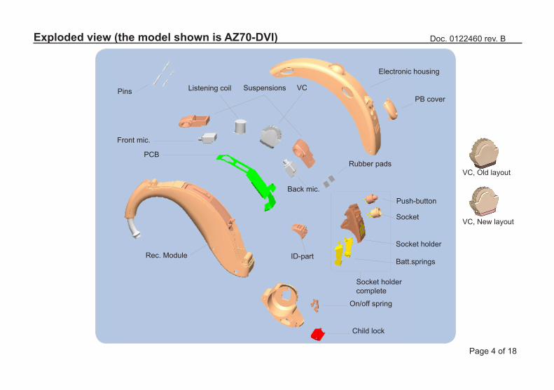
Doc. 0122460 rev. BExploded view (the model shown is AZ70-DVI)
PCB
Front mic.
Back mic.
SuspensionsPins Listening coil VC
Rubber pads
Batt.springs
Socket
Push-button
Socket holdercomplete
Socket holderID-partRec. Module
Electronic housing
PB cover
On/off spring
Child lock
VC, New layout
VC, Old layout
Page 5 of 18
Doc. 0122460 rev. B
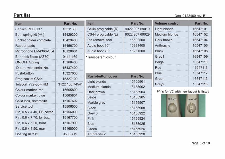
Item Part No.Service PCB C3.1 16311300Batt. spring kit (+/-) 15429300Socket holder complete 15429400Rubber pads 15456700Microphone EM4368-C54 10128601Ear hook filters (AZ70) 0414-469ON/OFF Spring 15168400ID part, with serial No. 15437400Push-button 15327000Prog socket CS44 15327100Telecoil Y29-36-FHM 3122 150 74541Colour marker, red 15665800Colour marker, blue 15665801Child lock, anthracite 15167602Service tool 15506500Pin, 0.5 x 4.40, PB cover 15156000Pin, 0.6 x 7.70, for batt. 15167700Pin, 0.6 x 5.20, front 15167900Pin, 0.6 x 8.50, rear 15168000Coating KR112 9500-719
Part listItem Part No.CS44 prog cable (R) 9022 907 69019CS44 prog cable (L) 9022 907 69029Pin removal tool 15502500Audio boot 80* 16231400Audio boot 70* 16231500
Volume control Part No.Light blonde 16547101Medium blonde 16547102Dark brown 16547104Anthracite 16547106Black 16547108Grey1 16547109Beige 16547110Red 16547111Blue 16547112Green 16547113Grey2 16547115
Push-button cover Part No.Light blonde 15155901Medium blonde 15155902Dark brown 15155904Beige 15155905Marble grey 15155907Black 15155908Grey 3 15155922Pink 15155924Blue 15155925Green 15155926Anthracite 2 15155928
P/n’s for VC with new layout is listed
New VCOld VC
*Transparent colour

Page 6 of 18
Doc. 0122460 rev. B
Battery door70 models 80 models
Light blonde 15441701 15555401Medium blonde 15441702 15555402Dark brown 15441704 15555404Beige 15441705 15555405Marble grey 15441707 15555407Black 15441708 15555408Grey 3 - 15555422Pink - 15555424Blue - 15555425Green - 15555426Anthracite 2 - 15555428Metallic - 16107610
Microphone suspensionFront Back
Light blonde 15155101 15155301Medium blonde 15155102 15155302Dark brown 15155104 15155304Beige 15155105 15155305Anthracite 2 15155106 15155306Black 15155108 15155308Marble grey 15155109 15155309Red 15155111 15155311Blue 15155112 15155312Green 15155113 15155313Grey2 15155115 15155315
Part list

Page 7 of 18
Doc. 0122460 rev. BPart list, HSG parts AZURE
* Receiver module includes housing, hook, receiver and wires and must always be ordered if the receiver is defective
Receiver Module*AZ70-DVI AZ80-DVI
Light blonde 16311101 16311201Medium blonde 16311102 16311202
Dark brown 16311104 16311204Beige 16311105 16311205
Marble grey 16311107 16311207Black 16311108 16311208
Metalic - 16311210Grey 3 - 16311222Pink - 16311224Blue - 16311225
Green - 16311226Anthracite 2 - 16311228
Electronic housingAZ70-DVI AZ80-DVI
Light blonde 15145201 15145201Medium blonde 15145202 15145202
Dark brown 15145204 15145204Beige 15145205 15145205
Marble grey 15145207 15145207Black 15145208 15145208Pink - 15145224Blue - 15145225
Green - 15145226Anthracite 2 - 15145228
Metalic - 16107911

Page 8 of 18
Doc. 0122460 rev. BPart list, HSG parts ZIGA
* Receiver module includes housing, hook, receiver and wires and must always be ordered if the receiver is defective
Electronic housingZG80-VI ZG80-DVI
Light blonde 15559201 15145201Medium blonde 15559202 15145202
Dark brown - 15145204Beige 15559205 15145205
Marble grey - 15145207Black - 15145208Pink - 15145224Blue - 15145225
Green - 15145226Anthracite 2 - 15145228
Metalic - 16107911
Receiver Module*ZG80-VI ZG80-DVI
Light blonde 16679401 16679301Medium blonde 16679402 16679302
Dark brown - 16679304Beige 16679405 16679305
Marble grey - 16679307Black - 16679308
Metalic - 16679310Grey - 16679322Pink - 16679324Blue - 16679325
Green - 16679326Anthracite 2 - 16679328
Page 9 of 18
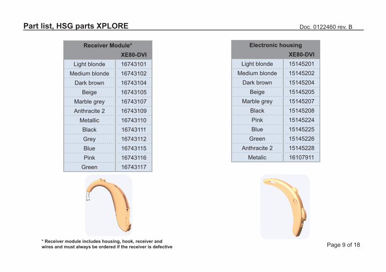
Doc. 0122460 rev. BPart list, HSG parts XPLORE
* Receiver module includes housing, hook, receiver and wires and must always be ordered if the receiver is defective
Electronic housingXE80-DVI
Light blonde 15145201Medium blonde 15145202
Dark brown 15145204Beige 15145205
Marble grey 15145207Black 15145208Pink 15145224Blue 15145225
Green 15145226Anthracite 2 15145228
Metalic 16107911
Receiver Module*XE80-DVI
Light blonde 16743101Medium blonde 16743102
Dark brown 16743104Beige 16743105
Marble grey 16743107Anthracite 2 16743109
Metallic 16743110Black 16743111Grey 16743112Blue 16743115Pink 16743116
Green 16743117
Page 10 of 18
Doc. 0122460 rev. B
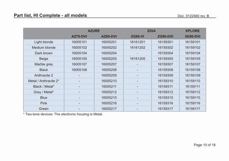
* Two-tone devices: The electronic housing is Metal.
AZURE ZIGA XPLOREAZ70-DVI AZ80-DVI ZG80-VI ZG80-DVI XE80-DVI
Light blonde 16005101 16005201 16161201 16159301 16159101Medium blonde 16005102 16005202 16161202 16159302 16159102
Dark brown 16005104 16005204 - 16159304 16159104Beige 16005105 16005205 16161205 16159305 16159105
Marble grey 16005107 16005207 - 16159307 16159107Black 16005108 16005208 - 16159308 16159108
Anthracite 2 - 16005209 - 16159309 16159109Metal / Anthracite 2* - 16005210 - 16159310 16159110
Black / Metal* - 16005211 - 16159311 16159111Grey / Metal* - 16005212 - 16159312 16159112
Blue - 16005215 - 16159315 16159115Pink - 16005216 - 16159316 16159116
Green - 16005217 - 16159317 16159117
Part list, HI Complete - all models
Page 11 of 18
Doc. 0122460 rev. B
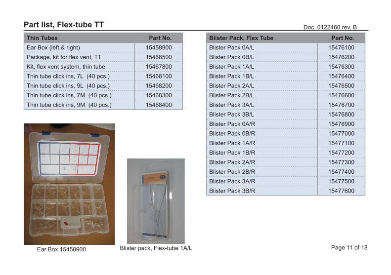
Blister Pack, Flex Tube Part No.Blister Pack 0A/L 15476100Blister Pack 0B/L 15476200Blister Pack 1A/L 15476300Blister Pack 1B/L 15476400Blister Pack 2A/L 15476500Blister Pack 2B/L 15476600Blister Pack 3A/L 15476700Blister Pack 3B/L 15476800Blister Pack 0A/R 15476900Blister Pack 0B/R 15477000Blister Pack 1A/R 15477100Blister Pack 1B/R 15477200Blister Pack 2A/R 15477300Blister Pack 2B/R 15477400Blister Pack 3A/R 15477500Blister Pack 3B/R 15477600
Thin Tubes Part No.Ear Box (left & right) 15458900Package, kit for flex vent, TT 15468500Kit, flex vent system, thin tube 15467800Thin tube click ins, 7L (40 pcs.) 15468100Thin tube click ins, 9L (40 pcs.) 15468200Thin tube click ins, 7M (40 pcs.) 15468300Thin tube click ins, 9M (40 pcs.) 15468400
Part list, Flex-tube TT
Ear Box 15458900 Blister pack, Flex-tube 1A/L
Page 12 of 18
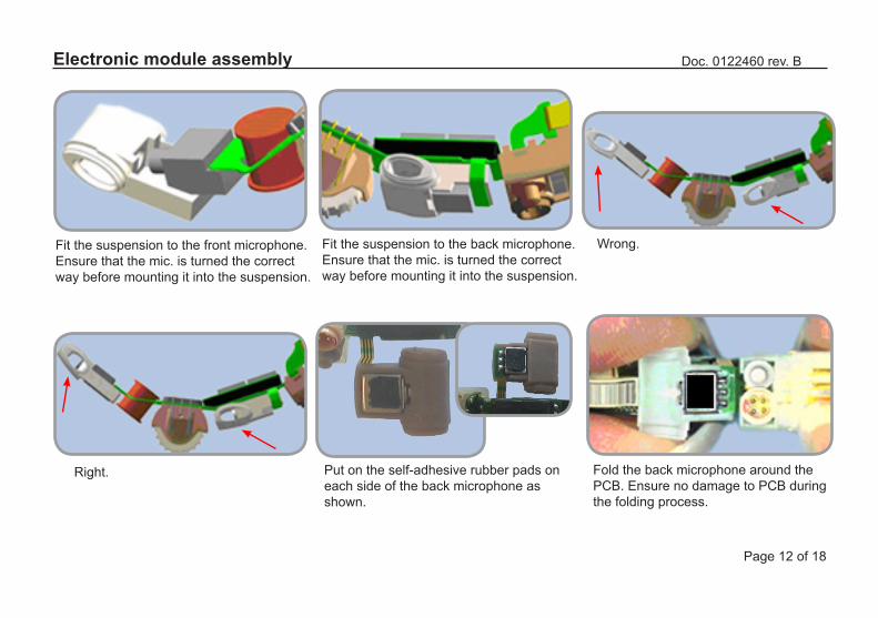
Doc. 0122460 rev. BElectronic module assembly
Right.
Fit the suspension to the front microphone.Ensure that the mic. is turned the correct way before mounting it into the suspension.
Fit the suspension to the back microphone.Ensure that the mic. is turned the correct way before mounting it into the suspension.
Wrong.
Fold the back microphone around thePCB. Ensure no damage to PCB duringthe folding process.
Put on the self-adhesive rubber pads oneach side of the back microphone as shown.
PICTURE

Page 13 of 18
Doc. 0122460 rev. BElectronic module assembly
Align the keys on the socket holder with the grooves in the housing. Press the amplifier gently into theElectronic module housing.
Adjust the mic. suspensions to ensure They are correctly seated in the elec-tronic housing.
Place the PB cover + hinge(0.5x4.40) on the housing.
Ensure no damage to the cover dur-ing the insertion process.
Electronic module complete.
Page 14 of 18
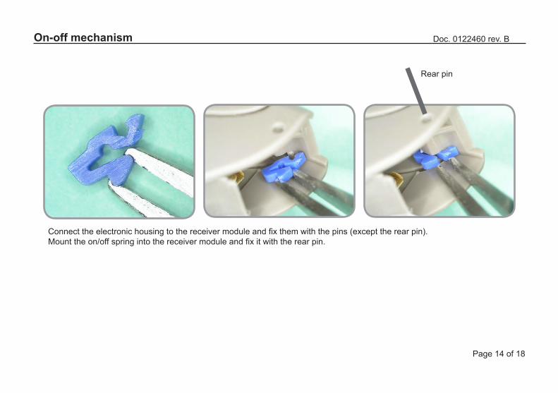
Doc. 0122460 rev. BOn-off mechanism
Connect the electronic housing to the receiver module and fix them with the pins (except the rear pin). Mount the on/off spring into the receiver module and fix it with the rear pin.
Rear pin
Page 15 of 18
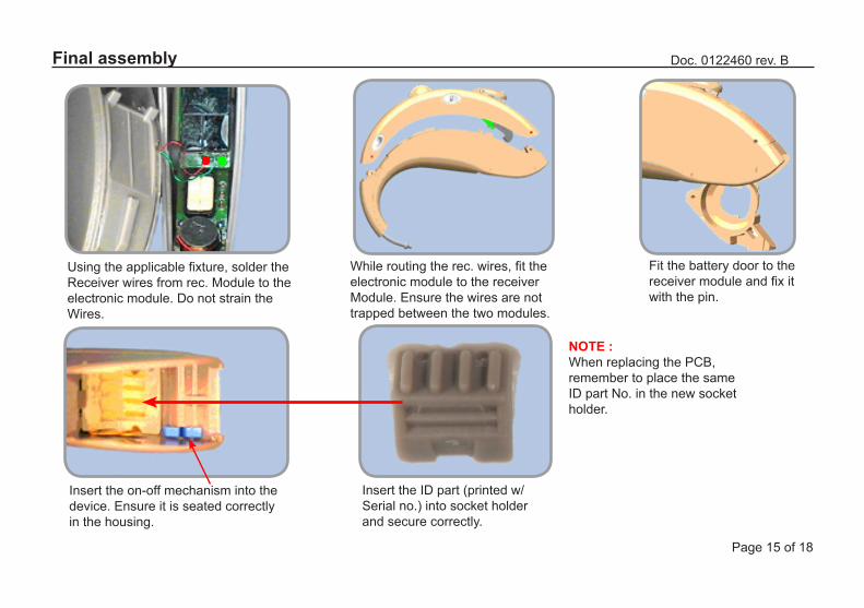
Doc. 0122460 rev. BFinal assembly
NOTE :When replacing the PCB,remember to place the sameID part No. in the new socketholder.
Using the applicable fixture, solder theReceiver wires from rec. Module to the electronic module. Do not strain theWires.
While routing the rec. wires, fit the electronic module to the receiverModule. Ensure the wires are not trapped between the two modules.
Fit the battery door to the receiver module and fix it with the pin.
Insert the on-off mechanism into the device. Ensure it is seated correctly in the housing.
Insert the ID part (printed w/Serial no.) into socket holder and secure correctly.
Page 16 of 18
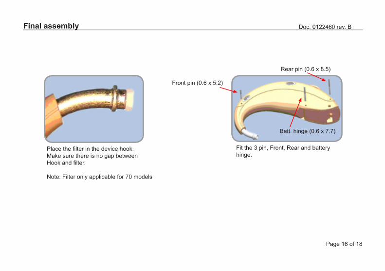
Doc. 0122460 rev. BFinal assembly
Place the filter in the device hook.Make sure there is no gap betweenHook and filter.
Note: Filter only applicable for 70 models
Rear pin (0.6 x 8.5)
Fit the 3 pin, Front, Rear and battery hinge.
Front pin (0.6 x 5.2)
Batt. hinge (0.6 x 7.7)
Page 17 of 18
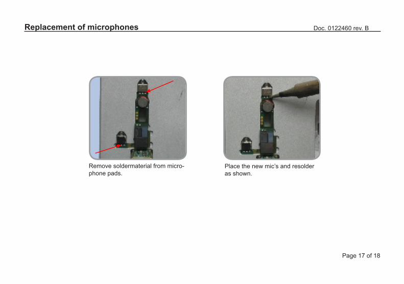
Doc. 0122460 rev. BReplacement of microphones
Remove soldermaterial from micro-phone pads.
Place the new mic’s and resolderas shown.
Page 18 of 18
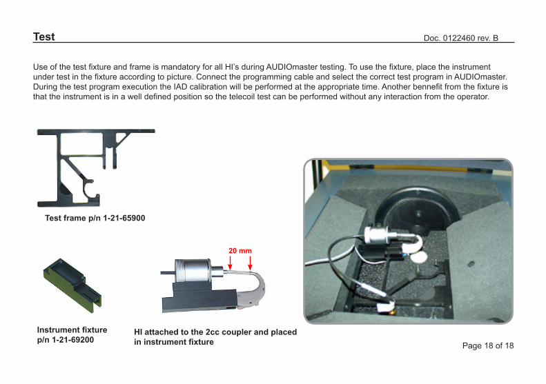
Doc. 0122460 rev. BTest
Use of the test fixture and frame is mandatory for all HI’s during AUDIOmaster testing. To use the fixture, place the instrument under test in the fixture according to picture. Connect the programming cable and select the correct test program in AUDIOmaster. During the test program execution the IAD calibration will be performed at the appropriate time. Another bennefit from the fixture is that the instrument is in a well defined position so the telecoil test can be performed without any interaction from the operator.
20 mm
HI attached to the 2cc coupler and placed in instrument fixture
Instrument fixture p/n 1-21-69200
Test frame p/n 1-21-65900