axiograp h iii - sam-dental home · the axiograph® is a diagnostic instrument which can emulate...
TRANSCRIPT

A XIOGR APH® IIIMANUAL
AXIOGRAPH® PROCEDURES MANUAL
by
Carl G. Wirth, O.D.S.- Heinz K. Mack - Dr. Hans-Henning Ohlrogge
The AXIOGRAPH® is a diagnostic instrument which can emulate condylar movement pathways. The procedure is called AXIOGRAPHY. The resultant graphic output is called an AXIOGRAM.
The AXIOGRAPH® III system, in contrast with pantographic recording systems, uses only two recording styli in a collinear alignment and rectilinear with the upper AXIOMATIC® flag bow recording plates. The new AXIOMATIC® combination flag/facebow positions the two lower recording styli automatically on a collinear predetermined hinge axis reference point anatomically related to the center of rotation of both condyles. This new alignment system allows the operator to record mandibular movements without first having to determine the precise hinge axis position. The AXfOGRAMS having the highest fidelity and can be used for direct interpretation, clinical diagnosis and treatment planning. in addition, the AXIOGRAMS do not contain the artifacts normally present in non-collinear recording systems or the errors which are often occur as a result of the hinge axis determination procedures.
OTHER AXIOGRAPH@ FEATURES:
1. The system is easy to use. and can be attached to the patient within 10 minutes 2. Automatic predetermined hinge axis is within clinical norm. 3. Automatic predetermined anterior reference point is related to Nasion and Orbitale. 4. Recordings are not affected by vertical dimension changes. 5. Functional condylar movement pathways can be recorded and analyzed. 6. Dysfunctional condylar movement pathways can be recorded and analyzed. 7. Bennett movement and side-shift can be recorded and measured. 8. Condylar displacement can be recorded and measured. 9. Hinge Axis facebow transfer is made with the maxillary flag/facebow. 10. Anatomic facebow transfer is automatically included in Hinge Axis facebow transfer. 11. Multiple facebow transfers can be made with one maxillary flagbow. 12. Lower flagbow can be aligned collinear after precise Hinge Axis location. 13. AXIOGRAM data can be used with AXIOCOMp® computer program. 14. AXIOGRAM data can be used to program articulators. 15. AXIOTRON® (Electronic AXIOGRAPH@) is easily attached in a few minutes.
2

AXO 500 AXIOGRAPH® III
Complete AXIOGRAPH® Recording Instrumentation. Contents: Aluminum Carry Case with formed inserts for upper and lower equipment:
AXIOMATIC®Combination Flag/Facebow System Complete Lower Recording Bow Complete Measuring instruments . Data and Conversion Charts

AXIOGRAPH® III PROCEDURES:
Additional Equipment and Materials Needed:
Impression Plaster (Kerr #2) Small Plaster Mixing Bowl and Spatula for Impression Plaster Rubber Plaster Mixing Bowl for Head Rest (large) Strip of Red or White Soft Rope Wax for Tray Clutch Putty Silicone Impression Material for Nasion Relator Red Stick Impression Compound (Kerr, GC) for
Facebow Transfer Fork Flexible Masking Tape (19mm wide) for Facebow Transfer Fork
(Tesa 5250) for drawing and art work Alcohol Lamp Water 8ath Magnifying Loupes (Optional)
FACEBOW TRANSFER FORK PREPARATION (AXO 460)
1. Cut two 7 cm strips of flexible masking tape (19 mm wide). Starting just behind the SAM® engraving on the bottom side of the fork, place the cut tape edge to just cover the hole in the fork and proceed distally to cover the second hole and the top side of the facebow transfer fork. Continue over the posterior edge of fork and then anteriorally, applying the rest of the tape to the corresponding top surface of the fork covering the two exposed holes on the top side. Repeat procedure on the opposite side of the facebow transfer fork using second 7 cm strip of flexible masking tape.
2. Cut one 3.5 cm strip of flexible masking tape. Starting just behind the round elevation on the bottom side of the fork, place the cut tape edge to just cover the hole in the fork and proceed distally and anteriorally onto the top surface of the fork, again covering the hole and extending forward to end on top of the straight rod.
3. Heat impression compound in an alcohol flame until it begins to flow. Place a mound of flowing impression compound, approximately 1.5 cm in diameter, onto the top surface of the facebow transfer fork in the anterior teeth area and in the left and right most posterior tooth contacting areas. Place in a warm water bath to temper.
4. Place facebow transfer fork in the patient, align front rod under the nose, and obtain tooth imprints in the softened compound. Remove transfer fork and check imprints. Replace in the mouth and hold in position until impression compound is hard.
5. Place a mound of flowing impression compound onto the lower surface of the facebow transfer fork in both premolar areas. Place in a water bath to temper.
6. Replace facebow transfer fork against patient's upper teeth fitting into previously made imprints, have patient close lightly into the soft compound on the lower side of the facebow transfer fork. Allow impression compound to harden.
4
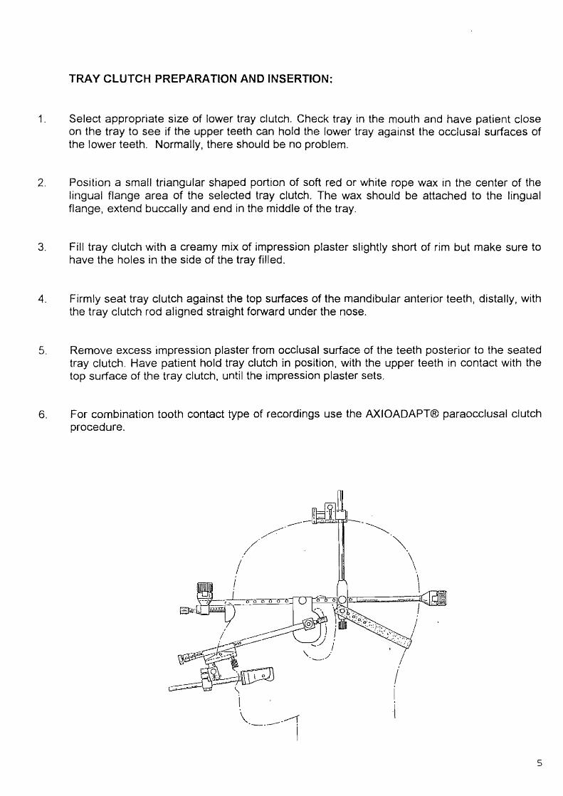
TRAY CLUTCH PREPARATION AND INSERTION:
1. Select appropriate size of lower tray clutch. Check tray in the mouth and have patient close on the tray to see jf the upper teeth can hold the lower tray against the occlusal surfaces of the lower teeth. Normally, there should be no problem.
2. Position a small triangular shaped portion of soft red or white rope wax in the center of the lingual flange area of the selected tray clutch. The wax should be attached to the lingual flange, extend buccally and end in the middle of the tray.
3. Fill tray clutch with a creamy mix of impression plaster slightly short of rim but make sure to have the holes in the side of the tray filled.
4. Firmly seat tray clutch against the top surfaces of the mandibular anterior teeth, distally, with the tray clutch rod aligned straight forward under the nose.
5. Remove excess impression plaster from occlusal surface of the teeth posterior to the seated tray clutch. Have patient hold tray clutch in position, with the upper teeth in contact with the top surface of the tray clutch, until the impression plaster sets.
6. For combination tooth contact type of recordings use the AXIOADAPT® paraocclusal clutch procedure.
/
,~~""06 Gil!ilJ~ .
/
5

AXIOMATIC® FACE/FLAG BOW PREPARATION:
AXIOMATIC® NASION RELATOR:
1. Loosen thumb nut cap #2 of Nasion Relator #1 and remove Nasion Relator #1 from upper anterior flag bow cross rod #3.
2. Make a silicone putty cushion for the patient's Nasion by adapting a small amount of silicone putty to the curved surface of the Black Nose Piece of Nasion Relator #1.
3. Position the prepared Nasion Relator #1 perpendicular to the Nasion and parallel to the Axis-Orbital Plane. Silicone material should cover the front curved surface of the Black Nose Piece of the Nasion Relator #1 and extend over the top and bottom surface onto the flat back surface of the Nasion Relator #1 for a holding effect. Remove excess silicone from the flat sides of the Nasion Relator #1.
4. Retract the thumb screw of Nasion Relator #1 to the most anterior position.
5. Reattach Nasion Relator #1 to the center of front rod #3 in between the two red depressions.
AXJOMATIC® EARPIECE ALIGNMENT FLAG ATTACHMENT:
1. Place Blue Hygienic Earpiece Caps (ATB 240) on the left and right AXIOMATIC® earpiece alignment flags #10 and #11.
2. Periodically, lubricate the O-rings of the AXIOMATIC® lower sidearm horizontal extension rods #20 with a small amount of Vaseline. Check for a smooth functional fit of the horizontal extension rods #20 in the AXIOMATIC® reference measurement alignment gauge sliding tube assemblies #23.
3. Loosen thumb nut caps #22 of the sliding tube assemblies #23 of the AXIOMATIC® reference measurement alignment gauge #21. Move the loosened sliding tube assemblies #23 to their extreme lateral position and retighten the thumb nut caps #22. If working from the right side of the patient, attach AXIOMATIC® earpiece alignment flag #11 to one of the repositioned sliding tube assemblies #23 of the AXIOMA TIC® reference measurement alignment gauge #21 by placing the lower facebow axis alignment pin #12, which is on the outer side of the earpiece, into the hole in the sliding tube assembly #23. If the facebow axis alignment pin #12 is difficult to insert into the hole of the sliding tube assembly #23, slight pressure and repeated insertion and removal will give the correct fit
4. Attach one AXIOMATIC® sidearm horizontal extension rod #20 to the hole in the sliding tube assembly #23 on the other side of the AXIOMATIC® reference alignment gauge #21.
6
5. Place the AXIOMATIC® earpiece alignment flag #11 into the appropriate external auditory meatus with the top flat surface of the earpiece alignment flag #11 parallel to the Axis Orbital Plane. Loosen the opposite side thumb nut cap #22 and position the AXIOMATIC® reference measurement alignment gauge #21 with sliding tube assembly #23 which contains the horizontal extension rod #20, distally! to rest on the Nasion of the patient The horizontal extension rod #20 should be paranel to the front of the face. Tighten thumb nut cap #22 and remove the assembly from the patient.
6. With the tOf of the AXIOMATIC® earpiece alignment flag #11 held parallel to the AXIOMATIC reference alignment gauge rod #21 , position the AXIOMATIC® earpiece alignment flag #11 earpiece tip against the middle of the outside edge of the left side of the AXIOMATIC® flag bow front rod #3. Align the AXIOMATJC® reference alignment gauge #21 paranel to the left flagbow sidearm #6.
7. Place the AXIOMATIC® horizontal extension rod #20 on top of the AXIOMATIC® flag bow sidearm #6 and identify the screw hole of the flag sidearm closest to the horizontal extension rod and most anterior. Move the sidearm flag attachment screw #15 to the new screw hole position, if needed. Move opposite side recording flag attachment screw #15 to the same identical screw hole position.
8. Attach left and right AXIOMATIC® earpiece alignment flags #10 and #11 to the AXIOMATfC® facebow sidearms #6 and #9 with screws #15. Tighten firmly in place.
9. Loosen left and right sidearm thumb nut caps #7 and move sidearms #6 and #7 laterally.
10. With patient sitting upright in the dental chair, head out of contact with the head rest, have patient support the AXIOMATIC® flag bow sidearms #6and #9 with the thumb and two fingers of each hand on both AXrOMATIC® earpiece alignment flags #10 and #11.
11 . Move the AXIOMA TIC® sidearms #6 and #9 mediaHy, equidistant, until earpieces are seated in the external auditory meatus. Instruct patient to follow the AXIOMATIC® earpiece alignment flags #10 and #11 to position without applying inward pressure.
12. Position the Nasion Relator #1, just short of touching the Nasion. There should be less then 1 centimeter of screw threads between the black Nasion Relator nose piece and the upper front rod #3. If distance is greater than 1 em, remove AXIOMATIC® flagbow assembly from the patient. Retract the Nasion Relator #1, move the AXfOMATIC® earpiece alignment flag screws #15 one screw hole anterior, reattach AXIOMATIC® earpiece alignment flags #10 and #11 and tighten firmly. Record which screw hole was used for attaching the AXIOMATIC® earpiece alignment flags #10 and #11. Starting at the RED dimple, three screw holes are available posteriorally, and are identified as R+1, R+2 and R+3. Anteriorally. they are identified as R-1, R-2 and R-3.
7
ATTACHMENT AND ALIGNMENT OFAXIOMATIC® FLAGBOW ON PATIENT:
1. Attach AXIOMATIC® horizontal side arm extension rods #20 to the posterior end of the AXIOMATIC® flagbow sidearms #6 and #9. Tighten firmly.
2. Attach combination mastoid bone and vertical head support rods #16 to AXIOMATIC® flag bow sidearms #6 and #9 so that three (3) screw holes remain exposed distal to the attached AXIOMATIC® alignment flags #10 and 11 to provide space for the patient's ear. Tighten vertical head support assembly thumb screws #19 firmly. Check that mastoid pins #17 are positioned laterally and mastoid pin holding screws #18 are tightened firmly.
3. Loosen feft and right sidearm thumb nut caps #7 and move sidearms #6 and #9 laterally.
4. With patient sitting upright in the dental chair, head out of contact with the head rest, have patient support the AXIOMATIC® flag bow sidearms #6and #9 with the thumb and two fingers of each hand on both AXIOMA TIC® earpiece alignment flags #10 and #11. Move the AXIOMATIC® sidearms #6 and #9 medially, equidistant, until earpieces are seated in the external auditory meatus. Instruct patient to follow the AXIOMATIC® earpiece alignment flags #6 and #9 to position in the external auditory meatij WITHOUT inward pressure until hearing is blocked. Make an Initial adjustment of the Nasion Relator #1 just short of contact.
5. Once AXIOMATIC® earpiece alignment flags #6 and #9 are seated in position, have patient hold earpiece alignment flags #6 and #9 in an upward position firmly against the superior wall of the external auditory meatii and with light inward pressure.
6. Carefully measure the distance between the left and right posterior horizontal extension rods #20 using the sliding tube assembly holes #23 of the AXIOMATIC® reference measurement alignment gauge #21. Move one sliding tube assembly #23 to the extreme lateral position and lock in place and loosen the thumb nut cap #22 of the opposite sliding tube assembly #23. Position open end of the sliding tube assembly #23, which is fixed, to a 45 degree angle to the beveled end of one horizontal extension rod #20. Move opposite sliding tube assembly #23 so that the opening aligns with the beveled end of the opposite horizontal extension rod #20. This measures the distance between the two sliding tube assembly holes #23 of the AXIOMATIC® reference measurement alignment gauge #21. Lock the loosened thumb nut cap #22 at the measured distance.
7. Compare the posterior measurement with the distance between left and right thumb nut caps #7 on the anterior end of sidearms #6 and #9. Invert the AXIOMATIC® reference measurement alignment gauge #21 so that the thumb nut caps #22 are in contact with the sidearm #6 and #9 thumb nut caps #7. Align left thumb nut cap #22 with thumb nut cap #7 on one side and check the difference in width between the thumb nut cap #22 and thumb nut cap #7 on the right side.
8. Note the millimeter readings on both sides of the anterior crossrod #3. Adjust the anterior crossrod side which will tend to make both sidearms #6 and #9 equidistant from the midline. Increase or decrease the distance between the left and right thumb nut caps #7 by approximately 50 0
/0 of the measured posterior difference. Retighten thumb nut caps #7 on the sidearm rods #6 and #9.
9. Repeat procedure as described in 6-9 above until anterior and posterior measured distances are identical and the AXIOMATIC® reference measurement alignment gauge #21 thumb nut assembly #23 holes fit the horizontal extension rods #20 without friction or binding. Make sure both thumb nut caps #7 and #22 are tightened.
8

10. Verify that screws # 19 of the combination mastoid bone and vertical support rods #16 are tight on sidearms #6 and #9. Measure the distance between left and right combination vertical rods with AXIOMATIC® reference measurement alignment gauge #21. The distance between the outside edges of the small tapered portion of the top of the combination vertical rods should be approximately the same as the distance between the vertical lines on the anterior lateral side of the sidearm front rod attachment assembly assemblies #8. If all thumb screws and caps have been tightened, the measurement will usually be correct. If not, combination mastoid bone and vertical support rod attachment screws #19, anterior sidearm thumb nut caps #7 or horizontal extension rods may be loose. Correct as necessary and recheck measurement.
11. Attach sliding tube assembly #23 holes of the AXIOMATIC® reference measurement alignment gauge #21 onto the horizontal extension rods #20 and snap in place.
12. The AXIOMATIC® flagbow anterior rod #3 must be set parallel to the pupils of the eyes. This is accomplished in the next few steps.
13. Attach the AXIOMATIC® vertical head support #25 to combination mastoid bone vertical support rods #16, first have the patient hold AXIOMATIC® earpiece alignment flags #10 and #11 firmly upwards and seated in the external auditory meatii. Next hold large thumb screws #26 of vertical head support #25 and position the head pad on the cranium. Tighten vertical head support clamps #27 by tightening thumb screws #26 without moving combination vertical support rods #16 inward. At the same time, exert a slight upward pressure on each combination vertical support rod #16 to obtain a firm contact between the cranium and vertical head support #25. In addition, check the alignment of the pupils of the eyes with the AXIOMATIC® flagbow anterior rod #3 and adjust either the left or right vertical support rods #16 to produce the parallel alignment.
Slide Mastoid bone support pins #17 to position and tighten thumb screws #18 firmly. Repeat on opposite side
14. Make sure Nasion Relator thumb nut cap #2 is tight and finalize positioning of the Black Nosepiece of the Nasion Relator #1 in contact with the Nasion of the patient.
15. Attach rubber band #24 to left Mastoid bone support pin #17. Position the rubber band below the hair line, across the nape of the neck and then attach to the right Mastoid bone support pin #17.
16. Check that the AXIOMATIC® flagbow assembly is firmly in position on the cranium.
17. Carefully remove as one intact unit, the AXIOMATIC® reference alignment gauge #21 together with both horizontal sidearm extension rods #20. Unscrew both horizontal extension rods #20 simultaneously until the AXIOMATIC® reference alignment gauge #21 and the horizontal extensions rods #20 are removed intact, as a unitt from the posterior end of the AXIOMATIC® flagbow sidearms #6 and #9. DO NOT LOOSEN Thumb Nut Caps #22 of the AXIOMATIC® reference alignment gauge #21 because the recorded measurement is used later for the lower AXIOGRAPH® facebow attachment procedure.
18. Place a large rubber bowl or similar type of support on the head rest of the dental chair and on the back of the patient's head. This is to keep the posterior ends of the side arms #6 and #9 of the AXIOMATIC® Face Bow free from contact with the dental chair or head rest.
9
ATTACHMENT AND ALIGNMENT OFAXIOGRAPH® LOWER RECORDING BOW:
1. Prepare AXIOGRAPH® lower recording bow by realigning both sidearms #30 and #31 sagittally, vertically and equidistant.
2. Attach AXIOGRAPH® lower recording bow alignment tubes #36 to both sidearms #30 and #31.
3. Position AXIOMATIC® reference alignment gauge #21 on the table with the thumb nut caps #22 upside down on the table surface.
4. Loosen AXIOGRAPH® lower recording bow sidearms #30 and #31. Place the AXIOGRAPH® lower recording bow alignment tubes #36 in position into the specially cut depressions on the flat outside surface ofAXIOMATIC® reference alignment gauge sliding tube assemblies #23. Keep sidearms #30 and #31 upper surfaces parallel to the table top. Tighten sidearm bar clamps #32. After adjustment, the AXIOGRAPH® lower recording bow sidearms #30 and #31 should be checked on the table top and both sidearms #30 and #31 should remain flat on the table top.
5. Recheck lower tray clutch #48 for tightness and excess plaster. Correct as necessary.
6. Retract the right AXIOGRAPH® lower recordin~ bow axis alignment tube #36 and lightly tighten retaining screw #35. Attach AXIOGRAPH lower recording bow to tray clutch rod with the SAM® NT Universal clamp #37 positioned on the front rod loosely and with the bar clamp positioned downward.
7. Place the left axis alignment tube #36 into position onto the axis alignment pin #12 on the outer surface of the AXIOMATIC® earpiece alignment flag #10, guide right retracted axis alignment tube #36 to position over the right AXIOMATIC® earpiece axis alignment pin #12, loosen thumb screw #35, move axis alignment tube to full seated position and lock in place. The axis alignment tubes #36 should be fully seated and in contact with the AXIOMATIC® earpiece alignment flags #10 and #11.
8. Place patient in Centric Relation Reference Position, make sure lower AXIOGRAPH® anterior rod #28 and rod of tray clutch #48 are free to move in the SAM® NT Universal Clamp #37. Tighten SAM® NT Universal Clamp #37.
9. Loosen thumbscrews #35 and check both AXIOMATIC® axis alignment tubes #36 for proper alignment. The AXIOGRAPH® lower recording bow sidearms #30 and #31, the AXtOGRAPH® axis alignment pins #12 and the AXIOGRAPH® axis alignment tubes #36 should be collinear. The AXIOGRAPH® lower recording bow is properly positioned and aligned when the AXIOGRAPH® axis alignment tubes #36 can slide on and off the AXIOGRAPH® axis alignment pins #12 with minimal contact.
10
AXIOGRAPH RECORDINGS:
INITIAL PREPARATION:
1 . lightly lubricate the outer surface of the AXIOGRAPH® recording flags #13 and #14 with MAT 101 1 SAM® Special Aluminum Lubricant. Use a small amount of lubricant on the plate and wipe on the outside surface which will receive the recording graph paper. Remove excess lubricant. NOTE: SAM® lubricant should not come in contact with any rods that will be used with any clamps because it will be very difficult to lock clamps on the rods due to the extreme lubricating qualities of MAT 101.
2. Place recording graph paper, AXO 111, on AXIOGRAPH® recording flags #13 and #14.
3. Remove both AXfOMATIC® ear~iece alignment flags #10 and #11 and replace with previously prepared AXfOGRAPH recording ffags #13 and #14.
4. Approximately 2 mm of fead should protrude from the lead holder of the dial gauge #41 or yellow recording device #46. Carefully sharpen the read by holding the lead holder in one hand, place the lead in contact with the fine surface of the diamond fire, move file forward and back and at the same time rotate the lead holder until a sharp tip is formed.
RECORDING REFERENCE POSITION:
® All AXIOGRAPH recordings should have a transverse horizontal reference point related to the center of rotation of the mandibular condyfes and a third anterior reference point such as Orbitale.
The new AXIOGRAPH® alignment procedure, using the AXIOMATIC® combination upper flag/facebow, provides the operator with an anatomically related predetermined hinge axis position of the AXIOGRAPH® lower recording bow styli automatically upon completion of the AXIOGRAPH® setup along with a predetermined anterior reference point related to the Nasion of the patient and Orbitale.
The AXIOGRAMS, produced with the predetermined reference points, have all of the necessary diagnostic information and therefore, it not necessary to find the exact hinge axis or select an individualized anterior reference point unless this is your choice.
In all AXIOGRAPH® recording procedures, it is recommended that an initial set of test and recordings be made prior to making the final recordings. This procedure is invaluable because it gives you a quick overview and an initial diagnosis of the mandibular movement patterns of the patient.
NOTE: If desired, you can determine the exact hinge axis and realign the lower recording bow styli to the newly determined hinge axis position. Also, you can select your own anterior third reference point such as Orbitale, etc.
11
AXIOGRAPH® INITIAL TEST RECORDING PROCEDURES:
1. Cover recording flags #13 and #14 with yellow self stick note paper.
2. Seat the yellow recording device #46 into the left or right sidearm #30 until seated firmly in place and tighten holding screw #35.
3. Record straight protrusive, retract recording lead and have patient return to reference position.
4. Record mediotrusive movement, retract recording lead and have patient return to reference position.
5. Move yellow self stick note paper to a new position. Record a pure hinge axis movement with light chin point guidance or as desired. Retract recording lead.
6. Move yellow self stick note paper to a new position. Record opening and closing movement. Retract recording lead.
7. Loosen thumb screw #35 and remove yellow recording device #46. Insert dial gauge #41 and tighten thumb screw #35. Move yellow self stick note paper to a new position. Have patient make repeated mediotrusion and then media-retrusion movements. Observe the dial gauge activity.
Observing the dial gauge activity will allow you to do detect subclinical clicks, dysfunctional Bennett movement pathways, so-called Immediate side-shift and muscle function disorders. The end-result is an quick overview of the TMJ function plus an initial diagnosis.
8. Have patient make protrusive and then retrusive movements. Observe dial gauge. 9. Have patient make opening and then closing movements. Observe the dial gauge. Remove
the yellow self stick note paper.
10. Insert RED housing pin assembly with stylus #43 into lower recording bow sidearm #30. Tighten thumb screw #35.
11. Place a strip of red occlusion foil on the recording flag #13 and place recording pin in contact with RED foil.
12. With light chin point contact, carefully guide the mandible to CentrIc Position, have patient swallow and mark a RED Reference Point (RP) tapping the recording stylus.
13. Remove red marking tape and check RED Reference Position with stylus pin.
14. Repeat above procedures on the opposite side.
12
AXIOGRAPH® FINAL RECORDING PROCEDURE:
1. The minimum number of final recordings made on the millimeter grid are protrusion and mediotrusion movements. Place the yellow recording device #46 in position in the AXIOGRAPH® sidearm #30 with recording lead retracted. Tighten thumbscrew #35.
2. Have patient go to Reference Position, loosen thumb screw of yellow recording device and aI/ow recording lead to contact the recording flag #13.
3. Record protrusive movement, retract recording lead) have patient return to Reference Position.
4. Record mediotrusion movement, retract recording lead, have patient return to Reference Position.
5. Repeat procedure on opposite side.
6. Remove yellow recording device #46 and place a RED transparent millimeter grid (AXO 112) on the AXIOGRAPH® recording. Use the tip of the small diamond file to hold grid and place in position, making sure the first large red line of the grid is on the RED reference point.
7. Place the dial gauge #41 into the recording sidearm and lock in place.
8. Have patient move the mandible to Reference Position, read the dial gauge and record indicated value on Green AXIOGRAPH® Chart (AXO 110). At s=O.
9. Have the patient move into a mediotrusive direction and read the dial gauge values at each millimeter increment starting at 5=1. Record the values in the white blocks to the left of the s number. Normally the values recorded are from 1 to 5 mm and then at 2 to 3 mm increments up to the end of the recording or as many points as you desire.
10. Remove the dial gauge #41 and repeat the same procedure on the opposite side.
11. Attach AXIOMATIC® Orbital Pointer Assembly #51 to left black precision attachment #5 on the front horizontal rod #3 and tighten thumb screw.
IfAXIOMATIC® predetermined Orbitale reference plane is used, remove orbital pointer and sleeve from Orbital pointer assembly #51. Adjust the black part of the SAM® NT Universal Clamp so that the side of the clamp with the hole is above the screw threads of the bar clamp, parallel to the upper side arms and the word SA~ is faCing downwards. Place the bar clamp and black part of the SAM® NT Universal Clamp completely behind and parallel to the front rod #3. Tighten the bar clamp.
12. If you wish to use and record the Orbitale point of the patient, carefully position the orbital pointer tip on the left Orbitale point with your finger on the tip of pointer to protect the eye. Tighten bar clamp and remove the orbital pointer indicator from the orbital pOinter assembly #51.
13. Record anterior crossrod mm readings for the left side on the white area of recording flag #13 and right side value on recording flag #14. Also indicate the R# value and the interflag distance.
13

AxrOTRON® PROCEDURE:
1. Remove AXIOGRAPH® Recording Flag Plates #13 and #14 and replace with left and right XZ recording plates.
2. Attach left and right Y sensors to lower AXIOGRAPH® sidearms.
3. See AXIOTRON® Manual for additional specific instructions.
AXIOMATIC® HINGE AXIS TRANSFER BOW PROCEDURES:
1. loosen SAM® NT Universal Clamp #37 by loosening the bar clamp. Remove lower AXIOGRAPH® recording bow.
2. Remove lower tray clutch #48 and impression plaster.
3. Attach AXIOMATIC® Facebow transfer fork assembly #50 to the right black precision attachment #5 on the front horizontal rod #3. Tighten thumb screw.
4. Place previously prepared facebow transfer fork #49 against the upper teeth of the patient and have patient close to hold the facebow transfer fork in position.
5. Attach SAM® NT Universal Clamp #37 to facebow transfer fork #49.
6. Tighten bar clamp of the SAM® NT Universal Clamp #37 on facebow transfer fork rod #49.
7. Tighten bar clamp on vertical rod of transfer fork assembly.
14
AXIOMATIC® FLAG/FACEBOW REMOVAL:
1. Check that the thumb nut cap screws #7 on the front horizontal rod #3 are tight.
2. Check that left and right front rod measurements are recorded on recording flags #13 and #14 plus the R # values indicating position of recording flags #13 and #14.
3. Remove the rubber band #24 from mastoid bone support pins #17.
4. Loosen both thumb screws #26 on AXIOMATIC® vertical head support assembly #25and remove vertical head support assembly #25 from vertical rods #16.
Loosen the thumb screws #19 which hold the AXIOMATIC® combination mastoid bone and vertical support rods #16 on the left and right sidearms #6 and #9. Remove the vertical support rods #16.
6. Have the patient open the mouth and remove the entire the AXIOMATIC® facebow with transfer fork assembly.
7. Replace orbital pointer in Orbital Pointer Assembly #51.
8. Remove Nasion Relator #1 .
AXIOGRAPH® REFERENCE PLANE MARKING PROCEDURE:
1. Attach AXIOMATIC® Axis Orbital reference plane transfer device #47 to the most anterior screw hole on the inner left side of the AXIOMATIC® facebow sidearms #6.
2. If predetermined Orbital reference plane is used, the AXIOMATrC® Axis Orbital reference plane transfer device # 47 should be in contact with the top surface of the black SAM® NT Universal Bar Clamp (the side opposite the one containing the word SAM® and in the position as described in item #11, page 16, earlier in this manual).
3. If orbital pointer was used to identify the anterior reference point then the AXIOMATIC® Axis Orbital reference plane transfer device #47 bottom edge should be in line with the tip of the orbital pointer.
4. Place AXIOGRAPH® metal ruler #39 top edge on the bottom edge of the AXIOMATIC® Axis Orbital reference plane transfer device #47 and on the RED reference point of the AXIOGRAPH® tracing on recording flags #13 or #14. Mark the reference plane on the AXIOGRAPH® recording using the dial gauge lead as a marker or some other type of fine lead.
15

ATTACHMENT OFAXIOMATIC® FACEBOW TO HINGE AXIS MOUNTING DEVICE:
AXIOMATIC® HINGE AXIS TRANSFER BOW PROCEDURE:
1. Reattach AXIOGRAPH® recording flags #13 and #14 to AXIOMATIC® facebow sidearms #6 and #9 1 if not already in position.
2. Position AXIOGRAPH® hinge axis recording transfer flag ctamp #38 on AXIOGRAPH® recording flag #13 or #14 centering the tapered hinge axis identification hole on the RED hinge axis reference point. Tighten thumb screws of the transfer flag ctamp #38 keeping the transfer ctamp #38 in position.
3. Repeat with opposite side.
4. Reattach left and right posterior horizontal extension rods #20 to posterior end of left and right #6 and #9 upper sidearms.
5. Reattach AXIOMATIC® reference alignment gauge #21, using prerecorded flag distance, to the left and right horizontal extension rods #20.
6. Attach AXIOMATIC® hinge axis transfer bow assembly to SMG 200 hinge axis mounting device by rotating hinge axis mounting device thumb screw upwards until SMG 200 hinge axis alignment pins come into contact with the small holes on the inside surface of the AXIOGRAPH® hinge axis recording transfer flag clamps #38.
7. Position hinge axis mounting device yellow orbital reference plane device in contact with the top surface of the black SAM® NT Universal Bar Clamp if predetermined anterior reference point has been selected or in contact with the removable pin of AXIOM A TIC® orbital pointer assembly #51. Tighten reference plane thumb screw. Adjust hinge axis mounting device upper member vertical position thumb screw until yellow reference plane contacts the flat top surface of the SAM® NT Universal Bar Clamp or the tip of the orbital pointer.
8. Support facebow transfer fork #49 with SMG 215 magnetic telescoping facebow transfer fork support or with SMG 115 acrylic facebow transfer fork support.
16
AXfOMATIC® ANATOMIC FACEBOW TRAN,SFER BOW PROCEDURE:
1. Reattach AXIOMATIC® earpiece aJignment flags #10 and #11 to AXIOMATIC® facebow sidearms #6 and #9.
2. Reattach left and right posterior horizontal extension rods #20.
3. Reattach AXIOMA TIC® reference alignment gauge #21, using prerecorded flag distance, to Jeft and right horizontal extension rods #20.
4. Attach AXIOMATIC® anatomic transfer bow to SMG 200 hinge axis mounting device by rotating hinge axis mounting device thumb screw upwards until SMG 200 hinge axis alignment pins come into contact with the small hole on the inside surface of the AXIOMATfC® earpiece alignment flags #10 and #11 .
5. If AXIOMATIC ® predetermined Orbitale reference plane is used) remove orbital pointer and sleeve from Orbital pointer assembly #51 Adjust the black part of the SAM® NT Universal Clamp so that the side of the clamp with the hore is above the screw threads of the bar damp. parallel to the upper side arms and the word SAM® is facing downwards. Place the black part of SAM® NT Universal Clamp distally at an outward angle of about 45 degrees. Tighten the bar clamp. Position hinge axis mounting device yellow orbital reference plane over the top of the black part of the SAM® NT Universal Clamp. Tighten reference plane thumb screw. Adjust hinge axis mounting device SMG 200 upper member vertical position thumb screw until yeUow reference plane contacts the SAM® NT Universaf Clamp.
If you use the AXrOMATfC® orbital pointer assembly #51 and estabrish your own Orbitale or other third reference point, position hinge axis mounting device yef(ow orbital reference plane in contact with the removable pin ofAXIOMATIC® orbital pointer assembly #51. Tighten reference plane thumb screw. Adjust hinge axis mounting device upper member vertical position thumb screw until yellow reference pJane contacts the orbital pointer.
6. Support facebow transfer fork with SMG 215 magnetic telescoping facebow transfer fork support or with SMG 115 acrylic facebow transfer fork support.
AXIOGRAPH® RECORDING CONVERSIONS:
Conversion ofAXIOGRAPH® data can be done with the optical loupe supplied with the AXIOGRAPH® and with the AXIOCOMp® Program.
17
OPTICAL LOUPE PROCEDURE:
HORIZONTAL CONDYLAR INCLINATION:
1. The horizontal condylar inclination (HCJ) and type of curvature is determined by using the adjustable focus optical loupe #40 supplied with the AXIOGRAPH®. Align the ring in the center of the loupe on the red dot of the tracing on the zero line of the protractor parallel to axis orbital plane of the tracing.
2. Use the curvature selector in the optical loupe to determine the type of condylar pathway curvature. Place the red reference point of the AXIOGRAPH® tracing under the ring at one end of the curvature selector grid line and position the opposite ring of the curvature selector on the AXIOGRAPH® pathway. Select the closest housing curvature type that matches the AXIOGRAPH® tracing curvature.
3. Read the HCI at the 10 mm fine of the AXIOGRAPH® grid and record on the AXIOGRAPH® chart.
BENNETT GUIDANCE CURVATURE SELECTION:
Use AXIOCOMp® Computer Program and Manual.
AXIOTRON® RECORDING CONVERSIONS:
Conversion ofAXIOTRON® data can be done with overlays used directly on the computer screen output and with the AXIOCOMp® Program.
Refer to AXIOTRON® Computer Program and Manual. Refer to AXIOCOMp® Computer Program and Manual.
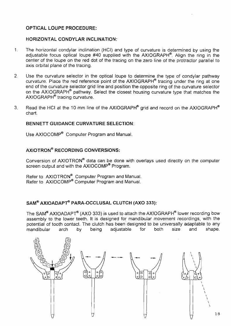
SAM® AXIOADAP~ PARA-OCCLUSAL CLUTCH (AXO 333):
The SAM® AXIOADAP~ (AXO 333) is used to attach the AXIOGRAPH® lower recording bow assembly to the lower teeth. It is designed fo~ mandibular movement recordings, with the potential of tooth contact. The clutch has been designed to be universally adaptable to any mandibular arch by being adjustable for both size and shape.
---
\
\ \
\ \
\
18

PARAOCCLUSAL CLUTCH PROCEDURE:
1 If you have articulator mounted casts goto item 2 else goto 9. 2. Make alginate impression of upper and lower teeth. 3. Pour in mounting stone or similar type of quick-set stone. 4. Take an interocclusaf registration with a face-bow transfer fork and make a facebow transfer
registration with the SAM® AXIOQUIC~ Anatomic Facebow. 5. Attach SAM® AXIOQUfCK Anatomic Facebow to the SAM® articulator. 6. Turn articulator upside down and place trimmed lower cast into lower part of facebow
transfer assembly. 7. Attach lower cast to the articulator. 8. Place upper cast against lower cast in IntercuspaJ Position (IP). Make a pencil line on the
facial surfaces of all lower teeth parallel to the occlusaJ plane. The fine should be at least 1 mm+ below the upper facial cusps but on the lower cast.
9. Use AXfOADAP~ adapter kit (AXO 340K) to hold paraocdusal dutch in proper alignment against the lower cast
10. Attach AXO 340K to the lower member of the articulator. 11. Lubricate surface area of lower cast with acrylic separating liquid in the area where acrylic
will contact the cast 12. Attach AXIODAP~ Paraoeelusal Clutch (AXO 333) to AXO 340 and align the upper surface
of the clutch sidearms below and parallel with the pencil marks on the mounted lower cast. Make sure that front rod is straight forward and tighten screws on the transfer fork assembly.
13. Align clutch sidearms in dose proximity to the cast and loosely tighten the dutch sidearm screws.
14. Use moldable plastic material to seal the undersurface of the paraocclusal clutch sidearms to prevent the liquid acrylic resin from flowing downward.
15. Using quickset GC-Red Pattern Resin} DuraLay pattern resin or some type of high quality clear orthodontic resin and make a thin mix. Carefully pour the liquid resin mix between the clutch sidearms and the lower cast to cover the inner side of the clutch sidearms. Make a second liquid mix of resin and fill remaining space to a point level with the top of the clutch sidearms. As resin is setting, use a sharp scalpel to carefully remove excess resin from top surface of clutch sidearms.
16. Remove moldable plastic material form the under surface of the paraocclusal clutch sidearms. Make a second thin mix of acrylic resin, fill undersurface of the sidearms and add sufficient material gingivally in the vestibule area to provide additional retention for the paraocclusal clutch.
17. After resin has set, loosen paraocclusal clutch side arm screws with hex screw driver. Carefully separate sidearms from lower cast and trim as necessary.
11-'-'
19
1. 2, 3,
4.
5.
6.
7.
8.
9.
10.
11.
12. 13. 14. 15.
16.
17. 18.
19.
20. 21. 22.
23.
24,
25, 26.
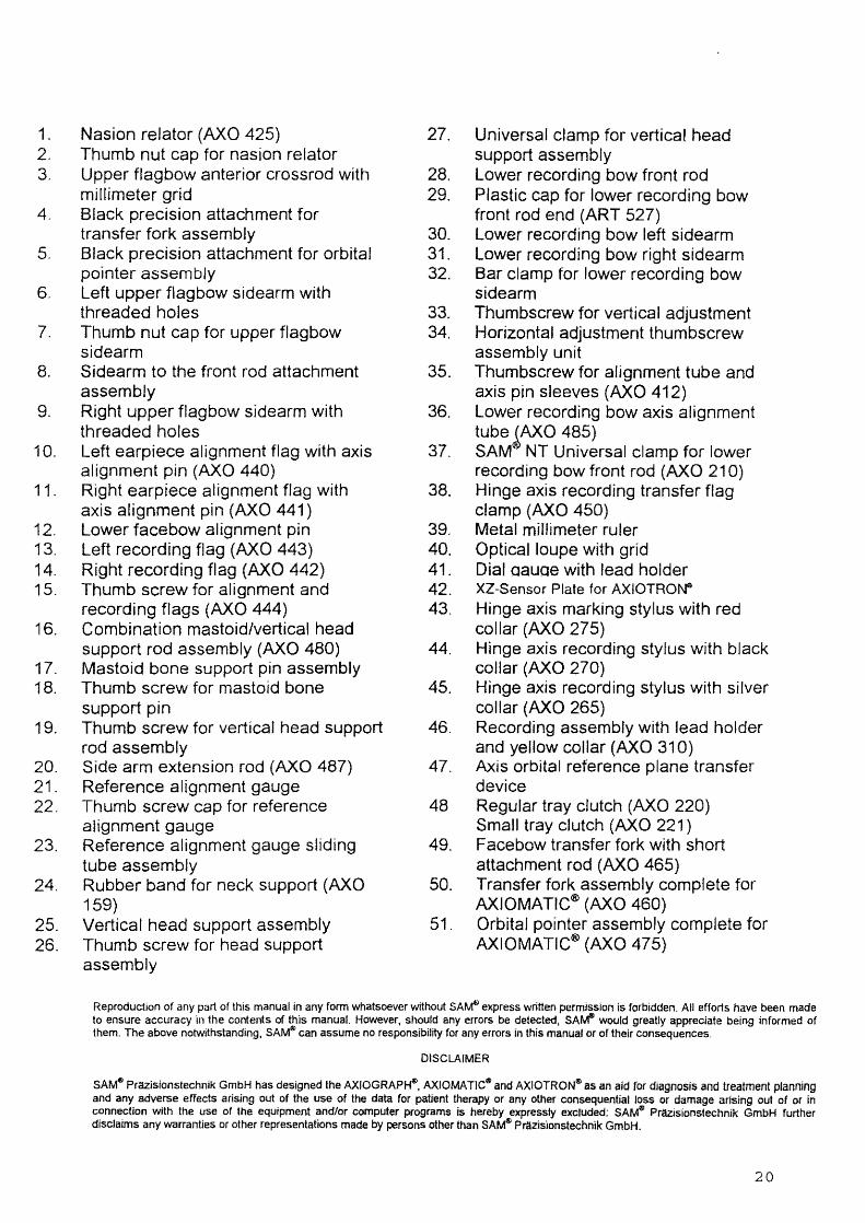
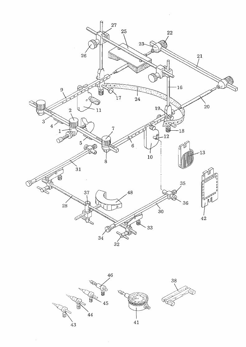
Nasion relator (AXO 425) 27. Universal clamp for vertical head Thumb nut cap for nasion relator support assembly Upper flagbow anterior crossrod with 28. Lower recording bow front rod millimeter grid 29. Plastic cap for lower recording bow Black precision attachment for front rod end (ART 527) transfer fork assembly 30. Lower recording bow left sidearm Black precision attachment for orbital 31. Lower recording bow right sidearm pointer assembly 32. Bar clamp for lower recording bow Left upper flagbow sidearm with sidearm threaded holes 33. Thumbscrew for vertical adjustment Thumb nut cap for upper flagbow 34. Horizontal adjustment thumbscrew sidearm assembly unit Sidearm to the front rod attachment 35. Thumbscrew for alignment tube and assembly axis pin sleeves (AXO 412) Right upper flagbow sidearm with 36. Lower recording bow axis alignment threaded holes tube ~AXO 485) Left earpiece alignment flag with axis 37. SAM NT Universal clamp for lower alignment pin (AXO 440) recording bow front rod (AXO 210) Right earpiece alignment flag with 38. Hinge axis recording transfer flag axis alignment pin (AXO 441) clamp (AXO 450) Lower facebow alignment pin 39. Metal millimeter ruler Left recording flag (AXO 443) 40. Opticalloupe with grid Right recording flag (AXO 442) 41. Dial aauae with lead holder Thumb screw for alignment and 42. XZ-Sensor Plate for AXIOTRO~
recording flags (AXO 444) 43. Hinge axis marking stylus with red Combination mastoid/vertical head collar (AXO 275) support rod assembly (AXO 480) 44. Hinge axis recording stylus with black Mastoid bone support pin assembly collar (AXO 270) Thumb screw for mastoid bone 45. Hinge axis recording stylus with silver support pin collar (AXO 265) Thumb screw for vertical head support 46. Recording assembly with lead holder rod assembly and yellow collar (AXO 310) Side arm extension rod (AXO 487) 47. Axis orbital reference plane transfer Reference alignment gauge device Thumb screw cap for reference 48 Regular tray clutch (AXO 220) alignment gauge Small tray clutch (AXO 221 ) Reference alignment gauge sliding 49. Facebow transfer fork with short tube assembly attachment rod (AXO 465) Rubber band for neck support (AXO 50. Transfer fork assembly complete for 159) AXIOMATIC® (AXO 460) Vertical head support assembly 51. Orbital pointer assembly complete for Thumb screw for head support AXIOMATIC® (AXO 475) assembly
Reproduction of any part of this manual in any form whatsoever without SA~ express written permission is forbidden. AU efforts have been made to ensure accuracy in the contents of this manual. However, should any errors be detected, SA~ would greatly appreciate being informed of them. The above notwithstanding. SAM® can assume no responsibility for any errors in this manual or or their consequences.
DISCLAIMER
SAM4!) Prazisionstechnik GmbH has designed the AXIOGRAPH®. AXIOMATIC® and AXIOTRON® as an aid for diagnosis and treatment planning and any adverse effects arising out of the use of the data for patient therapy or any other consequential loss or damage arising out of or in connection with the use of the equipment and/or computer programs is hereby expressly excluded: SAM" PrtiZisionstechnjk GmbH further disclaims any warranties or other representations made by persons other than SAM* Prazisionstechnik GmbH.
20

AXO 400 AXIOMA TIC®
Combination Flag/Facebow System Complete Conversion Kit for AXIOGRAPH® AXO 100 and AXO 200 (SAM® NT Universal Clamp and 2 bar clamp screws)
Conversion and u~grade kit for original AXIOGRAPH® and AXIOGRAPH II
7
3
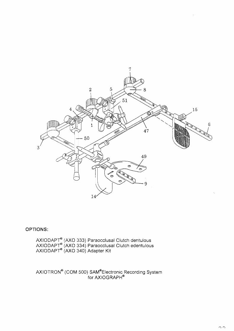
OPTIONS:
AXIODAP~ (AXO 333) Paraocclusal Clutch dentulous AXIODAP~ (AXO 334) Paraocclusal Clutch edentulous AXIODAP~ (AXO 340) Adapter Kit
AXtOTRON® (COM 500) SAM®Electronic Recording System for AXIOGRAPH®
32
41
SAM Pnlzisionstechnik GmbH Fussbergstrasse 1
D-82131 Gauting
Dear Customer,
we are in constant search for better technology. For improving the manuals we request your critical considerations and your input. Therefore we kindly ask you for your mailing adress
Product AXO ... SeriaLNo ............ .
Manual Version ...................................... .
Name .................................................................................................... .
Adress .« •••••••.•••••••••••••••••••••••••••••••••.••••••••••••••••••••••••••••••••••••••••• , ••••••••••• , ••
Fax ....................................................................................................... .
Delivered by ««««««««.«« •• « ••• « •••••••••••••••••••••••••••••••••••••• '« •••••••••••••••••• « •••••••••• « •• «
Please use next page for your comments, thank you for assistance.