axial piston variable pump a1vo series 10...bosch rexroth ag, re 92650/08.2015 4 a1vo series 10 |...
TRANSCRIPT

RE 92650 Edition: 08.2015, Bosch Rexroth AG
Characteristics ▶ Variable pump with axial piston rotary group of swash-
plate design for hydrostatic drives in open circuit ▶ Flow is proportional to the drive speed and displacement. ▶ The flow can be infinitely varied by controlling
the swashplate angle. ▶ Significant fuel savings of up to 15% compared to
fixed systems ▶ Optimized efficiency, though same power
at less fuel consumption ▶ Increased service life compared to gear pumps ▶ Compact design by integrated controller ▶ A wide range of highly adaptable control devices for all
important applications ▶ Stepless flow variation by adjusting the swashplate angle ▶ Low noise ▶ High power density ▶ Excellent suction characteristics ▶ High flexibility due to interchangeable through drive adapter
▶ For load-sensing-systems in smaller working machines ▶ Sizes 18, 28, 35 ▶ Nominal pressure 250 bar ▶ Maximum pressure 280 bar ▶ Open circuit
Axial piston variable pumpA1VO Series 10
RE 92650Edition: 08.2015Replaces: 02.2013
ContentsOrdering code 2Hydraulic fluids 4Shaft seal 5Working pressure range 6Technical data 7DR/DN pressure controller 9D3/D4 – Pressure controller with override 10DRS0/DNSO – Pressure controller with load sensing 11Dimensions size 18 and size 28 12Dimensions, size 35 14Through drives dimensions 16Overview of attachment options 17Combination pumps A1VO + A1VO 18Connector for solenoids 19Installation instructions 20Project planning notes 22Safety instructions 22

Bosch Rexroth AG, RE 92650/08.2015
2 A1VO Series 10 | Axial piston variable pumpOrdering code
Axial piston unit01 Variable swashplate design, nominal pressure 250 bar, maximum pressure 280 bar A1V
Operating mode02 Pump, open circuit O
Size (NG)03 Geometric displacement, see “Technical data” on page 7 018 028 035
Control device 018 028 03504 Pressure con-
trollerSetting range 100 to 250 bar
● ○ ● DR
with load sensing ● ○ ● DRS0
Setting range 20 to 100 bar ● ○ ● DN
with load sensing ● ○ ● DNS0
with override, electric-proportional, negative control2) U = 12 V ● ○ ● D3
U = 24 V ● ○ ● D4
Controller design and mounting05 Built-on2) ○ ○ ○ A
Cartridge ● ○ ● C
Setting06 Adjustable 2
Connector for solenoids1) (see page 19)
07 Without connector (without solenoid, only for hydraulic control) ● ○ ● 0
DEUTSCH - molded connector, 2-pin, without suppressor diode ● ○ ● P
Additional function08 Without additional function 0
Series09 Series 1, index 0 10
Design of ports and fastening threads10 ANSI, port threads with O-ring seal according to ISO 11926, metric fastening thread
on through drive version● ○ ● B
ISO, port threads with O-ring seal according to ISO 6149, metric fastening thread on through drive version
● ○ ● M
Direction of rotation11 Viewed on drive shaft clockwise R
counter-clockwise L
Sealing material12 FKM (fluoroelastomer) V
Mounting flanges13 SAE J744 82-2 ● ○ ○ A2
101-2 ○ ○ ● B2
ISO 3019-2 80-2 ○ ○ ○ K2
1) Connectors for other electric components may differ2) Currently, only D3 and D4 controllers available as mounted ver-
sions. All the other controllers are always cartridge solutions.
Ordering code
01 02 03 04 05 06 07 08 09 10 11 12 13 14 15 16 17 18
A1V O 2 0 / 10 V 00 – 0

RE 92650/08.2015, Bosch Rexroth AG
Axial piston variable pump | A1VO Series 10 Ordering code
3
3) For size 35, not for through drive4) According to ANSI B92.1a5) Mounting drillings pattern viewed on through drive, with service
line port B on right.
01 02 03 04 05 06 07 08 09 10 11 12 13 14 15 16 17 18
A1V O 2 0 / 10 V 00 – 0
Drive shaft (permissible input torque, see page 8) 018 028 03514 Splined shaft ANSI B92.1a 5/8 in 9T 16/32DP ○ ○ – S2
3/4 in 11T 16/32DP ○ ○ – S3
7/8 in 13T 16/32 DP3) ● ○ ● S4
1 in 15T 16/32DP – – ● S5
Service line port15 Threaded ports B and S on opposite sides ● ○ ● 1
Threaded ports B and S at rear; not for through drive ● ○ ○ 9
Through drives (for attachment options, see page 17)
16 Flange SAE J744 Hub for splined shaft4)
Diameter Attachment5) Designation Diameter Designation 018 028 035Without through drive 0000
82-2 (A) A2 5/8 in 9T 16/32 DP S2 ● ○ ● A2S2
3/4 in 11T 16/32 DP S3 ● ○ ● A2S3
7/8 in 13T 16/32 DP S4 ● ○ ● A2S4
101-2 (B) B2 7/8 in 13T 16/32 DP S4 ● ○ ● B2S4
1 in 15T 16/32 DP S5 – – ● B2S5
With mounted auxiliary pump Displacement– ○ ○ Hxx0
xx cm3 (e.g. H200 at 20 cm3)
Reduction of geometric displacement17 Without reduction 00
Standard / special version18 Standard version 0
● = Available ○ = On request – = Not available
NotesNote the project planning notes on page 22.
Bosch Rexroth AG, RE 92650/08.2015
4 A1VO Series 10 | Axial piston variable pumpHydraulic fluids
Hydraulic fluids
The A1VO variable pump is designed for operation with HLP mineral oil according to DIN 51524. Application instructions and requirements for hydraulic fluids should be taken from the following data sheets before the start of project planning:
▶ 90220: Hydraulic fluids based on mineral oils and related hydrocarbons
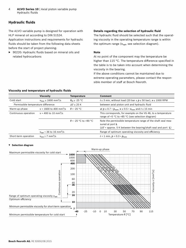
Details regarding the selection of hydraulic fluidThe hydraulic fluid should be selected such that the operat-ing viscosity in the operating temperature range is within the optimum range (νopt, see selection diagram).
NoteAt no point of the component may the temperature be higher than 115 °C. The temperature difference specified in the table is to be taken into account when determining the viscosity in the bearing.If the above conditions cannot be maintained due to extreme operating parameters, please contact the respon-sible member of staff at Bosch Rexroth.
Viscosity and temperature of hydraulic fluids
Viscosity Temperature Comment
Cold start νmax ≤ 1600 mm2/s θSt ≥ -25 °C t ≤ 3 min, without load (20 bar ≤ p ≤ 50 bar), n ≤ 1000 RPM
Permissible temperature difference ΔT ≤ 25 K between axial piston unit and hydraulic fluid
Warm-up phase ν < 1600 to 400 mm2/s θ = -25 °C at p ≤ 0.7 • pnom, n ≤ 0.5 • nnom and t ≤ 15 min
Continuous operation ν = 400 to 10 mm2/s This corresponds, for example on the VG 46, to a temperature range of +5 °C to +85 °C (see selection diagram)
θ = -25 °C to +90 °C Note the permissible temperature range of the shaft seal mea-sured at port L(ΔT = approx. 5 K between the bearing/shaft seal and port L)
νopt = 36 to 16 mm2/s Range of optimum operating viscosity and efficiency
Short-term operation νmin ≥ 7 mm2/s t < 1 min, p < 0.3 • pnom
▼ Selection diagram
-40 -25 -10 10 30 50 90 1157007
10
4060
20
100
200
400600
10001600
VG 22VG 32VG 46VG 68VG 100
16
36
Range of optimum operating viscosity vopt
Optimum efficiency
Maximum permissible viscosity for cold start
Minimum permissible viscosity for short-term operation
Temperature θ [°C]
Visc
osity
v [
mm
2 /s]
Con
tinuo
us o
pera
tion
Warm-up phase
Minimum permissible temperature for cold start

RE 92650/08.2015, Bosch Rexroth AG
Axial piston variable pump | A1VO Series 10 Shaft seal
5
Filtration of the hydraulic fluidFiner filtration improves the cleanliness level of the hydraulic fluid, which increases the service life of the axial piston unit. In order to guarantee the functional reliability of the axial piston unit it is necessary to carry out a gravimetric evalua-tion of the hydraulic fluid to determine the particle contam-ination and the cleanliness level according to ISO 4406. A cleanliness level of at least 20/18/15 must be maintained.At very high hydraulic fluid temperatures (90 °C to maximum 115 °C), at least cleanliness level 19/17/14 according to ISO 4406 is necessary.Please contact us if the above classes cannot be observed.
Shaft seal
The FKM shaft seal ring may be used for leakage tempera-tures from -25 °C to +115 °C.
NoteFor the temperature range below -25 °C, the values in the table on page 4 are to be observed.

Bosch Rexroth AG, RE 92650/08.2015
6 A1VO Series 10 | Axial piston variable pumpWorking pressure range
Working pressure range
Pressure at service line port B Definition
Nominal pressure pnom 250 bar absolute The nominal pressure corresponds to the maximum design pressure.
Maximum pressure pmax 280 bar absolute The maximum pressure corresponds the maximum working pressure within the single operating period. The sum of the single operating periods must not exceed the total operating period (maximum number of cycles: approx. 1 million).
Single operating period 0.05 s
Total operating period 14 h
Minimum pressure pB abs (high-pressure side)
14 bar1) absolute Minimum pressure on the high-pressure side (B) which is required in order to pre-vent damage to the axial piston unit.
Rate of pressure change RA max 16000 bar/s Maximum permissible rate of pressure build-up and reduction during a pressure change over the entire pressure range.
Pressure at suction port S (inlet)
Minimum pressure pS min 0.8 bar absolute Minimum pressure at suction port S (inlet) that is required in order to avoid dam-age to the axial piston unit. The minimum pressure depends on the speed and dis-placement of the axial piston unit.
Maximum pressure pS max 5 bar absolute
Leakage pressure at port L1, L2
Maximum pressure pL max 2 bar absolute Maximum 0.5 bar higher than inlet pressure at port S, but not higher than pL max.
▼ Rate of pressure change RA max
pnom
∆t
∆p
Time t
Pres
sure
p
▼ Pressure definition
Pres
sure
p
t1
t2tnSingle operating period
Minimum pressure (high-pressure side)
Maximum pressure pmax
Nominal pressure pnom
Time t
Total operating period = t1 + t2 + ... + tn
NoteWorking pressure range valid when using hydraulic fluids based on mineral oils. Values for other hydraulic fluids, please contact us.
1) Please contact us about lower pressures

RE 92650/08.2015, Bosch Rexroth AG
Axial piston variable pump | A1VO Series 10 Technical data
7
Technical data
Size NG 018 035
Displacement, geometric, per revolution Vg max
Vg min
cm3
cm3180
350
Maximum rotational speed1)2)
at Vg max
at Vg ≤ Vg max
nnom
nmax
rpmrpm
33003300
30003000
Flow at nnom and Vg max qv l/min 59 105
Power at nnom, Vg max and Δp = 250 bar P kW 25 44
Torque at Vg max and Δp = 250 bar T Nm 72 139
Rotary stiffness of drive shaft
5/8 in 9T 16/32DP S2 c kNm/rad 6.2 –
3/4 in 11T 16/32DP S3 c kNm/rad 9.9 –
7/8 in 13T 16/32 DP S4 c kNm/rad – 18.6
1 in 15T 16/32DP S5 c kNm/rad – 22.9
Moment of inertia for rotary group JTW kgm2 0.000505 0.00159
Maximum angular acceleration5) α rad/s² 6800 5000
Case volume V l 0.5 0.6
Weight (without through drive) approx. m kg 11.5 18.4
Weight (with through drive) approx. m kg 12.2 19.8
Determining operating characteristics
Flow qv =Vg × n × ηv [l/min]
1000
Torque T =Vg × Δp
[Nm]20 × π × ηhm
Power P =2 π × T × n
=qv × Δp
[kW]60000 600 × ηt
Key
Vg Displacement per revolution [cm3]Δp Differential pressure [bar]n Rotational speed [rpm]ηv Volumetric efficiencyηhm Hydraulic mechanical efficiencyηt Total efficiency (ηt = ηv • ηhm)
Note ▶ Theoretical values, without efficiency and tolerances;
values rounded. ▶ Exceeding the maximum or falling below the minimum
permissible values can lead to a loss of function, a reduc-tion in operational service life or total destruction of the axial piston unit. Bosch Rexroth recommend testing the loads by means of experiment or calculation / simulation and comparison with the permissible values.
1) The values are valid: ‒ For the optimum viscosity range from νopt = 36 to 16 mm2/s ‒ For hydraulic fluid based on mineral oils – For a pressure psuction ≥ 1 bar absolute at suction port S.
2) For a pressure psuction < 1 bar at suction port S, please contact us.
3) The data are valid at values between the minimum required and maximum permissible speed. Valid for external excitation (e.g., diesel engine 2 to 8 times rotary frequency; cardan shaft twice the rotary frequency). The limit value is only valid for a single pump. The load capacity of the connection parts must be considered.

Bosch Rexroth AG, RE 92650/08.2015
8 A1VO Series 10 | Axial piston variable pumpWorking pressure range
Permissible input and through-drive torques
Size 018 035
Torque at Vg max and Δp = 250 bar1) Tmax Nm 72 139
Input torque at drive shaft, maximum2)
S2 5/8 in TE max Nm 59 –
S3 3/4 in TE max Nm 143 –
S4 7/8 in TE max Nm – –
S5 1 in TE max Nm – 319
Through-drive torque, maximum1) TD max Nm 72 139
▼ Torque distribution
TE
TD
T1 T2
T31st Pump 2nd Pump
Torque at 1st Pump T1
Torque at 2nd Pump T2
Torque at 3rd Pump T3
Input torque TE = T1 + T2 + T3
TE < TE max
Through-drive torque TD = T2 + T3 TD < TD max
NoteFor axial and/or radial loading (pinion, v-belt), please contact us!
1) Efficiency not considered2) For drive shafts free of radial force

RE 92650/08.2015, Bosch Rexroth AG
Axial piston variable pump | A1VO Series 10 DR/DN pressure controller
9
DR/DN pressure controller
The pressure controller limits the maximum pressure at the pump outlet within the control range of the variable pump. The variable pump only supplies as much hydraulic fluid as is required by the consumers. If the operating pressure exceeds the pressure setting at the pressure valve, the pump will regu-late to a smaller displacement to reduce the control differential.
▶ Basic position in depressurized state:Vg max. ▶ DR
Setting range 1) for pressure control 100 to 250 bar. Standard 250 bar DN Setting range1) for pressure control 20 to 100 bar. Standard is 100 bar
▼ Characteristic curve DR
250
qv min qv max
100
Wor
king
pre
ssur
e p
[bar
]
Flow qV [L/min]
Hys
tere
sis/
pres
sure
ris
e Δp
max
▼ Schematic DR
L2L1
B
S
X
Controller data
NG 18 35
Hysteresis and repeat precision Δp Maximum 5 bar
Pilot fluid consumption Approx. 3 l/min max.
1) In order to prevent damage to the pump and the system, the permissible setting range must not be exceeded. Lower values on request

Bosch Rexroth AG, RE 92650/08.2015
10 A1VO Series 10 | Axial piston variable pumpD3/D4 – Pressure controller with override
D3/D4 – Pressure controller with override
With electric pressure adjustment using a proportional solenoid, the high pressure can be freely adjusted depend-ing on the solenoid current. When the load pressure is changed at the consumer, the pump flow volume is adjusted so that the specified pressure is achieved again. If the solenoid current drops below the beginning of con-trol, the unit will go to the set maximum pressure. The same thing applies if the pilot signal is lost.
▼ Current-pressure characteristic curve (negative characteristic curve)
250
0 1
140
D3/D4
Wor
king
pre
ssur
e p
[bar
]
Deactivation of control
Maximum adjustable controller pressure
Minimum adjustable controller pressure
Current I/I max
Characteristic curve measured with pump in zero stroke.Further information on request.

RE 92650/08.2015, Bosch Rexroth AG
Axial piston variable pump | A1VO Series 10 DRS0/DNSO – Pressure controller with load sensing
11
DRS0/DNSO – Pressure controller with load sensing
In addition to the pressure controller function (DR), the load-sensing controller works as a flow controller that operates as a function of the load pressure to regulate the pump displace-ment to match the consumer flow requirement. The load sens-ing controller compares pressure before and after the metering orifice and keeps the pressure drop (differential pressure Δp) across the orifice – and therefore the flow – constant.The swiveling in due to the pressure or flow controller will always take priority.
▶ DRS0 Setting range 1) for pressure control 100 to 250 bar.
▶ DNS0 Setting range 1) for pressure control 20 to 100 bar.
NoteThe DRS0/DNSO version has no connection from X to the reservoir, which means that the LS relief has to be incorpo-rated into the system.
▼ Characteristic curve DRS0
250
100
qv min qv max
Wor
king
pre
ssur
e p
[bar
]
Flow qv [ltr./min]
Hys
tere
sis/
pres
sure
ris
e Δp
max
▼ Characteristic curve at variable speed
qV max
qV min
n min n max
Flow
qv [
ltr./
min
]
Speed n [rpm]
Hys
tere
sis
ΔqV m
ax
▼ Schematic DRS0
DR
S0
L2L1
B 1
S
X
1 The metering orifice (control block) is not included in the scope of delivery.
Differential pressure ∆pStandard setting: 14 bar. If another setting is required, please state in clear text.
Control dataFor data for the pressure controller DR, please refer to page 9. Maximum flow differential (hysteresis and increase) measured at drive speed n = 1500 rpm and tfluid = 50 °C
NG 18 35
Volume flow difference ΔqV max 3 l/min
Maximum control fluid consumptionapprox. 4 l/min
1) In order to prevent damage to the pump and the system, the permissible setting range must not be exceeded. Lower values on request

Bosch Rexroth AG, RE 92650/08.2015
12 A1VO Series 10 | Axial piston variable pumpDimensions size 18 and size 28
Dimensions [mm]
Dimensions size 18 and size 28
DR, DN – Pressure controller / DRS0, DNS0 – Pressure control with load sensing, clockwise rotation
SL2
B
S B
X
X
L1
L1
L2
max. 9.7max. 6.4
ø82.
55
70.5
YX
-0.0
54
54.5
(L2)
55(S)
54(B; L1; X)
142.7
142.7
131.8161.6
11.2
7.31)
70.52.31)
77.5
58.5
179.7 (176.92))(181.13) L2)
106.4133
17.5
3134
138.2971)
26.5 34
33.6
8.5
2.52935
12.7
3041
.5
Flange A2ISO 3019-1
View YView XPort plate 1
1) Center of gravity2) Connection surfaces S, B, X, L1 and L2 with plate 93) With plates 9 and L2 closed only
View XPort plate 9

RE 92650/08.2015, Bosch Rexroth AG
Axial piston variable pump | A1VO Series 10 Dimensions size 18 and size 28
13Dimensions [mm]
▼ Splined shaft SAE J744
S4 – 7/8 in 13T 16/32DP1)
41
33
18
Ø 4
5.2 Ø 2
1.5
Center boreR 4 × 8.5 DIN 332
Ports and fastening threads version “B”
Ports Standard4) Size3) pmax abs [bar]5) State8)
B Service line port ISO 11926 1 1/16-12UN-2B; 20 deep 280 O
S Suction port ISO 11926 1 5/16-12UN-2B; 20 deep 5 O
L1 Case drain port ISO 11926 9/16-18UNF-2B; 13 deep 10 O6)
L2 Case drain port ISO 11926 9/16-18-18UNF-2B; 13 deep 10 X6 )
X Pilot signal ISO 11926 7/16-20UNF-2B; 12 deep 280 O7)
Ports and fastening threads version “M”
Ports Standard4) Size3) pmax abs [bar]5) State8)
B Service line port ISO 6149 M33 × 2; 20 deep 280 O
S Suction port ISO 6149 M42 × 2; 20 deep 5 O
L1 Case drain port ISO 6149 M18 × 1.5; 13 deep 10 O6)
L2 Case drain port ISO 6149 M18 × 1.5; 13 deep 10 X6 )
X Pilot signal ISO 6149 M12 × 1.5; 12 deep 280 O7)
1) Involute spline according to ANSI B92.1a, 30° pressure angle, flat root, side fit, tolerance class 5
2) Thread according to ASME B1.13) Observe the “Project planning notes” on page 22 concerning
the maximum tightening torques.4) The spot face can be deeper than specified in the standard.
5) Depending on the application, momentary pressure peaks can occur. Keep this in mind when selecting measuring devices and fittings.
6) Depending on the installation position, L1 or L2 must be connected (see also the installation instructions on page 20).
7) Only if an S0 controller is present.8) O = Must be connected (plugged on delivery)
X = Plugged (in normal operation)

Bosch Rexroth AG, RE 92650/08.2015
14 A1VO Series 10 | Axial piston variable pumpDimensions, size 35
Dimensions [mm]
Dimensions, size 35
DR, DN – Pressure controller / DRS0, DNS0 – Pressure control with load sensing, clockwise rotation
S
B
X
L2 L1
1631031)
149
149182.5
163
203
8673
69.5
57(X
, L1,
B)
57
max. 9.7max. 6.4
174
146
61
ø101
.64.
91)1.
31)
74.5ø 14.3
Y
X
61
-0.0
5
Flange B2ISO 3019-1
View YView X
1) Center of gravity

RE 92650/08.2015, Bosch Rexroth AG
Axial piston variable pump | A1VO Series 10 Dimensions, size 35
15Dimensions [mm]
▼ Splined shaft SAE J744
S4 – 7/8 in 13T 16/32DP1) S5 – 1 in 15T 16/32DP1)
41
165
33
18
1/4-
20U
NC
-2B
2)3)
Ø 5
6.9 Ø 2
546
Ø 2
5
165
38
23
1/4-
20U
NC
-2B
2)3)
Ø 5
6.9
Ports and fastening threads version “B”
Ports Standard4) Size3) pmax abs [bar]5) State8)
B Service line port ISO 11926 1 5/16-12UN-2B; 20 deep 280 O
S Suction port ISO 11926 1 5/8-12UN-2B; 20 deep 5 O
L1 Case drain port ISO 11926 3/4-16UNF-2B; 15 deep 10 O6)
L2 Case drain port ISO 11926 3/4-16UNF-2B; 15 deep 10 X6)
X Pilot signal ISO 11926 7/16-20UNF-2B; 12 deep 280 O7)
Ports and fastening threads version “M”
Ports Standard4) Size3) pmax abs [bar]5) State8)
B Service line port ISO 6149 M33 × 2; 20 deep 280 O
S Suction port ISO 6149 M42 × 2; 20 deep 5 O
L1 Case drain port ISO 6149 M18 × 1.5; 13 deep 10 O6)
L2 Case drain port ISO 6149 M18 × 1.5; 13 deep 10 X6 )
X Pilot signal ISO 6149 M12 × 1.5; 12 deep 280 O7)
NoteWith all the ports – in particular when connecting port S – use the stud ends provided for the standard with the corresponding width across flats. Please contact us about larger widths across flats.
1) Involute spline according to ANSI B92.1a, 30° pressure angle, flat root, side fit, tolerance class 5
2) Thread according to ASME B1.13) Observe the “Project planning notes” on page 22 concerning
the maximum tightening torques.4) The spot face can be deeper than specified in the standard.5) Depending on the application, momentary pressure peaks can occur.
Keep this in mind when selecting measuring devices and fittings.
6) Depending on the installation position, L1 or L2 must be connected (see also the installation instructions on page 20).
7) Only if an S0 controller is present.8) O = Must be connected (plugged on delivery)
X = Plugged (in normal operation)

Bosch Rexroth AG, RE 92650/08.2015
16 A1VO Series 10 | Axial piston variable pumpThrough drives dimensions
Dimensions [mm]
Through drives dimensions
Flange SAE J744 Hub for splined shaft1) Availability NG Code
Diameter Attachment2) Designation Diameter Designation 018 028 035
82-2 (A) A2 5/8 in 9T 16/32 DP S2 ● ○ ● A2S2
3/4 in 11T 16/32 DP S3 ● ○ ● A2S3
7/8 in 13T 16/32 DP S4 ● ○ ● A2S4
101-2 (B) B2 7/8 in 13T 16/32 DP S4 ● ○ ● B2S4
1 in 15T 16/32 DP S5 – – ● B2S5
● = Available ○ = On request – = Not available
1) According to ANSI B92.1a, 30° pressure angle, flat root, side fit, tolerance class 5
2) Mounting drillings pattern viewed on through drive, with service line port B on right.
3) Continuous thread according to DIN 13; observe the “Project planning notes” on page 22 concerning the maximum tightening torques.
▼ 82-2 (A)
M2
106.4M10 x 1.5
8
Ø82
.55
+0.0
2+0
.05
M1 (to mounting flange)
Short code
NG M1 M2
A2S2 018 203.2 32
028 203.2 32
035 227.6 32
A2S3 018 203.2 38
028 203.2 38
035 227.6 38
A2S4 018 203.2 41
028 203.2 41
035 227.6 41
▼ 101-2 (B)
M2
146M12 x 1.75
11
Ø10
1.6
+0.0
2+0
.05
M1 (to mounting flange)
Short code
NG M1 M2
B2S4 018 203.2 41
028 203.2 41
035 227.6 41
B2S5 035 227.6 46

RE 92650/08.2015, Bosch Rexroth AG
Axial piston variable pump | A1VO Series 10 Overview of attachment options
17Dimensions [mm]
Overview of attachment options
Through drive1) Fitting options – 2nd pump
Flange Hub for splined shaft
Short code
A1VO/10 NG (shaft)
A4VG/32 NG (shaft)
A10VG/10 NG (shaft)
A10VO/52/53 NG (shaft)
A10VNO/52/53 NG (shaft)
A10V(S)O/31 NG (shaft)
External gear pump2)
82-2 (A) 5/8 in A2S2 18, 28 (S2) – – 10 (U), 18 (U) – 18 (U) Series F
3/4 in A2S3 18, 28 (S3) – – 10 (S), 18 (S, R)
28 (R) 18 (S, R) –
101-2 (B) 7/8 in B2S4 35 (S4) – 18 (S) 28 (S, R) – 28 (S, R) Series N Series G
1 in B2S5 35 (S5) 28 (S) 28 (S) – – – –
1) Additional through drives are available on request2) Bosch Rexroth recommends special versions of the external gear
pumps. Please contact us.

Bosch Rexroth AG, RE 92650/08.2015
18 A1VO Series 10 | Axial piston variable pumpCombination pumps A1VO + A1VO
18
Combination pumps A1VO + A1VO
Total length AA1VO (1st pump) A1VO (2nd pump)
NG18 NG35
NG18 375 –
NG35 403.3 431
By using combination pumps, it is possible to have inde-pendent circuits without the need for splitter gearboxes. When ordering combination pumps, the type designations of the 1st and 2nd pump must be linked by a “+”.Order example:A1VO035DRS0C100/10BRVB2S51B2S500+ A1VO035DRS0C100/10BRVB2S51000000It is permissible to use a combination of two single pumps of the same size (tandem pump), considering a dynamic mass acceleration of maximum 10 g (= 98.1 m/s2) without additional support brackets. For combination pumps consisting of more than two pumps, the mounting flange must be rated for the permis-sible mass torque.
Permissible mass moment of inertia
Size 18 35
static Tm Nm 500 890
dynamic at 10 g (98.1 m/s2) Tm Nm 50 89
Weight without through-drive plate (e.g. 2nd pump)Weight with through-drive plate
m kg 11.512.2
18.419.8
Distance, center of gravity without through drive l1 mm 93 100
Distance, center of gravity with through drive l1 mm 99 108
A
l1
m1 m2
l2
m1, m2 Weight of pump [kg]
l1, l2, Distance, center of gravity
[mm]
Tm = (m1 × l1 + m2 × l2 ) ×1
[Nm]102
1st pump 2nd pump

RE 92650/08.2015, Bosch Rexroth AG
Axial piston variable pump | A1VO Series 10 Connector for solenoids
19Dimensions [mm]
Connector for solenoids
DEUTSCH DT04-2P-EP04Molded connector, 2-pin, without bidirectional suppressor diode There is the following type of protection with mounted mating connector:
▶ IP67 (DIN/EN 60529) and ▶ IP69K (DIN 40050-9)
▼ Circuit symbol
▼ Mating connector DEUTSCH DT06-2S-EP04
Consisting of DT designation
1 housing DT06-2S-EP04
1 wedge W2S
2 sockets 0462-201-16141
The mating connector is not included in the scope of delivery. This can be supplied by Bosch Rexroth on request (material number R902601804).
ø37
68.550
36.7
(2)(1)
36.7
Changing connector orientationIf necessary, you can change the connector orientation by turning the solenoid housing.To do this, proceed as follows:
▶ Loosen the mounting nut (1) of the solenoid. To do this, turn the mounting nut (1) one turn counter-clockwise.
▶ Turn the solenoid body (2) to the desired orientation. ▶ Retighten the mounting nut.
Tightening torque: 5+1 Nm. (WAF 26, 12-sided DIN 3124)
On delivery, the position of the connector may differ from that shown in the brochure or drawing.

Bosch Rexroth AG, RE 92650/08.2015
20 A1VO Series 10 | Axial piston variable pumpInstallation instructions
1) Because complete air bleeding and filling are not possible in this position, the pump should be air bled and filled in a horizontal po-sition before installation.
Installation instructions
GeneralDuring commissioning and operation, the axial piston unit must be filled with hydraulic fluid and air bled. This must also be observed following a relatively long standstill as the axial piston unit may drain back to the reservoir via the hydraulic lines.Particularly with the “drive shaft up/down” installation position, filling and air bleeding must be carried out com-pletely as there is, for example, a danger of dry running.The leakage in the pump housing must be discharged to the reservoir via the highest available drain port (L1, L2).For combinations of multiple units, the case drain fluid must be drained off at each pump.If a shared drain line is used for several units, make sure that the respective case pressure is not exceeded. The shared drain line must be dimensioned to ensure that the maximum permissible case pressure of all connected units is not exceeded in any operational circumstances, particu-larly at cold start. If this is not possible, separate drain lines must be laid if necessary.To achieve favorable noise values, decouple all connecting lines using elastic elements and avoid above-reservoir installation. In all operating conditions, the suction lines and the drain lines must flow into the reservoir below the minimum fluid level. The permissible suction height hS results from the overall loss of pressure. However, it must not be higher than hS max = 800 mm. The minimum suction pressure at port S must also not fall below 0.8 bar absolute during operation and during cold start.When designing the reservoir, ensure that there is sufficient distancebetween the suction line and the drain line. This minimizes oil turbulence and carries out degassing, which prevents the heated hydraulic fluid from being sucked directly back in again.
NoteIn certain installation positions, an influence on the con-trol characteristic curves can be expected. Gravity, dead weight and case pressure can cause minor shifts in char-acteristics and changes in response time.
Installation position See examples 1 to 11 below. Additional installation positions are available upon request.Recommended installation position: 1 and 2
Below-reservoir installation (standard)Below-reservoir installation means that the axial piston unit is installed outside of the reservoir below the minimum fluid level.
Installation positionAir bleeding
Filling
1
S
SB
ht min
hmin
L1
L1 S + L1
2
S L2
SB
ht min
hmin
L2 S + L2
3
SL1
SB
ht min
hmin
L1 or L2 S + L1 or L2
41)
S
L2
SB
ht min
hmin
L1 or L2 S + L1 or L2

RE 92650/08.2015, Bosch Rexroth AG
Axial piston variable pump | A1VO Series 10 Installation instructions
21
1) Because complete air bleeding and filling are not possible in this position, the pump should be air bled and filled in a horizontal position before installation.
Above-reservoir installationAbove-reservoir installation means that the axial piston unit is installed above the minimum fluid level of the reservoir. To prevent the axial piston unit from draining in position 8, the height difference hES min must be at least 25 mm.Observe the maximum permissible suction height hS max = 800 mm.
Installation position Air bleeding
Filling
5
SSB
ht min
hmin
L1
hS max
L1 L1
6
hS max
SL2
SB
ht min
hmin
L2 L2
7SL1
SB
ht min
hmin
hS max
L1 or S L1 or S
81)
hES min
hS maxSB
ht min
hmin
S
L1
L1 L1
Inside-reservoir installationInside-reservoir installation is when the axial piston unit is installed in the reservoir below the minimum fluid level. The axial piston unit is completely below the hydraulic fluid.If the minimum fluid level is equal to or below the upper edge of the pump, see chapter “Above-reservoir installation”.Axial piston units with electrical components (e.g., electric control, sensors) may not be installed in a reservoir below the fluid level.
Installation position Air bleeding Filling
9
SB
S hmin
ht min
L1
Via the high-est available port L1
Automatically via the open port L1 due to the position under the hydrau-lic fluid level
10
SB S
hmin
ht min
L2
Via the high-est available port L2
Automatically via the open port L2
due to the position below the hydrau-lic fluid level
111)
SB
S
ht min
hmin
L2
Key
L1, L2 Filling / air bleeding
S Suction port
SB Baffle (baffle plate)
ht min Minimum required immersion depth (200 mm)
hmin Minimum required spacing to reservoir bottom (100 mm)
hES min Minimum necessary height needed to protect the axial piston unit from draining (25 mm).
hS max Maximum permissible suction height (800 mm)

Bosch Rexroth AG, RE 92650/08.2015
22 A1VO Series 10 | Axial piston variable pumpProject planning notes
Project planning notes
▶ The A1VO variable pump is designed to be used in an open circuit.
▶ The project planning, installation and commissioning of the axial piston unit require the involvement of qualified skilled personnel.
▶ Before using the axial piston unit, please read the cor-responding instruction manual completely and thor-oughly. If necessary, request it from Bosch Rexroth.
▶ Before finalizing your design, request a binding installation drawing.
▶ The specified data and notes must be observed. ▶ Depending on the operating condition of the axial piston
unit (working pressure, fluid temperature), the charac-teristic curve may shift.
▶ Preservation: Our axial piston units are supplied as standard with preservative protection for a maximum of 12 months. If longer preservative protection is required (maximum 24 months), please specify this in plain text when placing your order. The preservation times apply under optimal storage conditions, details of these condi-tions can be found in the data sheet 90312 or the instruction manual.
▶ Not all variants of the product are approved for use in safety functions according to ISO 13849. Please consult the responsible contact person at Bosch Rexroth if you require reliability parameters (e.g. MTTFd) for functional safety.
▶ Depending on the type of control used, electromagnetic effects can be produced when using solenoids. When a direct current is applied, solenoids do not cause electro-magnetic interference nor is their operation impaired by electromagnetic interference. Other behavior can result when a modulated direct current (e.g. PWM signal) is applied. Potential electro-magnetic interference for persons (e.g. persons with a pacemaker) and other components must be tested by the machine manufacturer.
▶ Pressure controllers/pressure deposition are/is no safeguard from pressure overload. A pressure relief valve must be provided in the hydraulic system.
▶ Working ports: – The ports and fastening threads are designed for the
specified maximum pressure. The machine or system manufacturer must ensure that the connecting ele-ments and lines correspond to the specified operat-ing conditions (pressure, flow, hydraulic fluid, tem-perature) with the necessary safety factors.
– The working ports and function ports can only be used to accommodate hydraulic lines.
Safety instructions
▶ During and shortly after operation, there is a risk of burns on the axial piston unit and especially on the sole-noids. Take appropriate safety measures (e.g. by wearing protective clothing).
▶ Moving parts in control and regulation systems (e.g. valve spools) may in certain circumstances become stuck in an undefined position due to contamination (e.g. contami-nated hydraulic fluid, abrasion or residual dirt from components). As a result, the hydraulic fluid flow or build-up of torque of the axial piston unit will no longer respond correctly to the operator's commands. Even the use of different filter cartridges (external or internal inlet filter) will not rule out a fault but merely reduce the risk. The machine/system manufacturer must test whether remedial measures are needed on the machine for the application concerned in order to set the consumer being driven to a safe position (e.g. safe stop) and if necessary to ensure it is properly implemented.

RE 92650/08.2015, Bosch Rexroth AG
Axial piston variable pump | A1VO Series 10 Project planning notes
23

Bosch Rexroth AGMobile ApplicationsAn den Kelterwiesen 1472160 Horb a.N., GermanyTel. +49 7451 [email protected]
© This document, as well as the data, specifications and other information set forth in it, are the exclusive property of Bosch Rexroth AG. It may not be reproduced or given to third parties without its consent. The data specified above only serve to describe the product. No statements concerning a certain condition or suitability for a certain application can be derived from our information. The information given does not release the user from the obligation of own judgment and verification. It must be remembered that our products are subject to a natural process of wear and aging.
24 A1VO Series 10 | Axial piston variable pump