axial piston variable motor aa6vm series 63 · 4 a6vm series 63 | axial piston variable motor...
TRANSCRIPT

RE-A 91604/08.2016, Bosch Rexroth Corp.
Features Robust motor with long service life Approved for very high rotational speeds High control range (can be swiveled to zero) High torque Variety of controls Optionally with flushing and boost-pressure valve
mounted Bent-axis design
All-purpose high pressure motor Size 250 Nominal pressure 5100 psi (350 bar) Maximum pressure 5800 psi (400 bar) Open and closed circuits
Axial piston variable motorAA6VM series 63
RE-A 91604Edition: 08.2016Replaces: 03.2014
ContentsType code 2Hydraulic fluids 4Flow direction 5Bearing 5Shaft seal 5Operating pressure range 6Technical data 7HD – Proportional control, hydraulic 9EP – Proportional control, electric 13HZ – Two-point control, hydraulic 16EZ – Two-point control, electric 17HA – Automatic high-pressure related control 18DA – Automatic control, speed related 21Dimension 22Connector for solenoids 26Flushing and boost pressure valve 27Swivel angle indicator 28Speed sensor 29Installation instructions 30Project planning notes 32Safety instructions 33
Americas

Bosch Rexroth Corp., RE-A 91604/08.2016
2 A6VM series 63 | Axial piston variable motorType code
Type code
01 02 03 04 05 06 07 08 09 10 11 12 13 14 15 16 17 18 19 20
AA6V M 250 / 63 W – V S D –
Hydraulic fluid01 Mineral oil and HFD. HFD only in combination with long-life bearings "L" (without code)
HFB, HFC hydraulic fluid only in conjunction with long-life bearings “L” E
Axial piston unit02 Bent-axis design, variable, nominal pressure 5100 psi (350 bar), maximum pressure 5800 psi (400 bar) AA6V
Drive shaft bearing03 Standard bearing (without code)
Long-life bearing L
Operating mode04 Motor (plug-in motor A6VE, see data sheet 91606) M
Size (NG)05 Geometric displacement, see technical data on page 7 in cm3/rev 250
in in3/rev 15.25
Control device06 Proportional control hydraulic ΔpSt = 145 psi (10 bar) HD1
ΔpSt = 365 psi (25 bar) HD2
ΔpSt = 510 psi (35 bar) HD3
Proportional control electrical1) U = 12 V DC EP1
U = 24 V DC EP2
Two-point control hydraulic HZ
Two-point control electrical1) U = 12 V DC EZ1
U = 24 V DC EZ2
Automatic control high-pressure related with minimum pressure increase Δp ≤ approx. 145 psi (10 bar) HA1
with pressure increase Δp = 1450 psi (100 bar) HA2
Automatic control speed related pSt / pHD = 3/100 hydraulic travel direction valve DA
Pressure control/override (only for HD, EP)07 Without pressure control/override
Pressure control fixed setting fixed setting D
hydraulic override, two-point E2)
hydraulic remote control, proportional G
Overrides for the HA1 and HA2 controls08 Without override
Hydraulic override, remonte control, proportinal T
Series09 Series 6, index 3 63
Direction of rotation10 Viewed on drive shaft, bidirectional W
Setting range for displacement3)
11 Vg min = 0 to 0.4 Vg max Vg max = Vg max to 0.8 Vg max 1
Vg max > 0.4 Vg max to 0.8 Vg max Vg max = Vg max to 0.8 Vg max 2
= Available = On request ‒ = Not available1) Hirschmann connector Standard2) Fitted as standard with version D3) Please specify exact settings for Vg min and Vg max in plain text when
ordering: Vg min = ... in3 (cm3), Vg max = ... in3 (cm3)

RE-A 91604/08.2016, Bosch Rexroth Corp.
Axial piston variable motor | A6VM series 63 Type code
3
01 02 03 04 05 06 07 08 09 10 11 12 13 14 15 16 17 18 19 20
AA6V M 250 / 63 W – V S D –
4) Fastening threads, SAE5) Specify type code separately for sensor in accordance with data
sheet 95135 – HDD and observe the requirements for the electron-ics.
Sealing material12 FKM (fluoroelastomer) V
Drive shaft13 Splined shaft ANSI B92.1a S
Mounting flange14 SAE J744 ‒ 4-bolt 165-4 D
Working port4)
15 SAE working ports A and B at rear 51 0 510
7 517
SAE working ports A and B at side, opposite 52 0 520
7 527
Valves (see page 27)
Without valve 0
Flushing and boost-pressure valve, mounted 7
Speed sensor (see page 29)
16 Without speed sensor (without code)
Prepared for HDD speed sensor F
HDD speed sensor mounted5) H
Swivel angle sensor (see page 28)
17 Without swivel angle sensor (without code)
Optical swivel angle sensor V
Electric swivel angle sensor E
Beginning of control18 At Vg min (standard for HA) A
At Vg max (standard for HD, HZ, EP, EZ, DA) B
Standard / special version19 Standard version 0
Special version -S
= Available = On request = Not for new projects ‒ = Not available
Notices Note the project planning notes on page 32. When ordering, please provide the relevant technical
data additionally to the type code.

Bosch Rexroth Corp., RE-A 91604/08.2016
4 A6VM series 63 | Axial piston variable motorHydraulic fluids
Hydraulic fluids
The variable motor A6VM is designed for operation with mineral oil HLP according to DIN 51524. Application instructions and requirements for hydraulic fluids should be taken from the following data sheets before the start of project planning:
90220: Hydraulic fluids based on mineral oils and related hydrocarbons
90221: Environmentally acceptable hydraulic fluids 90222: Fire-resistant, water-free hydraulic fluids
(HFDR/HFDU) 90223: Fire-resistant, water-containing hydraulic fluids
(HFAE, HFAS, HFB, HFC) 90225: Axial piston units for operation with water-free
and water-containing fire-resistant hydraulic fluids (HFDR, HFDU, HFB, HFC).
Notes on selection of hydraulic fluidThe hydraulic fluid should be selected such that the operat-ing viscosity in the operating temperature range is within the optimum range (νopt see selection diagram).
Notice The variable motor A6VM is not suitable for operation with
HFA fluids. If operating with HFB-, HFC- and HFD or envi-ronmentally acceptable hydraulic fluids, the limitations regarding technical data or other seals must be observed.
At no point of the component may the temperature be higher than 239 °F (115 °C). The temperature differ-ence specified in the table is to be taken into account when determining the viscosity in the bearing.
If the above conditions cannot be maintained due to extreme operating parameters, we recommend the use of a flushing and boost-pressure valve (see page 27).
Viscosity and temperature of hydraulic fluids
Viscosity Shaft seal Temperature2) Comment
Cold start νmax ≤ 7400 SUS (1600 mm2/s)
FKM θSt ≥ −40 °F (−40 °C)θSt ≥ −13 °F (−25 °C)
t ≤ 3 min, without load p ≤ 725 psi (p ≤ 50 bar), n ≤ 1000 rpm, permissible temperature difference between axial piston unit and hydraulic fluid in the system max. 45 °F (25 K)
Warm-up phase ν < 7400 ... 1850 SUS (1600 ... 400 mm2/s)
t ≤ 15 min, p ≤ 0,7 × pnom and n ≤ 0,5 × nnom
Continuous operation
ν = 1850 ... 47 SUS (400 ... 10 mm2/s)1)
FKM θ ≤ +185 °F (+85 °C)θ ≤ +217 °F (+103 °C)
measured at port T
νopt = 16 ... 81 SUS (36 ... 16 mm2/s)
Range of optimum operating viscosity and efficiency
Short-term operation
νmin = 60 ... 49 SUS (10 ... 7 mm2/s)
FKM θ ≤ +185 °F (+85 °C) θ ≤ +217 °F (+103 °C)
t ≤ 3 min, p ≤ 0,3 × pnom, measured at port T
Selection diagram
−40(−40)
−13(−25)
14(−10)
50(10)
86(30)
104(40)
122(50)
195(90)
240(115)
158(70)
0(0)
49 (7)
60 (10)
190 (40)280 (60)
100 (20)
460 (100)
930 (200)
1850 (400)2800 (600)
4600 (1000)7400 (1600)
VG 22VG 32VG 46VG 68VG 100
82 (16)
170 (36)ν opt
Maximum permissible viscosity for cold start
Minimum permissible viscosity at short-term operation
Temperature θ [°F (°C)]
Visc
osity
ν [
SUS
(mm
2 /s)
]
Continuous operation
Warm-up phase
1) Corresponds e.g. with VG 46 a temperature range of +39 °F to +185 °F (+4 °C to +85 °C)(see selection diagram)
2) If the temperature to extreme operating parameters can not be met, please contact us.

RE-A 91604/08.2016, Bosch Rexroth Corp.
Axial piston variable motor | A6VM series 63 Flow direction
5
Filtration of the hydraulic fluidFiner filtration improves the cleanliness level of the hydraulic fluid, which increases the service life of the axial piston unit. A cleanliness level of at least 20/18/15 is to be maintained according to ISO 4406.At very high hydraulic fluid temperatures (195 °F (90 °C) to maximum 217 °F (103 °C), measured at port T), a cleanli-ness level of at least 19/17/14 according to ISO 4406 is necessary.
Influence of case pressure on beginning of controlAn increase in case pressure affects the beginning of con-trol when using the following control options:
HD, EP, HA, HA.T: Increase DA: Decrease
With the following settings, an increase in case pressure will have no effect on the beginning of control: HA.R and HA.U, EP, HAThe factory setting of the beginning of control is made at pabs = 15 psi (1 bar) case pressure.
Flow direction
Direction of rotation, viewed on drive shaft
clockwise counter-clockwise
A to B B to A
Bearing
Long-life bearingFor long service life and use with HF hydraulic fluids. Identi-cal external dimensions as motor with standard bearings. Subsequent conversion to long-life bearings is possible.
Flushing Flushing flow (recommended)
Size 250
qv flush [gmp (l/min)] 2.6 (10)
To reduce the leakage temperature, external case flushing is possible via port U or internally via a flushing valve.
Shaft seal
Permissible pressure loadingThe service life of the shaft seal is influenced by the rota-tional speed of the axial piston unit and the leakage pres-sure in the housing (case pressure). Momentary (t < 0.1 s) pressure peaks of up to 145 psi (10 bar) are allowed. Case pressures of a continuous 30 psi (2 bar) maximum are permitted to be able to utilize the entire speed range. Higher case pressures are permissible at lower rotational speeds (see diagram). The service life of the shaft seal decreases with increasing frequency of pressure peaks and increasing mean differen-tial pressure.The case pressure must be equal to or higher than the ambient pressure.
Diff
eren
tial p
ress
ure
Δp
[psi
(ba
r)]
Rotational speed n [rpm]2000 30000 1000 1500 2500500 3500 4000
0
15 (1)
30 (2)
45 (3)
60 (4)
75 (5)
The FKM shaft seal ring may be used for leakage tempera-tures from -13 °F to +240 °F (-25 °C to +115 °C). For appli-cation cases below -13 °F (-25 °C), an NBR shaft seal is required (permissible temperature range: -40 °F to +195 °F (-40 °C to +90 °C).

Bosch Rexroth Corp., RE-A 91604/08.2016
6 A6VM series 63 | Axial piston variable motorOperating pressure range
Operating pressure range
Pressure at working port A or B Definition
Nominal pressure pnom 5100 psi (350 bar) The nominal pressure corresponds to the maximum design pressure.
Maximum pressure pmax 5800 psi (400 bar) The maximum pressure corresponds to the maximum operating pres-sure within the single operating period. The sum of the single operating periods must not exceed the total operating period.
Single operating period 10 s
Total operating period 300 h
Minimum pressure (high-pressure side)
365 psi (25 bar) Minimum pressure at the high-pressure side (A or B) which is required in order to prevent damage to the axial piston unit.
Minimum pressure – pump operating mode (inlet)
See the diagram below To prevent damage to the axial piston motor in pump operating mode (change of high-pressure side with unchanged direction of rotation, e. g. when braking), a minimum pressure must be guaranteed at working port (inlet). This minimum pressure is dependent on the speed and displace-ment of the axial piston unit (see characteristic curve)
Summation pressure pSu
(pressure A + pressure B)10150 psi (700 bar) The summation pressure is the sum of the pressures at both working
ports (A and B)
Rate of pressure change RA max Maximum permissible rate of pressure build-up and reduction during a pressure change over the entire pressure range.With integrated pressure-relief valve 130530 psi/s (9000 bar/s)
Without pressure-relief valve 232060 psi/s (16000 bar/s)
Rate of pressure change RA max
pnom
∆t
∆p
Time t
Pres
sure
p
Pressure definition
Single operating period
Pres
sure
p
t1
t2tn
Minimum pressure (high-pressure side)
Maximum pressure pmax
Nominal pressure pnom
Time t
Total operating period = t1 + t2 + ... + tn
Minimum pressure – pump operating mode (inlet)
Vg max
Vg x
0.3 Vg max
15 (1)30 (2)
60 (4)
90 (6)
115 (8)
145 (10)
175 (12)
200 (14)
230 (16)
0 0.2 0.5 0.8 1.1 1.4
Inle
t pr
essu
re p
abs [
psi (
bar)
]
Rotational speed n / nnom
This diagram is valid only for the optimum viscosity range from νopt = 170 to 73 SUS (36 to 16 mm2/s). Please contact us if these conditions cannot be satisfied.
NoticeOperating pressure range valid when using hydraulic fluids based on mineral oils. Values for other hydraulic fluids, please contact us.

RE-A 91604/08.2016, Bosch Rexroth Corp.
Axial piston variable motor | A6VM series 63 Technical data
7
Technical data
Size NG 250
Displacement geometric, per revolution1)
Vg max in3 15.26
cm3 250Vg min in3 0
cm3 0Vg x in3 12.51
cm3 205Maximum rotational speed2) (while adher-ing to the maximum permissible inlet flow)
at Vg max nnom rpm 2700
at Vg < Vg x (see diagram)
nmax rpm 3300
at Vg 0 nmax rpm Please contact us
Inlet flow at nnom and Vg max qv max gpm 178
l/min 675Torque3) at Vg max and
Δp = 5800 psi (400 bar)
T lb-ft -
Nm -
at Vg max and Δp = 5100 psi (350 bar)
lb-ft 1026
Nm 1391
Rotary stiffness Vg max to Vg/2 cmin lb-ft/rad
kNm/rad 60Vg/2 to 0 (interpolated)
cmin lb-ft/rad
kNm/rad 181Moment of inertia for rotary group JTW lb-ft2 1.448
kgm2 0.061
Maximum angular acceleration α rad/s² 10000Case volume V gal 0.79
l 3.0Weight, approx. m lbs 220
kg 100
Speed rangeThe minimum rotational speed nmin is not restricted. Please consult us regarding applications requiring uniformity of the rotatory motion at low speeds.
Permissible displacement in relation to speed
0.2 0.4 0.6 0.8 1.0 1.22 1.4 1.6
1.0
0.820.8
0.6
0.4
0.2
0
Vg x
4)Dis
plac
emen
t V
g /
Vg
max
Rotational speed n / nnom
Notes Theoretical values, without efficiency and tolerances;
values rounded Operation above the maximum values or below the
minimum values may result in a loss of function, a reduced service life or in the destruction of the axial piston unit. Other permissible limit values, such as speed variation, reduced angular acceleration as a function of the frequency and the permissible angular acceleration at start (lower than the maximum angular acceleration) can be found in data sheet 90261.
Determining the operating characteristics
Inlet flow qv =Vg × n
[gpm] ( Vg × n ) [l/min]231 × ηv 1000 × ηv
Rotational speed
n =qv × 231 × ηv
[rpm] (qv × 1000 × ηv) [rpm]
Vg Vg
Torque T =Vg × Δp × ηmh
[lb-ft] ( Vg × Δp × ηmh ) [Nm]24 × π 20 × π
Power P =2 π × T × n
=qv × Δp × ηt
[HP]( 2 π × T × n=
qv × Δp × ηt
) [kW]33000 1714 60000 600
KeyVg = Displacement per revolution [in3 (cm3)]
Δp = Differential pressure [psi (bar)]
n = Rotational speed [rpm]
ηv = Volumetric efficiency
ηmh = Mechanical-hydraulic efficiency
ηt = Total efficiency (ηt = ηv • ηmh)
1) The minimum and maximum displacement can be steplessly adjusted, see type code on page 2. (standard setting if ordering code is missing: Vg min = 0.2 × Vg max, Vg max = Vg max).
2) The values are applicable: – for the optimum viscosity range from νopt = 170 to 75 SUS (36 to
16 mm2/s) – with hydraulic fluid based on mineral oils
3) Torque without radial force, with radial force, see page 8.4) Values in this range on request

Bosch Rexroth Corp., RE-A 91604/08.2016
8 A6VM series 63 | Axial piston variable motorTechnical data
Permissible radial and axial forces of the drive shafts
Size NG 250
Drive shaft DIA in 2
Maximum radial force at distance a (from shaft collar)
a
FqFq max lb 2701)
N 12001)
a in 1.32
mm 33.5
Maximum torque at Fq max Tq max lb-ft 2)
Nm 2)
Maximum differential pressure at Vgmax and Fq max
Δpq max psi 2)
bar 2)
Maximum axial force at standstill or depressur-ized operation
±Fax+ Fax max lb 0
N 0
− Fax max lb 270
N 1200Permissible axial force per psi (bar) working pressure
+ Fax perm/bar lb/psi 2)
N/bar 2)
Notices The values given are maximum values and do not apply
to continuous operation. The permissible axial force in –Fax direction is to be
avoided, because thereby the bearing life is reduced. Special requirements apply in the case of belt drives.
Please contact us.
Effect of radial force Fq on the service life of bearingsBy selecting a suitable direction of radial force Fq, the load on the bearings, caused by the internal rotary group forces can be reduced, thus optimizing the service life of the bearings. Recommended position of mating gear is depen-dent on direction of rotation. Example:
Toothed gear output drive
φopt = 45°φopt = 45°
21
3
1 Direction of rotation "counter-clockwise", pressure at port B2 Direction of rotation "clockwise", pressure at port A3 Bidirectional direction of rotation
1) When at standstill or when axial piston unit working in depressur-ized conditions. Higher forces are permissible under pressure, please contact us.
2) Please contact us.

RE-A 91604/08.2016, Bosch Rexroth Corp.
Axial piston variable motor | A6VM series 63 HD – Proportional control, hydraulic
9
HD – Proportional control, hydraulic
The proportional hydraulic control provides infinite adjust-ment of the displacement. The control is proportional to the pilot pressure at port X.
HD1, HD2, HD3 Beginning of control at Vg max (maximum torque, mini-
mum rotational speed at minimum pilot pressure) End of control at Vg min (minimum torque, maximum
permissible rotational speed, at maximum pilot pres-sure)
Notice Maximum permissible pilot pressure: pSt = 1450 psi (100 bar) The control oil is internally taken out of the high pres-
sure side of the motor (A or B). For reliable control, a working pressure of at least 435 psi (30 bar) is neces-sary in A (B). If a control operation is performed at an working pressure < 435 psi (30 bar), an auxiliary pres-sure of at least 435 psi (30 bar) must be applied at port G using an external check valve. For lower pressures, please contact us. Please note that at port G up to 5800 psi (400 bar) can occur.
Specify the desired beginning of control in plain text when ordering, e.g.: beginning of control at 145 psi (10 bar).
The beginning of control and the HD-characteristic curve are influenced by the case pressure. An increase in the case pressure causes an increase in the beginning of control (see page 5) and thus a parallel displace-ment of the characteristic curve.
A leakage flow of maximum 0.08 gpm (0.3 l/min) can occur at port X due to internal leakage (working pres-sure > pilot pressure). The control is to be suitably configured to avoid an independent build-up of pilot pressure.
Response time dampingThe response time damping influences the stroking behavior of the motor and consequently the machine response time.StandardHD1, HD2 and HD3 with orifice (DIA0.0472 in (ø 1.2 mm))HD.D, HD.E, HD.G with adjustable response time limiting valve
HD1, pilot pressure increase ΔpSt = 145 psi (10 bar)A pilot pressure increase of 145 psi (10 bar) at port X will cause a reduction in displacement from Vg max to 0.2 Vg max. Beginning of control, setting range 30 to 290 psi (2 to 20 bar)Standard setting: beginning of control at 45 psi (3 bar) (end of control at 190 psi (13 bar))
Characteristic curve HD1
0 0.2 0.4 0.6 0.8 1.0Vg min Vg maxVg / Vg max
470 (32.5)435 (30)405 (28)
350 (24)
290 (20)
230 (16)
175 (12)
115 (8)
60 (4)30 (2)
Beg
inni
ng o
f con
trol
se
ttin
g ra
nge
Displacement
Pilo
t pr
essu
re p
St [
psi (
bar)
]
Pilo
t pr
essu
re
incr
ease

Bosch Rexroth Corp., RE-A 91604/08.2016
10 A6VM series 63 | Axial piston variable motorHD – Proportional control, hydraulic
HD2, pilot pressure increase ΔpSt = 365 psi (25 bar)A pilot pressure increase of 365 psi (25 bar) at port X results in displacement from Vg max to 0.2 Vg max.Beginning of control, setting range 75 to 510 psi (5 to 35 bar)Standard setting: beginning of control at 145 psi (10 bar) (end of control at 510 psi (35 bar))
Characteristic curve HD2
1150 (80)
1000 (70)
870 (60)
725 (50)
580 (40)
435 (30)
290 (20)
145 (10)75 (5)
1150 (80)
1000 (70)
870 (60)
725 (50)
580 (40)
435 (30)
290 (20)
145 (10)75 (5)
0 0.2 0.4 0.6 0.8 1.0Vg min Vg maxVg / Vg max
510 (35)
Beg
inni
ng o
f co
ntro
l set
ting
rang
e
Displacement
Pilo
t pr
essu
re p
St [
psi (
bar)
]
Pilo
t pr
essu
re
incr
ease
HD3, pilot pressure increase ΔpSt = 510 psi (35 bar)A pilot pressure increase of 510 psi (35 bar) at port X results in displacement from Vg max to 0.2 Vg max.Beginning of control, setting range 100 to 725 psi (7 to 50 bar)Standard setting: beginning of control at 145 psi (10 bar) (end of control at 650 psi (45 bar))
Characteristic curve HD3
1300 (90)
1150 (80)
1000 (70)
870 (60)
725 (50)
580 (40)
435 (30)
290 (20)
145 (10)100 (7)
1300 (90)
1150 (80)
1000 (70)
870 (60)
725 (50)
580 (40)
435 (30)
290 (20)
145 (10)100 (7)
0 0.2 0.4 0.6 0.8 1.0Vg min Vg maxVg / Vg max
Beg
inni
ng o
f co
ntro
l set
ting
rang
e
Displacement
Pilo
t pr
essu
re p
St [
psi (
bar)
]
Pilo
t pr
essu
re
incr
ease
Circuit diagram HD1, HD2, HD3
U MB B
X
Vg min
Vg max
G
MT1 AT2 MA

RE-A 91604/08.2016, Bosch Rexroth Corp.
Axial piston variable motor | A6VM series 63 HD – Proportional control, hydraulic
11
HD.D, pressure control, fixed settingThe pressure control overrides the HD control function. If the load torque or a reduction in motor swivel angle causes the system pressure to reach the setpoint value of the pressure control, the motor will swivel towards a larger angle.The increase in displacement and the resulting reduction in pressure cause the control deviation to decrease. With the increase in displacement the motor develops more torque, while the pressure remains constant.Setting range of the pressure control valve 1150 to 5100 psi (80 to 350 bar)
Circuit diagram HD.D
U MB B
X
Vg min
Vg max
G
M
G2
T1 AT2 MA
HD.E pressure control, hydraulic overridePressure control with 2nd pressure setting for HD.D provided as standard.The pressure control setting can be overridden by applying an external pilot pressure at port G2, realizing a 2nd pres-sure setting.Necessary pilot pressure at port G2: pSt ≥ 1900 psi (130 bar)When ordering, please specify the 2nd pressure setting inplain text.

Bosch Rexroth Corp., RE-A 91604/08.2016
12 Axial piston variable motor | A6VM series 63 HD – Proportional control, hydraulic
HD.G pressure control, remote controlledWhen the pressure command value is reached, the remote controlled pressure control continually regulates the motor to maximum displacement Vg max. A pressure relief valve (not included in the scope of delivery), which is located separately from the motor and which is connected to port X3, assumes the task of controlling the internal pressure cut-off valve.So long as the pressure command value has not been reached, pressure is evenly applied to the valve from both sides in addition to the spring force, and the valve remains closed. The pressure command value is between 1150 psi (80 bar) and 5100 psi (350 bar). When the pressure com-mand value is reached at the separate pressure-relief valve, this will open, reliving the pressure on the spring side to the reservoir. The internal control valve switches and the motor swivels to maximum displacement Vg max.The differential pressure at the DRG control valve is set as standard to 365 psi (25 bar). As a separate pressure relief valve, we recommend: DBD 6 (hydraulic) as per data sheet 25402; maximum line length should not exceed 6 ft (2 m).
Circuit diagram HD.G
U MB B
X
Vg min
Vg max
G
T1 AT2 MAM
X3

RE-A 91604/08.2016, Bosch Rexroth Corp.
Axial piston variable motor | A6VM series 63 EP – Proportional control, electric
13
EP – Proportional control, electric
The electric control with proportional valve enable the displacement to be steplessly adjusted. Control is propor-tional to the electric control current applied to the sole-noid.An external pressure of p min = 435 psi (30 bar) is require for the pilot oil supply to port P (p max = 1450 psi (100 bar).
Beginning of control at Vg max (maximum torque, mini-mum rotational speed at minimum control current)
End of control at Vg max (maximum torque, minimum speed at maximum control current)
Characteristic curve EP
0.2 0.4 0.6 0.8 1.0
1600max
1400
1200
1000
800
600
400
200
Vg min Vg / Vg max Vg max
800max
700
600
500
400
300
200
100
EP1(12 V)
EP2(24 V)
Con
trol
cur
rent
I [
mA]
Displacement
Notice The control oil is internally taken out of the high pres-
sure side of the motor (A or B). For reliable control, a working pressure of at least 435 psi (30 bar) is necessary in A (B). If a control operation is performed at an work-ing pressure < 435 psi (30 bar), an auxiliary pressure of at least 435 psi (30 bar) must be applied at port G using an external check valve. For lower pressures at port G, please contact us. Please note that at port G up to 5800 psi (400 bar) can occur.
The following only needs to be note: – The beginning of control and the EP characteristic
curve are influenced by the case pressure. An increase in the case pressure causes an increase in the beginning of control (see page 5) and thus a parallel displacement of the characteristic curve.
Response time dampingThe response time damping influences the stroking behavior of the motor and consequently the machine response time.StandardEP1, EP2 with orifice (DIA0.047 in (ø1.2 mm))EP.D, EP.E, EP.G with adjustable response time limiting valve
Technical data, proportional valve EP1 EP2
Voltage 12 V (±20 %) 24 V (±20 %)
Control current
Beginning of control 900 mA 450 mA
End of control approx. 1360 mA
approx. 680 mA
Current limit 2.2 A 1.00 A
Nominal resistance (at 68 °F (20 °C)) 2.4 Ω 12 ΩDither
Frequency 100 Hz 100 Hz
minimum oscillation range1) 240 mA 120 mADuty cycle 100 % 100 %
See also proportional pressure reducing valve DRE 4K (data sheet29281 – proportional pressure reducing valve)
Circuit diagram EP
U MB B
Vg min
Vg max
G
MST
T1 AT2 MA M
PProportional pressure relief valve DRE 4K (see data sheet 29281)
1) Setting

Bosch Rexroth Corp., RE-A 91604/08.2016
14 A6VM series 63 | Axial piston variable motorEP – Proportional control, electric
EP.D pressure control, fixed settingThe pressure control overrides the EP control function. If the load torque or a reduction in motor swivel angle causes the system pressure to reach the setpoint value of the pressure control, the motor will swivel towards a larger angle.The increase in displacement and the resulting reduction in pressure cause the control deviation to decrease. With the increase in displacement the motor develops more torque, while the pressure remains constant.Setting range of the pressure control valve 1150 to 5100 psi (80 to 350 bar)
Circuit diagram EP.D
U MB B
Vg min
Vg max
G
MST
P
T1 AT2 MA M
G2
Proportional pressure relief valve DRE 4K (see data sheet 29281)
EP.E pressure control, hydraulic override, two-point Sizes 250 (EP.D)Pressure control with 2nd pressure setting for EP.D provided as standard (see EP.D).The pressure control setting can be overridden by applying an external pilot pressure at port G2, realizing a 2nd pres-sure setting.Necessary pilot pressure at port G2: pSt ≥ 1900 psi (130 bar)When ordering, please specify the 2nd pressure setting in plain text.

RE-A 91604/08.2016, Bosch Rexroth Corp.
Axial piston variable motor | A6VM series 63 EP – Proportional control, electric
15
EP.G pressure control, remote controlledWhen the pressure command value is reached, the remote controlled pressure control continually regulates the motor to maximum displacement Vg max. A pressure relief valve (not included in the scope of delivery), which is located separately from the motor and which is connected to port X3, assumes the task of controlling the internal pressure cut-off valve. So long as the pressure command value has not been reached, pressure is evenly applied to the valve from both sides in addition to the spring force, and the valve remains closed. The pressure command value is between 1145 psi (80 bar) and 5100 psi (350 bar). When the pressure com-mand value is reached at the separate pressure-relief valve, this will open, reliving the pressure on the spring side to the reservoir. The internal control valve switches and the motor swivels to maximum displacement Vg max.The differential pressure at the DRG control valve is set as standard to 365 psi (25 bar). As a separate pressure relief valve, we recommend: DBD 6 (hydraulic) as per data sheet 25402; maximum line length should not exceed 6 ft (2 m).
Circuit diagram EP.G
U MB B
Vg min
Vg max
G
X3
T1 AT2 MAM
P
MST
Proportional- pressure relief valve DRE 4K (see data sheet 29282)

Bosch Rexroth Corp., RE-A 91604/08.2016
16 A6VM series 63 | Axial piston variable motorHZ – Two-point control, hydraulic
HZ – Two-point control, hydraulic
The two-point hydraulic control allows the displacement to be set to either Vg min or Vg max by switching the pilot pres-sure at port X on or off.
Position at Vg max (without pilot pressure, maximum torque, minimum rotational speed)
Position at Vg min (with pilot pressure 145 psi (10 bar) switched on, minimum torque, maximum permissible rotational speed)
Characteristic curve HZ
Vg min Vg max
1450 (100)
030 (2)
145 (10)
Displacement
Pilo
t pr
essu
re Δ
p S [
psi (
bar)
]
Notice Maximum permissible pilot pressure: 1450 psi (100 bar) The control oil is internally taken out of the high pres-
sure side of the motor (A or B). For reliable control, a working pressure of at least 435 psi (30 bar) is neces-sary in A (B). If a control operation is performed at a working pres-sure < 435 psi (30 bar), an auxiliary pressure of at least 435 psi (30 bar) must be applied at port G using an external check valve. For lower pressures, please con-tact us. Please note that at port G up to 5800 psi (400 bar) can occur.
A leakage flow of maximum 0.08 gpm (0.3 l/min) can occur at port X due to internal leakage (working pres-sure > pilot pressure). The control is to be suitably configured to avoid an independent build-up of pilot pressure.
Response time dampingThe response time damping influences the stroking behavior of the motor and consequently the machine response time.Standard with orifice (DIA0.047 in (ø1.2 mm))
Circuit diagram HZ
U MB B
X
Vg min
Vg max
G
MT1 AT2 MA

RE-A 91604/08.2016, Bosch Rexroth Corp.
Axial piston variable motor | A6VM series 63 EZ – Two-point control, electric
17
EZ – Two-point control, electric
The two-point electric control allows the displacement to be set to either Vg min or Vg max by switching the electric current to a switching on or off.
NoticeThe control oil is internally taken out of the high pressure side of the motor (A or B). For reliable control, an operat-ing pressure of at least 435 psi (30 bar) is required in A (B). If a control operation is performed at a working pres-sure < 435 psi (30 bar), an auxiliary pressure of at least 435 psi (30 bar) must be applied at port G using an exter-nal check valve. For lower pressures, please contact us. Please note that at port G up to 5800 psi (400 bar) can occur.
Response time dampingThe response time damping influences the stroking behavior of the motor and consequently the machine response time.Standard with orifice (DIA0.047 in (ø1.2 mm))
Technical data, on/off valve EZ1 EZ2
Voltage 12 V (±20%) 24 V (±20%)
Position Vg max de-energized de-energized
Position Vg min energized energized
Nominal resistance (at 20 °C) 6 Ω 23 Ω
Nominal power 26 W 26 W
Minimum active current required 2 A 1.04 A
Duty cycle 100% 100%
Type of protection: see connector version page 47
Circuit diagram EZ
U MB B
Vg min
Vg max
G
T1 AT2 MA M

Bosch Rexroth Corp., RE-A 91604/08.2016
18 A6VM series 63 | Axial piston variable motorHA – Automatic high-pressure related control
HA – Automatic high-pressure related control
The automatic high-pressure related control adjusts the displacement automatically depending on the working pressure.The displacement of the A6VM motor with HA control is Vg min (maximum rotational speed and minimum torque). The control device measures internally the working pressure at A or B (no control line required) and upon reaching the set begin-ning of control, the controller swivels the motor with increas-ing pressure from Vg min to Vg max. The displacement is modu-lated between Vg min and Vg max depending on the load.
HA1, HA2 Beginning of control at Vg min (minimum torque, maximum
rotational speed) End of control at Vg max (maximum torque, minimum
rotational speed)
Notice For safety reasons, winch drives are not permissible
with beginning of control at Vg min (standard for HA). The control oil is internally taken out of the high pres-
sure side of the motor (A or B). For reliable control, a working pressure of at least 435 psi (30 bar) is neces-sary in A (B). If a control operation is performed at a working pressure < 435 psi (30 bar), an auxiliary pres-sure of at least 435 psi (30 bar) must be applied at port G using an external check valve. For lower pressures, please contact us. Please note that at port G up to Please note that at port G up to 5800 psi (400 bar) can occur.
The beginning of control and the HA characteristic curve are influenced by the case pressure. An increase in the case pressure causes an increase in the beginning of control (see page 5) and thus a parallel displace-ment of the characteristic curve. Only for HA1, HA2 and HA.T.
A leakage flow of maximum 0.08 gpm (0.3 l/min) occurs at port X (working pressure > pilot pressure). To avoid a build-up of pilot pressure, pressure must to be relieved from port X to the reservoir. Only for HA.T control.
Response time dampingThe response time damping influences the stroking behavior of the motor and consequently the machine response time.Standard with orifice (DIA0.047 in (ø1.2 mm))

RE-A 91604/08.2016, Bosch Rexroth Corp.
Axial piston variable motor | A6VM series 63 HA – Automatic high-pressure related control
19
HA1 with minimum pressure increase, positive controlA working pressure increase of Δp ≤ approx. 145xpsi (10 bar) results in an increase in displacement from Vg min to Vg max.Setting range of the pressure control 1150 to 4950 psi (80 to 340 bar)Please state the desired beginning of control in plain text when ordering, e.g.: beginning of control at 4350 psi (300 bar).
Characteristic curve HA1
5800 (400)
5100 (350)
4350 (300)
3600 (250)
2900 (200)
2200 (150)
1450 (100)1150 (80)
725 (50)
0
Vg min Vg maxVg / Vg max
0 0.2 0.4 0.6 0.8 1.0
Pres
sure
incr
ease
Δp
≤ a
ppro
x. 1
45 p
si (
10 b
ar)
Wor
king
pre
ssur
e p
[psi
(ba
r)]
Beg
inni
ng o
f con
trol
se
ttin
g ra
nge
Displacement
Circuit diagram HA1
U MB B
Vg max
Vg min
GX
T1 AT2 MA
M
HA2 with pressure increase, positive controlA working pressure increase of Δp ≤ approx. 1450 psi (100 bar) results in an increase in displacement from Vg min to Vg max.Setting range of the pressure control valve 1150 to 5100 psi (80 to 350 bar)Please state the desired beginning of control in plain text when ordering, e.g.: beginning of control at 2900 psi (200 bar)
Characteristic curve HA2
Vg min Vg maxVg / Vg max
0 0.2 0.4 0.6 0.8 1.0
5800 (400)
5100 (350)
4350 (300)
3600 (250)
2900 (200)
2200 (150)
1450 (100)1150 (80)
725 (50)
0
Pres
sure
incr
ease
Δp
≤ a
ppro
x.
1450
psi
(10
0 ba
r)
Wor
king
pre
ssur
e p
[psi
(ba
r)]
Beg
inni
ng o
f con
trol
se
ttin
g ra
nge
Displacement
Circuit diagram HA2
U MB B
Vg max
Vg min
GX
T1 AT2 MA
M

Bosch Rexroth Corp., RE-A 91604/08.2016
20 A6VM series 63 | Axial piston variable motorHA – Automatic high-pressure related control
HA.T hydraulic override, remote control, proportionalWith the HA.T3 control, the beginning of control can be applying a pilot pressure to port X.For every 15 psi (1 bar) of pilot pressure, the beginning of control is reduced by 130 psi (9 bar).
Settings for the beginning of control
4350 psi (300 bar) 4350 psi (300 bar)
Pilot pressure at port X 0 psi (0 bar) 145 psi (10 bar)
Beginning of control at 4350 psi (300 bar) 1900 psi (130 bar)
NoticeMaximum permissible pilot pressure 1450 psi (100 bar).
Circuit diagram HA1T
U MB B
Vg max
Vg min
G
M
X
T1 AT2 MA

RE-A 91604/08.2016, Bosch Rexroth Corp.
Axial piston variable motor | A6VM series 63 DA – Automatic control, speed related
21
DA – Automatic control, speed related
The variable motor A6VM with automatic speed-related control is intended for use in hydrostatic travel drives in combination with the variable pump A4VG with DA control.A drive speed-related pilot pressure signal is generated by the A4VG variable pump, and that signal, together with the working pressure, regulates the swivel angle of the hydrau-lic motor.Increasing drive speed, i.e. increasing pilot pressure, causes the motor to swivel to a smaller displacement (lower torque, higher rotational speed), depending on the working pressure.If the working pressure exceeds the pressure command value of the controller, the variable motor swivels to a larger displacement (higher torque, lower rotational speed).
Pressure ratio pSt/pHD = 3/100
DA control is only suitable for certain types of travel drive systems and requires review of the engine and vehicle parameters to ensure that the motor is used correctly and that machine operation is safe and efficient. We recommend that all DA applications be reviewed by a Bosch Rexroth application engineer.Detailed information is available from our sales depart-ment.
NoticeThe beginning of control and the DA characteristic curve are influenced by case pressure. An increase in the case pressure causes a decrease / reduction in the beginning of control (see page 5) and thus a parallel displacement of the characteristic curve.
Response time dampingThe response time damping influences the stroking behavior of the motor and consequently the machine response time.Standard with orifice (DIA0.047 in (ø1.2 mm))
DA hydraulic travel direction valve,Dependent on the direction of rotation (travel direction), the travel direction valve is switched by using pilot pres-sures X1 or X2. The maximum permissible pilot pressure is pst = 365 psi (25 bar). Momentary (t < 0.1 s) pressure peaks of up to 580 psi (40 bar) are permitted.
Direction of rotation Working pressure in Pilot pressure in
clockwise A X1
counter-clockwise B X2
Circuit diagram DA
U MB
Vg min
Vg max
G
T1 AT2 MA
M
X1
X2
MST
B

22 A6VM series 63 | Axial piston variable motorDimensions size 250
Bosch Rexroth Corp., RE-A 91604/08.2016
Dimensions [inch (mm)]
Dimensions size 250
HD1, HD2 – Proportional control, hydraulicHZ – Two-point control, hydraulicPort plate 52 — SAE working ports A and B at side, opposite
U T1
T2
Z
M
Y
X G
2.63
(66.
7)
1.26
(32)
1.25(31.8)
8.84
(22
4.5)
10.3
1 (2
62)
0.81
(20
.6)
DIA1
2.50
(ø31
7. 5
)
8.84 (224.5)
10.31 (262)
DIA
6.50
0D
IA6.
498
(ø16
5 -0
.05) m
ax. 7
.40
(max
. 188
)9.
76 (
248)
1.73
(44
)
4.84
(12
3)2.
24 (
57)1)
4.88 (124)
15.12 (384)1)
12.95 (329)
4.88(124)
0.98 (25)0.62(15.8)
4.13
(10
5)4.
13 (
105)
13°1
5'
6.69 (170)
0.79
(20
)
14.49 (368)
Detail Y
Center of gravity
Flange SAEJ744
1) Port plate 51 — SAE working ports A and B at rear

RE-A 91604/08.2016, Bosch Rexroth Corp.
Axial piston variable motor | A6VM series 63 Dimensions size 250
23Dimensions [inch (mm)]
Location of working ports on port plates (view Z)
52 SAE working portA and B at lateral, opposite
51 SAE working portA and B at rear
MAMB
M
XG
AB
8.82 (224)
1.91(48.5)
MAMB
XG
AB
M
9.29 (236)
1.91(48.5)
2.20(56)
2.20(56)
Splined shaft SAE J744
S ‒ 2 in 15T 8/16DP1)
2.93 (74.5)
DIA
5.51
(ø1
40)
1.42(36)
2.09 (53)
5/8-
11U
NC
-2B
2)
DIA
2.36
(DIA
60)
2.64 (67)
0.47(12)
1) Involute toothing acc. to ANSI B92.1a, 30° pressure angle, flat root, side fit, tolerance class 5
2) Thread according to ASME B1.1

24 A6VM series 63 | Axial piston variable motorDimensions size 250
Bosch Rexroth Corp., RE-A 91604/08.2016
Dimensions [inch (mm)]
Ports Standard Size pmax [psi (bar)]1) Status6)
A, B4) Working port Fastening thread A/B
SAE J5182)
ASME B1.11 1/4 in1/2 in -13 UNC-2B; 0.75 (19) deep
5800 (400) O
T1 Drain port ISO 119265) 7/8 in -14 UN-2B; 0.67 (17) deep 45 (3) O3)
T2 Drain port ISO 119265) 7/8 in -12 UN-2B; 0.67(17) deep 45 (3) X3)
G Synchronous control ISO 119265) 9/16 in -18 UNF-2B; 0.51 (13) deep 5800 (400) XG2 2nd pressure setting (HD.D, EP.D) ISO 119265) 9/16 in -18 UNF-2B; 0.51 (13) deep 5800 (400) XP Pilot oil supply (EP) ISO 119265) 9/16 in -18 UNF-2B; 0.51 (13) deep 1450 (100) OU Bearing flushing ISO119265) 9/16 in -14 UNF-2B; 0.67 (17) deep 45 (3) XX Pilot signal (HD, HZ, HA1T/HA2T) ISO 119265) 9/16 in -18 UNF-2B; 0.51 (13) deep 1450 (100) OX Pilot signal (HA1, HA2) ISO 119265) 9/16 in -18 UNF-2B; 0.51 (13) deep 45 (3) XX1, X2 Pilot signal (DA) DIN 2353-CL 8B-ST 580 (40) OX3 Pilot signal (HD.G, EP.G) ISO 119265) 9/16 in -18 UNF-2B; 0.51 (13) deep 5800 (400) OM Stroking chamber measurement ISO 119265) 9/16 in -18 UNF-2B; 0.51 (13) deep 5800 (400) X
MA, MB Pressure measurement Measuring port pressure A, B
ISO 119265) 9/16 in -18 UNF-2B; 0.51 (13) deep 5800 (400) X
MST Pilot pressure measurement (EP, DA) ISO 119265) 9/16 in -18 UNF-2B; 0.51 (13) deep 5800 (400) X
1) Momentary pressure spikes may occur depending on the application. Keep this in mind when selecting measuring devices and fittings.
2) Only dimensions according to SAE J518.3) Depending on installation position, T1 or T2 must be connected
(see also installation instructions on page 30).
4) For the maximum utilization of pressure, only grade 8 screws and hardened washers are to be used to tighten the SAE flange shells.
5) The spot face can be deeper than as specified in the standard.6) O = Must be connected (plugged on delivery)
X = Plugged (in normal operation)

RE-A 91604/08.2016, Bosch Rexroth Corp.
Axial piston variable motor | A6VM series 63 Dimensions size 250
25Dimensions [inch (mm)]
EP1, EP2 – Proportional control, electric EP.D, EP.P – Proportional control, electric with pressure control fixed setting; remote controlled (EP.G)
GMST GMST
9.76
(24
8)m
ax. 7
.40
(max
.188
)
16.73 (425)14.76 (375)
5.98
(15
2)
P
4.65(118) 1.42
(36)
U T1
T2
M
M
AB
GGP
G2 ,X3
G2X1MM
MST MST
10.7
1 (2
72)
max
. 7.4
0(m
ax.1
88)
16.73 (425)14.76 (375)
5.98
(15
2)
P
4.65(118) 1.42
(36)
10.0
8 (2
56)
11.54 (293)1.38(35)
U T1
T2
AB
HD.D, HD.G – Proportional control hydraulic with pressure control fixed setting; remote controlled (HD.G)l
EZ1, EZ2 – Two-point control, electric
U T1
T2
AB
X G
M
G2; X3
XG
M G2X3
1.91(48.5)
4.84
(123
)10
.08
(256
)
10.7
1 (2
72)
max
. 7.4
0(m
ax.1
88)
16.73 (425)14.49 (368)
11.54 (293)1.38(35)
U T1
T2
M
M
AB
GG
16.73 (425)
9.76
(24
8)6.
69 (
170)
5.06(128.5)
HA1, HA2 /HA1T, HA2T – Automatic high-pressure related control, with override hydraulic remote control, proportional
DA – Automatic speed related control, with hydraulic travel direction valve
G
XXG
16.77 (426)
max
. 10.
83(m
ax. 2
75)
6.69
(17
0)8.
27 (
210)
11.42 (290)1.91
(48.5)1.91
(48.5)
U T1
T2
M
AB
MU T1
T2
M
M
AB
X2X1
G MST GX1
13.74 (349)
max
. 7.4
0(m
ax. 1
88)
9.76
(24
8)
16.77 (426)
4.92
(12
5)
X3 only for EP.GG2 only for EP.D
X3 only for HD.GG2 only for HD.D
Bosch Rexroth Corp., RE-A 91604/08.2016
26 A6VM series 63 | Axial piston variable motorConnector for solenoids
Connector for solenoids
HIRSCHMANN DIN EN 175 301-803-A/ISO 4400Without bidirectional suppressor diodeType of protection:
IP65 (DIN/EN 60529)The seal ring in the cable fitting is suitable for lines of diameter 0.18 in to 0.39 in (4.5 mm to 10 mm).The mating connector is included in the scope of delivery.
Notice If necessary, you can change the position of the con-
nector by turning the solenoid. The procedure is defined in the operating instructions.

RE-A 91604/08.2016, Bosch Rexroth Corp.
Axial piston variable motor | A6VM series 63 Flushing and boost pressure valve
27Dimensions [inch (mm)]
Flushing and boost pressure valve
The flushing and boost pressure valve is used to remove heat from a closed hydraulic circuit and for flushing the motor housing.It is also a safeguarding the minimum boost pressure. In open loops it only used for flushing the motor housing.Hydraulic fluid is directed from the respective low pressure side into the motor housing. This is then fed into the reser-voir, together with the leakage. The hydraulic fluid, removed out of the closed circuit must be replaced by cooled hydraulic fluid from the boost pump.The valve is mounted onto the port plate.Cracking pressure of pressure retaining valve(observe when adjusting the primary valve)
fixed setting 230 psi (16 bar)Switching pressure of flushing spool Δp
115±15 psi (8±1 bar)Flushing flow qv
Orifices can be used to adjust the flushing flows as required. The following information is based on: ΔpND = pND – pG = 365 psi (25 bar) and ν = 60 SUS (10 mm2/s) (pND = low pressure, pG = case pressure)
Flushing valve
Material number of orifice ø [in (mm)] qv [gmp (l/min)]
R909419697 0.079 (2.0) 2.6 (10)
Circuit diagram EP
T2
U T1
M
MST
G
B
A
Vg min
Vg max
MA
MB
P
Flushing orificePressure retaining valve Flushing spool
Dimension
17.48 (444)15.71 (399)
HD, HZ, DA, HA1, HA2EP, EZ,

28 A6VM series 63 | Axial piston variable motorSwivel angle indicator
Bosch Rexroth Corp., RE-A 91604/08.2016
Dimensions [inch (mm)]
Swivel angle indicator
Optical (V)The swivel position is indicated by a pin on the side of the port plate. The length of pin protruding depends on the position of the lens plate.If the pin is flush with the port plate, the motor is at the beginning of control.At maximum swivel, the pin length is 0.31 in (8 mm) (visible after removing the cap nut).
Example: Beginning of control at Vg max
U
T1 T2 MA A
MB B
sα
Vg min
Vg max
Vg min
Vg max
0.20
(5)
3)2.
87 (
73)
5.37136.5
0.43(11)3)
11.02 (280)2)
11.73 (298)2)
s191)
0.43(11)3)
5.37136.5
Beginning of control Vg max
Beginning of control Vg min
Electric (E)The motor position is detected by an inductive position transducer. This converts the travel of the control device into an electric signal.This signal is used to forward the swivel position to an electric control unit.Inductive position transducerType of protection:
IP65 (DIN/EN 60529)
Example: Beginning of control at Vg max
Vg min
Vg max
Uα
U
T1 T2 MA A
MB B
0.20
(5)
3)2.
87 (
73)
7.28 (185)
11.02 (280)2)
11.73 (298)2)7.28 (185)
Beginning of control Vg max
Beginning of control Vg min
1) Width across flats2) Dimension to mounting flange3) Required clearance for removal of cap nut

RE-A 91604/08.2016, Bosch Rexroth Corp.
Axial piston variable motor | A6VM series 63 Speed sensor
29Dimensions [inch (mm)]
Speed sensor
Version AA6VM...F (“prepared for speed sensor”, i.e. with-out sensor) is equipped with a spline on the rotary group.A signal proportional to motor rotational speed can be generated with the HDD speed sensor mounted. The sensor registers the rotational speed and direction of rotation.Type code, technical data, dimensions and parameters for the connector, plus safety instructions about the sensor can be found in the relevant data sheet 95135 – HDD.The sensor is mounted on the port provided for this pur-pose with two mounting bolts. On deliveries without sen-sor, the port is plugged with a pressure-resistant cover.We recommend ordering the AA6VM variable motor com-plete with mounted sensor.
Circuit diagram
U MB B
G
MST
T1 AT2 MA M
P
Vg min
Vg max
F
Dimensions
Version “H” with HDD sensor
Number of teeth 78
X30°
5.31
(135
)
4.88(124)
4.35
(110
.5)
5.87
(149
)
1.28
(32.
5)
View X
Without HDD sensor With HDD sensor
M6 × 1 (DIN 13)0.31 (8 deep)
90°
DIA
0.72
(ø18
.2)
0.78
(20)
0.86
(22)
0.78
(20)
0.86
(22)

30 A6VM series 63 | Axial piston variable motorInstallation instructions
Bosch Rexroth Corp., RE-A 91604/08.2016
Dimensions [inch (mm)]
Installation instructions
GeneralThe axial piston unit must be filled with hydraulic fluid and air bled during commissioning and operation. This must also be observed following a longer standstill as the axial piston unit empty via the hydraulic lines.Particularly in the installation position “drive shaft upwards”, filling and air bleeding must be carried out com-pletely as there is, for example, a danger of dry running.The leakage in the housing area must be directed to the reservoir via the highest drain port (T1, T2).For combinations of multiple units, make sure that the respective case pressure in each unit is not exceeded. In the event of pressure differences at the drain ports of the units, the shared drain line must be changed so that the maximum permissible case pressure of all connected units is not exceeded at any operational conditions.If this is not possible, separate drain lines must be laid.To achieve favorable noise values, decouple all connecting lines using elastic elements and avoid above-reservoir installation. In all operating conditions, the drain line must flow into the reservoir below the minimum fluid level.
NoticeIn certain installation positions, an influence on the control characteristics can be expected. Gravity, dead weight and case pressure can cause minor shifts in control character-istic curves and changes in response time.
Key
U Bearing flushing / air bleed port
F Filling / air bleeding
T1, T2 Drain port
ht min Minimum required immersion depth (7.87 inch (200 mm))
hmin Minimum required distance to tank base (3.94 inch (100 mm))
Installation position See examples 1 to 8 below. Additional installation positions are available upon request.Recommended installation position: 1 and 2
Below-reservoir installation (standard)Below-reservoir installation means that the axial piston unit is installed outside of the reservoir below the minimum fluid level.
Installation position Air bleed Filling
1ht min
hmin
T2
T1U
T1
2
T2
T1 U
ht min
hmin
T2
3
T2
T1
U
ht min
hmin
T1
4ht min
hmin
T2T1
U
U T1
RE-A 91604/08.2016, Bosch Rexroth Corp.
Axial piston variable motor | A6VM series 63 Installation instructions
31Dimensions [inch (mm)]
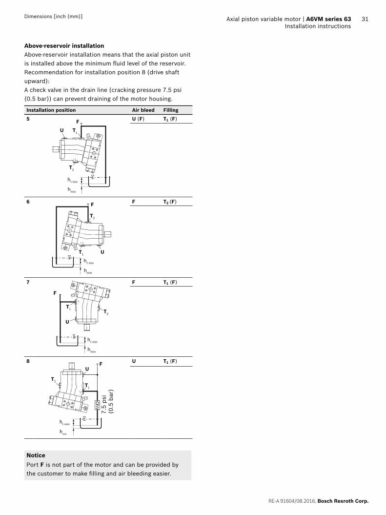
Above-reservoir installationAbove-reservoir installation means that the axial piston unit is installed above the minimum fluid level of the reservoir.Recommendation for installation position 8 (drive shaft upward):A check valve in the drain line (cracking pressure 7.5 psi (0.5 bar)) can prevent draining of the motor housing.
Installation position Air bleed Filling
5
T2
T1UF
ht min
hmin
U (F) T1 (F)
6
ht min
hmin
T2
T1 U
F F T2 (F)
7
T2
T1
U
F
ht min
hmin
F T1 (F)
8
7.5
psi
(0.5
bar
)
ht min
hmin
T2T1
UF U T1 (F)
NoticePort F is not part of the motor and can be provided bythe customer to make filling and air bleeding easier.

Bosch Rexroth Corp., RE-A 91604/08.2016
32 A6VM series 63 | Axial piston variable motorProject planning notes
Project planning notes
The motor A6VM is designed to be used in open and closed circuits.
The project planning, installation and commissioning of the axial piston unit requires the involvement of quali-fied skilled person.
Before using the axial piston unit, please read the cor-responding instruction manual completely and thor-oughly. If necessary, these can be requested from Bosch Rexroth.
Before finalizing your design, request a binding installa-tion drawing.
The data and notes contained herein must be adhered to.
For safety reasons, control systems with beginning of control at Vg min (e.g. HA) are not permissible for winch drives (e.g. anchor winches)!
Depending on the operating condition of the axial piston unit (operating pressure, fluid temperature), the charac-teristic may shift.
Preservation: Our axial piston units are supplied as standard with preservative protection for a maximum of 12 months. If longer preservative protection is required (maximum 24 months), please specify this in plain text when placing your order. The preservation times apply under optimal storage conditions, details of these condi-tions can be found in the data sheet 90312 or the instruction manual.
Not all variants of the product are approved for use in safety functions according to ISO 13849. Please consult the responsible contact person at Bosch Rexroth if you require reliability parameters (e.g. MTTFd) for functional safety.
Depending on the type of control used, electromagnetic effects can be produced when using solenoids. Applying the recommended direct voltage signal (DC) to sole-noids does not create electromagnetic interference (EMI) nor is the solenoid affected by EMI. Electromagnetic interference (EMI) potential exists when operating and controlling a proportional electro-hydraulic coil with a Pulse Width Modulated (PWM) signal. Appropriate testing and measures should be taken by the machine manufacturer to ensure other components or operators (e.g. with pacemaker) are not affected by this potential.
Please note the details regarding the tightening torques of port threads and other threaded joints
Working ports – The ports and fixing threads are designed for the
specified peak pressure. The machine or system manufacturer must ensure that the connecting ele-ments and lines correspond to the specified operat-ing conditions (pressure, volume flow, hydraulic fluid, temperature) with the required safety factors.
– The service and function ports are only designed to accommodate hydraulic lines

RE-A 91604/08.2016, Bosch Rexroth Corp.
Axial piston variable motor | A6VM series 63 Safety instructions
33 Axial piston variable motor | A6VM series 63
Safety instructions
During and shortly after operation, there is a risk of burns on the axial piston unit and especially on the solenoids. Take appropriate safety measures (e.g., by wearing protective clothing).
Moving parts in control equipment (e.g. valve pistons) can, under certain circumstances get blocked in position as a result of contamination (e.g. impure hydraulic fluid, abrasion, or residual dirt from components). As a result, the flow of hydraulic fluid and the build-up of momen-tum in the axial piston unit can no longer meet the operator's specifications. Even the use of various filter elements (external or internal flow filtering) cannot rule out errors, but can only help minimize risks. The machine/system manufacturer must check whether additional measures are required on the machine for the relevant application in order to bring the powered load into a safe position (e.g. safe stop) and ensure any measures are properly put into practice.
In certain conditions, moving parts in high pressure relief valves might get stuck in an undefined position due to contamination. This can result in restriction or loss of load holding functions in lifting winches. There-fore it is the machine and/or system manufacturers responsibility to make sure that the load can always be put in a safe mode if needed. Also, he needs to ensure that these measures are properly implemented.
When using the axial piston motor in winch drives, make certain that the technical limit values are not exceeded under all operating conditions. If the axial piston motor is extremely overloaded (e.g., if the maximum permis-sible rotational speeds are exceeded during weighing of the anchor while the ship is in motion), the rotary group may be damaged and, in the worst case, the axial piston motor may burst. The machine manufacturer / system manufacturer is to undertake additional measures, up to and including encapsulation.
34 A6VM series 63 | Axial piston variable motorSafety instructions
Bosch Rexroth Corp., RE-A 91604/08.2016
Bosch Rexroth CorporationMobile Applications8 Southchase CourtFountain Inn, SC 29644-9018, USATelephone (864) 967-2777Facsimile (864) 967-8900www.boschrexroth-us.com
© Bosch Rexroth AG 2016. All rights reserved, also regarding any disposal, exploitation, reproduction, editing, distribution, as well as in the event of applications for industrial property rights. The data specified within only serves to describe the product. No statements concerning a certain condition or suitability for a certain application can be derived from our information. The information given does not release the user from the obligation of own judgment and verification. It must be remembered that our products are subject to a natural process of wear and aging.

RE-A 91604/08.2016, Bosch Rexroth Corp.
Axial piston variable motor | A6VM series 63 Safety instructions
35Dimensions [inch (mm)]

36
Bosch Rexroth Corp., RE-A 91604/08.2016
Bosch Rexroth CorporationMobile Applications8 Southchase CourtFountain Inn, SC 29644-9018, USATelephone (864) 967-2777Facsimile (864) 967-8900www.boschrexroth-us.com
© Bosch Rexroth AG 2016. All rights reserved, also regarding any disposal, exploitation, reproduction, editing, distribution, as well as in the event of applications for industrial property rights. The data specified within only serves to describe the product. No statements concerning a certain condition or suitability for a certain application can be derived from our information. The information given does not release the user from the obligation of own judgment and verification. It must be remembered that our products are subject to a natural process of wear and aging.
A6VM series 63 | Axial piston variable motorSafety instructions