axial bearing capacity of socketed single cast-in-place piles · stabilize the walls of the bored...
TRANSCRIPT
The Japanese Geotechnical Society
Soils and Foundations
Soils and Foundations 2012;52(1):59–68
0038-0
hosting
Peer re
doi:10.
nCor
E-m
mkirki
806 & 20
by Elsev
view und
1016/j.san
Pr
respondi
ail addre
t@yildiz.
www.sciencedirect.comjournal homepage: www.elsevier.com/locate/sandf
Axial bearing capacity of socketed single cast-in-place piles
Cem Akgunern, Mustafa Kirkit
Yildiz Technical University, Civil Engineering Department, Davutpas-a, Esenler, 34220 _Istanbul, Turkey
Available online 7 February 2012
Abstract
In this paper, a comparison is made of the axial bearing capacities estimated with pile load tests and empirical methods for seven rock-
socketed single cast-in-place piles constructed in Turkey. The unconfined compressive strength of rock, obtained from pressuremeter
tests, is used in the empirical correlations. It is commonly assumed that axial loads applied at the top of a socketed pile are transferred to
the sides of the socket until a certain displacement is reached and that the end bearing capacity contributes only after this threshold
displacement is exceeded. In practice, however, due to typically small displacements occurring in rock sockets, most, if not all, of the
axial capacity is estimated to derive from the side shear. The limit displacement up to which the side frictional capacity of a socketed pile
governs and the end bearing capacity starts mobilizing is examined, and no such threshold value is observed based on the findings of this
study. Nevertheless, the bearing capacities obtained from the empirical correlations agree reasonably well with those calculated from pile
load tests, when a systematic approach for estimating the threshold value from pile load tests is utilized and the unconfined compressive
strength of socketed rocks can be estimated within reasonable accuracy applying actual field conditions.
& 2012. The Japanese Geotechnical Society. Production and hosting by Elsevier B.V. All rights reserved.
Keywords: Base resistance; Bearing capacity; Empirical methods; Mobilization capacity; Pile load test; Side shear resistance; Socketed cast-in-place pile;
Vertical load (IGC:E04/G02)
1. Introduction
Rock-socketed cast-in-place piles are typically selectedwhen the large loads of superstructures, such as high-risebuildings, tower structures and bridge footings/abutments,need to be transferred to competent bearing strata so asto restrict deformations within the serviceability limits.Furthermore, the use of drilled piles socketed into rock as
12. The Japanese Geotechnical Society. Production and
ier B.V. All rights reserved.
er responsibility of The Japanese Geotechnical Society
df.2012.01.012
oduction and hosting by Elsevier
ng author.
sses: [email protected] (C. Akguner),edu.tr (M. Kirkit).
foundation structures is one of the best solutions whenlayers of loose soil overlie bedrock at shallow depths. Inthese cases, considerable bearing capacity can be ensuredby the shaft friction in rock, even with small pile displace-ments (Carrubba, 1997). Piles can be classified based onthe expected governing load-transfer mechanism (CFEM,2006)
(a)
at the tip of the pile, (b) on the pile shaft, or (c) both at the tip and on the shaft.The axial load carrying capacity of rock-socketed cast-in-place piles can be estimated by applying static analyses,
information/data collected from pile load tests, numericalmethods and empirical approaches. Load tests are con-ducted to determine the in situ bearing capacity and theload–deformation behavior of piles. Pile load testingprovides the most reliable information for the design,because it is a large-scale, if not full-scale, model for thebehavior of a designed pile in actual soil conditions.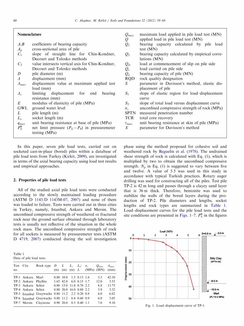
Nomenclature
A,B coefficients of bearing capacityAp cross-sectional area of pileC1 slope of straight line for Chin-Kondner,
Decourt and Tolosko methodsC2 value intersects vertical axis for Chin-Kondner,
Decourt and Tolosko methodsD pile diameter (m)D displacement (mm)Dmax displacement value at maximum applied test
load (mm)Ds limiting displacement for end bearing
resistance (mm)E modulus of elasticity of pile (MPa)GWL ground water levelL pile length (m)Ls socket length (m)qmax unit bearing resistance at base of pile (MPa)PLn net limit pressure (PL�P0) in pressuremeter
testing (MPa)
Qmax maximum load applied in pile load test (MN)Q applied load in pile load test (MN)Q1 bearing capacity calculated by pile load
test (MN)Q2 bearing capacity calculated by empirical corre-
lations (MN)Qfs load at commencement of slip on pile sideQs load carried on pile sideQu bearing capacity of pile (MN)RQD rock quality designationS parameter in Davisson’s method, elastic dis-
placement of pileS1 slope of elastic region for load–displacement
curveS2 slope of total load versus displacement curvesc unconfined compressive strength of rock (MPa)SPTN measured penetration numberTCR total core recoverytmax unit bearing resistance at skin of pile (MPa)X parameter for Davisson’s method
C. Akguner, M. Kirkit / Soils and Foundations 52 (2012) 59–6860
In this paper, seven pile load tests, carried out onsocketed cast-in-place (bored) piles within a database ofpile load tests from Turkey (Kirkit, 2009), are investigatedin terms of the axial bearing capacity using load test resultsand empirical approaches.
2. Properties of pile load tests
All of the studied axial pile load tests were conductedaccording to the slowly maintained loading procedure(ASTM D 1143/D 1143M-07, 2007) and none of themwas loaded to failure. Tests were carried out in three citiesin Turkey, namely, Istanbul, Ankara and Mersin. Theunconfined compressive strength of weathered or fracturedrock near the ground surface obtained through laboratorytests is usually not reflective of the situation in the wholerock mass. The unconfined compressive strength of rockfor all sockets is measured by pressuremeter tests (ASTMD 4719, 2007) conducted during the soil investigation
Table 1
Data of pile load tests.
Test
no.
City Rock type D
(m)
L
(m)
Ls
(m)
Ls/
L
sc
(MPa)
Qmax
(MN)
Dmax
(mm)
TP-1 Ankara Marl 0.80 10.0 1.5 0.15 1.6 5.5 42.10
TP-2 Ankara Phyllite 1.65 42.0 6.0 0.15 1.7 12.0 3.53
TP-3 Ankara Schist 0.80 15.0 11.0 0.70 2.2 8.8 13.75
TP-4 Ankara Schist 0.80 20.0 16.0 0.80 2.2 5.9 3.32
TP-5 _Istanbul Graywacke 0.80 11.2 2.2 0.20 0.8 6.0 6.02
TP-6 _Istanbul Graywacke 0.80 11.2 6.4 0.60 0.9 6.0 3.05
TP-7 Mersin Claystone 0.90 20.0 8.5 0.40 1.1 7.0 9.10
phase using the method proposed for cohesive soil andweathered rock by Baguelin et al. (1978). The undrainedshear strength of rock is calculated with Eq. (1), which ismultiplied by two to obtain the unconfined compressivestrength. Np in Eq. (1) is suggested to vary between fiveand twelve. A value of 5.5 was used in this study inaccordance with typical Turkish practices. Rotary augerdrilling was used for constructing all of the piles. Test pileTP-2 is 42 m long and passes through a clayey sand layerthat is 36 m thick. Therefore, bentonite was used tostabilize the walls of the bored layers during the pro-duction of TP-2. Pile diameters and lengths, socketlengths and rock types are summarized in Table 1.Load–displacement curves for the pile load tests and thesite conditions are presented in Figs. 1–7. PL
n in the figures
Fig. 1. Load–displacement curve of TP-1.
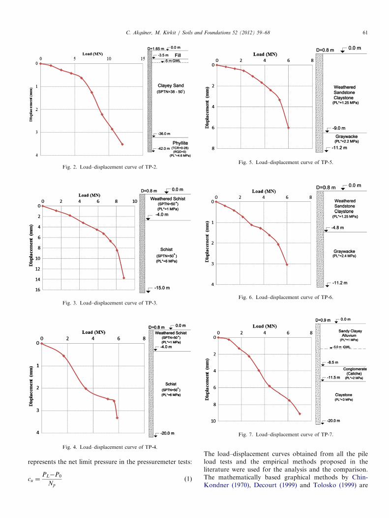
Fig. 2. Load–displacement curve of TP-2.
Fig. 3. Load–displacement curve of TP-3.
Fig. 4. Load–displacement curve of TP-4.
Fig. 5. Load–displacement curve of TP-5.
Fig. 6. Load–displacement curve of TP-6.
Fig. 7. Load–displacement curve of TP-7.
C. Akguner, M. Kirkit / Soils and Foundations 52 (2012) 59–68 61
represents the net limit pressure in the pressuremeter tests:
cu ¼PL�P0
Np
ð1Þ
The load–displacement curves obtained from all the pileload tests and the empirical methods proposed in theliterature were used for the analysis and the comparison.The mathematically based graphical methods by Chin-Kondner (1970), Decourt (1999) and Tolosko (1999) are
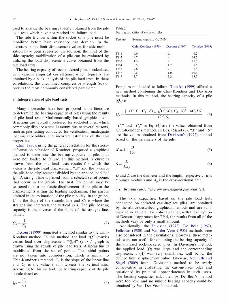
Table 2
Bearing capacities of socketed piles.
Test no. Bearing capacity Qu (MN)
Chin-Kondner (1970) Decourt (1999) Tolosko (1999)
TP-1 6.0 6.1 6.2
TP-2 14.7 14.1 14.7
TP-3 11.5 12.1 11.5
TP-4 8.5 11.7 8.6
TP-5 7.8 7.1 7.8
TP-6 10.5 11.0 10.4
TP-7 13.7 13.2 13.7
C. Akguner, M. Kirkit / Soils and Foundations 52 (2012) 59–6862
used to analyze the bearing capacity obtained from the pileload tests which have not reached the failure load.
The side friction within the socket of a pile must bemobilized before base resistance can develop. In theliterature, some limit displacement values for side mobili-zation have been suggested. In addition, the limit of theside capacity mobilization of a pile can be evaluated byutilizing the load–displacement curve obtained from thepile load tests.
The bearing capacity of rock-socketed piles is calculatedwith various empirical correlations, which typically areobtained by a back analysis of the pile load tests. In thesecorrelations, the unconfined compressive strength (sc) ofrock is the most commonly considered parameter.
3. Interpretation of pile load tests
Many approaches have been proposed in the literatureto determine the bearing capacity of piles using the resultsof pile load tests. Mathematically based graphical con-structions are typically preferred for socketed piles, whichcommonly displace a small amount due to several reasons,such as pile testing conducted for verification, inadequateloading capabilities and incorrect estimates of the soilproperties.
Chin (1970), using the general correlation for the stress–deformation behavior of Kondner, proposed a graphicalmethod to determine the bearing capacity of piles thatwere not loaded to failure. In this method, a curve isdrawn from the pile load tests results for which thex-axis is the pile head displacement ‘‘D’’ and the y-axis isthe pile head displacement divided by the applied load ‘‘D/Q’’. A straight line is passed from a selected set of pointsthat occur in the graph. The first few points may bescattered due to the elastic displacement of the pile or thedisplacements within the loading mechanism. This part isomitted in the estimation of the pile capacity. In the graph,C1 is the slope of the straight line and C2 is where thestraight line intersects the vertical axis. The pile bearingcapacity is the inverse of the slope of the straight line,namely
Qu ¼1
C1ð2Þ
Decourt (1999) suggested a method similar to the Chin-Kondner method. In this method, the load ‘‘Q’’ (x-axis)versus load over displacement ‘‘Q/D’’ (y-axis) graph isdrawn using the results of pile load tests. A linear line isestablished from the set of points. The initial pointsare not taken into consideration, which is similar toChin-Kondner’s method. C1 is the slope of the linear lineand C2 is the value that intersects the vertical axis.According to this method, the bearing capacity of the pileis calculated as
Qu ¼C2
C1ð3Þ
For piles not loaded to failure, Tolosko (1999) offered anew method combining the Chin-Kondner and Davissonmethods. In this method, the bearing capacity of a pile(Qu) is
Qu ¼½�ðC1XþC2�SÞ7
ffiffiffiffiffiffiffiffiffiffiffiffiffiffiffiffiffiffiffiffiffiffiffiffiffiffiffiffiffiffiffiffiðC1XþC2�SÞ2
qþ4C1XS�
ð2C1SÞð4Þ
‘‘C1’’ and ‘‘C2’’ in Eq. (4) are the values obtained fromChin-Kondner’s method. In Eqs. (5)and (6), ‘‘X’’ and ‘‘S’’are the values obtained from Davisson’s (1972) methodbased on the parameters of the pile:
X ¼ 4þD
120ð5Þ
S¼L
EAp
ð6Þ
D and L are the diameter and the length, respectively, E isYoung’s modulus and Ap is the cross-sectional area.
3.1. Bearing capacities from investigated pile load tests
The axial capacities, based on the pile load testsconducted on socketed cast-in-place piles, are obtainedby the above-described graphical methods and are sum-marized in Table 2. It is noticeable that, with the exceptionof Decourt’s approach for TP-4, the results from all of themethods vary by only a small amount.Additionally, the Davisson (1972), De Beer (1967),
Fellenius (1980) and Van der Veen (1953) methods werealso considered in the calculations. However, these meth-ods were not useful for obtaining the bearing capacity ofthe analyzed rock-socketed piles. In Davisson’s method,the applied load (Q) was large and the correspondingdisplacement (D) was very small, i.e., well below thedefined limit displacement value. Likewise, NeSmith andSiegel (2009) found Davisson’s method to be overlyconservative in evaluating the cast-in-place piles andquestioned its practical appropriateness in such cases.The bearing capacities calculated by De Beer’s methodwere too low, and no unique bearing capacity could beobtained by Van Der Veen’s method.
C. Akguner, M. Kirkit / Soils and Foundations 52 (2012) 59–68 63
4. Load transfer mechanism of socketed piles
Three of the considered test piles (TP-1, TP-2 and TP-7)were socketed into strong rock layers underlying muchweaker soil layers, while the rest of the piles (TP-3, TP-4,TP-5 and TP-6) were penetrated through weathered rockbefore reaching competent rock layers. In accordance withthe common practical approach (CFEM, 2006; Das, 2011),any possible influence from the layers above the socketedsurfaces to the axial capacity is disregarded in this paperdue to the typically large differences in rigidity betweensockets and overlying layers as well as redundancy.
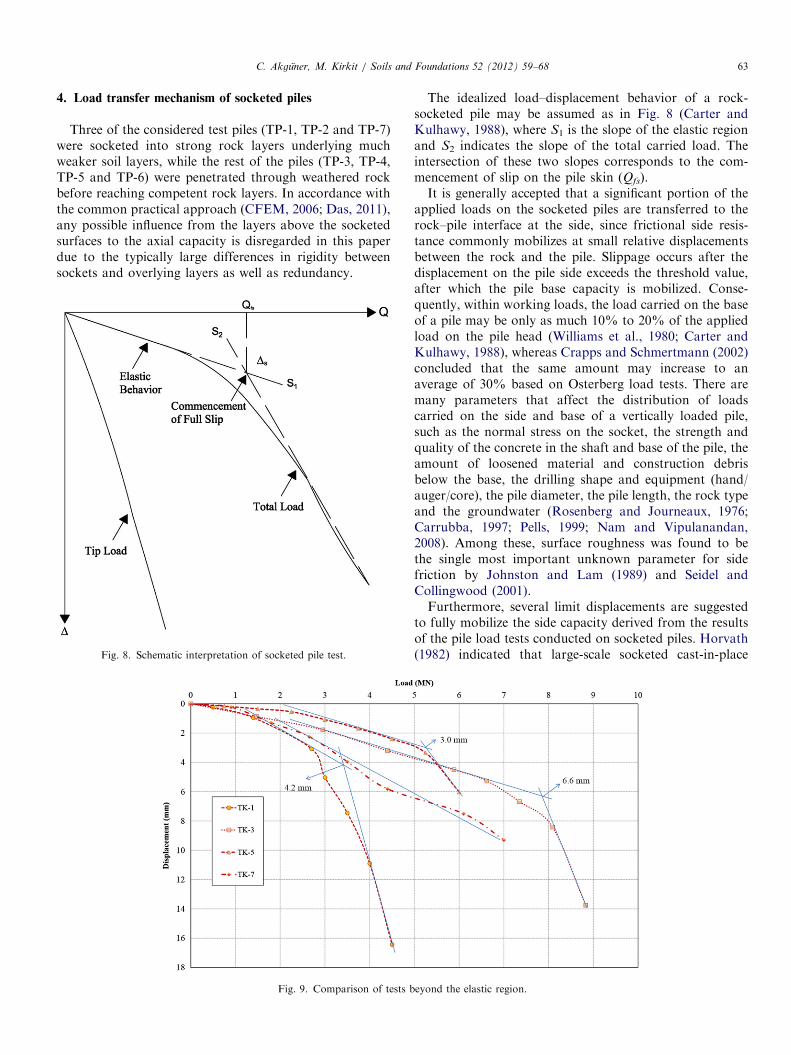
Fig. 8. Schematic interpretation of socketed pile test.
Fig. 9. Comparison of tests b
The idealized load–displacement behavior of a rock-socketed pile may be assumed as in Fig. 8 (Carter andKulhawy, 1988), where S1 is the slope of the elastic regionand S2 indicates the slope of the total carried load. Theintersection of these two slopes corresponds to the com-mencement of slip on the pile skin (Qfs).It is generally accepted that a significant portion of the
applied loads on the socketed piles are transferred to therock–pile interface at the side, since frictional side resis-tance commonly mobilizes at small relative displacementsbetween the rock and the pile. Slippage occurs after thedisplacement on the pile side exceeds the threshold value,after which the pile base capacity is mobilized. Conse-quently, within working loads, the load carried on the baseof a pile may be only as much 10% to 20% of the appliedload on the pile head (Williams et al., 1980; Carter andKulhawy, 1988), whereas Crapps and Schmertmann (2002)concluded that the same amount may increase to anaverage of 30% based on Osterberg load tests. There aremany parameters that affect the distribution of loadscarried on the side and base of a vertically loaded pile,such as the normal stress on the socket, the strength andquality of the concrete in the shaft and base of the pile, theamount of loosened material and construction debrisbelow the base, the drilling shape and equipment (hand/auger/core), the pile diameter, the pile length, the rock typeand the groundwater (Rosenberg and Journeaux, 1976;Carrubba, 1997; Pells, 1999; Nam and Vipulanandan,2008). Among these, surface roughness was found to bethe single most important unknown parameter for sidefriction by Johnston and Lam (1989) and Seidel andCollingwood (2001).Furthermore, several limit displacements are suggested
to fully mobilize the side capacity derived from the resultsof the pile load tests conducted on socketed piles. Horvath(1982) indicated that large-scale socketed cast-in-place
eyond the elastic region.

C. Akguner, M. Kirkit / Soils and Foundations 52 (2012) 59–6864
piles should undergo an average relative displacement of5.0 mm, whereas Rosenberg and Journeaux (1976) sug-gested a limit value of 6.35 mm (0.25 in.). NCHRP (2006)found that the side resistance typically reaches a maximumdisplacement in the range of 5–10 mm. Additionally, forsocketed piles installed in Turkey, the entire load is, albeitconservatively, assumed to be carried solely by the sidefriction when the displacement is less than 10 mm(Yıldırım, 2009). Similarly, in the Mumbai Region ofIndia, where weathered rock such as basalt, breccia andtuff are common, Basarkar and Dewaikar (2006)
Table 3
Relationship between Ds, D and L.
Test no. Ds (mm) Ds/D (%) Ds/L (%)
TP-1 4.2 5.25 0.42
TP-3 6.6 8.25 0.44
TP-5 3.0 3.75 0.27
Table 4
‘‘A’’ and ‘‘B’’ values for side shear resistance.
Method A B
Rosenberg and Journeaux (1976) 0.375 0.515
Rowe and Armitage (1987) 0.45 0.5
Rowe and Armitage (1987) 0.6 0.5
Horvath et al. (1983) 0.2–0.3 1
Meigh and Wolski (1979) 0.22 0.6
Gupton and Logan (1984) 0.2 1
Reynolds and Kaderabek (1980) 0.3 1
Toh et al. (1989) 0.25 1
Carter and Kulhawy (1988) 0.2 0.5
Zhang and Einstein (1998) 0.4 0.5
Zhang and Einstein (1998) 0.8 0.5
Fig. 10. Empirical methods
calculated a ‘‘critical’’ displacement value of 10 mm tomobilize the maximum side shear.Four of the seven load tests considered in this study (TP-
1, TP-3, TP-5 and TP-7) exceeded 5 mm. No significantbreak point could be located for TP-7. For TP-1, TP-3 andTP-5, the limit displacements, where slippage is assumed tooccur, were obtained from pile load test results, assuggested by Carter and Kulhawy (1988) (Fig. 9). Due tothe large variability, it is not possible to recommend asingle limiting displacement for the commencement of thebase resistance. The ratios of the limiting displacement (Ds)to the pile diameter (D) and the length (L) are given inTable 3.
5. Empirical methods
Empirical methods generally suggest separate side andbase resistance correlations, although there is also ananalytical approach that incorporates the soil couplingeffect (Seol et al., 2009). The approaches proposed byvarious researchers can be generalized, as in Eq. (7), where
Description Reference
Rosenberg and Journeaux (1976)
R1, R2 and R3 rough sockets Rowe and Armitage (1987)
R4 rough sockets Rowe and Armitage (1987)
A¼0.25 (average) Horvath et al. (1983)
Zhang (2004)
Zhang (2004)
Zhang (2004)
Zhang (2004)
Carter and Kulhawy (1988)
Smooth socket Zhang and Einstein (1998)
Rough socket Zhang and Einstein (1998)
for side shear resistance.
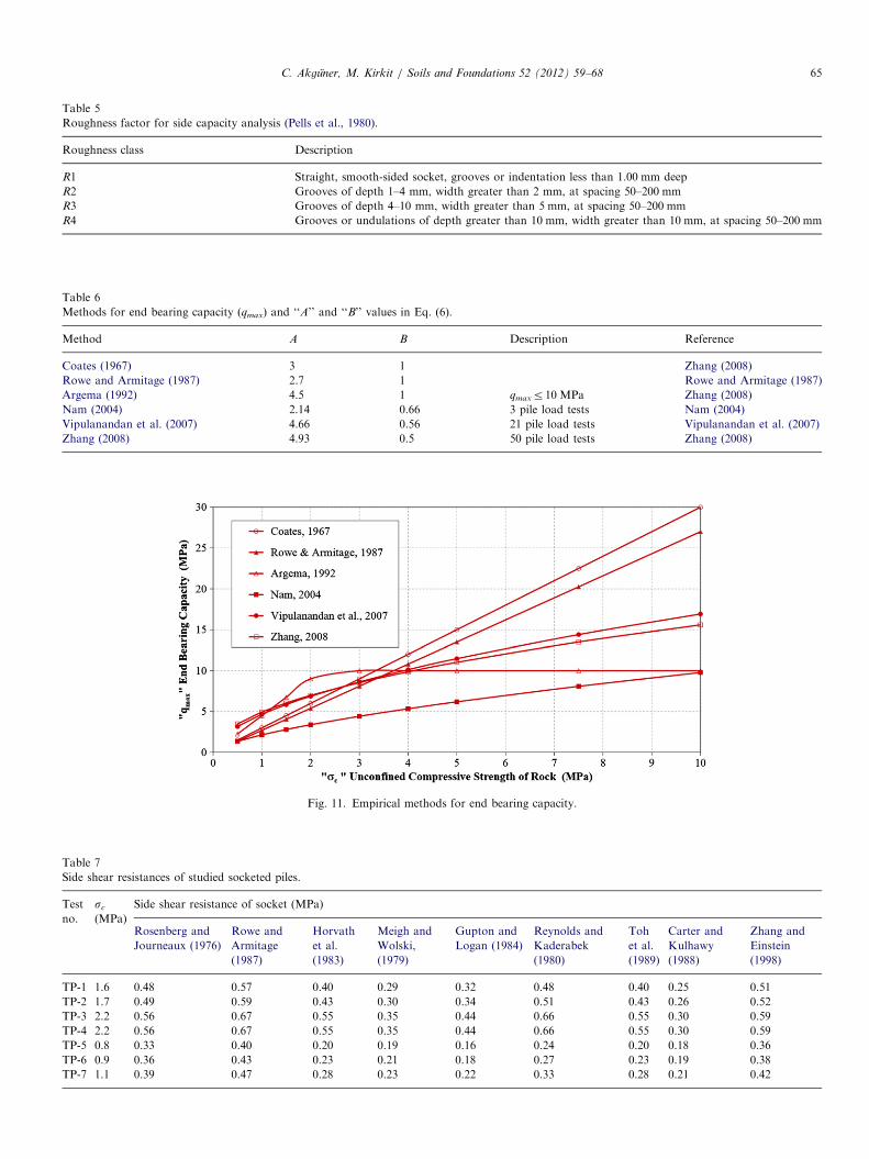
Table 5
Roughness factor for side capacity analysis (Pells et al., 1980).
Roughness class Description
R1 Straight, smooth-sided socket, grooves or indentation less than 1.00 mm deep
R2 Grooves of depth 1–4 mm, width greater than 2 mm, at spacing 50–200 mm
R3 Grooves of depth 4–10 mm, width greater than 5 mm, at spacing 50–200 mm
R4 Grooves or undulations of depth greater than 10 mm, width greater than 10 mm, at spacing 50–200 mm
Table 6
Methods for end bearing capacity (qmax) and ‘‘A’’ and ‘‘B’’ values in Eq. (6).
Method A B Description Reference
Coates (1967) 3 1 Zhang (2008)
Rowe and Armitage (1987) 2.7 1 Rowe and Armitage (1987)
Argema (1992) 4.5 1 qmaxr10 MPa Zhang (2008)
Nam (2004) 2.14 0.66 3 pile load tests Nam (2004)
Vipulanandan et al. (2007) 4.66 0.56 21 pile load tests Vipulanandan et al. (2007)
Zhang (2008) 4.93 0.5 50 pile load tests Zhang (2008)
Fig. 11. Empirical methods for end bearing capacity.
Table 7
Side shear resistances of studied socketed piles.
Test
no.
sc
(MPa)
Side shear resistance of socket (MPa)
Rosenberg and
Journeaux (1976)
Rowe and
Armitage
(1987)
Horvath
et al.
(1983)
Meigh and
Wolski,
(1979)
Gupton and
Logan (1984)
Reynolds and
Kaderabek
(1980)
Toh
et al.
(1989)
Carter and
Kulhawy
(1988)
Zhang and
Einstein
(1998)
TP-1 1.6 0.48 0.57 0.40 0.29 0.32 0.48 0.40 0.25 0.51
TP-2 1.7 0.49 0.59 0.43 0.30 0.34 0.51 0.43 0.26 0.52
TP-3 2.2 0.56 0.67 0.55 0.35 0.44 0.66 0.55 0.30 0.59
TP-4 2.2 0.56 0.67 0.55 0.35 0.44 0.66 0.55 0.30 0.59
TP-5 0.8 0.33 0.40 0.20 0.19 0.16 0.24 0.20 0.18 0.36
TP-6 0.9 0.36 0.43 0.23 0.21 0.18 0.27 0.23 0.19 0.38
TP-7 1.1 0.39 0.47 0.28 0.23 0.22 0.33 0.28 0.21 0.42
C. Akguner, M. Kirkit / Soils and Foundations 52 (2012) 59–68 65
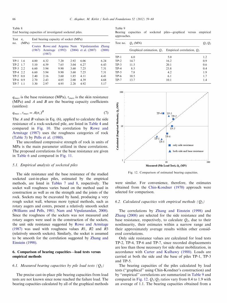
Table 8
End bearing capacities of investigated socketed piles.
Test
no.
sc
(MPa)
End bearing capacity of socket (MPa)
Coates
(1967)
Rowe and
Armitage
(1987)
Argema
(1992)
Nam
(2004)
Vipulanandan
et al. (2007)
Zhang
(2008)
TP-1 1.6 4.80 4.32 7.20 2.92 6.06 6.24
TP-2 1.7 5.10 4.59 7.65 3.04 6.27 6.43
TP-3 2.2 6.60 5.94 9.90 3.60 7.25 7.31
TP-4 2.2 6.60 5.94 9.90 3.60 7.25 7.31
TP-5 0.8 2.40 2.16 3.60 1.85 4.11 4.41
TP-6 0.9 2.70 2.43 4.05 2.00 4.39 4.68
TP-7 1.1 3.30 2.97 4.95 2.28 4.92 5.17
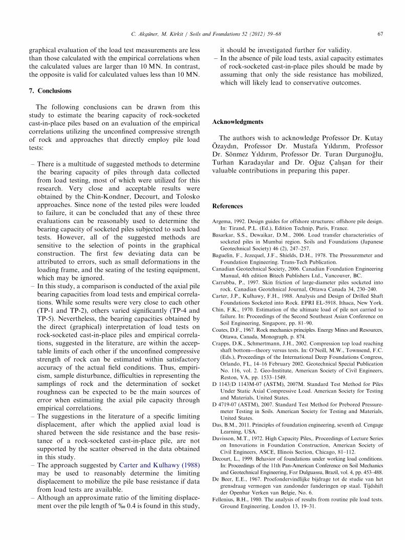
Table 9
Bearing capacities of socketed piles—graphical versus empirical
approaches.
Test no. Qu (MN) Q1/Q2
Graphical estimation, Q1 Empirical correlation, Q2
TP-1 6.0 5.0 1.2
TP-2 14.7 16.2 0.9
TP-3 11.5 20.1 0.6
TP-4 8.5 23.8 0.4
TP-5 7.8 4.2 1.9
TP-6 10.5 6.1 1.7
TP-7 13.7 10.1 1.4
Fig. 12. Comparison of estimated bearing capacities.
C. Akguner, M. Kirkit / Soils and Foundations 52 (2012) 59–6866
qmax is the base resistance (MPa), tmax is the skin resistance(MPa) and A and B are the bearing capacity coefficients(unitless):
qmax ; tmax ¼AðscÞB
ð7Þ
The A and B values in Eq. (6), applied to calculate the sideresistance of a rock-socketed pile, are listed in Table 4 andcompared in Fig. 10. The correlation by Rowe andArmitage (1987) uses the roughness categories of rock(Table 5) by Pells et al. (1980).
The unconfined compressive strength of rock in units ofMPa is the main parameter utilized in these correlations.The proposed correlations for the base resistance are givenin Table 6 and compared in Fig. 11.
5.1. Empirical analysis of socketed piles
The side resistance and the base resistance of the studiedsocketed cast-in-place piles, estimated by the empiricalmethods, are listed in Tables 7 and 8, respectively. Thesocket wall roughness varies based on the method used inconstruction as well as on the strength and the joints of therock. Sockets may be excavated by hand, producing a veryrough socket wall, whereas more typical methods, such asrotary augers and corers, present a relatively smooth socket(Williams and Pells, 1981; Nam and Vipulanandan, 2008).Since the roughness of the sockets was not measured androtary augers were used in the construction of the sockets,the unit side resistance suggested by Rowe and Armitage(1987) was used with roughness values R1, R2 and R3(relatively smooth sockets). Similarly, the socket is assumedto be smooth for the correlation suggested by Zhang andEinstein (1998).
6. Comparison of bearing capacities—load tests versus
empirical methods
6.1. Measured bearing capacities by pile load tests (Q1)
The precise cast-in-place pile bearing capacities from loadtests are not known since none reached the failure load. Thebearing capacities calculated by all of the graphical methods
were similar. For convenience, therefore, the estimatesobtained from the Chin-Kondner (1970) approach wereselected for comparison.
6.2. Calculated capacities with empirical methods (Q2)
The correlations by Zhang and Einstein (1998) andZhang (2008) are selected for the side resistance and thebase resistance, respectively, to calculate Q2, due to theirnonlinearity, their estimates within a narrow range andtheir approximately average results within other consid-ered correlations.Only side resistance values are calculated for load tests
TP-2, TP-4, TP-6 and TP-7, since recorded displacementsare less than those necessary for side shear mobilization, inaccordance with Carter and Kulhawy (1988). Loads arecarried at both the side and the base of piles TP-1, TP-3and TP-5.The bearing capacities of the piles calculated by load
tests (‘‘graphical’’ using Chin-Kondner’s construction) andby ‘‘empirical’’ correlations are summarized in Table 9 andcompared in Fig. 12. Q1/Q2 ratios vary from 0.4 to 1.9 withan average of 1.1. The bearing capacities obtained from a
C. Akguner, M. Kirkit / Soils and Foundations 52 (2012) 59–68 67
graphical evaluation of the load test measurements are lessthan those calculated with the empirical correlations whenthe calculated values are larger than 10 MN. In contrast,the opposite is valid for calculated values less than 10 MN.
7. Conclusions
The following conclusions can be drawn from thisstudy to estimate the bearing capacity of rock-socketedcast-in-place piles based on an evaluation of the empiricalcorrelations utilizing the unconfined compressive strengthof rock and approaches that directly employ pile loadtests:
–
There is a multitude of suggested methods to determinethe bearing capacity of piles through data collectedfrom load testing, most of which were utilized for thisresearch. Very close and acceptable results wereobtained by the Chin-Kondner, Decourt, and Toloskoapproaches. Since none of the tested piles were loadedto failure, it can be concluded that any of these threeevaluations can be reasonably used to determine thebearing capacity of socketed piles subjected to such loadtests. However, all of the suggested methods aresensitive to the selection of points in the graphicalconstruction. The first few deviating data can beattributed to errors, such as small deformations in theloading frame, and the seating of the testing equipment,which may be ignored.–
In this study, a comparison is conducted of the axial pilebearing capacities from load tests and empirical correla-tions. While some results were very close to each other(TP-1 and TP-2), others varied significantly (TP-4 andTP-5). Nevertheless, the bearing capacities obtained bythe direct (graphical) interpretation of load tests onrock-socketed cast-in-place piles and empirical correla-tions, suggested in the literature, are within the accep-table limits of each other if the unconfined compressivestrength of rock can be estimated within satisfactoryaccuracy of the actual field conditions. Thus, empiri-cism, sample disturbance, difficulties in representing thesamplings of rock and the determination of socketroughness can be expected to be the main sources oferror when estimating the axial pile capacity throughempirical correlations.–
The suggestions in the literature of a specific limitingdisplacement, after which the applied axial load isshared between the side resistance and the base resis-tance of a rock-socketed cast-in-place pile, are notsupported by the scatter observed in the data obtainedin this study.–
The approach suggested by Carter and Kulhawy (1988)may be used to reasonably determine the limitingdisplacement to mobilize the pile base resistance if datafrom load tests are available.–
Although an approximate ratio of the limiting displace-ment over the pile length of % 0.4 is found in this study,it should be investigated further for validity.
– In the absence of pile load tests, axial capacity estimatesof rock-socketed cast-in-place piles should be made byassuming that only the side resistance has mobilized,which will likely lead to conservative outcomes.Acknowledgments
The authors wish to acknowledge Professor Dr. KutayOzaydın, Professor Dr. Mustafa Yıldırım, ProfessorDr. Sonmez Yıldırım, Professor Dr. Turan Durgunoglu,Turhan Karadayılar and Dr. Oguz C- alıs-an for theirvaluable contributions in preparing this paper.
References
Argema, 1992. Design guides for offshore structures: offshore pile design.
In: Tirand, P.L. (Ed.), Edition Technip, Paris, France.
Basarkar, S.S., Dewaikar, D.M., 2006. Load transfer characteristics of
socketed piles in Mumbai region. Soils and Foundations (Japanese
Geotechnical Society) 46 (2), 247–257.
Baguelin, F., Jezequel, J.F., Shields, D.H., 1978. The Pressuremeter and
Foundation Engineering. Trans-Tech Publication.
Canadian Geotechnical Society, 2006. Canadian Foundation Engineering
Manual, 4th edition Bitech Publishers Ltd., Vancouver, BC.
Carrubba, P., 1997. Skin friction of large-diameter piles socketed into
rock. Canadian Geotehnical Journal, Ottawa Canada 34, 230–240.
Carter, J.P., Kulhawy, F.H., 1988. Analysis and Design of Drilled Shaft
Foundations Socketed into Rock. EPRI EL-5918. Ithaca, New York.
Chin, F.K., 1970. Estimation of the ultimate load of pile not carried to
failure. In: Proceedings of the Second Southeast Asian Conference on
Soil Engineering, Singapore, pp. 81–90.
Coates, D.F., 1967. Rock mechanics principles. Energy Mines and Resources,
Ottawa, Canada, Monograph, p. 874.
Crapps, D.K., Schmertmann, J.H., 2002. Compression top load reaching
shaft bottom—theory versus tests. In: O’Neill, M.W., Townsend, F.C.
(Eds.), Proceedings of the International Deep Foundations Congress,
Orlando, FL, 14–16 February 2002. Geotechnical Special Publication
No. 116, vol. 2. Geo-Institute, American Society of Civil Engineers,
Reston, VA, pp. 1533–1549.
D 1143/D 1143M-07 (ASTM), 2007M. Standard Test Method for Piles
Under Static Axial Compressive Load. American Society for Testing
and Materials, United States.
D 4719-07 (ASTM), 2007. Standard Test Method for Prebored Pressure-
meter Testing in Soils. American Society for Testing and Materials,
United States.
Das, B.M., 2011. Principles of foundation engineering, seventh ed. Cengage
Learning, USA.
Davisson, M.T., 1972. High Capacity Piles,. Proceedings of Lecture Series
on Innovations in Foundation Construction, American Society of
Civil Engineers, ASCE, Illinois Section, Chicago, 81–112.
Decourt, L., 1999. Behavior of foundations under working load conditions.
In: Proceedings of the 11th Pan-American Conference on Soil Mechanics
and Geotechnical Engineering, Foz Dulguassu, Brazil, vol. 4, pp. 453–488.
De Beer, E.E., 1967. Proefondervindlijke bijdrage tot de studie van het
grensdraag vermogen van zandonder funderingen op staal. Tijdshift
der Openbar Verken van Belgie, No. 6.
Fellenius, B.H., 1980. The analysis of results from routine pile load tests.
Ground Engineering, London 13, 19–31.
C. Akguner, M. Kirkit / Soils and Foundations 52 (2012) 59–6868
Gupton, C., Logan, T., 1984. Design guidelines for drilled shafts in weak
rocks of South Florida. In: Proceeding South Florida Annual ASCE
Meeting. ASCE.
Horvath, R.G., 1982. Behavior of Rock-Socketed Drilled Pier Founda-
tions. Ph.D. Thesis. University of Toronto, Toronto.
Horvath, R.G., Kenney, T.C., Kozicki, P., 1983. Methods of improving
the performance of drilled piers in weak rock. Canadian Geotechnical
Journal, Ottawa, Canada 20 (4), 758–772.
Johnston, I.W., Lam, T.S.K., 1989. Shear behavior of regular triangular
concrete/rock joints—analysis. Journal of Geotechnical Engineering,
ASCE 115 (5), 711–727.
Kirkit, M., 2009. Establishing a Data Base of Pile Load Tests Conducted
in Turkey and Analysis of Rock-Socketed Piles within Data Base.
Master Thesis. Yıldız Technical University, Institute of Science,_Istanbul (in Turkish).
Meigh, A.C., Wolski, W., 1979. Design parameters for weak rocks. In:
Proceeding of the seventh European Conference on Soil Mechanics
and Foundation Engineering, vol. 5. British Geotechnical Society,
Brighton, pp. 59–79.
Nam, M.S., 2004. Improved Design for Drilled Shafts in Rock. Ph.D.
Thesis. University of Houston, Houston, TX.
Nam, M.S., Vipulanandan, C., 2008. Roughness and unit side resistances of
drilled shafts socketed in clay shale and limestone. Journal of Geotech-
nical and Geoenvironmental Engineering (ASCE) 134 (9), 1272–1279.
NCHRP Transportation Research Board, 2006. NCHRP SYNTHESIS
360 Rock-Socketed Shafts for Highway Structure Foundations.
NCHRP, Washington.
NeSmith, W.M., Siegel, T.C., 2009. Shortcomings of the Davisson offset
limit applied to axial compressive load tests on cast-in-place piles. In:
Contemporary Topics in Deep Foundations—Geotechnical Special
Publications No. 185. ASCE, pp. 568–574.
Pells, P.J.N., 1999. State of practice for the design of socketed piles in rock.
In: Proceedings of the Eighth Australia New Zealand Conference on
Geomechanics. Australian Geomechanics Society, pp. 307–327.
Pells, P.J.N., Rowe, R.K., Turner, R.M., 1980. An experimental investi-
gation into side shear for socketed piles in sandstone. Proceedings of
the International Conference on Structural Foundations on Rock,
Sydney, Australia 1, 291–302.
Reynolds, R.T., Kaderabek, T.J., 1980. Miami limestone foundation
design and construction. ASCE, New York.
Rosenberg, P., Journeaux, N.L., 1976. Friction and end bearing tests on
bedrock for high capacity socket design. Canadian Geotechnical
Journal, Ottawa, Canada 13, 324–333.
Rowe, R.K., Armitage, H.H., 1987. A design method for drilled piers in soft
rock. Canadian Geotechnical Journal, Ottawa, Canada 24 (1), 126–142.
Seidel, J.P., Collingwood, B., 2001. A new socket roughness factor for
prediction of rock socket shaft resistance. Canadian Geotechnical
Journal, Ottawa, Canada 38, 138–153.
Seol, H., Jeong, S., Cho, S., 2009. Analytical method for load-transfer
characteristics of rock-socketed drilled shafts. Journal of Geo-
technical and Geoenvironmental Engineering (ASCE) 135 (6),
778–789.
Toh, C.T., Ooi, T.A., Chiu, H.K., Chee, S.K., Ting, W.N., 1989. Design
parameters for bored piles in a weathered sedimentary formation. In:
Proceeding 12th International Conference on Soil Mechanics and
Foundation Engineering, Rio de Janerio 2, 1073–1078.
Tolosko, T.A., 1999. Extrapolation of Pile Capacity from Non-Failed
Load Tests. Master of Science in Civil Engineering. University of
Massachusetts, Lowell.
Van der Veen, C., 1953. The bearing capacity of pile. In: Proceedings of
the Third ICSMFE, pp. 84–90.
Vipulanandan, C., Hussain, A., Usluogulari, O., 2007. Parametric study
of open core-hole on the behavior of drilled shafts socketed in soft
rock. In: Proceedings of the Geo-Denver 2007, Geotechnical Special
Publication No. 158. Contemporary Issues in Deep Foundations,
Denver, Colorado, in Cd-Ram.
Williams, A.F., Johnston, I.W., Donald, I.B., 1980. The design of
socketed piles in weak rock. In: Proceedings of the International
Conference on Structural Foundations on Rock, Balkema, Sydney,
Australia, pp. 327–347.
Williams, A.F., Pells, P.J.N., 1981. Side resistance of rock sockets in
sandstone, mudstone and shale. Canadian Geotechnical Journal,
Ottawa, Canada 18, 502–513.
Yıldırım, S., 2009. Site Investigations and Foundation Design. Birsen
Yayınevi, _Istanbul (in Turkish).
Zhang, L., 2004. Drilled Shafts in Rock. A.A. Balkema Publishers, Leiden.
Zhang, L., 2008. Predicting the end bearing capacity of rock socketed
shafts. In: Proceedings of the Third Annual & 11th International
Conference on Deep Foundations, October 15–17, Deep Foundations
Institute, New York, USA, pp. 307–316.
Zhang, L., Einstein, H.H., 1998. End bearing resistance of drilled shafts in
rock. Journal of Geotechnical and Geoenvironmental Engineering
(ASCE) 124 (7), 574–584.