axa carraro ec35
TRANSCRIPT


MANUALE DI RIPARAZIONEREPAIR MANUAL
ASSALE ANTERIORE - FRONT AXLEMod. EC 35Rif. CA642927
2a Edizione - 2nd Edition: 09/2008 Doc. CA270069
AB10424
PRELIMIN
ARY

INDICEMod. EC 35 INDEX
AB10424 PAG.1REVISION DATE: 09/08 DOC. CA270069
Indice
INFORMAZIONI GENERALI . . . . . . . . . . . 2Utilizzo del manuale . . . . . . . . . . . . . . . . . . . . . . 3Proprietà delle informazioni . . . . . . . . . . . . . . . . 4Convenzioni e definizioni . . . . . . . . . . . . . . . . . . 5Indicazioni generali . . . . . . . . . . . . . . . . . . . . . . . 7Indicazioni speciali . . . . . . . . . . . . . . . . . . . . . . . 8
INFORMAZIONI SULLA SICUREZZA . . . 10Indicazioni generali per la sicurezza . . . . . . . . . 11Simboli di sicurezza . . . . . . . . . . . . . . . . . . . . . 12Precauzioni generali . . . . . . . . . . . . . . . . . . . . . 13
CARATTERISTICHE GENERALI . . . . . . 15Uso previsto . . . . . . . . . . . . . . . . . . . . . . . . . . . 16Identificazione del prodotto . . . . . . . . . . . . . . . . 16Descrizione generale . . . . . . . . . . . . . . . . . . . . 17Caratteristiche Tecniche . . . . . . . . . . . . . . . . . . 19Manutenzione e cambio olio . . . . . . . . . . . . . . . 22Grasso al montaggio . . . . . . . . . . . . . . . . . . . . . 25Adesivi e coppie di serraggio . . . . . . . . . . . . . . 27
SMONTAGGIO E ASSEMBLAGGIO . . . . 30Gruppo riduttore . . . . . . . . . . . . . . . . . . . . . . . . 31Gruppo freno . . . . . . . . . . . . . . . . . . . . . . . . . . . 67Gruppo campana . . . . . . . . . . . . . . . . . . . . . . . 74Gruppo differenziale . . . . . . . . . . . . . . . . . . . . . 78Gruppo comando freno . . . . . . . . . . . . . . . . . . . 83
RICERCA GUASTI . . . . . . . . . . . . . . . . . 91Controllo ed esame dei guasti . . . . . . . . . . . . . 94Diagnosi per problemi all'assale . . . . . . . . . . . . 98
ATTREZZATURE SPECIALI . . . . . . . . . 100 Attrezzature speciali . . . . . . . . . . . . . . . . . . . . 101
Index
GENERAL INFORMATION . . . . . . . . . . . 2Manual use . . . . . . . . . . . . . . . . . . . . . . . . . . . . 3Information property . . . . . . . . . . . . . . . . . . . . . . 4Agreements and definitions . . . . . . . . . . . . . . . . 5General description . . . . . . . . . . . . . . . . . . . . . . 7Special recommendations . . . . . . . . . . . . . . . . . 8
SAFETY INSTRUCTIONS . . . . . . . . . . . 10General safety recommendations . . . . . . . . . . 11Safety symbols . . . . . . . . . . . . . . . . . . . . . . . . . 12General precautions . . . . . . . . . . . . . . . . . . . . . 13
GENERAL SPECIFICATIONS . . . . . . . . 15Intended use . . . . . . . . . . . . . . . . . . . . . . . . . . 16Product identification . . . . . . . . . . . . . . . . . . . . 16General description . . . . . . . . . . . . . . . . . . . . . 17Technical Features . . . . . . . . . . . . . . . . . . . . . 19Maintenance and oil change . . . . . . . . . . . . . . 22Grease in assembly . . . . . . . . . . . . . . . . . . . . . 25Adhesives and tightening torques . . . . . . . . . . 27
DISASSEMBLY AND ASSEMBLY . . . . . 30Reduction gear group . . . . . . . . . . . . . . . . . . . 31Brake group . . . . . . . . . . . . . . . . . . . . . . . . . . . 67Bell housing group . . . . . . . . . . . . . . . . . . . . . . 74Differential group . . . . . . . . . . . . . . . . . . . . . . . 78Brake control group . . . . . . . . . . . . . . . . . . . . . 83
TROUBLESHOOTING . . . . . . . . . . . . . . 91Troubleshooting . . . . . . . . . . . . . . . . . . . . . . . . 96Axle problem and diagnosis . . . . . . . . . . . . . . . 99
SPECIAL TOOLS . . . . . . . . . . . . . . . . . 100Special tools . . . . . . . . . . . . . . . . . . . . . . . . . . 101

INFORMAZIONI GENERALIMod. EC 35 GENERAL INFORMATION
AB10424 A PAG. 2REVISION DATE: 09/08 DOC. CA270069
A GENERAL INFORMATION
A INFORMAZIONI GENERALI
UTILIZZO DEL MANUALEMod. EC 35 MANUAL USE
AB10424 A.1 PAG. 3REVISION DATE: 09/08 DOC. CA270069
A.1 Manual use
End users• Installer
• User
• Maintenance operator
MaintenanceCONSULT THIS MANUAL THOROUGHLY, as properfunctioning and good efficiency of mechanical organsdepends mostly on constant and correct routine main-tenance ensuring product integrity and expected lifeduration.In case of any damages or anomalies, quick interven-tion of trained operators can avoid future impairmentand lengthen the working life.
RepairThe disassembly/assembly procedures have beenoutlined for a total product overhauling. They have alsobeen described in sequence through photographs withrelevant explanation for specific interventions, thusobtaining a complete and safe guide for each and everyphase of an operation.Operation description presumes that the axle hasalready been removed from the vehicle. To remove theaxle from the vehicle refer to manual provided fromvehicle manufacturer.
A.1 Utilizzo del manuale
Destinatari• Installatore.
• Utilizzatore.
• Manutentore.
ManutenzionePRENDERE VISIONE DI TUTTO IL MANUALE poichéil buon funzionamento ed il rendimento degli organimeccanici dipendono principalmente da una costante ecorretta manutenzione e assicurano la durata e l'inte-grità del prodotto.Nell'eventualità di guasti od anomalie il tempestivointervento da parte di personale specializzato garan-tisce una durata più lunga del gruppo, evitando dannimaggiori nel tempo.
RiparazioneLe procedure per lo smontaggio/montaggio consentonodi eseguire la revisione totale del prodotto e sonodescritte in sequenza con l’ausilio di illustrazioni, peruna guida completa e sicura all’esecuzione di ognioperazione.Nella descrizione delle operazioni si presuppone chel’assale sia stato rimosso dal veicolo. Per la rimozionedell’assale dal veicolo consultare il manuale del costrut-tore del veicolo.

PROPRIETÀ DELLE INFORMAZIONIMod. EC 35 INFORMATION PROPERTY
AB10424 A.2 PAG. 4REVISION DATE: 09/08 DOC. CA270069
A.2 Information property
This manual should be considered as CARRARODRIVE TECH SpA confidential information. All rightsreserved.
No part of this manual may be reproduced, in any formor by any means, without prior written permission ofCARRARO DRIVE TECH SpA Only the customer,whom the manual, together with the product, has beenissued to, is allowed to use this document, and only inorder to use, maintain and repair the unit.
CARRARO DRIVE TECH SpA declares that the subjectof this manual consists with the technical and safetyspecifications of the machine that the manual isreferred to. The manufacturer shall not be held liable fordirect or indirect damages to persons, things or animalsdue to an improper use of this document or of themachine or to a different use of them, which does notcomply with what is provided for in this manual.
A.2 Proprietà delle informazioni
Questo manuale contiene informazioni di proprietàriservata. Tutti i diritti sono riservati.
Questo manuale non può essere riprodotto o fotoco-piato, tutto o in parte, senza il preventivo consensoscritto di CARRARO DRIVE TECH SpA. L’uso diquesto materiale documentale è consentito solo alcliente a cui il manuale è stato fornito come corredo delprodotto, e solo per scopi di uso, manutenzione e ripa-razione.
CARRARO DRIVE TECH SpA dichiara che le informa-zioni contenute in questo manuale sono congruenti conle specifiche tecniche e di sicurezza della macchina acui il manuale si riferisce. Il fabbricante non si assumealcuna responsabilità per danni diretti o indiretti apersone, cose o animali, conseguenti all’uso di questomateriale documentale o della macchina in condizionidiverse da quelle previste.
Carraro Drive Tech SpaVia Olmo, 37
35011 Campodarsego (Pd) ItaliaTel. +39 049 9219111Fax +39 049 9289111
www.carrarodrivetech.com

CONVENZIONI E DEFINIZIONIMod. EC 35 AGREEMENTS AND DEFINITIONS
AB10424 A.3 PAG. 5REVISION DATE: 09/08 DOC. CA270069
A.3 Agreements and definitions
AgreementsIllustrations like pictures, drawings and components ofthis manual are NOT in scale, because of limited spaceand editing limits, therefore they are NOT reliable toobtain values about size or weight.Illustrations are supposed to point out the correctmethods to working on the machine and its compo-nents, therefore they could not display exactly the sameelements.
DefinitionsLeft side: it is the left side of the unit considering thevehicle running conditions.Right side: it is the right side of the unit considering thevehicle running conditions.
Typographic agreementsNote: The notes, pointed out externally to the text theyrefer, include important information.Warning: Warning indications point out the proce-dures, whose partial or complete non-observance candamage the machine or the connected equipment.Danger: Danger indications point out the procedures,whose partial or complete non-observance can injurethe operator.
MeasurementsThis manual indicates all measurements in Interna-tional System (SI). Use the following conversion tableto convert Imperial Measure.
Conversion table
A.3 Convenzioni e definizioni
ConvenzioniLe illustrazioni nel manuale NON sono in scala quindiNON sono attendibili valutazioni delle dimensioni deicomponenti basate sulle stesse.Le illustrazioni hanno il compito di evidenziare lecorrette procedure da condurre sulla macchina e suisuoi componenti, per questo potrebbero non rappre-sentare esattamente gli elementi di questa macchinama componenti meccanici simili.
DefinizioniLato sinistro: parte sinistra del gruppo vista nel sensodi marcia del veicolo.Lato destro: parte destra del gruppo vista nel senso dimarcia del veicolo.
Convenzioni tipograficheNota: informazioni importanti, evidenziate al di fuori deltesto a cui si riferiscono.Attenzione: procedure la cui totale o parziale inosser-vanza può produrre danni alla macchina o alle apparec-chiature ad essa collegate.Pericolo: procedure la cui totale o parziale inosser-vanza può produrre lesioni o danni alla salutedell’operatore.
Unità di misuraNel manuale si utilizzano le unità di misura del sistemainternazionale (SI). Per la conversione al sistemaanglosassone riferirsi alla seguente tabella.
Tabella di conversione
S.I. GB/USA SYSTEM
1 mm 0.03937 in10 mm 0.3937 in
25.4 mm 1 in6.4516 cm² 1 sq. in
1 m² 1550 sq. in16.378 m² 1 cu. in0.473 dm² 1 U.S. pint
1 l 61.02 cu. in1 l 0.2642 U.S. gal
1.772 g 1 oz0.4536 kg 1 lb
0.00070308 kg/mm² 1 lb/sq. in1 bar 14.51 psi1 kg.m 7.246 lb. ft
1(daN)= 10 (N)= 1,02 (kg.f) 2.24 lb. f

CONVENZIONI E DEFINIZIONIMod. EC 35 AGREEMENTS AND DEFINITIONS
AB10424 A.3 PAG. 6REVISION DATE: 09/08 DOC. CA270069
SymbologySimbologia
DESCRIZIONE SIMBOLI/SYMBOLS DESCRIPTION
ATTENZIONE/PERICOLO WARNING/DANGER
RIMOZIONE/INSTALLAZIONEanelli-guarnizioni-filtri
REMOVE/INSTALLseals-gaskets-filters
RIEMPIMENTO o RABBOCCO OLIO/SCARICO OLIO
OIL FILLING OR OIL LEVEL/OIL DRAIN
LUBRIFICAZIONE/INGRASSAGGIO LUBRICATION/GREASING
REGOLAZIONE/MISURAZIONEcoppie di serraggio-precarichi-giochi
ADJUSTMENTS/MEASUREMENTStightening torques-preloads-backlash
ATTREZZATURE SPECIALI SPECIAL TOOLS
APPLICAZIONESIGILLANTI/COLLANTI
SEALING/LOCKING FLUIDSAPPLICATION
TRACCIATURA MARKING
SMONTAGGIO/MONTAGGIO DI PARTI-COLARI INGOMBRI O SOTTOGRUPPI
DISASSEMBLY/ASSEMBLY OF BULKY PARTS OR SUBASSEMBLIES
ATTENZIONE: rispettare il verso di montaggio
WARNING: respect assembly orientation
PULIRE ACCURATAMENTE CLEANING CAREFULLY
IMMETTERE FLUIDO IN PRESSIONE APPLY PRESSURIZED FLUID

INDICAZIONI GENERALIMod. EC 35 GENERAL DESCRIPTION
AB10424 A.4 PAG. 7REVISION DATE: 09/08 DOC. CA270069
A.4 General description
The machine should be checked and/or repaired onlyby qualified technicians, acquainted with its peculiarfeatures and well aware of all safety instructions.
Before performing any operation it is advisable to carryout unit cleaning accurately by removing oil/ greaseencrustations and accumulation.
All disassembled mechanical parts must be cleanedaccurately with suitable products to avoid possibledamage. Parts should be replaced if damaged, wornout, cracked, seized, etc. as they could affect properworking.Rotating parts (bearings, gears, shafts) and that ofhardware/fasteners (O-Ring, oil seals) should beexamined carefully, as they are subject to major stress,wearing and ageing.We highly advise to replace tightening parts duringevery teardown or repair.In case of replacement of one part of the bevel gear setthis operation requires the replacement of the other parttoo.
Use appropriate spare parts, nuts and bolts to avoid anyother problems. Moreover, use metric tools for metricnuts and bolts and Imperial tools for the others.
Some operations are destructive for removed compo-nents.Carefully reading and through understanding of theseinstructions will avoid damage to other components.
A.4 Indicazioni generali
La macchina deve essere controllata e/o riparata soloda personale tecnico specializzato che sia a cono-scenza delle sue particolari caratteristiche e dellerelative norme di sicurezza (prevenzione infortuni).
Prima di svolgere qualsiasi operazione, pulire accura-tamente il gruppo rimuovendo eventuali incrostazionied accumuli di terriccio e/o grasso.
Tutti gli organi meccanici smontati devono essere accu-ratamente puliti con prodotti adeguati, per evitarepossibili danni. Verificarne l'integrità, sostituendoli incaso di danni, usura, incrinature, grippaggi o difetti chepotrebbero comprometterne il buon funzionamento.In particolar modo si deve verificare l'integrità delle partiin movimento (cuscinetti, ingranaggi, alberi) e delleparti di tenuta (anelli OR, anelli di tenuta), soggette amaggiori sollecitazioni, usura, invecchiamento.Si raccomanda di sostituire ad ogni revisione o ripara-zione gli organi di tenuta.Si ricordi che l’eventuale sostituzione di un componentedella coppia conica comporta la sostituzione anchedell'altro.
Utilizzare solo le parti di ricambio e la viteria indicate,inoltre usare utensili metrici per la viteria metrica einglesi per la viteria inglese.
Come indicato, alcune operazioni sono distruttive pergli elementi rimossi. Leggere attentamente le descri-zioni delle varie fasi dell'intervento ed operare conattenzione per non compromettere la funzionalità di altrielementi.

INDICAZIONI SPECIALIMod. EC 35 SPECIAL RECOMMENDATIONS
AB10424 A.5 PAG. 8REVISION DATE: 09/08 DOC. CA270069
A.5 Special recommendations
Before starting any disassembly and assembly opera-tions, read carefully the following recommendations.
Shafts sealsRespect the following recommendations during shaftseal assembly:- Clean shaft very carefully and ensure that the part incontact with the shaft seal is not damaged, cut or out ofroundness.- Assemble the seals so that the lip is fitted towards theoil side.- Lubricate seal lips (use oil) and fill 3/4 of seal cavitywith grease.- Use appropriate drivers. Do not use a hammer directlyon the seals.- Do not damage the seals while assembling the shaft.
O-ringsLubricate adequately before inserting them at the rightplace and avoid o-ring rolling while inserting the shaft.
Adjusting shimsUse appropriate adjusting shims and measure eachone separately.Complete group measurement or stampings on theshims are not always reliable: check.
BearingsIts advisable to heat up bearings to 80-90 °C beforeassembling them onto their respective shafts or to coolthem (dry ice) before inserting them into correspondingbore.Always use suitable extractors to remove the bearings.Before reassembling the bearings, clean, check andlubricate them.
Split pinsBefore assembling elastic pins, make sure that thenotch is oriented towards the stressing force.Spiral elastic pins do not need orientation.
SealingUse sealing as advised by specifications. Ensure thatparts to be sealed are clean, dry and completely greasefree.
A.5 Indicazioni speciali
Prima di iniziare le operazioni di smontaggio emontaggio leggere attentamente le seguenti avver-tenze.
Anelli di tenuta per alberiPer il montaggio degli anelli di tenuta attenersi alleseguenti raccomandazioni:- Pulire accuratamente l'albero ed assicurarsi che nonsia danneggiato, rigato od ovalizzato nelle zone dicontatto con gli anelli.- Montare gli anelli in modo che il labbro sia rivolto versoil lato olio.- Lubrificare il labbro degli anelli (usare preferibilmenteolio) e riempire per 3/4 di grasso la camera degli anellistessi.- Montare gli anelli usando un appropriato calettatore.Non usare il martello direttamente sugli anelli.- Non danneggiare gli anelli durante il montaggiodell'albero.
Anelli ORLubrificarli adeguatamente prima di inserirli nellapropria sede evitando "arrotolamenti" durante ilmontaggio dell'albero.
Spessori di registroPer le registrazioni utilizzare gli appropriati spessori diregistro, misurandoli singolarmente.La misurazione del pacco completo o la stampigliaturariportata sugli spessori stessi può risultare non sempreaffidabile: verificare.
CuscinettiPer un corretto montaggio è consigliabile riscaldarli inforno ad una temperatura di 80-90 °C prima di montarlisui rispettivi alberi o raffreddarli prima di inserirli nellerelative sedi con piantaggio esterno.Usare sempre gli estrattori idonei per rimuovere i cusci-netti.Prima di rimontarli, pulirli, ispezionarli e lubrificarli.
Spine elasticheAl montaggio delle spine elastiche ad intaglio assicu-rarsi che l'intaglio delle stesse sia orientato nel sensodello sforzo sollecitante la spina. Le spine elastiche aspirale invece non necessitano di alcun orientamento.
SigillanteUsare sigillanti secondo le specifiche. Assicurarsi chele parti da sigillare siano pulite, asciutte e completa-mente prive di grasso.

INDICAZIONI SPECIALIMod. EC 35 SPECIAL RECOMMENDATIONS
AB10424 A.5 PAG. 9REVISION DATE: 09/08 DOC. CA270069
Oil drainBefore disassembly, oil should be drained out.Warning: disposal of used oil must be done accordingto laws.
CleaningWash all moving parts (gears, bearings, etc.) accuratelywith diesel fuel or kerosene.Avoid gasoline and watery alkaline solutions. Do notwash with steam or hot water, as it will be very difficultto eliminate surface humidity.Dry all parts with a rag or air jet to avoid scratching fromabrasive residuals.All surfaces should be covered with lubricant so as toprotect it from future oxidation.
ChecksExamine accurately all bearings, external rings whichmay be still stuck in their position and pivot pins onwhich rolls rotate. Replace those which are worn out ordamaged.Gears should not be spoiled and teething should not beexcessively worn out. Teeth smoothing should not bedeteriorated.Check all grooves: assure that they are not worn out ordamaged.Replace spoiled parts with original spare parts.Replace seals on rotating shafts, before reassembly.
Ends of flanges and toolsBe careful when hammering tool or flange ends, inorder to avoid jeopardizing functionality and integrity ofeither the tools or the components on which you areoperating.
Lubricant useIn order to lubricate the CARRARO DRIVE TECH axlescorrectly and to reach the exact operation temperature,it is important to use the recommended lubricants,keeping their level constant as indicated in this manual.
Scarico dell'olioPrima di intervenire sul prodotto è necessario scaricarel'olio dal gruppo.Attenzione: smaltire gli oli esausti nel rispetto dellevigenti norme.
PuliziaLavare accuratamente tutte le parti in movimentorelativo (ingranaggi, cuscinetti, ecc.) utilizzando gasolioo cherosene.E' da evitare l'uso di benzina e soluzioni acquosealcaline. Evitare lavaggi con vapore o acqua caldaperché sarebbe difficile eliminare completamentel'umidità superficiale.Asciugare accuratamente tutti i particolari mediante ungetto d'aria o stracci per evitare di rigare le superfici conresidui abrasivi.Tutte le superfici devono essere ricoperte da un leggerostrato di lubrificante per proteggerle da eventuali ossi-dazioni.
ControlliVerificare accuratamente tutti i cuscinetti, gli anelliesterni eventualmente ancora piantati nelle proprie sedie i perni su cui rotolano i rullini. Sostituire quei partico-lari che presentano tracce di usura o di danneggia-mento.Controllare che tutti gli ingranaggi non presentinoavarie od usure eccessive delle dentature: gli smussidei denti non devono essere deteriorati.Controllare che tutti i tratti scanalati siano privi di usureeccessive o di altri danneggiamenti.Sostituire i particolari avariati con ricambi originali.Dopo ogni smontaggio è buona norma sostituire leguarnizioni di tenuta sugli alberi rotanti.
Estremità di flange ed attrezziPrestare la massima attenzione quando si martellano leestremità di attrezzi o di flange per evitare di compro-mettere la funzionalità e l’integrità sia degli attrezzi chedei componenti su cui si opera.
Impiego di lubrificantePer ottenere una corretta lubrificazione ed una esattatemperatura di funzionamento negli assali CARRARODRIVE TECH, è importante usare i lubrificanti racco-mandati, mantenendone il livello costante secondoquanto indicato nel presente manuale.

INFORMAZIONI SULLA SICUREZZAMod. EC 35 SAFETY INSTRUCTIONS
AB10424 B PAG. 10REVISION DATE: 09/08 DOC. CA270069
B SAFETY INSTRUCTIONS
B INFORMAZIONI SULLA SICUREZZA

INDICAZIONI GENERALI PER LA SICUREZZAMod. EC 35 GENERAL SAFETY RECOMMENDATIONS
AB10424 B.1 PAG. 11REVISION DATE: 09/08 DOC. CA270069
B.1 General safety recommendations
IMPORTANT:Before proceeding with any operations please read thischapter very carefully.
Safety precautions:Correct use and repair of CARRARO DRIVE TECHproducts and of their components is very important forsafety and reliability.Recommendations and all described procedures givenin this manual have been experimented and hence areeffective operational methods. Please follow everyprocedure. Use the text as well as the illustrations.Certain procedures show use of special tools, designedso that the operations can be carried out in a clear andcorrect manner.Special tools must be used when a particular operationis being carried out.It is impossible to advise every working method or knowall possible methodologies for carrying it out or topredict risky consequences of each operation. Hence,performing procedures or using instruments whichhave not been advised could be dangerous for theoperator/mechanic as well as the vehicle.
DangerSafety goggles must be worn while carrying out everyassembling or disassembling operations.
B.1 Indicazioni generali per la sicurezza
IMPORTANTE:Prima di iniziare qualsiasi tipo di operazione leggereattentamente questo capitolo.
Precauzioni per la sicurezza:Il corretto uso e la corretta riparazione dei prodottiCARRARO DRIVE TECH e dei loro componenti sonomolto importanti per la sicurezza e l'affidabilità.Le procedure raccomandate e descritte in questomanuale sono testate, quindi sono effettivi metodioperativi. Seguire strettamente ogni procedura facendouso sia del testo che delle illustrazioni.Alcune di queste procedure mostrano l'uso di appositistrumenti progettati perché le operazioni venganocondotte in modo chiaro e corretto.Alcuni strumenti specifici devono essere usati dovenecessario per eseguire determinate operazioni.E' impossibile trattare ogni metodo di lavoro o tutte lepossibili metodologie per svolgerlo e le rischiose conse-guenze di ognuna, perciò chi usa procedure o strumentinon consigliati deve sapere che la sicurezza dell'opera-tore e del veicolo saranno messi a repentaglio.
PericoloGli occhiali di sicurezza devono essere indossatisempre durante l’esecuzione di tutte le operazioni dimontaggio o smontaggio.

SIMBOLI DI SICUREZZAMod. EC 35 SAFETY SYMBOLS
AB10424 B.2 PAG. 12REVISION DATE: 09/08 DOC. CA270069
B.2 Safety symbols
Recognize safety information
This is the safety alarm symbol; whenever you find it inthe manual or see it on the machine, you are beingwarned about potential danger of accidents or harm topersonnel. Follow the do’s and don’t’s to operate in totalsafety.
Understanding written warnings
Written warning (DANGER, WARNING or CAUTION) isused along with an alarm symbol on the machine.DANGER or WARNING signs are used near dangerzones, while CAUTION sign indicates general precau-tion.
Follow safety instructions!Read all suggestions given in this instruction manualvery carefully.
Unauthorized changes could endanger the functioning,work safety and work span.If you do not understand this instruction manual,contact the nearest sales representative.
DANGER
WARNING
CAUTION
B.2 Simboli di sicurezza
Identificazione delle informazioni sulla sicurezza
Questo è il simbolo di allarme per la sicurezza; quandolo trovate sulla macchina o sul manuale, siete avvisatidel pericolo potenziale di incidenti o danni alla persona.Seguite i suggerimenti e le raccomandazioni peroperare in sicurezza.
Significato delle scritte di avvertimento
Una scritta di avvertimento (PERICOLO, AVVISO oATTENZIONE), viene usata sulla macchina insieme alsimbolo di allarme per la sicurezza.I segnali PERICOLO o AVVISO sono utilizzati vicino adaree pericolose. PERICOLO identifica la situazione piùpericolosa.Precauzioni generali sono invece segnalate da ATTEN-ZIONE.
Seguire le istruzioni di sicurezza!Leggere con cura tutti i messaggi sulla sicurezza diquesto manuale.
Modifiche non autorizzate possono compromettere ilfunzionamento, la sicurezza d'impiego e la durata.Se non comprendete le istruzioni del manuale, contat-tate il rappresentante a voi più vicino.
PERICOLO
AVVISO
ATTENZIONE

PRECAUZIONI GENERALIMod. EC 35 GENERAL PRECAUTIONS
AB10424 B.3 PAG. 13REVISION DATE: 09/08 DOC. CA270069
B.3 General precautions
Observe safety instructions, accident prevention rulesand all general safety regulations in each and everystep at work.Before going ahead with maintenance or repair workensure that all the tools, the supporting bench, stands,levers, extractors and spanners are in good conditionso that the work can be carried out easily.Risks to various parts and components will also bereduced in this way and working condition for theoperator will also be safer.CARRARO DRIVE TECH SpA declines any responsi-bility in case of an accident or damage resulting due tochanges made arbitrarily on product.The product is used for any other purpose different fromthe one foreseen, than CARRARO DRIVE TECH SpAdeclines any responsibility. In this case all consequences will be at the customer’sexpense.
Safety maintenance rules1 Operate in a clean and dry environment.2 Do not lubricate, handle or adjust the group under-
way.3 Keep your hands, feet and clothing away from mov-
ing parts.4 Always be prepared for fires. Keep the extinguisher
and the first aid kit within reach.5 Keep the phone numbers of a doctor, an ambu-
lance, a hospital and the fire department withinreach near the telephone set.
6 Wear suitable clothing and protection such as over-alls, safety gloves and ear safety devices.
7 Use suitable ear protection, like ear plugs, to keepout noise and prevent injury to the ears.
B.3 Precauzioni generali
In ogni movimento dovranno essere osservate le normesulla prevenzione infortuni, tutte le regole generali disicurezza e di medicina del lavoro.Prima di procedere nelle operazioni di manutenzione osistemazione di eventuali problemi, assicurarsi delbuon stato e del buon funzionamento delle attrezzaturequali banchi di sostegno, cavalletti, martelli, leve,estrattori e chiavi apposite facilitando le operazioni dasvolgere in modo ottimale riducendo i rischi sia per gliorgani ed i componenti del prodotto che della incolumitàdell'operatore.Tutte le modifiche arbitrarie apportate al prodotto solle-vano la CARRARO DRIVE TECH SpA da ogni respon-sabilità per qualsiasi danno o incidente.Il prodotto, se utilizzato in un impiego diverso da quelloprevisto, è da considerarsi soggetto a "uso nonprevisto". CARRARO DRIVE TECH SpA declina ogniresponsabilità per danni o incidenti risultanti da un usodiverso da quello previsto; tali conseguenze saranno acarico esclusivo del cliente.
Norme per la manutenzione in sicurezza1 Operare in ambiente pulito e asciutto.2 Non lubrificare, manipolare o registrare il gruppo in
moto.3 Tenere lontani mani, piedi, indumenti da parti in
movimento.4 Essere sempre pronti per i principi di incendio.
Tenere a portata di mano estintore e cassetta dipronto soccorso.
5 Tenere in evidenza il n° telefonico di medico,ambulanza, ospedale e vigili del fuoco presso ilproprio telefono.
6 Usare indumenti e protezioni adatte allo scopocome: tuta, guanti protettivi e cuffie.
7 Usare protezioni auricolari appropriate asalvaguardare l'udito, come tappi o cuffie per leorecchie contro rumori molesti o fastidiosi.

PRECAUZIONI GENERALIMod. EC 35 GENERAL PRECAUTIONS
AB10424 B.3 PAG. 14REVISION DATE: 09/08 DOC. CA270069
A prolonged exposure to noise can damage yourhearing.
8 The operator must be very careful with the equip-ment. Do not use headphones to listen music whileyou are working on the product or on the group.
Residual risk elimination• Risk of squashing and shearing due to the presence
of moving parts.WarningCarry out all maintenance operations when themachine is stationary.
• Risk due to inhalation of poison gases that can beproduced by heating the varnishes during anywelding.WarningUse work stations equipped with dust and fumedischarging systems.Let the fumes disperse for at least 15 minutes,before welding or reheating, or working on the groupagain.
• Risk of fire due to the solvents used and to the oil inthe machine.WarningKeep away any heat sources from the working area.When solvents or paint removers are used, theyshould be removed with soap and water, beforewelding.Remove any containers of solvent, paint remover orany other inflammable products from the workingarea.
• Risk due to fall, drop or violent ejection of objects oroil.WarningThese residual risks and the suitable relativeprocedures to eliminate them completely arepointed out, in detail , in the assembly anddisassembly procedures. During maintenance,follow carefully all the safety procedures indicated inthe manual.
Una prolungata esposizione al rumore puòdanneggiare l'udito.
8 Le attrezzature richiedono la piena attenzionedell'operatore. Non usare cuffie per ascoltaremusica mentre si interviene sul prodotto o gruppo.
Eliminazione dei rischi residui• Rischio di schiacciamento e cesoiamento dovuto
alla presenza di elementi in movimento.AttenzioneEseguire tutte le operazioni di manutenzione amacchina ferma.
• Rischio dovuto all’inalazione di gas nocivi che sipossono sviluppare scaldando le vernici duranteeventuali saldature.AttenzioneUtilizzare postazioni di lavoro dotate di sistemi dievacuazione di polveri e fumi.Lasciate disperdere i fumi per almeno 15 minutiprima di saldare o riscaldare, o riprendere a lavoraresul gruppo.
• Rischio di incendio dovuto ai solventi utilizzati eall’olio presente.AttenzioneTenere lontano dalla zona di lavoro ogni fonte dicalore.Quando si usano solventi o svernicianti, rimuoverlicon acqua e sapone prima di saldare.Rimuovere i contenitori di solvente, sverniciante oaltri prodotti infiammabili dall'area di lavoro.
• Rischio dovuto alla caduta, allo sganciamento o allaviolenta espulsione di oggetti od olio.AttenzioneQuesti rischi residui e le procedure per eliminarlicompletamente, sono evidenziati dettagliatamentenelle procedure di montaggio e smontaggio. Seguireattentamente, durante la manutenzione, tutte leprocedure di sicurezza indicate nel manuale.

CARATTERISTICHE GENERALIMod. EC 35 GENERAL SPECIFICATIONS
AB10424 C PAG. 15REVISION DATE: 09/08 DOC. CA270069
C GENERAL SPECIFICATIONS
C CARATTERISTICHE GENERALI

USO PREVISTOMod. EC 35 INTENDED USE
AB10424 C.1 PAG. 16REVISION DATE: 09/08 DOC. CA270069
C.1 Intended use
This axle has been designed and manufactured to bemounted on agricultural machines to transmit the powerfrom the engine to the wheels and to allow:
• increasing of tractive force of the vehicle
• adjusting of inner wheels’ speed with outer wheels’speed during steering of the vehicle.
Never mount this axle on machines different from theones for which it has been designed and manufactured
If the axle is used for any other purpose than the oneforeseen, CARRARO DRIVE TECH SpA declines anyresponsibility regarding damages or accidents causedby it. All consequences will be at the expense of theclient.However, when used as foreseen, operational formali-ties as well as regular maintenance repair specifica-tions given by CARRARO DRIVE TECH SpA are to beobserved strictly.
C.2 Product identification
Axle tag
C.1 Uso previsto
Questo assale è stato progettato e costruito per essereinstallato in veicoli di tipo agricolo con la funzione ditrasmettere la potenza dal motore alle ruote, consen-tendo anche:
• l’aumento della forza di trazione del veicolo;
• la compensazione della velocità delle ruote internecon quelle esterne durante la sterzata del veicolo.
Non installare mai questo assale su macchine diverseda quelle per cui e stato progettato e costruito.
L'assale, se utilizzato in un impiego diverso da quelloprevisto, è da considerarsi soggetto ad "uso nonprevisto".CARRARO DRIVE TECH SpA declina ogni responsa-bilità per danni o incidenti risultanti da un uso diversoda quello previsto; tali conseguenze saranno a caricoesclusivo del cliente.Costituisce inoltre un elemento essenziale, nell'ambitodell'uso previsto, l'osservanza scrupolosa dellemodalità di funzionamento e delle regolari manuten-zioni e riparazioni specificate da CARRARO DRIVETECH SpA.
C.2 Identificazione del prodotto
Targhetta di identificazione dell’assale

DESCRIZIONE GENERALEMod. EC 35 GENERAL DESCRIPTION
AB10424 C.3 PAG. 17REVISION DATE: 09/08 DOC. CA270069
C.3 General description
The axle described in this manual consists mainly offollowing groups:
• REDUCTION GEAR: wheel hub support withreduction/transmission parts
• HOUSING: differential housing and electrical motorsupport
• DIFFERENTIAL: differential parts
• BRAKE: brake parts and brake shell structure
C.3 Descrizione generale
L’assale descritto in questo manuale è costituito daiseguenti gruppi:
• RIDUTTORE: supporto mozzo ruota con elementi diriduzione/trasmissione
• CAMPANA: struttura di supporto del differenziale edel motore elettrico
• DIFFERENZIALE: elementi del differenziale
• FRENO: componenti del freno con gli elementi disupporto
GRUPPO MOTOREELETTRICOELECTRICAL MOTORGROUP
GRUPPO FRENOBRAKE GROUP
GRUPPO RIDUTTORE REDUCTION GEAR GROUP
GRUPPO COMANDO FRENOBRAKE CONTROL GROUP
GRUPPO CAMPANAHOUSING GROUP
GRUPPO DIFFERENZIALE DIFFERENTIAL GROUP
GRUPPO RIDUTTORE REDUCTION GEAR GROUP

DESCRIZIONE GENERALEMod. EC 35 GENERAL DESCRIPTION
AB10424 C.3 PAG. 18REVISION DATE: 09/08 DOC. CA270069
Supplied elements
Note: he elements CA642928, CA642929 andCA643698 are supplied by CARRARO DRIVE TECH;the electrical motor and all the unmentioned elementsare not suppplied by CARRARO DRIVE TECH.
Elementi forniti
Nota: gli elementi CA642928, CA642929 e CA643698sono forniti da CARRARO DRIVE TECH; il motoreelettrico e tutti gli altri elementi non menzionati nonsono forniti da CARRARO DRIVE TECH.
CA642928 CA642929
CA643698

CARATTERISTICHE TECNICHEMod. EC 35 TECHNICAL FEATURES
AB10424 C.4 PAG. 19REVISION DATE: 09/08 DOC. CA270069
C.4 Technical Features
C.4.1 Axle technical features
C.4 Caratteristiche Tecniche
C.4.1 Caratteristiche tecniche assale
C.4.2 Caratteristiche tecniche riduttori
MACCHINA Assale anteriore - Front axle MACHINE
CODICE CA642927 CODE
MODELLO EC 35 MODEL
TIPO DIFFERENZIALE Open DIFFERENTIAL TYPE
DESCRIZIONE VALORI/VALUES DESCRIPTION
Peso a secco 246 kg Dry weight
Riduzione totale 29.17/1 Total ratio
Rotazione in entrata
SENSO ORARIO
SENSO ANTIORARIO
Input rotation
CLOCK WISE (C.W.)
COUNTER CLOCK WISE (C.C.W.)
MACCHINA Riduttore - Reduction gear MACHINE
CODICE CA642928 CODE
DESCRIZIONE VALORI/VALUES DESCRIPTION
Peso a secco TBA kg Dry weight
Riduzione totale 29.17/1 Total ratio
Differenziale NO/NOT Differential
Freno NO/NOT Brake
MACCHINA Riduttore - Reduction gear MACHINE
CODICE CA642929 CODE
DESCRIZIONE VALORI/VALUES DESCRIPTION
Peso a secco TBA kg Dry weight
Riduzione totale 29.17/1 Total ratio
Differenziale SI/YES Differential
Freno SI/YES Brake

CARATTERISTICHE TECNICHEMod. EC 35 TECHNICAL FEATURES
AB10424 C.4 PAG. 20REVISION DATE: 09/08 DOC. CA270069
Limited slip differential disks specifications
Differential lock disks specifications
Dati tecnici dischi differenziale limited slip
Dati tecnici dischi differenziale limited slip
Disco rif. CA643466 - q.tà 1Plate ref. CA643466 - q.ty 1
Spessore controdisco nuovo= 22±0.1 mmNew separator plate thickness= 22±0.1 mm
Spessore disco attrito nuovo= 5.6±0.08 mmSpessore minimo disco usurato= 4.8 mmNew friction plate thickness= 5.6±0.08 mmWorn plate minimum thickness= 4.8 mm
Disco rif. CA643468 - q.tà 1Plate ref. CA643468 - q.ty 1
Spessore disco attrito nuovo= 2.8±0.05 mmSpessore minimo disco usurato= 2.4 mmNew friction plate thickness= 2.8±0.05 mmWorn plate minimum thickness= 2.4 mm
Disco rif. CA643469 - q.tà 2Plate ref. CA643469 - q.ty 2
Disco rif. CA643470 - q.tà 1Plate ref. CA643470 - q.ty 1
Spessore controdisco nuovo= 4±0.05 mmNew separator plate thickness= 4±0.05 mm
Disco rif. CA643473 - q.tà 1Plate ref. CA643473 - q.ty 1
Spessore controdisco nuovo= 2±0.05 mmNew separator plate thickness= 2±0.05 mm
Spessore disco attrito nuovo= 3±0.1 mmSpessore minimo disco usurato= 2.7 mmNew friction plate thickness= 3±0.1 mmWorn plate minimum thickness= 2.7 mm
Disco rif. CA643472 - q.tà 1Plate ref. CA643472 - q.ty 1
Disco rif. CA643471 - q.tà 1Plate ref. CA643471 - q.ty 1
Spessore controdisco nuovo= 8 mmNew separator plate thickness= 8 mm

CARATTERISTICHE TECNICHEMod. EC 35 TECHNICAL FEATURES
AB10424 C.4 PAG. 21REVISION DATE: 09/08 DOC. CA270069
Main dimensions (mm) Dimensioni principali (mm)
M20
x1.5 48
1086Ø
196
1182
604±0.5Ø
110
139.65
146.44
53635
Ø16
0
122
1158
147.72
150
109
170
145.
5413
8.58
35

MANUTENZIONE E CAMBIO OLIOMod. EC 35 MAINTENANCE AND OIL CHANGE
AB10424 C.5 PAG. 22REVISION DATE: 09/08 DOC. CA270069
C.5 Maintenance and oil change
C.5.1 Main data
C.5 Manutenzione e cambio olio
C.5.1 Dati caratteristici
DESCRIZIONE VALORI/VALUES DESCRIPTION
Specifica olio:USARE I TIPI DI OLIO INDICATI OPPOR-TUNAMENTE ADDITIVATI.Nota: non usare olio di sintesi o vegetalesenza il consenso del costruttore dell’assale
SAE 80Wto copmplyAPI GL4
respectivelyMOBIL 424
Oil specification:USE RECOMMENDED OIL ENRICHED IN ADDITIVES.Note: do not use synthetic or vegetable oilwithout consent of the axle manufacturer
Quantità olio riduttore epicicloidale Epicyclic red. gear oil capacity
Riduttore CA642928 0.30 litri/liters CA642928 reduction gear
Riduttore CA642929 0.75 litri/liters CA642929 reduction gear
DESCRIZIONE POSIZIONE/POSITION DESCRIPTION
Sfiato olio 1 Oil breather
Tappo carico olio 2 Oil filling plug
Tappo scarico olio 3 Oil drain plug
2
1 1
3

MANUTENZIONE E CAMBIO OLIOMod. EC 35 MAINTENANCE AND OIL CHANGE
AB10424 C.5 PAG. 23REVISION DATE: 09/08 DOC. CA270069
C.5.2 Oil changeC.5.2 Cambio olio
1Attenzione: eseguire tutte le operazioni di scarico, carico e verificalivello olio con l’assale orizzontale.Pericolo: rischio di violenta espulsione di getti d’olio, seguire tutte leprocedure di sicurezza indicate in questo manuale e dal costruttoredel veicolo.Vedi: cap. B - INFORMAZIONI SULLA SICUREZZAPer ogni riduttore, pulire lo sfiato (1) e la zona circostante.
Warning: to drain and fill the oil and to check the oil level the axle mustbe horizontal.Danger: risk of violent oil ejection, follow carefully all the safety proce-dures indicated in this manual and in the vehicle manual.See: cap. B - SAFETY INSTRUCTIONSFor each reduction gear, clean the breather (1) and the surroundingarea.
2Prima di effettuare l’operazione di scarico dell’olio, svitare l’appositosfiato (1) per eliminare eventuale pressione interna.Per effettuare lo scarico dell’olio svitare prima il tappo di livello (2) epoi il tappo di scarico (3).Pericolo: rischio di violenta espulsione di getti d’olio.Vedi: punto precedentePulire il tappo (3) e richiuderlo con una chiave dinamometrica serran-dolo alla coppia prevista.Vedi: C.7
Before draining the oil, loosen the breather (1) to release possibleinternal pressure.To drain the oil remove for first the level plug (2) and then the drainplug (3).Danger: risk of violent oil ejection.See: previous stepClean and tighten the plug (3) with a dynamometric wrench to theprescribed torque.See: C.7
3Svitare il tappo di carico olio (2) e riempire con l’olio prescritto a filodel foro di livello.Attendere che l’olio fluisca nell’assale quindi verificare il livello erabboccare se necessario.Riavvitare il tappo (2) alla coppia prevista.Vedi: C.7Riavvitare lo sfiato (1) alla coppia prevista.Vedi: C.7
Unscrew the oil fill plug (2) and fill to the bottom of the level plug holewith the specified oil.Wait to allow the oil to flow through the axle. Check the oil level andfill to the specified level if necessary.Assemble and tighten the plug (2) to the prescribed torque.See: C.7Tighten the breather plug (1) to the prescribed torque.See: C.7
1 1
2
3
2
3

MANUTENZIONE E CAMBIO OLIOMod. EC 35 MAINTENANCE AND OIL CHANGE
AB10424 C.5 PAG. 24REVISION DATE: 09/08 DOC. CA270069
C.5.3 Service schedule
Specified maintenance intervals are for standard-dutyuse.Severe operating conditions may require more shortintervals.
this operation must be performed only by personnelauthorized by the manufacturer
this operation must be performed only by trainedpersonnel(1) which of both conditions comes first
C.5.3 Manutenzione programmata
Gli intervalli di manutenzione indicati sono per unimpiego normale della macchina, nel caso di impieghiparticolarmente gravosi intervenire con maggiorfrequenza.
operazioni eseguibili solamente da personale auto-rizzato dal costruttore
operazioni eseguibili solamente da personale adde-strato(1) quale delle due condizioni si verifica prima
Operazione Primo InterventoFirst time
Manutenzione ordinariaOrdinary maintenance Operation
Cambio olio assale 150-200ore/hours
stagionale od ogni 2000 ore(1)
seasonally or every 2000 hours(1)Axle oil change
Pulizia tappo magnetico scarico olio
primo cambio oliofirst oil change
ogni cambio olio every oil change
Clean magnetic oil plugs
Controllo e rabbocco olio
50-100ore/hours
mensile od ogni 500 ore(1)
monthly or every 500 hours(1)Check and adjust oil level
Pulizia sfiato olio ed area circostante
50-100ore(3)/hours(3)
mensile od ogni 300 ore(1)
monthly or every 300 hours(1)Clean oil breather and sorroundig area

GRASSO AL MONTAGGIOMod. EC 35 GREASE IN ASSEMBLY
AB10424 C.6 PAG. 25REVISION DATE: 09/08 DOC. CA270069
C.6 Grease in assemblyC.6 Grasso al montaggio
Applicazione grasso al montaggioGrease application in assembly
Tecnolube®
POLYMER 400Applicare sulle superfici indicateApply on the indicated surfaces
AGIP®
GR MU EP2Riempire/Applicare in eccesso
Fill/Apply in excess

GRASSO AL MONTAGGIOMod. EC 35 GREASE IN ASSEMBLY
AB10424 C.6 PAG. 26REVISION DATE: 09/08 DOC. CA270069
Grease in assemblyGrasso al montaggio
Riduttori CA642929/CA642929 reduction gears
Entrambi i riduttori/Both the reduction gears

ADESIVI E COPPIE DI SERRAGGIOMod. EC 35 ADHESIVES AND TIGHTENING TORQUES
AB10424 C.7 PAG. 27REVISION DATE: 09/08 DOC. CA270069
C.7 Adhesives and tightening torques
C.7 Adesivi e coppie di serraggio
Applicazione Adesivi/Sigillanti - Adhesive/Sealant Application
Applicare sulle superfici piane a contatto - Apply on the flat contact surfaces
Applicare sulla filettatura delle viti o sulle superfici curve di perni e boccoleNota: applicare solo sul lato indicato
Apply on bolts thread or on pins and bushes curved surfacesNote: apply only on indicated side
Sigillante per guarnizioni - Gasket sealant
Rif. CarraroCarraro Ref.
PresenzaPresence
Marca e tipo di adesivoAdhesive make and type
Caratteristiche tecnicheTechnical characteristics
ResistenzaStrength
A1 Loctite® 510Superbond® 529
Sigillatura superfici pianeFlat surface sealing
AltaHigh
A2 Loctite® 573Superbond® 519
Sigillatura superfici pianeFlat surface sealing
BassaLow
A3 Loctite® 518Superbond® 539
Sigillatura superfici irregolariUneven surface sealing
AltaHigh
A4 Loctite® 5205
Sigillatura superfici piane con possibilità di micromovimenti
Even surface sealing with possibility of micro movements
AltaHigh
Adesivi per frenatura organi filettati - Thread parts sealant
Rif. CarraroCarraro Ref.
PresenzaPresence
Marca e tipo di adesivoAdhesive make and type
Caratteristiche tecnicheTechnical characteristics
ResistenzaStrength
B1 Loctite® 542Superbond® 321
Frenatura organi filettatiLocking of threaded parts
MediaMedium
B2 Loctite® 270Superbond® 331
Frenatura organi filettatiLocking of threaded parts
AltaHigh
B3 Loctite® 986/AVXSuperbond® 438
Frenatura organi filettatiLocking of threaded parts
Alta, appl. specialiHigh, special appl.
Adesivi per fissaggio particolari - Fixing parts sealant
Rif. CarraroCarraro Ref.
PresenzaPresence
Marca e tipo di adesivoAdhesive make and type
Caratteristiche tecnicheTechnical characteristics
ResistenzaStrength
C1 Loctite® 405Superbond® istant 25
Adesivo per fissaggioFixing adhesive
Fissaggio medioMedium bond
C2 Loctite® 638Superbond® 433
Adesivo per fissaggioFixing adhesive
Fissaggio forteStrong bond
C3 Loctite® 542Superbond® 321
Adesivo per fissaggioFixing adhesive
Fissaggio medioMedium bond
C4 Loctite® 496Superbond® SB14
Adesivo per fissaggio gommaRubber fixing adhesive
Fissaggio forteStrong bond

ADESIVI E COPPIE DI SERRAGGIOMod. EC 35 ADHESIVES AND TIGHTENING TORQUES
AB10424 C.7 PAG. 28REVISION DATE: 09/08 DOC. CA270069
Adhesives and tightening torques Adesivi e coppie di serraggio
10 Nm
100(*) Nm
120 Nm
75 Nm
100(*) Nm
(*) Seguire la procedura di serraggio in D.1/Follow the tightening procedure in D.1

ADESIVI E COPPIE DI SERRAGGIOMod. EC 35 ADHESIVES AND TIGHTENING TORQUES
AB10424 C.7 PAG. 29REVISION DATE: 09/08 DOC. CA270069
Adhesives and tightening torques Adesivi e coppie di serraggio
80 Nm
60 Nm
10 Nm
80 Nm
120 Nm
13 Nm
B2
Riduttori CA642929/CA642929 reduction gears

SMONTAGGIO E ASSEMBLAGGIOMod. EC 35 DISASSEMBLY AND ASSEMBLY
AB10424 D PAG. 30REVISION DATE: 09/08 DOC. CA270069
D DISASSEMBLY AND ASSEMBLY
D SMONTAGGIO E ASSEMBLAGGIO

GRUPPO RIDUTTOREMod. EC 35 REDUCTION GEAR GROUP
AB10424 D.1 PAG. 31REVISION DATE: 09/08 DOC. CA270069
D.1 Reduction gear group
D.1.1 Reduction gear with CA644684 planetary carrier
D.1.1.1 Disassembly
Some of the following pictures may not show exactlyyour axle, but the indicated operations are correctanyway.Note: the bolts (10) are present only on CA642928reduction gear connected to the housing.
D.1 Gruppo riduttore
D.1.1 Riduttori con treno portasatelliti CA644684
D.1.1.1 Smontaggio
Alcune figure che seguono potrebbero non mostrareesattamente il vostro assale, ma la procedura descrittaè quella corretta.Nota: le viti (10) sono presenti solamente nei riduttoriCA642928 che vanno accoppiati alla campana.
1Nel caso in cui il riduttore sia fissato alla campana, svitare e rimuoverele viti di fissaggio (10).Vincolare la campana ad un sostegno adatto e separare il riduttoredalla campana.Vedi: punto successivo.
If the reduction gear is fixed to the bell housing, unscrew and removethe fastening bolts (10).Constrain the bell housing to a suitable support and separate thereduction gear from the bell housing.See: next step.
1
23
4
5
67
8
9 10
11
12
13
15
14
24
23
16
20
18
21
17
19
22
10

GRUPPO RIDUTTOREMod. EC 35 REDUCTION GEAR GROUP
AB10424 D.1 PAG. 32REVISION DATE: 09/08 DOC. CA270069
2Separare la campana dal riduttore.Pericolo: corpi pesanti sospesi, utilizzare solo elementi di sostegnoconformi alla normativa di sicurezza vigente.
Separate the bell housing from the reduction gear.Danger: hung up heavy bodies, use only carrier parts comply thesafety law in force.
3Svitare e rimuovere la vite (1).Recuperare la ralla (2) e lo spessore (3).
Unscrew and remove the fixing screw (1).Collect the thrust washer (2) and the shim (3).
4Rimuovere l’anello d’arresto (24) che vincola il pignone (20) al piattelloportasatelliti (21).
Remove the lock ring (24) that constrain the pinion (20) to theplanetary plate (21).
1
2
3
24
21
20

GRUPPO RIDUTTOREMod. EC 35 REDUCTION GEAR GROUP
AB10424 D.1 PAG. 33REVISION DATE: 09/08 DOC. CA270069
5Rimuovere il piattello portasatelliti (21) con i relativi satelliti (22)montati.Recuperare il pignone (20).
Remove the planetary plate (22) with the relative gears assembled.Collect the pinion (21).
6Rimuovere gli anelli d’arresto (23) e disassemblare i tre ingranaggi(22) dal piattello portasatelliti (21).Nota: gli ingranaggi (22) vengono forniti completi di rullini, come unpezzo unico; non rimuovere i rullini; se necessario sostituire il gruppocompleto.
Remove the lock rings (23) and disassemble the three gears (22) fromthe planetary plate (21).Note: the gears (22) are supplied complete with the needles, as asingle piece; do not remove the needles; if necessary replace thewhole group.
7Rimuovere la corona (14) dalla tromba (11) e recuperare i rullini (12).
Remove the crown gear (14) from the trumpet (11) and collect the pins(12).
8Rimuovere il treno porta satelliti (15) completo di ingranaggidall’interno della tromba (11).
Remove the planetary carrier (15) with the gears assembled from theinside of the trumpet (11).
2120
22
22 23
21
12
14
11
15
11

GRUPPO RIDUTTOREMod. EC 35 REDUCTION GEAR GROUP
AB10424 D.1 PAG. 34REVISION DATE: 09/08 DOC. CA270069
9Rimuovere gli anelli d’arresto (19).
Remove the lock rings (19)
10Rimuovere i perni (18) con un estrattore a massa battente avvitatonell’apposito for M8x1.25 di ogni perno oppure utilizzare un punzoneed un martello come indicato in figura.
Remove the pins (18) with a slide hammer screwed in the threadedhole M8x1.25 on every pin or using a punch and a hammer as shownin figure.
11Rimuovere i tre ingranaggi (17) dal treno portasatelliti (15).Nota: gli ingranaggi (17) vengono forniti completi di rullini, come unpezzo unico; non rimuovere i rullini; se necessario sostituire il gruppocompleto.
Remove the three gears (17) from the planetary carrier (15).Note: the gears (17) are supplied complete with the needles, as asingle piece; do not remove the needles; if necessary replace thewhole group.
12Rimuovere il cono del cuscinetto (13) dal treno portasatelliti (15) utiliz-zando l’attrezzo speciale CA716325.Vedi: punto successivo.
Remove the bearing cone (13) from the planetary carrier (15) by usingthe special tool CA716325.See: next step.
19
15 17
13
15

GRUPPO RIDUTTOREMod. EC 35 REDUCTION GEAR GROUP
AB10424 D.1 PAG. 35REVISION DATE: 09/08 DOC. CA270069
13Schema per la rimozione del cono del cuscinetto (13): utilizzarel’attrezzo speciale CA716325 (t1).
Bearing cone (13) removal scheme: use the special tool CA716325(t1).
14Estrarre il mozzo ruota (6) dalla tromba (11), utilizzando un estrattoreadatto: per una migliore estrazione è consigliato usare un estrattorecon almeno tre punti di presa.Recuperare l’OR (4) e la ralla (5).Nota: operazione distruttiva per l’OR (4); l’OR dovrà essere sostituito
Remove the wheel hub (6) from the right side trumpet (11), by usinga suitable puller: for a better extraction it is advisable to use a three-holding-point puller.Collect the O-Ring (4) and the thrust washer (5).Note: destructive operation for the O-Ring (4); the O-Ring must bereplaced.
15In alternativa è possibile agganciare la tromba (11) e batteresull’estremità dell’albero mozzo ruota utilizzando un tampone ed unmartello.
It’s also possible to hook the trumpet (11) and beat on the wheel hubshaft end using a pad with a hammer.
16Posizionare su di una superficie piana il mozzo ruota (6) per estrarreil cono del cuscinetto (9) e l’anello di tenuta (8).Vedi: punto successivo.
Place the wheel hub (6) on a flat surface to remove the bearing cone(9) and seal ring (8).See: next step.
13t1
11 6
11
8
69

GRUPPO RIDUTTOREMod. EC 35 REDUCTION GEAR GROUP
AB10424 D.1 PAG. 36REVISION DATE: 09/08 DOC. CA270069
17Estrarre il cono del cuscinetto (9) utilizzando l’attrezzo specialeCA716035 (t2).
Remove the bearing cone (9) by using the special tool CA716035 (t2).
18Rimuovere l’anello di tenuta (8).Nota: è un’operazione distruttiva per l’anello di tenuta (8); l’anello ditenuta dovrà essere sostituito.
Remove the seal ring (8).Note: this is a destructive operation for the seal ring (8); the seal ringmust be replaced.
19Se necessario sostituire le colonnette (7) di fissaggio della ruota:rimuoverle dal mozzo ruota (6) con l’aiuto di un martello.Nota: operazione distruttiva per le colonnette (7); le colonnettedovranno essere sostituite.
If necessary replace the wheel fastening studs (7): remove them fromthe wheel hub (6) with a hammer.Note: this is a destructive operation for the studs (7); the studs mustbe replaced.
20Rimuovere le coppe dei cuscinetti (9) e (13) dalla tromba (11) con untampone adatto e un martello.
Remove the bearings cup (9) and (13) from the trumpet (11) with asuitable drift and a hammer.
9
t2
6
8
7
6
139
11

GRUPPO RIDUTTOREMod. EC 35 REDUCTION GEAR GROUP
AB10424 D.1 PAG. 37REVISION DATE: 09/08 DOC. CA270069
D.1.1.2 Assembly
Some of the following pictures may not show exactlyyour axle, but the indicated operations are correctanyway.
D.1.1.2 Montaggio
Alcune figure che seguono potrebbero non mostrareesattamente il vostro assale, ma la procedura descrittaè quella corretta.
1Se precedentemente rimosse, piantare con un tampone adatto tuttele colonnette (7) sotto l’azione della pressa: posizionare il mozzo ruota(6) su un appoggio adatto.Nota: si consiglia l’utilizzo di un anello in acciaio con le dimensioniindicate al punto successivo.
Only if previously removed, fit with a suitable driver all the studs (7)under the press action: place the wheel hub (6) on a suitable support.Note: it is advisable use a ring of steel with the dimensions shown atthe next step.
2Dimensioni consigliate per anello in acciaio d’appoggio mozzo ruota(6).
To support the wheel hub (6) it is advisable use a ring of steel with thedimensions shown in figure.
3Posizionare su un banco di lavoro il treno portasatelliti (15) con ilcodolo rivolto verso il basso.Inserire nelle sedi dei perni gli anelli d’arresto (19) con una pinzaadatta.
Place the planetary carrier (15) on a workbench, with the splined enddownward.Insert the lock ring (19) in the pin holes using a suitable pliers.
7
6
Ø=200
Ø=187
55
19
15

GRUPPO RIDUTTOREMod. EC 35 REDUCTION GEAR GROUP
AB10424 D.1 PAG. 38REVISION DATE: 09/08 DOC. CA270069
4Posizionare su un banco di lavoro il treno portasatelliti (15) con ilcodolo rivolto verso l’alto.Assemblare i tre kit ingranaggio/rullini (17) al treno portasatelliti (15)e vincolarle ogni kit con il relativo perno (18).
Place the planetary carrier (15) on a workbench with the splined endupward.Assemble the three gear/noodles kit (17) to the planetary carrier andconstrain each kit with the relative pin (18).
5Piantare nella tromba (11) le coppe dei cuscinetti (9) e (13) con iltampone CA715933 ed un martello o una pressa, rispettando il versoindicato in figura.Vedi: punto successivo.
Assemble to the hub support (11) the bearing cups (9) and (13) byusing the driver CA715933 with a hammer or a press and orient thebearing cup as shown in figure.See: next step.
6Schema di montaggio delle coppe dei cuscinetti (9) e (13): utilizzarel’attrezzo speciale CA715933 (t3).
Bearing cups (9) and (13) assembly scheme: use the special toolCA715933 (t3).
7Riscaldare il cono del cuscinetto mozzo ruota (9) (lato ruota) ad unatemperatura di 110°C ed inserirlo nella tromba (11).Pericolo: ustione, indossare guanti protettivi.
Heat the wheel hub bearing cone (9) (wheel side) at 110°C then placeit in the trumpet (11).Danger: burn, wear safety gloves.
15
17
19
13
119
13
t3
9
t3
9
11

GRUPPO RIDUTTOREMod. EC 35 REDUCTION GEAR GROUP
AB10424 D.1 PAG. 39REVISION DATE: 09/08 DOC. CA270069
8Prima del montaggio dell’anello di tenuta (8), stendere un leggero velod’olio sul labbro interno.Montare l’anello di tenuta (8) nella tromba (11) con l’attrezzo specialeCA716272 ed un martello.Vedi: punto successivo.
Before assemble seal ring (8), spread a thin layer of oil on the innerleap.Assemble the seal ring (8) in the trumpet (11) with the special toolCA716272 and a hammer.See: next step.
9Schema di montaggio dell’anello di tenuta (8): utilizzare il tamponeCA716272 (t4).
Seal ring (8) assembly scheme: use the special tool CA716272 (t4).
10Inserire il mozzo ruota (6) nella tromba (11) fino ad ottenere ilcompleto accoppiamento dei cuscinetti.
Insert with attention the wheel hub (6) in the trumpet (11) until the endof the stroke is reached.
11Capovolgere la tromba (11) e assemblare la corona dentata (14) coni relativi rullini (12).Vedi: punto successivo.
Overturn the trumpet (11) upside down and assemble the crown gear(14) with the relative pins (12).See: next step.
8
11
8
t4
6
11
12
14
11

GRUPPO RIDUTTOREMod. EC 35 REDUCTION GEAR GROUP
AB10424 D.1 PAG. 40REVISION DATE: 09/08 DOC. CA270069
12Assemblare i rullini (12) come indicato in figura e riempire con grasso.Vedi: C.6
Assemble the pins (12) as shown in figure and fill with grease.See: C.6
13Assemblare il cono del cuscinetto (13) al treno portasatelliti (15) utiliz-zando il tampone CA716316 ed un martello.Vedi: punto successivo.
Assemble the bearing cone (13) to the planetary carrier (15) by usingthe special tool CA716316 and a hammer.See: next step.
14Schema di montaggio del cono del cuscinetto (13): utilizzare iltampone CA716316 (t5).
Bearing cone (13) assembly scheme: use the special tool CA716316(t5).
15Inserire il treno portasatelliti (15) nella tromba (11).
Insert the planetary carrier (15) into the trumpet (11).
12
15
13
13 t5
15
11

GRUPPO RIDUTTOREMod. EC 35 REDUCTION GEAR GROUP
AB10424 D.1 PAG. 41REVISION DATE: 09/08 DOC. CA270069
16Facilitare l’assemblaggio assestando il tutto con un tampone adattoed un martello.
Facilitate the assembly operations by settling the whole group with asuitable drive and a hammer.
17Capovolgere il gruppo riduttore e pulire con cura le superfici di accop-piamento.
Overturn the reduction gear group and clean with care the assemblysurface.
18Pulire con cura gli spessori (3). Gli spessori devono essere asciutti eben sgrassati.
Clean with care the shims (3). All the shims must be dry and welldegreased.
19Comporre con gli spessori (3) disponibili, indicati in tabella, il valoreX= 1.3 mm raccomandato.Vedi: D.1.3
GAMMA SPESSORI - SHIMS RANGESpessore/Thickness - mm 0.05 0.10 0.30 0.50
Quantità/Quantity --- --- --- ---
Choose among the available shims (3) a quantity in a way to reach therecommended value X= 1.3 mm.See: D.1.3
11
3
3

GRUPPO RIDUTTOREMod. EC 35 REDUCTION GEAR GROUP
AB10424 D.1 PAG. 42REVISION DATE: 09/08 DOC. CA270069
20Pulire con cura la ralla (2).
Clean with care the washer (2).
21Assemblare la ralla (2) al mozzo ruota (6).
Assemble the washer (2) to the wheel hub (6).
22Assemblare un bullone M16x80 (b), nella sede della vite speciale (1)senza serrarlo.Nota: la vite (1) verrà assemblata solo dopo aver completato corret-tamente il precarico dei cuscinetti conici del mozzo ruota [30].
Assemble a bolt M16x80 (b) in the seat of the special screw (1)without tighten it.Note: assemble the special screw (1) only after the correct preloadingof the wheel hub bearings has been reached [30].
23Capovolgere il gruppo ed assestare i cuscinetti facendo ruotare ilgruppo tromba/corona dentata di alcuni giri.Misurare la forza resistente FR, dovuta al montaggio della nuovatenuta (8), utilizzando un dinamometro con la corda avvolta sullecolonnette (7).Attenzione: annotare il valore della forza resistente FR.
Overturn the group and settle the bearings by rotating the trumpet/crown gear group of some turns.Measure the resistant force FR, due to the new seal (8) previouslyassembled, by using a dynamometer whose cord is wound on the studbolts (7).Warning: note the value of the resistant force FR.
2
b

GRUPPO RIDUTTOREMod. EC 35 REDUCTION GEAR GROUP
AB10424 D.1 PAG. 43REVISION DATE: 09/08 DOC. CA270069
24Serrare il bullone (b) alla stessa coppia prevista per la vite speciale(1) (100±5% Nm), con una chiave dinamometrica ed una leva peropporre reazione.Nota: avvitare due dadi per l’appoggio della leva in modo da nonrovinare la filettatura delle colonnette, come indicato in figura.
Tighten the bolt (b) to the same torque requested for the special screw(1) (100±5% Nm), by using a dynamometric wrench and a lever.Note: in order to not damage the thread of the studs, screw two nutsfor the lever support, as shown in figure.
25Dopo aver assemblato il bullone (b) alla coppia prevista, avvitarla ulte-riormente dell’angolo indicato:
48°< <50°
Nota: solo dopo aver completato il serraggio si può misurare corret-tamente il precarico dei cuscinetti conici del mozzo ruota.
After assembling the bolt (b) to the requested torque, screw it in of theindicated angle :
48°< <50°
Note: only when the assembly of this bolt is complete it’s possiblemeasure the wheel hub conical bearings preload.
26Attenzione: il precarico di riferimento dei cuscinetti conici è dato dallacoppia torcente M che deve essere nel campo indicato:
M= (4+M R)÷(6+M R) Nm
dove M R è il valore di coppia resistente causato dalla forza resistenteFR misurata al punto [23] sul diametro Dm.Nota: forze e momenti sono calcolati come segue (vedi figura)
Forze: F= 2*M/D NMomenti: M= F*(D/2) Nm
Warning: the conical bearings preload M must be in the torquereference range:
M= (4+M R)÷(6+M R) Nm
where MR is the resistant torque caused from the force FR measuredin step [23] on diameter Dm.Note: in the following steps, forces and torques are calculated asfollows (with reference to the figure).
Forces: F= 2*M/D NTorques: M= F*(D/2) Nm
F
M
D

GRUPPO RIDUTTOREMod. EC 35 REDUCTION GEAR GROUP
AB10424 D.1 PAG. 44REVISION DATE: 09/08 DOC. CA270069
27Per esempio, utilizzando le colonnette come riferimento:
dati Mmin= 4 Nm, Dm= 180 mm= 0.18 msi ottiene Fmin= 2*4/0.18= 44.4 N= ~45(1) N
dati Mmax= 6 Nm, Dm= 180 mm= 0.18 msi ottiene Fmax= 2*6/0.18= 66.7 N= ~66(1) N
Nota: (1) arrotondare sempre a favore della sicurezza.
For example, using the stud bolts as reference:
given Mmin= 4 Nm, Dm= 180 mm= 0.18 mcalculate Fmin= 2*4/0.18= 44.4 N= ~45(1) N
given: Mmax= 6 Nm, Dm= 180 mm= 0.18 mcalculate Fmax= 2*6/0.18= 66.7 N= ~66(1) N
Note: (1) round all the values with safety margin.
28Capovolgere il gruppo e controllare il precarico dei cuscinetti coniciutilizzando un dinamometro con la corda avvolta sulle colonnette (7).Nota: il diametro di riferimento, dove viene avvolta la corda, deveessere lo stesso utilizzato al passo [23]; nel nostro caso si fa riferi-mento al diametro esterno delle colonnette (Dm= 180 mm).
Il precarico misurato F deve rientrare nel seguente intervallo:
F= (44+FR)÷(66+FR) N
Overturn the group and check the conical bearings preload by usinga dynamometer whose cord is wound on the stud bolts (7).Note: the reference diameter, where the rope is wound, must thesame diameter used in step [23]; in this case the reference diameteris the stud bolts outer diameter (Dm= 180 mm).
The measured preload must be into the following range:
(44+FR)÷(66+FR) N
29Nel caso in cui il precarico misurato F non rientri nell’intervalloprescritto:
• se il valore misurato fosse superiore a (66+F R) N aggiungerealcuni spessori (incrementi da 0.05 mm);
• se il valore misurato fosse inferiore a (44+F R) N eliminare deglispessori (scarti da 0.05 mm).
If the measured preload F does not fall into the prescribed range, then:
• if the value exceed (66+F R) N it is necessary to add some shims(0.05 mm or multiple);
• if the value is lower than (44+FR) N it is necessary to take off someshims (0.05 mm or multiple).
F
M
Dm= 180 mm
3

GRUPPO RIDUTTOREMod. EC 35 REDUCTION GEAR GROUP
AB10424 D.1 PAG. 45REVISION DATE: 09/08 DOC. CA270069
30Ottenuto il corretto valore di precarico, rimuovere il bullone (b)M16x80 ed assemblare una nuova vite (1), alla coppia di serraggioprevista (vedi C.7) con una chiave dinamometrica ed una leva peropporre reazione.Nota: avvitare due dadi per l’appoggio della leva in modo da nonrovinare la filettatura delle colonnette.Dopo aver assemblato la vite (1) alla coppia prevista, avvitare ulteri-ormente la vite (1) dell’angolo indicato:
48°< <50°
When the prescribed value of preloading has been reached removethe bolt (b) M16x80 and assemble the special screw (1) to theprescribed torque (see C.7) by means of a dynamometric wrench anda lever. Note: in order to not damage the thread of the studs, screw two nutsfor the lever support.After assembling the screw (1) to the requested torque, screw in thespecial screw (1) of the indicated angle :
48°< <50°
31Assemblare il pignone (20) al piattello portasatelliti (21) e vincolarlocon l’anello d’arresto (24).
Assemble the pinion (20) to the planetary plate (21) and constrain itwith the lock ring (24).
32Assemblare i gruppi ingranaggio/rullini (22) al piattello portasatelliti(21) usando l’attrezzo speciale CA716317 ed un martello.Vedi: punto successivo.
Assemble the groups gear/needles (22) on the planetary plate (21)using the driver CA716317 and a hammer.See: next step.
2421
20
2221

GRUPPO RIDUTTOREMod. EC 35 REDUCTION GEAR GROUP
AB10424 D.1 PAG. 46REVISION DATE: 09/08 DOC. CA270069
33Schema di montaggio dei gruppi ingranaggio/rullini (22): utilizzarel’attrezzo speciale CA716317 (t6).
Gear/needles groups (22) assembly scheme: use the special toolCA716317 (t6).
34Montare gli anelli d’arresto (23).
Assemble the lock rings (23).
35Assemblare il piattello portasatelliti (21) completo di pignone (20) econ i relativi satelliti (22) montati.
Assemble the planetary plate (21) complete with its relative gears (22)and with the pinion (20) assembled.
36Prima di assemblare il riduttore alla campana, verificare la quotaindicata in figura.Vedi: D.2
Before assembly the reduction gear group to the bell housing, verifythe indicated dimension.See: D.2
22
t6
23
52 mm

GRUPPO RIDUTTOREMod. EC 35 REDUCTION GEAR GROUP
AB10424 D.1 PAG. 47REVISION DATE: 09/08 DOC. CA270069
37Nel caso in cui il riduttore sia da assemblare alla campana, vincolarela campana ad un sostegno adatto e posizionarla a ridosso del ridut-tore.Pericolo: corpi pesanti sospesi, utilizzare solo elementi di sostegnoconformi alla normativa di sicurezza vigente.Vedi: punto successivo.
If the reduction gear group is going to be assembled to the bellhousing, constrain the bell housing with a suitable support andposition it close to the reduction gear.Danger: hung up heavy bodies, use only carrier parts comply thesafety law in force.See: next step.
38Posizionare i due elementi in modo che l’ingrassatore del riduttore siain asse con l’asola della campana indicata in figura.
Position the two elements in a way that the greaser in the reductiongear results aligned with the buttonhole in the bell housing indicatedin figure.
39Assemblare e serrare alla coppia prevista le viti di fissaggio (10).Vedi: C.7
Assemble and tighten to the requested torque the fixing bolts (10).See: C.7
10

GRUPPO RIDUTTOREMod. EC 35 REDUCTION GEAR GROUP
AB10424 D.1 PAG. 48REVISION DATE: 09/08 DOC. CA270069
D.1.2 Reduction gear with CA373658 planetary carrier
D.1.2.1 Disassembly
Some of the following pictures may not show exactlyyour axle, but the indicated operations are correctanyway.Note: the bolts (10) are present only on CA642928reduction gear connected to the housing.
D.1.2 Riduttori con treno portasatelliti CA373658
D.1.2.1 Smontaggio
Alcune figure che seguono potrebbero non mostrareesattamente il vostro assale, ma la procedura descrittaè quella corretta.Nota: le viti (10) sono presenti solamente nei riduttoriCA642928 che vanno accoppiati alla campana.
1Nel caso in cui il riduttore sia fissato alla campana, svitare e rimuoverele viti di fissaggio (10).Vincolare la campana ad un sostegno adatto e separare il riduttoredalla campana.Vedi: punto successivo.
If the reduction gear is fixed to the bell housing, unscrew and removethe fastening bolts (10).Constrain the bell housing to a suitable support and separate thereduction gear from the bell housing.See: next step.
1
23
22
23
4
5
67
8
9 10
11
12
13
15
1620
18
21
17
14
19
10

GRUPPO RIDUTTOREMod. EC 35 REDUCTION GEAR GROUP
AB10424 D.1 PAG. 49REVISION DATE: 09/08 DOC. CA270069
2Separare la campana dal riduttore.Pericolo: corpi pesanti sospesi, utilizzare solo elementi di sostegnoconformi alla normativa di sicurezza vigente.
Separate the bell housing from the reduction gear.Danger: hung up heavy bodies, use only carrier parts comply thesafety law in force.
3Svitare e rimuovere la vite (1).Recuperare la ralla (2) e lo spessore (3).
Unscrew and remove the fixing screw (1).Collect the thrust washer (2) and the shim (3).
4Capovolgere il gruppo e rimuovere l’anello d’arresto (23) che vincolail pignone (19) al piattello portasatelliti (20).
Overturn the group and remove the lock ring (23) that constrain thepinion (19) to the planetary plate (20).
1
2
3
23
20
19

GRUPPO RIDUTTOREMod. EC 35 REDUCTION GEAR GROUP
AB10424 D.1 PAG. 50REVISION DATE: 09/08 DOC. CA270069
5Rimuovere il piattello portasatelliti (20) con i relativi satelliti (21)montati.Recuperare il pignone (19).
Remove the planetary plate (20) with the relative gears (21) assem-bled.Collect the pinion (19).
6Rimuovere gli anelli d’arresto (22) e disassemblare i tre ingranaggi(21) dal piattello portasatelliti (20).Nota: gli ingranaggi (21) vengono forniti completi di rullini, come unpezzo unico; non rimuovere i rullini; se necessario sostituire il gruppocompleto.
Remove the lock rings (22) and disassemble the three gears (21) fromthe planetary plate (20).Note: the gears (17) are supplied complete with the needles, as asingle piece; do not remove the needles; if necessary replace thewhole group.
7Rimuovere la corona (14) dalla tromba (11) e recuperare i rullini (12).
Remove the crown gear (14) from the trumpet (11) and collect the pins(12).
8Rimuovere il treno porta satelliti (15) completo di ingranaggidall’interno della tromba (11).
Remove the planetary carrier (15) with the gears assembled from theinside of the trumpet (11).
2019
21
2122
20
1214
11
11
15

GRUPPO RIDUTTOREMod. EC 35 REDUCTION GEAR GROUP
AB10424 D.1 PAG. 51REVISION DATE: 09/08 DOC. CA270069
9Rimuovere gli anelli d’arresto (18) e recuperare gli ingranaggi (17) daltreno portasatelliti (15).Nota: gli ingranaggi (17) vengono forniti completi di rullini, come unpezzo unico; non rimuovere i rullini; se necessario sostituire il gruppocompleto.
Remove the lock rings (18) and collect the gears (17) from theplanetary carrier (15).Note: the gears (22) are supplied complete with the needles, as asingle piece; do not remove the needles; if necessary replace thewhole group.
10Rimuovere il cono del cuscinetto (13) dal treno portasatelliti (15) utiliz-zando l’attrezzo speciale CA716325.Vedi: punto successivo.
Remove the bearing cone (13) from the planetary carrier (15) by usingthe special tool CA716325.See: next step.
11Schema per la rimozione del cono del cuscinetto (13): utilizzarel’attrezzo speciale CA716325 (t1).
Bearing cone (13) removal scheme: use the special tool CA716325(t1).
12Estrarre il mozzo ruota (6) dalla tromba (11), utilizzando un estrattoreadatto: per una migliore estrazione è consigliato usare un estrattorecon almeno tre punti di presa.Recuperare l’OR (4) e la ralla (5).Nota: operazione distruttiva per l’OR (4); l’OR dovrà essere sostituito
Remove the wheel hub (6) from the right side trumpet (11), by usinga suitable puller: for a better extraction it is advisable to use a three-holding-point puller.Collect the O-Ring (4) and the thrust washer (5).Note: destructive operation for the O-Ring (4); the O-Ring must bereplaced.
15 1718
13
15
13t1
11 6

GRUPPO RIDUTTOREMod. EC 35 REDUCTION GEAR GROUP
AB10424 D.1 PAG. 52REVISION DATE: 09/08 DOC. CA270069
13In alternativa è possibile agganciare la tromba (11) e batteresull’estremità dell’albero mozzo ruota utilizzando un tampone ed unmartello.
It’s also possible to hook the trumpet (11) and beat on the wheel hubshaft end using a pad with a hammer.
14Posizionare su di una superficie piana il mozzo ruota (6) per estrarreil cono del cuscinetto (9) e l’anello di tenuta (8).Vedi: punto successivo.
Place the wheel hub (6) on a flat surface to remove the bearing cone(9) and seal ring (8).See: next step.
15Estrarre il cono del cuscinetto (9) utilizzando l’attrezzo specialeCA716035 (t2).
Remove the bearing cone (9) by using the special tool CA716035 (t2).
16Rimuovere l’anello di tenuta (8).Nota: è un’operazione distruttiva per l’anello di tenuta (8); l’anello ditenuta dovrà essere sostituito.
Remove the seal ring (8).Note: this is a destructive operation for the seal ring (8); the seal ringmust be replaced.
11
8
69
9
t2
6
8

GRUPPO RIDUTTOREMod. EC 35 REDUCTION GEAR GROUP
AB10424 D.1 PAG. 53REVISION DATE: 09/08 DOC. CA270069
D.1.2.2 Assembly
Some of the following pictures may not show exactlyyour axle, but the indicated operations are correctanyway.
D.1.2.2 Montaggio
Alcune figure che seguono potrebbero non mostrareesattamente il vostro assale, ma la procedura descrittaè quella corretta.
17Se necessario sostituire le colonnette (7) di fissaggio della ruota:rimuoverle dal mozzo ruota (6) con l’aiuto di un martello.Nota: operazione distruttiva per le colonnette (7); le colonnettedovranno essere sostituite.
If necessary replace the wheel fastening studs (7): remove them fromthe wheel hub (6) with a hammer.Note: this is a destructive operation for the studs (7); the studs mustbe replaced.
18Rimuovere le coppe dei cuscinetti (9) e (13) dalla tromba (11) con untampone adatto e un martello.
Remove the bearings cup (9) and (13) from the trumpet (11) with asuitable drift and a hammer.
1Se precedentemente rimosse, piantare con un tampone adatto tuttele colonnette (7) sotto l’azione della pressa: posizionare il mozzo ruota(6) su un appoggio adatto.Nota: si consiglia l’utilizzo di un anello in acciaio con le dimensioniindicate al punto successivo.
Only if previously removed, fit with a suitable driver all the studs (7)under the press action: place the wheel hub (6) on a suitable support.Note: it is advisable use a ring of steel with the dimensions shown atthe next step.
7
6
139
11
7
6

GRUPPO RIDUTTOREMod. EC 35 REDUCTION GEAR GROUP
AB10424 D.1 PAG. 54REVISION DATE: 09/08 DOC. CA270069
2Dimensioni consigliate per anello in acciaio d’appoggio mozzo ruota(6).
To support the wheel hub (6) it is advisable use a ring of steel with thedimensions shown in figure.
3Assemblare i tre kit ingranaggio/rullini (17) al treno portasatelliti (15)utilizzando l’attrezzo speciale CA716216 ed un martello.Vedi: punto successivo.Vincolare i tre kit (17) con i relativi anelli d’arresto (18).
Assemble the three gear/noodles kits (17) to the planetary carrier byusing the special tool CA716216 and a hammer.See: next step.Constrain the three kits with the relative lock rings (18).
4Schema di montaggio dei kit ingranaggio/rullini (22): utilizzarel’attrezzo speciale CA716216 (t3).
Gear/needles groups (22) assembly scheme: use the special toolCA716216 (t3).
5Piantare nella tromba (11) le coppe dei cuscinetti (9) e (13) con l’attr-ezzo speciale CA715933 ed un martello o una pressa.Nota: rispettare il verso indicato in figura.
Assemble to the hub support (11) the bearing cups (9) and (13) byusing the special tool CA715933 with a hammer or a press.Note: orient the bearing cup as shown in figure
Ø=200
Ø=187
55
15 1718
t322 15
13
119

GRUPPO RIDUTTOREMod. EC 35 REDUCTION GEAR GROUP
AB10424 D.1 PAG. 55REVISION DATE: 09/08 DOC. CA270069
6Schema di montaggio delle coppe dei cuscinetti (9) e (13): utilizzarel’attrezzo speciale CA715933 (t4).
Bearing cups (9) and (13) assembly scheme: use the special toolCA715933 (t4).
7Riscaldare il cono del cuscinetto mozzo ruota (9) (lato ruota) ad unatemperatura di 110°C ed inserirlo nella tromba (11).Pericolo: ustione, indossare guanti protettivi.
Heat the wheel hub bearing cone (9) (wheel side) at 110°C then placeit in the trumpet (11).Danger: burn, wear safety gloves.
8Prima del montaggio dell’anello di tenuta (8), stendere un leggero velod’olio sul labbro interno.Montare l’anello di tenuta (8) nella tromba (11) con l’attrezzo specialeCA716272 ed un martello.Vedi: punto successivo.
Before assemble seal ring (8), spread a thin layer of oil on the innerleap.Assemble the seal ring (8) in the trumpet (11) with the special toolCA716272 and a hammer.See: next step.
9Schema di montaggio dell’anello di tenuta (8): utilizzare l’attrezzospeciale CA716272 (t5).
Seal ring (8) assembly scheme: use the special tool CA716272 (t5).
13
t3
9
t3
9
11
8
11
8
t5

GRUPPO RIDUTTOREMod. EC 35 REDUCTION GEAR GROUP
AB10424 D.1 PAG. 56REVISION DATE: 09/08 DOC. CA270069
10Inserire il mozzo ruota (6) nella tromba (11) fino ad ottenere ilcompleto accoppiamento dei cuscinetti.
Insert with attention the wheel hub (6) in the trumpet (11) until the endof the stroke is reached.
11Capovolgere la tromba (11) e assemblare la corona dentata (14) coni relativi rullini (12).Vedi: punto successivo.
Overturn the trumpet (11) upside down and assemble the crown gear(14) with the relative pins (12).See: next step.
12Assemblare i rullini (12) come indicato in figura e riempire con grasso.Vedi: C.6
Assemble the pins (12) as shown in figure and fill with grease.See: C.6
13Assemblare il cono del cuscinetto (13) al treno portasatelliti (15) utiliz-zando l’attrezzo speciale CA716316 ed un martello.Vedi: punto successivo.
Assemble the bearing cone (13) to the planetary carrier (15) by usingthe special tool CA716316 and a hammer.See: next step.
6
11
12
14
11
12
15
13

GRUPPO RIDUTTOREMod. EC 35 REDUCTION GEAR GROUP
AB10424 D.1 PAG. 57REVISION DATE: 09/08 DOC. CA270069
14Schema di montaggio del cono del cuscinetto (13): utilizzare l’attrezzospeciale CA716316 (t6).
Bearing cone (13) assembly scheme: use the special tool CA716316(t6).
15Inserire il treno portasatelliti (15) nella tromba (11).
Insert the planetary carrier (15) into the trumpet (11).
16Facilitare l’assemblaggio assestando il tutto con un tampone adattoed un martello.
Facilitate the assembly operations by settling the whole group with asuitable drive and a hammer.
17Capovolgere il gruppo riduttore e pulire con cura le superfici di accop-piamento.
Overturn the reduction gear group and clean with care the assemblysurface.
13 t6
15
11
11

GRUPPO RIDUTTOREMod. EC 35 REDUCTION GEAR GROUP
AB10424 D.1 PAG. 58REVISION DATE: 09/08 DOC. CA270069
18Pulire con cura gli spessori (3). Gli spessori devono essere asciutti eben sgrassati.
Clean with care the shims (3). All the shims must be dry and welldegreased.
19Comporre con gli spessori (3) disponibili, indicati in tabella, il valoreX= 1.3 mm raccomandato.Vedi: D.1.3
GAMMA SPESSORI - SHIMS RANGESpessore/Thickness - mm 0.05 0.10 0.30 0.50
Quantità/Quantity --- --- ---
Choose among the available shims (3) a quantity in a way to reach therecommended value X= 1.3 mm.See: D.1.3
20Pulire con cura la ralla (2).
Clean with care the washer (2).
21Assemblare la ralla (2) al mozzo ruota (6).
Assemble the washer (2) to the wheel hub (6).
3
3
2

GRUPPO RIDUTTOREMod. EC 35 REDUCTION GEAR GROUP
AB10424 D.1 PAG. 59REVISION DATE: 09/08 DOC. CA270069
22Assemblare un bullone M16x80 (b), nella sede della vite speciale (1)senza serrarlo.Nota: la vite (1) verrà assemblata solo dopo aver completato corret-tamente il precarico dei cuscinetti conici del mozzo ruota [30].
Assemble a bolt M16x80 (b) in the seat of the special screw (1)without tighten it.Note: assemble the special screw (1) only after the correct preloadingof the wheel hub bearings has been reached [30].
23Capovolgere il gruppo ed assestare i cuscinetti facendo ruotare ilgruppo tromba/corona dentata di alcuni giri.Misurare la forza resistente FR, dovuta al montaggio della nuovatenuta (8), utilizzando un dinamometro con la corda avvolta sullecolonnette (7).Attenzione: annotare il valore della forza resistente FR.
Overturn the group and settle the bearings by rotating the trumpet/crown gear group of some turns.Measure the resistant force FR, due to the new seal (8) previouslyassembled, by using a dynamometer whose cord is wound on the studbolts (7).Warning: note the value of the resistant force FR.
24Serrare il bullone (b) alla stessa coppia prevista per la vite speciale(1) (100±5% Nm), con una chiave dinamometrica ed una leva peropporre reazione.Nota: avvitare due dadi per l’appoggio della leva in modo da nonrovinare la filettatura delle colonnette, come indicato in figura.
Tighten the bolt (b) to the same torque requested for the special screw(1) (100±5% Nm), by using a dynamometric wrench and a lever.Note: in order to not damage the thread of the studs, screw two nutsfor the lever support, as shown in figure.
25Dopo aver assemblato il bullone (b) alla coppia prevista, avvitarla ulte-riormente dell’angolo indicato:
48°< <50°
Nota: solo dopo aver completato il serraggio si può misurare corret-tamente il precarico dei cuscinetti conici del mozzo ruota.
After assembling the bolt (b) to the requested torque, screw it in of theindicated angle :
48°< <50°
Note: only when the assembly of this bolt is complete it’s possiblemeasure the wheel hub conical bearings preload.
b

GRUPPO RIDUTTOREMod. EC 35 REDUCTION GEAR GROUP
AB10424 D.1 PAG. 60REVISION DATE: 09/08 DOC. CA270069
26Attenzione: il precarico di riferimento dei cuscinetti conici è dato dallacoppia torcente M che deve essere nel campo indicato:
M= (4+M R)÷(6+M R) Nm
dove M R è il valore di coppia resistente causato dalla forza resistenteFR misurata al punto [23] sul diametro Dm.Nota: forze e momenti sono calcolati come segue (vedi figura)
Forze: F= 2*M/D NMomenti: M= F*(D/2) Nm
Warning: the conical bearings preload M must be in the torquereference range:
M= (4+M R)÷(6+M R) Nm
where MR is the resistant torque caused from the force FR measuredin step [23] on diameter Dm.Note: in the following steps, forces and torques are calculated asfollows (with reference to the figure).
Forces: F= 2*M/D NTorques: M= F*(D/2) Nm
27Per esempio, utilizzando le colonnette come riferimento:
dati Mmin= 4 Nm, Dm= 180 mm= 0.18 msi ottiene Fmin= 2*4/0.18= 44.4 N= ~45(1) N
dati Mmax= 6 Nm, Dm= 180 mm= 0.18 msi ottiene Fmax= 2*6/0.18= 66.7 N= ~66(1) N
Nota: (1) arrotondare sempre a favore della sicurezza.
For example, using the stud bolts as reference:
given Mmin= 4 Nm, Dm= 180 mm= 0.18 mcalculate Fmin= 2*4/0.18= 44.4 N= ~45(1) N
given: Mmax= 6 Nm, Dm= 180 mm= 0.18 mcalculate Fmax= 2*6/0.18= 66.7 N= ~66(1) N
Note: (1) round all the values with safety margin.
F
M
D
F
M
Dm= 180 mm

GRUPPO RIDUTTOREMod. EC 35 REDUCTION GEAR GROUP
AB10424 D.1 PAG. 61REVISION DATE: 09/08 DOC. CA270069
28Capovolgere il gruppo e controllare il precarico dei cuscinetti coniciutilizzando un dinamometro con la corda avvolta sulle colonnette (7).Nota: il diametro di riferimento, dove viene avvolta la corda, deveessere lo stesso utilizzato al passo [23]; nel nostro caso si fa riferi-mento al diametro esterno delle colonnette (Dm= 180 mm).
Il precarico misurato F deve rientrare nel seguente intervallo:
F= (44+FR)÷(66+FR) N
Overturn the group and check the conical bearings preload by usinga dynamometer whose cord is wound on the stud bolts (7).Note: the reference diameter, where the rope is wound, must thesame diameter used in step [23]; in this case the reference diameteris the stud bolts outer diameter (Dm= 180 mm).
The measured preload must be into the following range:
(44+FR)÷(66+FR) N
29Nel caso in cui il precarico misurato F non rientri nell’intervalloprescritto:
• se il valore misurato fosse superiore a (66+F R) N aggiungerealcuni spessori (incrementi da 0.05 mm);
• se il valore misurato fosse inferiore a (44+F R) N eliminare deglispessori (scarti da 0.05 mm).
If the measured preload F does not fall into the prescribed range, then:
• if the value exceed (66+F R) N it is necessary to add some shims(0.05 mm or multiple);
• if the value is lower than (44+FR) N it is necessary to take off someshims (0.05 mm or multiple).
30Ottenuto il corretto valore di precarico, rimuovere il bullone (b)M16x80 ed assemblare una nuova vite (1), alla coppia di serraggioprevista (vedi C.7) con una chiave dinamometrica ed una leva peropporre reazione.Nota: avvitare due dadi per l’appoggio della leva in modo da nonrovinare la filettatura delle colonnette.Dopo aver assemblato la vite (1) alla coppia prevista, avvitare ulteri-ormente la vite (1) dell’angolo indicato:
48°< <50°
When the prescribed value of preloading has been reached removethe bolt (b) M16x80 and assemble the special screw (1) to theprescribed torque (see C.7) by means of a dynamometric wrench anda lever. Note: in order to not damage the thread of the studs, screw two nutsfor the lever support.After assembling the screw (1) to the requested torque, screw in thespecial screw (1) of the indicated angle :
48°< <50°
3

GRUPPO RIDUTTOREMod. EC 35 REDUCTION GEAR GROUP
AB10424 D.1 PAG. 62REVISION DATE: 09/08 DOC. CA270069
31Assemblare il pignone (19) al piattello portasatelliti (20) e vincolarlocon l’anello d’arresto (23).
Assemble the pinion (19) to the planetary plate (20) and constrain itwith the lock ring (23).
32Assemblare i gruppi ingranaggio/rullini (21) al piattello portasatelliti(20) utilizzando l’attrezzo speciale CA716317 ed un martello.
Assemble the groups gear/needles (21) on the planetary plate (20) byusing the special tool CA716317 and a hammer.
33Schema di montaggio dei gruppi ingranaggio/rullini (21): utilizzarel’attrezzo speciale CA716317 (t7).
Gear/needles groups (21) assembly scheme: use the special toolCA716317 (t7).
34Assemblare gli anelli d’arresto (22).
Assemble the lock rings (22).
2320
19
2120
21
t6
22
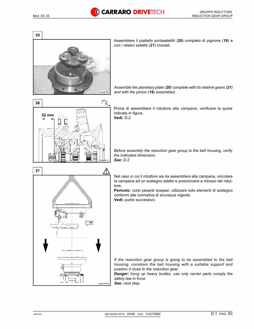
GRUPPO RIDUTTOREMod. EC 35 REDUCTION GEAR GROUP
AB10424 D.1 PAG. 63REVISION DATE: 09/08 DOC. CA270069
35Assemblare il piattello portasatelliti (20) completo di pignone (19) econ i relativi satelliti (21) montati.
Assemble the planetary plate (20) complete with its relative gears (21)and with the pinion (19) assembled.
36Prima di assemblare il riduttore alla campana, verificare la quotaindicata in figura.Vedi: D.2
Before assembly the reduction gear group to the bell housing, verifythe indicated dimension.See: D.2
37Nel caso in cui il riduttore sia da assemblare alla campana, vincolarela campana ad un sostegno adatto e posizionarla a ridosso del ridut-tore.Pericolo: corpi pesanti sospesi, utilizzare solo elementi di sostegnoconformi alla normativa di sicurezza vigente.Vedi: punto successivo.
If the reduction gear group is going to be assembled to the bellhousing, constrain the bell housing with a suitable support andposition it close to the reduction gear.Danger: hung up heavy bodies, use only carrier parts comply thesafety law in force.See: next step.
52 mm

GRUPPO RIDUTTOREMod. EC 35 REDUCTION GEAR GROUP
AB10424 D.1 PAG. 64REVISION DATE: 09/08 DOC. CA270069
38Posizionare i due elementi in modo che l’ingrassatore del riduttore siain asse con l’asola della campana indicata in figura.
Position the two elements in a way that the greaser in the reductiongear results aligned with the buttonhole in the bell housing indicatedin figure.
39Assemblare e serrare alla coppia prevista le viti di fissaggio (10).Vedi: C.7
Assemble and tighten to the requested torque the fixing bolts (10).See: C.7
10

GRUPPO RIDUTTOREMod. EC 35 REDUCTION GEAR GROUP
AB10424 D.1 PAG. 65REVISION DATE: 09/08 DOC. CA270069
D.1.3 Definition of starting thickness value (X) for the adjustment of wheel hub roller bearings preloading
D.1.3 Determinazione spessore iniziale (X) per la registrazione del precarico cuscinetti mozzo ruota
1Questa procedura viene utilizzata per determinare lo spessore inizialedi registrazione precarico cuscinetto (X).Nota: si consiglia di utilizzare spessori di valore iniziale totale pari aX= 1.3 mm .
This procedure must be employed to define the value of the startingthickness (X) for the wheel hub roller bearings preloading adjustment.Note: it’s recommended use a quantity of shims in a way to reach thestarting value X= 1.3 mm.
2Effettuare la registrazione del precarico dei cuscinetti mozzo ruota (6):
• bloccare su morsa o su specifico attrezzo la flangia del mozzoruota (6);
• azzerare l’attrezzatura di registrazione CA716318 con comparato-re su un piano di riscontro, come da figura;
• montare l’attrezzatura sul mozzo ruota (6) fissandolo con una viteTCEI M16x80.
Register wheel hub (6) roller bearings preloading:
• hold firmly on a vice or in a specific tool the flange of the wheel hub(6);
• set to zero the adjustment equipment CA716318 by means of thedial gauge on a surface plate, as shown in figure;
• assemble the group on the wheel hub (6) locking it by means of ascrew TCEI M16x80.
X3
2
6

GRUPPO RIDUTTOREMod. EC 35 REDUCTION GEAR GROUP
AB10424 D.1 PAG. 66REVISION DATE: 09/08 DOC. CA270069
3• precaricare i cuscinetti conici (9) e (13) con una vite M16x80 fino
ad ottenere un precarico misurato (P) di 46.2÷69.4 N, tangente aldiametro della corona dentata, sul quale è avvolta la funicella (vedifigura), applicando una rotazione di circa 15 giri al minuto.
Effettuare la registrazione con i soli componenti indicati in figura.
• preload the tapered bearings (9) and (13) with the screw M16x80up to a 46.2÷69.4 N measured load (P), tangent to the diameter ofthe crown gear, where the cord is wound (see the figure), applyinga rotation of about 15 rpm.
Carry out the operation using only the components shown in figure.
4Rilevare con il comparatore centesimale il valore (X) della quotaindicata in figura.
Read the value (X) from the dial gauge as shown in figure.
5Rimuovere l’attrezzo CA716318 ed il comparatore.Montare la ralla (5) ed un nuovo OR (4).Lubrificare l’OR (4).Vedi: C.6
Disassemble the tool CA716318 and the dial gauge.Install the thrust washer (5) and the new O-Ring (4).Lubricate the O-Ring (4).See: C.6
6Comporre con gli spessori (3) disponibili, indicati in tabella, il valorerilevato (X) all’interno della ralla (2).Procedere come indicato in D.2.1.22.
GAMMA SPESSORI - SHIMS RANGESpessore/Thickness - mm 0.05 0.10 0.30 0.50
Quantità/Quantity --- --- ---
Choose among the available shims (3) a quantity in a way to reach thepreviously measured value (X) and place them in the washers (2).Follow the instructions from step D.2.1.22.
9
13
P
X
5
4
X3
2

GRUPPO FRENOMod. EC 35 BRAKE GROUP
AB10424 D.2 PAG. 67REVISION DATE: 09/08 DOC. CA270069
D.2 Brake group
D.2.1 Disassembly
Some of the following pictures may not show exactlyyour axle, but the indicated operations are correctanyway.
D.2 Gruppo freno
D.2.1 Smontaggio
Alcune figure che seguono potrebbero non mostrareesattamente il vostro assale, ma la procedura descrittaè quella corretta.
1Separare il riduttore dalla campana.Vedi: D.1
Disassemble the reduction gear from the housing.See: D.1
1
2
3
18
11
87
10
5
9
6
1213
14
1516
17
2122
4
1920

GRUPPO FRENOMod. EC 35 BRAKE GROUP
AB10424 D.2 PAG. 68REVISION DATE: 09/08 DOC. CA270069
2Rimuovere il supporto cuscinetto (2) dalla campana (22).Nota: rimuovendo il supporto cuscinetto (2) viene rimosso anche ilsemiasse (3).
Remove the bearing support (2) from the bell housing (22).Note: with the bearing support (2) the half-shaft (3) is also removed.
3Rimuovere l’anello d’arresto (4) e separare il semiasse (3) dalsupporto cuscinetto (2).
Remove the lock ring (4) and separate the half-shaft (3) from thebearing support (2).
4Rimuovere il disco freno (5) e rimuovere l’anello d’arresto (6).
Remove the brake disk (5) and remove the lock ring (6).
5Rimuovere l’anello d’arresto (10).Recuperare i due controdischi (11) e (13) ed i due dischi freno (12) e(14) dall’interno del controdisco (9).Controllare le condizioni di usura dei componenti appena rimossi.Vedi: C.4
Remove the lock ring (10).Collect the two counterdisks (11) and (13) and the two brake disks (12)and (14) from the internal side of the counterdisk (9).Check the wear conditions of the components just removed.See: C.4
223
2
3
2
4
5
6
22
1011
12
14
13

GRUPPO FRENOMod. EC 35 BRAKE GROUP
AB10424 D.2 PAG. 69REVISION DATE: 09/08 DOC. CA270069
6Recuperare il controdisco (7), il disco freno (8), i due controdischi (9)e (15) ed il disco freno (16).Controllare le condizioni di usura dei componenti appena rimossi.Vedi: C.4
Collect the counterdisk (7), the brake disk (8), the two counterdisks (9)and (15) and the brake disk (16).Check the wear conditions of the components just removed.See: C.4
7Rimuovere le 3 viti (17) con le relative rondelle (18) dal pistone (21),quindi recuperare le 3 molle (19).Solo se ne è necessaria la sostituzione, rimuovere le 3 bussole (18).
Remove the 3 bolts (17) with relative washers (18) from the piston(21), then collect the spring (19).Only if it is necessary the replacement, remove the 3 bushes (20).
8Rimuovere il pistone (21) dall’interno della campana (22).
Remove the piston (21) from the inside of the bell housing (22).
7
8
915
16
18
2019
21
17
22
21

GRUPPO FRENOMod. EC 35 BRAKE GROUP
AB10424 D.2 PAG. 70REVISION DATE: 09/08 DOC. CA270069
D.2.2 Assembly
Some of the following pictures may not show exactlyyour axle, but the indicated operations are correctanyway.
D.2.2 Montaggio
Alcune figure che seguono potrebbero non mostrareesattamente il vostro assale, ma la procedura descrittaè quella corretta.
1Pulire con cura il pistone e la sua sede nella campana.
Clean with care the piston and the piston seat into the housing.
2Lubrificare anche la sede interna alla campana.
Lubricate also the piston seat into the housing.
3Assemblare il pistone (21) all’interno della campana (22).Nota: solo se è precedentemente rimosse, assemblare le 3 bussole(20) dei gruppi self-adjust nelle relative sedi nel pistone (21).Vedi: passo successivo.
Assemble the piston (21) inside of the bell housing (22).See: Only if previously removed,insert the 3 bushes (20) of the self-adjust groups into the piston (21).See: next step.
21
22

GRUPPO FRENOMod. EC 35 BRAKE GROUP
AB10424 D.2 PAG. 71REVISION DATE: 09/08 DOC. CA270069
4Applicare il sigillante prescritto sul filetto dellle viti (17).Vedi: C.7Assemblare le 3 molle (19) e le 3 viti (17) con le relative rondelle (18).Serrare le viti (17) alla coppia prevista.Vedi: C.7
Apply the prescribed sealant on the bolts (17) thread.See: C.7Assemble the 3 springs (19) and the 3 bolts (17) with relative washers(18).Tighten the bolts (17) to the requested torque.See: C.7
5Assemblare nell’ordine i seguenti elementi del gruppo freno: il discofreno (16), i controdischi (15) e (9), il disco freno (8) ed il controdisco(7).Nota: il disco (16) deve essere montato con il materiale d’attrito rivoltoverso il controdisco (15), mentre il disco (8) deve essere montato conil materiale d’attrito rivolto verso il controdisco (7).
Assemble in the following order these brake group elements: thebrake disk (16), the counterdisks (15) and (9), the brake disk (8) andthe counterdisk (7).Note: the disk (16) must be assembled with the friction material turnedtoward the counterdisk (15), while the disk (8) must be assembled withthe friction material turned toward the counterdisk (7)
6Inserire all’interno del controdisco (9) il disco freno (14), il controdisco(13), il disco freno (12) ed il controdisco (11).Vincolare il tutto con l’anello d’arresto (10).Nota: il disco (14) deve essere montato con il materiale d’attrito rivoltoverso il controdisco (13), mentre il disco (12) deve essere montato conil materiale d’attrito rivolto verso il controdisco (11).
Assemble to the internal side of the counterdisk (9) the brake disk (14),the counterdisk (13), the brake disk (12) and the counterdisk (11).Constrain the disks with the lock ring (10).Note: the disk (14) must be assembled with the friction material turnedtoward the counterdisk (13), while the disk (12) must be assembledwith the friction material turned toward the counterdisk (11)
7Assemblare l’anello d’arresto (6) ed il disco freno (5).
Assemble the lock ring (6) and the brake disk (5).
18
2019
2117
7
8
915
16
1011
12
14
13
5
6
22

GRUPPO FRENOMod. EC 35 BRAKE GROUP
AB10424 D.2 PAG. 72REVISION DATE: 09/08 DOC. CA270069
8Assemblare il semiasse (3) al supporto cuscinetto (2) utilizzandol’attrezzo speciale CA716319.Vedi: punto successivo.Vincolare il semiasse (3) al supporto cuscinetto (2) mediante l’anellod’arresto (4)
Assemble the half-shaft (3) to the bearing support (2) by using thespecial tool CA716319.See: next step.Constrain the half-shaft (3) to the bearing support (2) with the lock ring(4).
9Schema di montaggio del semiasse (3): utilizzare il tamponeCA716319 (t1).
Half-shaft (3) assembly scheme: use the special tool CA716319 (t1).
10Assemblare il gruppo supporto cuscinetto/semiasse alla campana(22), inserendo il semiasse (3) all’interno della scatola differenziale.
Assemble the bearing support/half-shaft group to the bell housing(22), by inserting the half-shaft (3) into the differential box.
11Verificare il corretto assemblaggio del gruppo cuscinetto/semiasse: ilvalore della quota deve essere quello indicato in figura.
Verify the correct support/half-shaft group assembly: the dimensionmust have the value indicated in figure.
3
2
4
3t1
2
223
2
52 mm

GRUPPO FRENOMod. EC 35 BRAKE GROUP
AB10424 D.2 PAG. 73REVISION DATE: 09/08 DOC. CA270069
12Assemblare un nuovo OR (1) nella relativa sede dela campana (22).Lubrificare l’OR (1) con il grasso prescritto.Vedi: C.6
Assemble a new O-Ring (1) to the relative seat in the bell housing (22).Lubrify the O-Ring (1) with the prescribed grease.See: C.6
13Dopo aver assemblato il gruppo freno è possibile procedere con ilmontaggio della campana sul riduttore.Vedi: D.1.2
After the brake group assembly operations it is posible to assemblethe bell housing on the reduction gear.See: D.1.2
22
1

GRUPPO CAMPANAMod. EC 35 BELL HOUSING GROUP
AB10424 D.3 PAG. 74REVISION DATE: 09/08 DOC. CA270069
D.3 Bell housing group
D.3.1 Disassembly
Some of the following pictures may not show exactlyyour axle, but the indicated operations are correctanyway.
D.3 Gruppo campana
D.3.1 Smontaggio
Alcune figure che seguono potrebbero non mostrareesattamente il vostro assale, ma la procedura descrittaè quella corretta.
1Rimuovere il gruppo freno dalla campana.Vedi: D.2.1
Remove the brake group from the bell housing.See: D.2.1
6
5 4
3
2
1

GRUPPO CAMPANAMod. EC 35 BELL HOUSING GROUP
AB10424 D.3 PAG. 75REVISION DATE: 09/08 DOC. CA270069
2Posizionare la campana sul banco di lavoro e rimuovere l’anellod’arresto (2) utilizzando una pinza adatta.
Position the bell housing in a workbench and remove the lock ring (2)with a suitable pliers.
3Estrarre dalla campana (5) il differenziale completo di cuscinetto.Rimuovere l’anello d’arresto (4) e separare il cuscinetto (3) dallascatola differenziale (1).
Extract from the bell housing (5) the differential complete with thebearing.Remove the lock ring (4) and separate the bearing (3) from the differ-ential box (1).
4Rimuovere l’anello di tenuta (6) dalla campana (5).Nota: operazione distruttiva per la tenuta (6); la tenuta dovrà esseresostituita.
Remove the seal ring (6) from the bell housing (5).Note: destructive operation for the seal ring (6); the sealring must bereplaced.
2
43
2
5
5
6

GRUPPO CAMPANAMod. EC 35 BELL HOUSING GROUP
AB10424 D.3 PAG. 76REVISION DATE: 09/08 DOC. CA270069
D.3.2 Assembly
Some of the following pictures may not show exactlyyour axle, but the indicated operations are correctanyway.
D.3.2 Montaggio
Alcune figure che seguono potrebbero non mostrareesattamente il vostro assale, ma la procedura descrittaè quella corretta.
1Assemblare il cuscinetto (3) alla scatola differenziale (1) utilizzandol’attrezzo speciale CA716309 ed un martello.Vedi: punto successivo.Vincolare il cuscinetto (3) alla scatola differenziale (1) tramite l’anellod’arresto (4).
Assemble the bearing (3) to the differential box (1) by using the specialtool CA719309 and a hammer.See: next step.Constrain the bearing (3) to the differential box (1) with the lock ring(4).
2Schema di montaggio del cuscinetto (3): utilizzare l’attrezzo specialeCA716309 (t1).
Bearing (3) assembly scheme: use the special tool CA719309 (t1).
3Posizionare la campana sul banco di lavoro.Assemblare il differenziale completo di cuscinetto alla campana (5)utilizzando l’attrezzo speciale CA716328 ed un martello.Vedi: punto successivo.Assemblare l’anello d’arresto (2) utilizzando una pinza adatta.
Position the bell housing in a workbench.Assemble the differential complete with the bearing to the bellhousing (5) by using the special tool CA716328 and a hammerSee: next step.Assemble the lock ring (2) with suitable pliers.
3
2
4
3
t1
1
2
5

GRUPPO CAMPANAMod. EC 35 BELL HOUSING GROUP
AB10424 D.3 PAG. 77REVISION DATE: 09/08 DOC. CA270069
4Schema di montaggio del differenziale (1): utilizzare l’attrezzospeciale CA716328 (t2).
Differential (1) assembly scheme: use the special tool CA716328 (t2).
5Lubrificare un nuovo anello di tenuta (6).Vedi: C.6Assemblare l’anello di tenuta (6) alla campana (5) utilizzandol’attrezzo speciale CA716327 ed un martello.Vedi: punto successivo.Assemblare alla campana (5) il gruppo freno.Vedi: D.2.2
Lubricate a new seal ring (6).See: C.6Assemble the seal ring (6) to the bell housing (5) by using the specialtool CA716327 and a hammer.Assemble the brake group to the bell housing (5).See: D.2.2
6Schema di montaggio dell’anello di tenuta (6): utilizzare l’attrezzospeciale CA716327 (t3).Nota: rispettare il verso di montaggio indicato in figura.
Seal ring (6) assembly scheme: use the special tool CA716327 (t3).Note: respect the assembly direction shown in figure.
1
t2
5
6
6t3

GRUPPO DIFFERENZIALEMod. EC 35 DIFFERENTIAL GROUP
AB10424 D.4 PAG. 78REVISION DATE: 09/08 DOC. CA270069
D.4 Differential group
D.4.1 Disassembly
Some of the following pictures may not show exactlyyour axle, but the indicated operations are correctanyway.
D.4 Gruppo differenziale
D.4.1 Smontaggio
Alcune figure che seguono potrebbero non mostrareesattamente il vostro assale, ma la procedura descrittaè quella corretta.
1Rimuovere la scatola differenziale dalla campana.Vedi: D.3.1
Remove the differential housing from the bell housing.See: D.3.1
2
12
11
8
7
9
10
6
5
4
31

GRUPPO DIFFERENZIALEMod. EC 35 DIFFERENTIAL GROUP
AB10424 D.4 PAG. 79REVISION DATE: 09/08 DOC. CA270069
2Posizionare la scatola differenziale (12) su un banco di lavoro.Estrarre la spina d’arresto (6) con un cacciaspine ed un martello.
Place the differential housing (12) on a suitable workbench.Extract the fastening pin (6) with a drift and a hammer.
3Estrarre il perno (5) e rimuovere tutti i componenti interni alla scatoladifferenziale: i quattro satelliti e le quattro ralle.Verificare lo stato di usura dei componenti.
Extract the pin (5) and remove all the parts in the differential housing:the four planetary gears and the four thrust washers.Check the wear conditions of all parts.
4Solo se le condizioni di usura lo richiedono, rimuovere la bussola (11)dalla scatola differenziale (12).
Only if the wear conditions require it, remove the bushing (11) fromthe differential box (12).
6
12
11
12

GRUPPO DIFFERENZIALEMod. EC 35 DIFFERENTIAL GROUP
AB10424 D.4 PAG. 80REVISION DATE: 09/08 DOC. CA270069
D.4.2 Assembly
Some of the following pictures may not show exactlyyour axle, but the indicated operations are correctanyway.
D.4.2 Montaggio
Alcune figure che seguono potrebbero non mostrareesattamente il vostro assale, ma la procedura descrittaè quella corretta.
1Solo se precedentemente rimossa, assemblare una nuova bussola(11) alla scatola differenziale (12) utilizzando l’attrezzo specialeCA716320 ed un martello.Vedi: punto successivo.
Only if previously removed, assemble a new bushing (11) to the differ-ential box (12) by using the special tool CA716320 and a hammer.See: next step.
2Schema di montaggio della bussola (11): utilizzare l’attrezzo specialeCA716320 (t1).
Bushing (11) assembly scheme: use the special tool CA716320 (t1).
3Assemblare le ralle (1) e (8) nella scatola differenziale (12).
Assemble the trust washers (1) and (8) in the differential housing (12).
11
12
11
t1
8 1

GRUPPO DIFFERENZIALEMod. EC 35 DIFFERENTIAL GROUP
AB10424 D.4 PAG. 81REVISION DATE: 09/08 DOC. CA270069
4Assemblare il perno (5) e la ralla (10) nella scatola differenziale (12).
Assemble the pin (5) and the trust washer (10) in the differentialhousing (12).
5Assemblare l’ingranaggio (9) quindi l’ingranaggio (4) e la ralla (3) nellascatola differenziale (12).Vincolare le parti assemblate al perno (5).
Assemble the gear (9) then assemble the gear (4) and the trustwasher (3) in the differential housing (12).Fit all the assembled parts with the pin (5).
6Assemblare l’ingranaggio (7) nella scatola differenziale (12).Ruotare l’ingranaggio (7) per posizionarlo in basso.
Assemble the gear (7) in the differential housing (12).Rotate the gears (7) to place it to the bottom.
7Assemblare l’ingranaggio (2) contrapposto all’ingranaggio (7) nellascatola differenziale (12).Ruotare gli ingranaggi (2) e (7) per posizionarli in asse.Vedi: punto successivo
Assemble the gear (2) opposite to gear (7) in the differential housing(12).Rotate the gears (2) and (7) to place them on the axis.See: next step
5 10
5 9
7
2

GRUPPO DIFFERENZIALEMod. EC 35 DIFFERENTIAL GROUP
AB10424 D.4 PAG. 82REVISION DATE: 09/08 DOC. CA270069
8Nota: per verificare il corretto allineamento degli ingranaggi (2) e (7)si consiglia di inserire nella scatola differenziale preassemblata (12) ilsemiasse destro (s); l’allineamento è corretto se il semiasse siinserisce sia dal lato destro che dal lato sinistro.
Note: to check the correct alignment of the gears (2) and (7) insert intothe assembled differential housing (12) the right half-shaft (s); thealignment is correct if the half-shaft can be assembled on both side ofthe housing.
9Montare la spina (6) nella scatola differenziale (12) arrestando il perno(5).
Assemble the pin (6) in the differential housing (12) to lock the pin (5).
10Assemblare la scatola differenziale completa alla campana.Vedi: D.3.2
Assemble the complete differential box to the bell housing.See: D.3.2
s
5
6

GRUPPO COMANDO FRENOMod. EC 35 BRAKE CONTROL GROUP
AB10424 D.5 PAG. 83REVISION DATE: 09/08 DOC. CA270069
D.5 Brake control group
D.5.1 Disassembly
Some of the following pictures may not show exactlyyour axle, but the indicated operations are correctanyway.
D.5 Gruppo comando freno
D.5.1 Smontaggio
Alcune figure che seguono potrebbero non mostrareesattamente il vostro assale, ma la procedura descrittaè quella corretta.
1Posizionare la campana destra orizzontalmente, su di una superficiepiana.Sganciare la molla (5) con un cacciavite.
Place the bell housing horizontal, on a flat surface.Release the spring (5) with a screwdriver.
4
2
5
8
9
7
10
3
6
1
5

GRUPPO COMANDO FRENOMod. EC 35 BRAKE CONTROL GROUP
AB10424 D.5 PAG. 84REVISION DATE: 09/08 DOC. CA270069
2Solo se ne è necessaria la sostituzione, svitare e rimuovere la vite diregolazione (3) ed il relativo dado (2).
Only if it is required the replacement, unscrew and remove theadjusting screw (3) and its relative nut (2).
3Attenzione: praticare dei segni di riferimento sulla testa del perno-forcella (10) e sulla leva (4) di comando freno in modo da poter deter-minare la posizione relativa dei due elementi in fase di montaggio.Rimuovere l’anello d’arresto (1) dal perno-forcella (10).Nota: se necessario estrarre il perno-forcella (10) con una vite comein figura.
Warning: make reference signs on the fork-pin head (10) and on thebrake control lever (2) in order to know the related position in theassembly operation.Remove the lock ring (1) from the fork-pin (10).Note: if necessary extract the fork-pin head (10) with a screw as infigure.
4Rimuovere la leva comando freno a mano (4) e la relativa molla (5).Pericolo: la molla potrebbe essere proiettata con forza contro l’opera-tore, trattenere la molla mentre si sfila la leva.
Remove the control service brake lever (2) and the related spring (5).Danger: the spring can be ejected with force against the operator,keep the spring while extract the lever.
5Rimuovere le viti di fissaggio (6) della bussola (8).
Remove the fastening screws (6) of the bush (8).
2
3
1
10
2
5
6

GRUPPO COMANDO FRENOMod. EC 35 BRAKE CONTROL GROUP
AB10424 D.5 PAG. 85REVISION DATE: 09/08 DOC. CA270069
6Separare il gruppo riduttore dalla campana.Vedi: D.1.1
Disassemble the reduction gear group from the bell housing.See: D.1.1
7Disassemblare il gruppo freno.Vedi: D.2.1
Disassemble the brake group.See: D.2.1
8Rimuovere la bussola guida (8).
Remove the guide bush (8).
9Rimuovere gli OR (7) e (9) dalla bussola guida (8).Nota: operazione distruttiva per gli OR (7) e (9); gli OR dovrannoessere sostituiti.
Remove the O-Rings (7) and (9) from the guide bush (8).Note: destructive operation for the O-Rings (7) and (9); the O-Ringmust be replaced.
8
7 9
8

GRUPPO COMANDO FRENOMod. EC 35 BRAKE CONTROL GROUP
AB10424 D.5 PAG. 86REVISION DATE: 09/08 DOC. CA270069
D.5.2 Assembly
Some of the following pictures may not show exactlyyour axle, but the indicated operations are correctanyway.
D.5.2 Montaggio
Alcune figure che seguono potrebbero non mostrareesattamente il vostro assale, ma la procedura descrittaè quella corretta.
10Estrarre dalla campana il perno-forcella (10) di azionamento freno amano.
Extract from the housing the control service brake fork-pin (10).
1Applicare il grasso prescritto alla superficie del perno-forcella (10).Vedi: C.6Inserire nella campana il perno-forcella (10).Attenzione: rispettare il corretto senso di montaggio, gli attuatoridevono essere verso il pistone.
Apply the prescribed grease on the fork-pin (10) surface.See: C.6Insert in the housing the fork-pin (10).Warning: respect the correct assembly position.
2Posizionare il perno-forcella (10) sul lato indicato.
Place the fork-pin (10) on the indicated side.
10
10

GRUPPO COMANDO FRENOMod. EC 35 BRAKE CONTROL GROUP
AB10424 D.5 PAG. 87REVISION DATE: 09/08 DOC. CA270069
3Assemblare due nuovi OR (7) (9) ben lubrificati nelle rispettive sedisulla bussola (8).Vedi: C.6
Assemble two new well lubricated O-Rings (7) and (9) in the relativeseats on the guide bush (8).See: C.6
4Applicare il grasso prescritto sulla superficie della bussola (8).Vedi: C.6Assemblare la bussola guida (8).
Apply the prescribed grease on the guide bush (8) surface.See: C.6Assemble the guide bush (8).
5Montare e serrare le viti di fissaggio (6) della bussola (8) con unachiave dinamometrica alla coppia prevista.Vedi: C.7
Assemble and tighten the fastening screws (6) of the bush (8) with adynamometric wrench to the prescribed torque.See: C.7
6Assemblare il gruppo freno.Vedi: D.2.2
Assemble the brake group.See: D.2.2
79 8
8
6

GRUPPO COMANDO FRENOMod. EC 35 BRAKE CONTROL GROUP
AB10424 D.5 PAG. 88REVISION DATE: 09/08 DOC. CA270069
7Assemblare la campana sul riduttore.Vedi: D.1.2
Assemble the housing on the reduction gear.See: D.1.2
8Assemblare la molla (5).
Assemble the spring (5).
9Assemblare la vite (3) ed il dado (2) alla campana.
Assemble the bolt (3) and nut (2) to the bell housing.
10Assemblare la leva comando freno a mano (4).Nota: rispettare i segni di riferimento fatti allo smontaggio fra leva (4)e perno-forcella (10).
Assemble the control service brake lever (4).Note: align the reference mark made in the disassembly on the fork-pin (10) and the control service brake lever (4).
5
3
2
4

GRUPPO COMANDO FRENOMod. EC 35 BRAKE CONTROL GROUP
AB10424 D.5 PAG. 89REVISION DATE: 09/08 DOC. CA270069
11Comprimere la molla (5) con la leva (4) per consentire il montaggiodell’anello d’arresto (1) all’estremità del perno-forcella (10).Nota: si consiglia di utilizzare un attrezzo adatto.
Compress the spring (5) by forcing the lever (4) to allow the assemblyof the lock ring (1) on the fork-pin (10) end.Note: it is advisable to use a suitable tool.
12Assemblare l’anello d’arresto (1) al perno-forcella (10).
Assemble the lock ring (1) to the fork-pin (10).
13Agganciare la molla (5) alla leva di comando (4) con l’aiuto di uncacciavite.
Connect the spring (5) to the control brake lever (4) by means of ascrewdriver.
14Verificare che la leva comando freno a mano (4) non sia bloccata.
Check that the control service brake lever (4) are not locked.
4
1

GRUPPO COMANDO FRENOMod. EC 35 BRAKE CONTROL GROUP
AB10424 D.5 PAG. 90REVISION DATE: 09/08 DOC. CA270069
15Per la registrazione della leva di comando (4), applicare una forza Fdi 1000 N ed interporre uno spessore (s) di 7 mm tra leva e testa dellavite (3) come indicato in figura.
For the control brake lever (4) registration, apply a 1000 N force F andput a 7 mm spacer (s) between the lever and screw (3) head as shownin figure.
16Regolare la vite (3) fino a portarla a contatto con lo spessore (s) ebloccarla con il controdado (2).
Adjust the screw (3) until bring it in contact with the spacer (s) and lockthe screw with the nut (2).
17Una volta rimosso lo spessore, la dimensione indicata in figura deverientrare nel campo di misura previsto.
Once removed the spacer, the indicated dimension must be into thespecified measurement range.
F7 mm
s
4
s 2
3
4
108.5 ± 9 mm
RICERCA GUASTIMod. EC 35 TROUBLESHOOTING
AB10424 E PAG. 91REVISION DATE: 09/08 DOC. CA270069
E TROUBLESHOOTING
E RICERCA GUASTI

Mod. EC 35
AB10424 PAG. 92REVISION DATE: 09/08 DOC. CA270069
Solving action
1 Incorrect installation / defective axleCorrect installation or repair or replace the differential incase it does not survive any one of the test phases.
2 Overloading / incorrect weight distributionRemove excessive weight and redistribute load,following instructions related to the vehicle.
Azione consigliata
1 Installazione scorretta / assale difettosoCorreggere l'installazione oppure, se il differenziale nonsupera una delle fasi di prova, ripararlo o sostituirlo.
2 Sovraccarico / distribuzione scorretta del pesoTogliere il peso in eccesso e ridistribuire il carico, rispet-tando le istruzioni relative al veicolo.
PROBLEMA POSSIBILI CAUSE
1 2 3 4 5 6 7 8 9 10 11
- Vibrazioni delle ruote; resistenza del pneumatico anteriore; rottura del/i semiasse/i.
- Difficoltà nello sterzare; il veicolo tende ad andare dritto mentre è in curva.
- Non vi è azione del differenziale; inceppamento in curva.
- Rumore eccessivo nella trasmissione.
- Usura eccessiva del pneumatico.
- Rumore di attrito.
- In marcia avanti si avvertono vibrazioni, rumore intermittente.
PROBLEMS POSSIBLE CAUSES
1 2 3 4 5 6 7 8 9 10 11
- Wheel vibration; front tyre resistance; half-shaft breakage.
- Steering is difficult; vehicle goes straight while its turning.
- No differential action; jamming while steering.
- No differential action; jamming while steering.
- Uneven wear of tyre.
- Friction noise.
- Vibration during forward drive, intermittent noise.

Mod. EC 35
AB10424 PAG. 93REVISION DATE: 09/08 DOC. CA270069
3 Different rotation radius of the tyresIf one tyre has a smaller radius, it will cause partialwheel slipping when force is applied. The other tyre withbigger radius will have to support all the work. Replacethe tyre or adjust pressure to have same radius on bothtyre.
4 Broken half-shaftIt is not advisable to operate the vehicle with a brokenhalf-shaft. It is acceptable to move the vehicle (engineoff unloaded) a few meters away only.
5 Bent half-shaftReplace half-shaft.
6 Blocked differentialAbnormal functioning of the differential or breakage/blockage of command device. Verify assembly and allcomponents.Vehicles with wide steering angle may proceed withkicks, have steering difficulty or cause pneumaticwearing at sharp turns. Reduce the steering angle tominimum and decelerate when the vehicle begins tokick.
7 Incorrect wheel adjustmentVerify group integrity and wheel side bearings.Adjusting according.
8 Spoiled or worn out axle partsCheck the condition of ring gear, pinion gear, bearingsetc. Replace when ever necessary.
9 Contamination in the axle box or incorrectassembly of parts
Look for foreign particles. Check assembly of thevarious parts of the axle.
10 Incorrect adjustment of bevel gear set: Parts ofthe transmission worn out.
(transmission gears, U joints, etc.)Replace or adjust as required.
11 Incorrect use of the productSee the vehicle producer‘s instructions once again.
3 Raggio di rotazione degli pneumatici diversiUn pneumatico con raggio più piccolo provoca unparziale slittamento della ruota quando si applicaenergia. L'altro pneumatico con raggio maggiore dovràsopportare tutto il lavoro. Sostituire il pneumatico oregolare la pressione di entrambi sino a che il raggio dirotazione sia uguale.
4 Semiasse rottoE' sconsigliato usare un veicolo con un solo semiasse.E' possibile tuttavia spostare il veicolo a vuoto con ildifferenziale bloccato per pochi metri.
5 Semiasse piegatoSostituire i semiassi.
6 Differenziale bloccatoFunzionamento anomalo del differenziale e/o rotturadel dispositivo di comando del bloccaggio di comando.Verificare l'installazione, eventualmente smontare everificare i componenti.I veicoli impostati per angoli di sterzata ampi, possonoprocedere a scatti, avere difficoltà di sterzo e provocareun consumo del pneumatico nelle curve strette.Ridurre l'angolo di sterzata minimo e decelerarequando il motore inizia a procedere a scatti.
7 Allineamento scorretto della ruotaVerificare l'integrità della struttura, e cuscinetti latoruota.
8 Parti dell'assale consumate o difettoseControl lare le condizioni della corona dentata,dell'ingranaggio del pignone, dei cuscinetti, delle guar-nizioni, ecc. Sostituire dove necessario.
9 Corpi estranei nella scatola dell'assale omontaggio scorretto di alcune sue parti
Controllare se vi sono corpi estranei. Controllare ilmontaggio delle parti dell'assale.
10 Regolazioni della coppia conica scorrette: partidi trasmissione consumate
(ingranaggi di trasmissione, giunti, ecc.). Sostituire oregolare secondo necessità.
11 Uso scorretto del prodottoRivedere le istruzioni rilasciate dal produttore delveicolo.

CONTROLLO ED ESAME DEI GUASTIMod. EC 35
AB10424 E.1 PAG. 94REVISION DATE: 09/08 DOC. CA270069
E.1 Controllo ed esame dei guasti
Questo capitolo offre una guida descrittiva ed esplicativa di problemi che si possono comunemente riscontrare sugliassali o di avarie che si possono verificare. La guida suggerisce anche le corrette procedure di riparazione.
Problema Causa Azione consigliata
Rottura verso l'estremità esterna del dente corona dentata
1. Carico dell'ingranaggio eccessivo rispetto a quello previsto2. Regolazione ingranaggio scorretto (gioco eccessivo)3. Dado del pignone allentato.
Sostituire la coppia conica.Seguire attentamente le operazioni raccomandate di regolazione del gioco della corona dentata e del pignone e per la rilevazione dell’impronta del dente.
Rottura verso l'estremità interna del dente corona dentata
1. Urto da carico2. Regolazione ingranaggio scorretto (gioco insufficiente)3. Dado del pignone allentato
Sostituire la coppia conica.Seguire attentamente le operazioni raccomandate di regolazione del gioco della corona dentata e del pignone e per la rilevazione dell’impronta del dente
Denti del pignone e della corona dentata erosi o rigati
1. Lubrificazione insufficiente2. Lubrificante sporco3. Lubrificante errato o con additivi impoveriti4. Cuscinetti del pignone consumati che provocano un gioco assiale del pignone e un contatto tra pignone e corona scorretto.
Sostituire la coppia conica.Sostituire i cuscinetti del pignone facendo attenzione a sistemare correttamente la corona, il pignone e i precarichi dei cuscinetti.Usare il lubrificante corretto, riempire fino al giusto livello e sostituirlo agli intervalli raccomandati.
Denti della corona e del pignone surriscaldati. Guardare se i denti dell'ingranaggio hanno perso la colo-razione
1. Funzionamento prolungato a temperatura eccessiva.2. Lubrificante scorretto3. Livello dell'olio basso4. Lubrificante sporco.
Sostituire la coppia conica.Usare il lubrificante corretto, riempire fino al giusto livello e sostituirlo agli intervalli raccomandati.
Denti del pignone di comando butterati
1. Uso estremamente intenso2. Lubrificazione insufficiente
Sostituire la coppia conica.Usare il lubrificante corretto, riempire fino al giusto livello e sostituirlo agli intervalli raccomandati.
Corpo trave dell'assale piegato 1. Sovraccarico del veicolo2. Veicolo incidentato3. Urto da carico
Sostituire il corpo trave dell'assale
Cuscinetti consumati o butterati 1. Lubrificazione insufficiente2. Lubrificante sporco3. Uso estremamente intenso4. Consumo normale5. Dado del pignone allentato.
Sostituire i cuscinetti.Usare il lubrificante corretto, riempire fino al giusto livello e sostituirlo agli intervalli raccomandati.
Le guarnizioni perdono olio 1. Funzionamento prolungato con temperatura dell'olio eccessiva.2. Guarnizione dell'olio montata male3. Bordo della guarnizione tagliata o intaccata4. Lubrificante sporco
Sostituire la guarnizione e la super-ficie di accoppiamento se danneg-giata.Usare il lubrificante corretto, riempire fino al giusto livello e sostituirlo agli intervalli raccomandati.

CONTROLLO ED ESAME DEI GUASTIMod. EC 35
AB10424 E.1 PAG. 95REVISION DATE: 09/08 DOC. CA270069
Usura eccessiva della scanalatura della flangia di entrata.
1. Uso intenso2. Dado del pignone allentato3. Gioco assiale del pignone
Sostituire la flangiaControllare che la scanalatura del pignone non sia eccessivamente consumataSostituire la coppia conica, se neces-sario.
Rottura per fatica del dente dell'ingranaggio del pignone. Guardare se la linea di frattura ad onda è ben delineata (linea di arresto).
1. Uso intenso2. Sovraccarico continuo
Sostituire la coppia conica.
Rottura denti pignone e corona Carico d'urto dei componenti del diffe-renziale
Controllare e/o sostituire altri compo-nenti differenziale.
Scanalature dell'ingranaggio plane-tario consumate (gioco eccessivo)
Uso intenso Sostituire il gruppo ingranaggi diffe-renziale. Sostituire il semiasse, se necessario.
Superfici della ralla di rasamento consumate o graffiate
1. Lubrificazione insufficiente2. Lubrificazione scorretta3. Lubrificante sporco
Sostituire tutte le ralle graffiate e quelle con uno spessore di 0,1 mm inferiore a quello delle ralle nuove.Usare il lubrificante corretto, riempire fino al giusto livello e sostituirlo agli intervalli raccomandati.
Diametro interno del cuscinetto a rulli conici del pignone consumato
1. Uso intenso2. Gioco assiale del pignone eccessivo3. Lubrificazione inadeguata4. Lubrificante sporco
Sostituire il cuscinettoControllare il gioco assiale del pignoneUsare il lubrificante corretto, riempire fino al giusto livello e sostituirlo agli intervalli raccomandati.
Semiasse ritorto o rotto Funzionamento intenso del veicolo, sovraccarico
Sostituire il semiasse
Semiasse spezzato presso la flangia ruota
1. Supporto della ruota allentato2. Corpo trave piegato
Sostituire il semiasseControllare la distorsione del corpo trave. Accertarsi che il sostegno della ruota non sia consumato o mal regolato.
Problema Causa Azione consigliata

CONTROLLO ED ESAME DEI GUASTIMod. EC 35 TROUBLESHOOTING
AB10424 E.1 PAG. 96REVISION DATE: 09/08 DOC. CA270069
E.1 Troubleshooting
This chapter is a descriptive and explanatory guide to common axle problems. This guide suggests the repair correctprocedures to be followed.
Problem Cause Action
Ring gear tooth broken at the outer side
1. Excessive gear load compared to the one foreseen2. Incorrect gear adjustment (exces-sive backlash)3. Pinion nut loose
Replace bevel gear setFollow carefully the recommended operations for the adjustment of bevel gear set backlash
Ring gear tooth broken side 1. Load bump2. Incorrect gear adjustment (insuffi-cient backlash)3. Pinion nut loose
Replace bevel gear setFollow carefully the recommended operations for the adjustment of bevel gear set backlash.
Pinion or ring gear teeth or worn 1. Insufficient lubrication2. Contaminated oil3. Incorrect lubrication or depleted additives4. Worn out pinion bearings that cause an incorrect pinion axle backlash and wrong contact between pinion and ring.
Replace bevel gear set.Follow carefully the recommended operations for the adjustment of bevel gear set backlash.Use correct lubricants, fill up to the right levels and replace according to the recommended program.
Overheated ring and pinion teeth. See if gear teeth have faded
1. Prolong ed functioning at high temperatures2. Incorrect lubrication3. Low oil level4. Contaminated oil
Replace bevel gear set.Use proper lubrication, fill up to right level and replace at recommended program.
Pinion teeth pitting 1. Excessive use2. Insufficient lubrication
Replace bevel gear set.Use correct lubrication, fill up to the right level and substitute at recom-mended intervals
Axle beam body bent 1. Vehicle over loaded2. Vehicle's accident3. Load bump
Replace axle beam body
Worn out or pitted bearings 1. Insufficient lubrication2. Contaminated oil3. Excessive use4. Normal wear out5. Pinion nut loose
Replace bearings.Use correct lubrication fill up, to the right level and replace at recom-mended intervals
Oil leakage form gaskets and seals 1. Prolonged functioning at high temperature of the oil2. Oil gasket assembled incorrectly3. Seal lip damaged4. Contaminated oil
Replace the gasket or seal and matching surface if damaged.Use correct lubrication and replace at recommended intervals.
Excessive wearing out of input flange spline
1. Exhaustive use2. Pinion nut loose3. Pinion axle backlash
Replace the flange.Check that the pinion spline is not excessively worn out.Replace bevel gear set if required.
Fatigue failure of pinion teethSee if the fracture line is well defined(wave lines, beach lines)
1. Exhaustive use2. Continuos overload
Replace bevel gear set

CONTROLLO ED ESAME DEI GUASTIMod. EC 35 TROUBLESHOOTING
AB10424 E.1 PAG. 97REVISION DATE: 09/08 DOC. CA270069
Pinion and ring teeth breakage 1. Crash load of differential compo-nents
Check and/or replace other differential components.
Side gear spline worn out(Excessive backlash)
Excessive use Replace differential gear group.Replace half-shaft if required
Thrust washer surface worn out or scratched.
1. Insufficient lubrication2. Incorrect lubrication3. Contaminated oil
Use correct lubrication and fill up to right level.Replace at intervals recommended.Replace all scratched washers and those with 0,1mm thickness lower than the new ones.
Inner diameter of tapered roller bearing worn out.
1. Excessive use2. Excessive pinion axial backlash3. Insufficient lubrication4. Contaminated oil
Replace bearing.Check pinion axial backlash.Use proper lubrication, fill up to right level and replace at recommended intervals.
Bent or broken half-shaft Vehicle intensively operated or over-loaded
Replace
Half-shaft broken at wheel side 1. Wheel support loose2. Beam body bent
Replace Check that wheel support is not worn out or wrongly adjusted.
Problem Cause Action

DIAGNOSI PER PROBLEMI ALL'ASSALEMod. EC 35 TROUBLESHOOTING
AB10424 E.2 PAG. 98REVISION DATE: 09/08 DOC. CA270069
E.2 Diagnosi per problemi all'assale
Problema Causa Azione consigliata
Rumore durante la guida 1. Gioco tra corona dentata e pignone eccessivo2. Pignone e corona dentata consumati3. Cuscinetti del pignone consumati4. Cuscinetti del pignone allentati5. Gioco assiale del pignone eccessivo6. Cuscinetti del differenziale consumati7. Cuscinetti del differenziale allentati8. Eccessiva scentratura della corona dentata9. Livello lubrificante basso10. Lubrificante di grado povero od errato11. Semiasse piegato
1. Regolare
2. Sostituire
3. Sostituire4. Regolare5. Regolare
6. Sostituire
7. Regolare8. Sostituire
9. Rabboccare10. Sostituire
11. Sostituire
Rumore durante l’andatura in folle 1. I rumori provenienti dall'assale con il veicolo in movimento di solito si sentono durante l’andatura in folle anche se non molto forti2. Errato gioco tra pignone e corona (il rumore che si sente decelerando sparisce all’aumentare della velocità).3. Usura scanalatura pignone o flangia entrata
1. Regolare o sostituire (vedere sopra)
2. Regolare
3. Sostituire
Rumore intermittente 1. Corona dentata danneggiata2. Bulloni della scatola del differen-ziale allentati
1. Sostituire coppia conica2. Serrare a coppia
Rumore costante 1. Danni sui denti della corona dentata o del pignone2. Cuscinetti usurati3. Scanalature del pignone consumate4. Semiasse piegato
1. Sostituire coppia conica
2. Sostituire3. Sostituire
4. Sostituire
Rumore in curva 1. Satelliti planetari differenziale consumati2. Scatola differenziale e/o perni del differenziale consumati3. Ralle di rasamento del differenziale consumate4. Scanalature del semiasse consumate
1. Sostituire
2. Sostituire
3. Sostituire
4. Sostituire

DIAGNOSI PER PROBLEMI ALL'ASSALEMod. EC 35 AXLE PROBLEM AND DIAGNOSIS
AB10424 E.2 PAG. 99REVISION DATE: 09/08 DOC. CA270069
E.2 Axle problem and diagnosis
Problem Cause Action
Noise while driving 1. Excessive backlash between pinion and ring gear2. Worn out pinion and gear ring3. Worn out pinion bearings4. Pinion bearings loose5. Excessive axial pinion backlash6. Worn out differential bearings7. Differential bearings loose8. Ring gear out of roundness9. Low lubricant level 10. Poor or wrong lubricant11. Bent half-shaft
1. Adjust
2. Replace3. Replace4. Adjust5. Adjust6. Replace7. Adjust8. Replace9. Oil level10. Replace11. Replace
Noise while driving in neutral 1. Noise coming from axle are usually heard when vehicle moves in neutral gear but are not loud.2. Incorrect backlash between pinion and ring (sound heard while deceler-ating disappears while increasing the speed)3. Pinion or input flange worn out
1. Replace or adjust (see above)
2. Replace
3. Adjust
Intermittent noise 1. Ring gear damaged2. Differential box bolts loose
1. Replace bevel gear set2. Tighten to torque
Constant noise 1. Ring gear teeth or pinion damaged2. Worn out bearings3.Pinion spline worn out4. Bent half-shaft
1. Replace bevel gear set2. Replace3. Replace4. Replace
Noise while steering 1. Worn out differential gears2. Worn out differential box or spider3. Differential thrust washers worn out4. Half shaft spline worn out
1. Replace2. Replace3. Replace4. Replace

ATTREZZATURE SPECIALIMod. EC 35 SPECIAL TOOLS
AB10424 F PAG. 100REVISION DATE: 09/08 DOC. CA270069
F SPECIAL TOOLS
F ATTREZZATURE SPECIALI

ATTREZZATURE SPECIALIMod. EC 35 SPECIAL TOOLS
AB10424 F.1 PAG. 101REVISION DATE: 09/08 DOC. CA270069
F.1 Special tools
The special drifts/pad used to assembly the seals,bearings and bushes should always be used with theinterchangeble handle CA119033; its use is recom-mended togheter with a suitable safety handle in orderto protect the hands.
Special tools use (drawing CA716321)
F.1 Attrezzature speciali
Battitoi e tamponi per il montaggio di tenute, cuscinettie bronzine devono essere utilizzati con il manico inter-cambiabile CA119033; se ne raccomanda l’usoabbinato ad un’impugnatura di sicurezza per la prote-zione delle mani (da commercio).
Impiego delle attrezzature (schema CA716321)

ATTREZZATURE SPECIALIMod. EC 35 SPECIAL TOOLS
AB10424 F.1 PAG. 102REVISION DATE: 09/08 DOC. CA270069
Special tools use (drawing CA716321)Impiego delle attrezzature (schema CA716321)

ATTREZZATURE SPECIALIMod. EC 35 SPECIAL TOOLS
AB10424 F.1 PAG. 103REVISION DATE: 09/08 DOC. CA270069
Special tools use (drawing CA716321)Impiego delle attrezzature (schema CA716321)