ax4-5 series hardware and operationaloverview - dell emc · ax4-5 series hardware and operational...
TRANSCRIPT
AX4-5 SeriesHardware and Operational
OverviewJanuary 4, 2010
This overview describes the major hardware features of AX4-5 seriesstorage systems.
For greater clarity, the illustrations in this document show the storage-systemchassis independent of a cabinet or deskside mounting
Topics include
Storage-system components ........................................................... 2Disk and filler modules.................................................................. 5Storage processors (SPs)................................................................. 7Link control cards (LCCs) .............................................................. 8Power/cooling modules ................................................................ 9Standby power supplies (SPSs)....................................................... 10Powerup and powerdown sequence ............................................... 11Status lights and indicators ............................................................ 15
1

Storage-system components
The AX4-5 series storage system consists of rack-mountablestorage-system enclosures, 3.5 inches (2U) high, that contain 4 to 12serial advanced technology attachment (SATA) or serial attached SCSI(SAS) disk drives.
The AX4-5 and AX4-5SC storage systems use a Fibre Channel arbitratedloop (FC-AL) or Fibre Channel switch (FC-SW) as an interconnectinterface to host servers. The AX4-5i and AX4-5SCi storage systems usethe Internet Small Computer System Interface (iSCSI) protocol.
The AX4-5 and AX4-5SC are also called the AX4-5F and AX4-5FSC, respectively.Models with four Fibre Channel host ports per controller are called AX4–5F8or AX4–5FX, and AX4–5SCF4 or AX4–5FSCX. The AX4-5i and AX4-5SCi arealso called the AX4-5I and AX4-5ISC, respectively.
Navisphere® management software manages the storage systems fromany qualified workstation on a shared Ethernet LAN. SophisticatedRAID (redundant array of independent disk) technology and datacaching prevent data loss in case of component failure. Redundanthardware options provide levels of high availability usually restrictedto much larger (and more expensive) storage systems. Besideseconomical disks, the AX4-5 series storage systems include thefollowing major components:
A disk-processor enclosure (DPE-AX). A DPE-AX contains one(AX4-5SC or AX4-5SCi) or two (AX4-5 or AX4-5i) storage processors(SPs), each with:
One dual-inline memory module (DIMM)
One serial port (mini DB9 connector) for service
One 10/100/1000 Ethernet LAN port (RJ45 connector) formanagement
For the AX4-5 or AX4-5i, one serial port for connection to astandby power supply (SPS)
One input/output (I/O) module per SP, each with:
− For the AX4-5 or AX4-5SC, two or four 4-Gbps Fibre Channelhost ports with small form factor pluggable (SFP) connectors
2 Hardware and Operational Overview
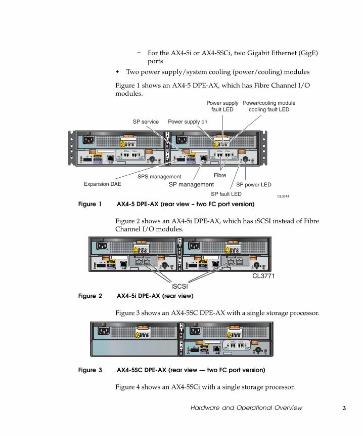
− For the AX4-5i or AX4-5SCi, two Gigabit Ethernet (GigE)ports
Two power supply/system cooling (power/cooling) modules
Figure 1 shows an AX4-5 DPE-AX, which has Fibre Channel I/Omodules.
FRU Label FRU Label
CL3914
Expansion DAESPS management
Power/cooling modulecooling fault LED
Power supplyfault LED
Power supply on
Fibre
SP service
SP management
SP fault LED
SP power LED
Figure 1 AX4-5 DPE-AX (rear view – two FC port version)
Figure 2 shows an AX4-5i DPE-AX, which has iSCSI instead of FibreChannel I/O modules.
FRU Label FRU Label
CL3771
iSCSI
Figure 2 AX4-5i DPE-AX (rear view)
Figure 3 shows an AX4-5SC DPE-AX with a single storage processor.
FRU Label FRU Label
CL3853
Figure 3 AX4-5SC DPE-AX (rear view — two FC port version)
Figure 4 shows an AX4-5SCi with a single storage processor.
Hardware and Operational Overview 3

FRU Label FRU Label
CL3854
Figure 4 AX4-5SCi DPE-AX (rear view)
AX4-5 and AX4-5i systems include a standby power supply (SPS); asecond SPS is optional. AX4-5 and AX4-5i systems support as many asfour optional disk array enclosures (DAE-AXs). Like the DPE-AX, eachDAE-AX includes two power/cooling modules and can contain a totalof twelve disk drives. Instead of SPs, a DAE-AX has two link controlcards (LCCs) that manage disks on a single redundant back-end bus.
You can install, upgrade, or replace all of the major storage-systemcomponents without professional assistance.
4 Hardware and Operational Overview

Disk and filler modules
Each DPE-AX includes at least four hard disk drives. The first fourdisks, marked 0-3, are system disks (sometimes called vault disks) andcontain vital software specific to the physical slot they occupy in thechassis. Do not move a system disk from its assigned slot to another slot.Remove a system disk only if you need to replace it because it failed.
SN
:12
34
AB
CD
12
34
AB
C1
23
BP
S
PN
:12
34
56
78
9R
EV
12
3
SATASATA 500500 GBGB 7.2K RPM7.2K RPM
SN
:12
34
AB
CD
12
34
AB
C1
23
BP
S
PN
:12
34
56
78
9R
EV
12
3
SATASATA 500500 GBGB 7.2K RPM7.2K RPM
SN
:12
34
AB
CD
12
34
AB
C1
23
BP
S
PN
:12
34
56
78
9R
EV
12
3
SATASATA 500500 GBGB 7.2K RPM7.2K RPM
SN
:12
34
AB
CD
12
34
AB
C1
23
BP
S
PN
:12
34
56
78
9R
EV
12
3
SATASATA 500500 GBGB 7.2K RPM7.2K RPM
SN
:12
34
AB
CD
12
34
AB
C1
23
BP
S
PN
:12
34
56
78
9R
EV
12
3
SATASATA 500500 GBGB 7.2K RPM7.2K RPM
SN
:12
34
AB
CD
12
34
AB
C1
23
BP
S
PN
:12
34
56
78
9R
EV
12
3
SATASATA 500500 GBGB 7.2K RPM7.2K RPM
SN
:12
34
AB
CD
12
34
AB
C1
23
BP
S
PN
:12
34
56
78
9R
EV
12
3
SATASATA 500500 GBGB 7.2K RPM7.2K RPM
SN
:12
34
AB
CD
12
34
AB
C1
23
BP
S
PN
:12
34
56
78
9R
EV
12
3
SATASATA 500500 GBGB 7.2K RPM7.2K RPM
SN
:12
34
AB
CD
12
34
AB
C1
23
BP
S
PN
:12
34
56
78
9R
EV
12
3
SATASATA 500500 GBGB 7.2K RPM7.2K RPM
SN
:12
34
AB
CD
12
34
AB
C1
23
BP
S
PN
:12
34
56
78
9R
EV
12
3
SATASATA 500500 GBGB 7.2K RPM7.2K RPM
SN
:12
34
AB
CD
12
34
AB
C1
23
BP
S
PN
:12
34
56
78
9R
EV
12
3
SATASATA 500500 GBGB 7.2K RPM7.2K RPM
SN
:12
34
AB
CD
12
34
AB
C1
23
BP
S
PN
:12
34
56
78
9R
EV
12
3
SATASATA 500500 GBGB 7.2K RPM7.2K RPM
CL3880
Figure 5 DPE-AX system (vault) disks
If a drive fails, you can replace it with another while the storage systemcontinues running; software rebuilds the contents of the original diskonto its replacement.
DPE-AX and DAE-AX chassis have twelve slots for disk modules. Anyunoccupied disk module slot requires a filler module to maintain airflow.
Disk modules
Each disk module, shown in Figure 6, consists of one disk drive in acarrier. You can add or remove a disk module while the storage systemis powered up, but you should exercise special care when removingdrives while they are in use.
Hardware and Operational Overview 5

EMC2830
Figure 6 Disk module
Disk drives
The disk drives are standard 3.5-inch (8.75-cm) by 1.0-inch (2.54-cm)serial advanced technology attachment (SATA) or serial attachedSCSI (SAS) drives. AX4–5 systems also support 2.5–inch SAS drivesmounted in 3.5–inch drive carriers. For a detailed list of supporteddisk drives and the minimum revision of the FLARE® operatingenvironment (OE) that supports each disk, refer to the Disk and FLAREOE Matrix under “Technical description” on the Learn page on thestorage-system support website or contact your service provider.
Drive carrier
The disk drive carrier is a plastic assembly that provides smooth,reliable contact with the enclosure slot guides and system boardconnectors. It has a handle with a latch and spring clips. The latchholds the disk module in place to ensure proper connection with theconnectors.
6 Hardware and Operational Overview

Storage processors (SPs)
The storage processor (SP) is the storage system’s intelligent componentand acts as the input/output (front end) and data storage (back end)control center. Besides the processor board and memory DIMM, eachSP includes an I/O module that determines the connection protocolto host servers.
DPE-AX systems with two SPs support write caching for increasedperformance. The redundant storage processors also provide highavailability should one SP fail or lose power.
Hardware and Operational Overview 7
Link control cards (LCCs)
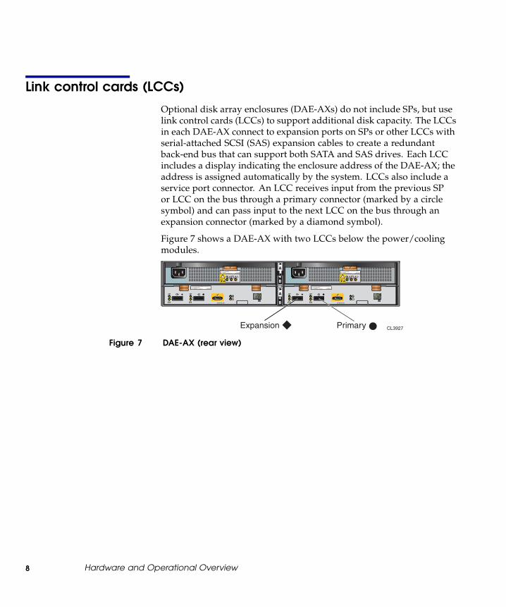
Optional disk array enclosures (DAE-AXs) do not include SPs, but uselink control cards (LCCs) to support additional disk capacity. The LCCsin each DAE-AX connect to expansion ports on SPs or other LCCs withserial-attached SCSI (SAS) expansion cables to create a redundantback-end bus that can support both SATA and SAS drives. Each LCCincludes a display indicating the enclosure address of the DAE-AX; theaddress is assigned automatically by the system. LCCs also include aservice port connector. An LCC receives input from the previous SPor LCC on the bus through a primary connector (marked by a circlesymbol) and can pass input to the next LCC on the bus through anexpansion connector (marked by a diamond symbol).
Figure 7 shows a DAE-AX with two LCCs below the power/coolingmodules.
CL3927
REV: AXX*AXX*
P/N: 118031924*118031924*
S/N: VVVYYWWRRRRR*VVVYYWWRRRRR*
REV: AXX*AXX*
P/N: 118031924*118031924*
S/N: VVVYYWWRRRRR*VVVYYWWRRRRR*
046-003-042_A03
#
FRU Label REV: AXX*AXX*
P/N: 118031924*118031924*
S/N: VVVYYWWRRRRR*VVVYYWWRRRRR*
046-003-042_A03
#
FRU Label REV: AXX*AXX*
P/N: 118031924*118031924*
S/N: VVVYYWWRRRRR*VVVYYWWRRRRR*
�� Expansion Primary
Figure 7 DAE-AX (rear view)
8 Hardware and Operational Overview

Power/cooling modules
Each power/cooling module integrates an independent power supplyand blowers into a single module. The power supply in each moduleis an auto-ranging, power-factor-corrected, multi-output, offlineconverter.
The power/cooling modules, A and B, are located above the SPsor LCCs. They share load currents and provide power and coolingfor an entire enclosure. An SP, LCC, or power/cooling module withpower-related faults does not adversely affect the operation of anyother component. If one power/cooling module fails, the othercompensates until the failed module is replaced. If the failed module isin a dual-SP DPE-AX, the system also disables write caching. Removinga power/cooling module from the enclosure causes a cooling fault thatwill shut down the enclosure within two minutes.
Hardware and Operational Overview 9

Standby power supplies (SPSs)
A 1U, 1000-watt SPS provides backup power for power supply A. Anoptional second SPS supports power supply B. During a power failure,the SPSs allow write caching to continue, which prevents data loss. Afaulted or not fully charged SPS disables the write cache. Each SPS rearpanel has one AC inlet power connector with power switch, AC outletsfor the DPE-AX SPs, and one connector for serial connection to an SP.Figure 8 shows the SPS connectors and status lights.
CL3881
AC powerconnector
Powerswitch
SPinterfaceDPE-AX
Active(green)
Replacebattery(amber)
On battery(amber)
Fault(amber)
Figure 8 1000–watt SPS connectors, power switch, and status lights
You can replace an SPS while the storage system is powered up.
10 Hardware and Operational Overview
Powerup and powerdown sequence
A DAE-AX does not have a power switch. It powers up immediately once itis connected to a live power source.
Powering up the storage system
1. Verify the following:
Master switch/circuit breakers for any cabinet/rack power stripare off.
The power cord for power/cooling module A in the DPE-AX(viewed from the rear, A is the right side of the enclosure) isplugged into the SPS, if present, and the power cord retentionbails are in place. In a storage system without an SPS, the powercord for power/cooling module A is plugged directly into apower source.
The power cord for power/cooling module B is plugged into thenearest power distribution unit on a different circuit feed thanthe SPS or module A. In systems with two SPSs, power/coolingmodule B is plugged into its corresponding SPS.
In a dual-SP system, the serial connection (sense cable) betweenSP A and SPS A is in place. If the system has two SPSs, the serialcable between SP B and SPS B is in place.
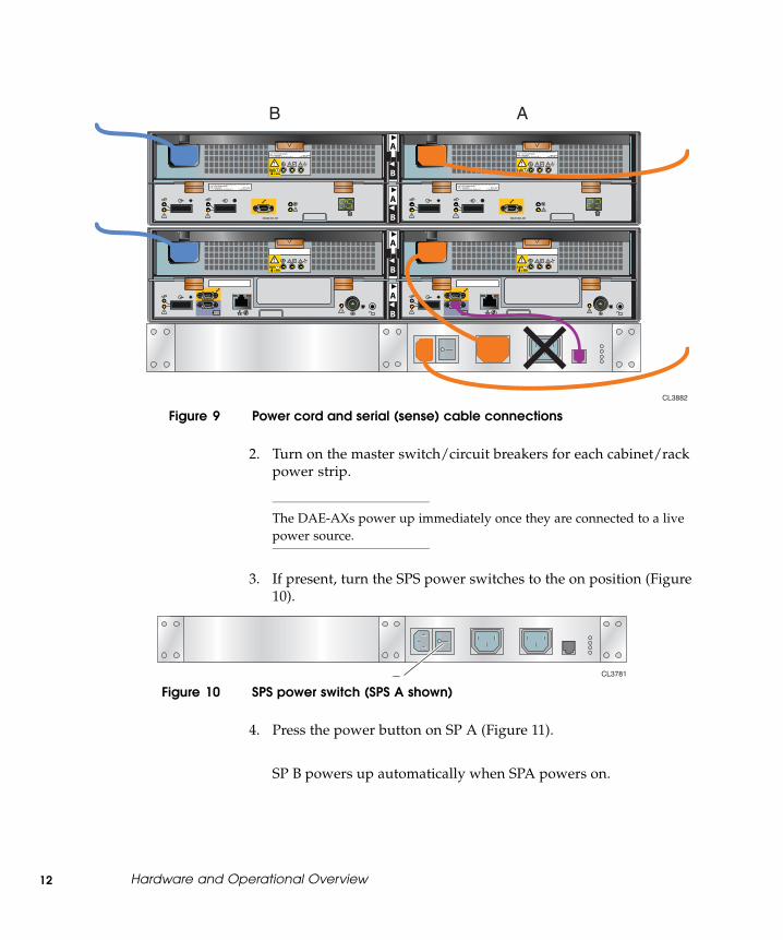
The power cords for the SPSs and any DAE-AXs are pluggedin; the power cords for the A and B sides do not share a powersource; and, the power cord retention bails are in place.
Any other devices in the cabinet are correctly installed andready for powerup.
Figure 9 shows a storage system with one SPS correctly cabled forhigh availability.
Hardware and Operational Overview 11
FRU Label FRU Label
REV: AXX*AXX*
P/N: 118031924*118031924*
S/N: VVVYYWWRRRRR*VVVYYWWRRRRR*
REV: AXX*AXX*
P/N: 118031924*118031924*
S/N: VVVYYWWRRRRR*VVVYYWWRRRRR*
046-003-042_A03
#
FRU Label REV: AXX*AXX*
P/N: 118031924*118031924*
S/N: VVVYYWWRRRRR*VVVYYWWRRRRR*
046-003-042_A03
#
FRU Label REV: AXX*AXX*
P/N: 118031924*118031924*
S/N: VVVYYWWRRRRR*VVVYYWWRRRRR*
CL3882
B A
Figure 9 Power cord and serial (sense) cable connections
2. Turn on the master switch/circuit breakers for each cabinet/rackpower strip.
The DAE-AXs power up immediately once they are connected to a livepower source.
3. If present, turn the SPS power switches to the on position (Figure10).
CL3781
Figure 10 SPS power switch (SPS A shown)
4. Press the power button on SP A (Figure 11).
SP B powers up automatically when SPA powers on.
12 Hardware and Operational Overview

FRU Label FRU Label
CL3766
Figure 11 SP power button
The storage system can take 5-6 minutes to complete its powerup.
If disk modules 0-3 shipped separately from your DPE-AX, the systemwrites vital information to those disks during the first powerup. Theprocess extends the first powerup by 25-30 minutes.
The system fault light on the front of the DPE-AX and the SPSrecharge lights on the rear of the SPS commonly stay on for severalminutes while the SPS fully charges.
SN
:12
34
AB
CD
12
34
AB
C1
23
BP
S
PN
:12
34
56
78
9R
EV
12
3
SATASATA 500500 GBGB 7.2K RPM7.2K RPM
SN
:12
34
AB
CD
12
34
AB
C1
23
BP
S
PN
:12
34
56
78
9R
EV
12
3
SATASATA 500500 GBGB 7.2K RPM7.2K RPM
SN
:12
34
AB
CD
12
34
AB
C1
23
BP
S
PN
:12
34
56
78
9R
EV
12
3
SATASATA 500500 GBGB 7.2K RPM7.2K RPM
SN
:12
34
AB
CD
12
34
AB
C1
23
BP
S
PN
:12
34
56
78
9R
EV
12
3
SATASATA 500500 GBGB 7.2K RPM7.2K RPM
SN
:12
34
AB
CD
12
34
AB
C1
23
BP
S
PN
:12
34
56
78
9R
EV
12
3
SATASATA 500500 GBGB 7.2K RPM7.2K RPM
SN
:12
34
AB
CD
12
34
AB
C1
23
BP
S
PN
:12
34
56
78
9R
EV
12
3
SATASATA 500500 GBGB 7.2K RPM7.2K RPM
SN
:12
34
AB
CD
12
34
AB
C1
23
BP
S
PN
:12
34
56
78
9R
EV
12
3
SATASATA 500500 GBGB 7.2K RPM7.2K RPM
SN
:12
34
AB
CD
12
34
AB
C1
23
BP
S
PN
:12
34
56
78
9R
EV
12
3
SATASATA 500500 GBGB 7.2K RPM7.2K RPM
SN
:12
34
AB
CD
12
34
AB
C1
23
BP
S
PN
:12
34
56
78
9R
EV
12
3
SATASATA 500500 GBGB 7.2K RPM7.2K RPM
SN
:12
34
AB
CD
12
34
AB
C1
23
BP
S
PN
:12
34
56
78
9R
EV
12
3
SATASATA 500500 GBGB 7.2K RPM7.2K RPMS
N:1
23
4A
BC
D1
23
4A
BC
12
3 B
PS
PN
:12
34
56
78
9R
EV
12
3
SATASATA 500500 GBGB 7.2K RPM7.2K RPM
SN
:12
34
AB
CD
12
34
AB
C1
23
BP
S
PN
:12
34
56
78
9R
EV
12
3
SATASATA 500500 GBGB 7.2K RPM7.2K RPM
+ - CL3761
Figure 12 DPE-AX system fault light and SPS recharge light
If any amber lights not related to the SPS recharge remain on for morethan 8-10 minutes, make sure the storage system is correctly cabled.Most amber lights indicate problems you can solve later, once your
Hardware and Operational Overview 13

storage system management software is available to help youtroubleshoot the system.
If the power buttons do not remain solid/steady green, contactyour authorized service provider.
Powering down the storage system
! CAUTION
Never shut down a DPE-AX by disconnecting the AC power cords forits power/cooling modules. Bypassing the controlled powerdown inthat manner prevents the system from saving any write cache data tothe system drives, and may result in data loss.
1. Stop all I/O activity to the DPE-AX. If the server connected to theDPE-AX is running the AIX, HP-UX, Linux, or Solaris operatingsystem, back up critical data and then unmount the file systemson storage-system virtual disks.
Stopping I/O allows the SP to save any cache data to the system drives,and may take some time. The length of time depends on criteria such as thesize of the cache, the amount of data in the cache, the type of data in thecache, and the target location on the disks, but it is typically less than oneminute. We recommend that you wait five minutes before proceeding.
2. For a dual-SP system, after five minutes, use the power switch oneach SPS to turn off power to its corresponding SP.
SPs with power/cooling modules connected to an SPS power downwithin two minutes.
3. Push the power button on SPs that are not connected to an SPS:
SP B in a single-SPS system
SP A in a single-SP DPE-AX
14 Hardware and Operational Overview
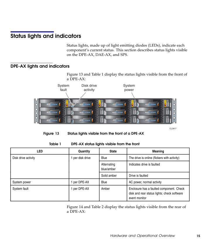
Status lights and indicators
Status lights, made up of light emitting diodes (LEDs), indicate eachcomponent’s current status. This section describes status lights visibleon the DPE-AX, DAE-AX, and SPS.
DPE-AX lights and indicators
Figure 13 and Table 1 display the status lights visible from the front ofa DPE-AX:
SN
:12
34
AB
CD
12
34
AB
C1
23
BP
S
PN
:12
34
56
78
9R
EV
12
3
SATASATA 500500 GBGB 7.2K RPM7.2K RPM
SN
:12
34
AB
CD
12
34
AB
C1
23
BP
S
PN
:12
34
56
78
9R
EV
12
3
SATASATA 500500 GBGB 7.2K RPM7.2K RPM
SN
:12
34
AB
CD
12
34
AB
C1
23
BP
S
PN
:12
34
56
78
9R
EV
12
3
SATASATA 500500 GBGB 7.2K RPM7.2K RPM
SN
:12
34
AB
CD
12
34
AB
C1
23
BP
S
PN
:12
34
56
78
9R
EV
12
3
SATASATA 500500 GBGB 7.2K RPM7.2K RPM
SN
:12
34
AB
CD
12
34
AB
C1
23
BP
S
PN
:12
34
56
78
9R
EV
12
3
SATASATA 500500 GBGB 7.2K RPM7.2K RPM
SN
:12
34
AB
CD
12
34
AB
C1
23
BP
S
PN
:12
34
56
78
9R
EV
12
3
SATASATA 500500 GBGB 7.2K RPM7.2K RPM
SN
:12
34
AB
CD
12
34
AB
C1
23
BP
S
PN
:12
34
56
78
9R
EV
12
3
SATASATA 500500 GBGB 7.2K RPM7.2K RPM
SN
:12
34
AB
CD
12
34
AB
C1
23
BP
S
PN
:12
34
56
78
9R
EV
12
3
SATASATA 500500 GBGB 7.2K RPM7.2K RPM
SN
:12
34
AB
CD
12
34
AB
C1
23
BP
S
PN
:12
34
56
78
9R
EV
12
3
SATASATA 500500 GBGB 7.2K RPM7.2K RPM
SN
:12
34
AB
CD
12
34
AB
C1
23
BP
S
PN
:12
34
56
78
9R
EV
12
3
SATASATA 500500 GBGB 7.2K RPM7.2K RPM
SN
:12
34
AB
CD
12
34
AB
C1
23
BP
S
PN
:12
34
56
78
9R
EV
12
3
SATASATA 500500 GBGB 7.2K RPM7.2K RPM
SN
:12
34
AB
CD
12
34
AB
C1
23
BP
S
PN
:12
34
56
78
9R
EV
12
3
SATASATA 500500 GBGB 7.2K RPM7.2K RPM
Disk driveactivity
Systemfault
Systempower
CL3917
Figure 13 Status lights visible from the front of a DPE-AX
Table 1 DPE-AX status lights visible from the front
LED Quantity State Meaning
Blue The drive is online (flickers with activity)
Alternatingblue/amber
Indicates drive is faulted
Disk drive activity 1 per disk drive
Solid amber Drive is faulted
System power 1 per DPE-AX Blue AC power, normal activity
System fault 1 per DPE-AX Amber Enclosure has a faulted component. Checkdisk and rear status lights; check softwareevent monitor
Figure 14 and Table 2 display the status lights visible from the rear ofa DPE-AX:
Hardware and Operational Overview 15

FRU Label FRU Label
CL3916
Power supplyfault Cooling fault
Power supply on/off
Fibre
SP management SP fault SP power
Figure 14 DPE-AX lights visible from the rear (2–port Fibre Channel I/O module shown )
Table 2 Meaning of the DPE-AX status lights visible from the rear
LED Quantity State Meaning
Solid green SP is running normally
Blinking green Operating system is booting
SP power 1 per SP
Off No power or shutting down
Solid amber SP has encountered a problemSP fault 1 per SP
Off SP is operating normally or is shut down
Solid green On the left, this indicates an established linkSP management 2
Blinking green On the right, this indicates normal activity
Solid green Indicates a 1–2 Gb link
Solid blue Indicates a 4 Gb link
Fibre Channel 2 per SP
Off No link has been established
Solid green Indicates a 1–2 Gb link
Solid blue Indicates a 4 Gb link
iSCSI 2 per SP
Off No link has been established
Solid amber Power supply is faulted
Blinking amber Power supply is not seated
Power supply fault 1 per power supply
Off Indicates normal activity
16 Hardware and Operational Overview

LED Quantity State Meaning
Solid green Indicates ac power and normal acitvityPower supply on/off 1 per power supply
Off No ac power
Solid amber Indicates a cooling faultCooling fault 1 per powersupply/system coolingmodule
Off Indicates blower is operating normally
DAE-AX status lights and indicators
Figure 15 and Table 3 display the meaning of the status lights on thefront of a DAE-AX:
SN
:12
34
AB
CD
12
34
AB
C1
23
BP
S
PN
:12
34
56
78
9R
EV
12
3
SATASATA 500500 GBGB 7.2K RPM7.2K RPM
SN
:12
34
AB
CD
12
34
AB
C1
23
BP
S
PN
:12
34
56
78
9R
EV
12
3
SATASATA 500500 GBGB 7.2K RPM7.2K RPM
SN
:12
34
AB
CD
12
34
AB
C1
23
BP
S
PN
:12
34
56
78
9R
EV
12
3
SATASATA 500500 GBGB 7.2K RPM7.2K RPM
SN
:12
34
AB
CD
12
34
AB
C1
23
BP
S
PN
:12
34
56
78
9R
EV
12
3
SATASATA 500500 GBGB 7.2K RPM7.2K RPM
SN
:12
34
AB
CD
12
34
AB
C1
23
BP
S
PN
:12
34
56
78
9R
EV
12
3
SATASATA 500500 GBGB 7.2K RPM7.2K RPM
SN
:12
34
AB
CD
12
34
AB
C1
23
BP
S
PN
:12
34
56
78
9R
EV
12
3
SATASATA 500500 GBGB 7.2K RPM7.2K RPM
SN
:12
34
AB
CD
12
34
AB
C1
23
BP
S
PN
:12
34
56
78
9R
EV
12
3
SATASATA 500500 GBGB 7.2K RPM7.2K RPM
SN
:12
34
AB
CD
12
34
AB
C1
23
BP
S
PN
:12
34
56
78
9R
EV
12
3
SATASATA 500500 GBGB 7.2K RPM7.2K RPM
SN
:12
34
AB
CD
12
34
AB
C1
23
BP
S
PN
:12
34
56
78
9R
EV
12
3
SATASATA 500500 GBGB 7.2K RPM7.2K RPM
SN
:12
34
AB
CD
12
34
AB
C1
23
BP
S
PN
:12
34
56
78
9R
EV
12
3
SATASATA 500500 GBGB 7.2K RPM7.2K RPM
SN
:12
34
AB
CD
12
34
AB
C1
23
BP
S
PN
:12
34
56
78
9R
EV
12
3
SATASATA 500500 GBGB 7.2K RPM7.2K RPM
SN
:12
34
AB
CD
12
34
AB
C1
23
BP
S
PN
:12
34
56
78
9R
EV
12
3
SATASATA 500500 GBGB 7.2K RPM7.2K RPM
Disk driveactivity
Systemfault
Systempower
CL3917
Figure 15 Status lights visible from the front of a DAE-AX
Table 3 DAE-AX status lights visible from the front
LED Quantity State Meaning
Blue The drive is online with Flare(flickers with activity)
Alternating blue/amber Indicates drive is faulted
Disk drive activity 1 per disk drive
Solid amber Drive is faulted
System fault 1 per DAE-AX Amber Enclosure has a faultedcomponent. Check disk andrear status lights; check softwareevent monitor
System power 1 per DAE-AX Blue AC power, normal activity
Figure 16 and Table 4 display the status lights visible from the rear ofa DAE-AX:
Hardware and Operational Overview 17

REV: AXX*AXX*
P/N: 118031924*118031924*
S/N: VVVYYWWRRRRR*VVVYYWWRRRRR*
REV: AXX*AXX*
P/N: 118031924*118031924*
S/N: VVVYYWWRRRRR*VVVYYWWRRRRR*
046-003-042_A03
#
FRU Label REV: AXX*AXX*
P/N: 118031924*118031924*
S/N: VVVYYWWRRRRR*VVVYYWWRRRRR*
046-003-042_A03
#
FRU Label REV: AXX*AXX*
P/N: 118031924*118031924*
S/N: VVVYYWWRRRRR*VVVYYWWRRRRR*
CL3915
Power supplyon/off
LCCconnectivity
LCC connection fault LCC fault
LCC powerCooling fault
Power supply fault
Enclosure number
Figure 16 Status lights visible from the rear of a DAE-AX
Table 4 DAE-AX status lights visible from the rear
LED Quantity State Meaning
Solid green LCC is receiving ac powerLCC power 1 per LCC
Off No power
LCC fault 1 per LCC Solid amber LCC has encountered a problem
Solid green Indicates normal connectionLCC connectivity 2 per LCC
Blinking green Connection is expected, but is notdetected
Solid amber Indicates a connection problem.LCC connection fault 2 per LCC
Blinking amber Indicates a problem with the connection.
Solid amber Power supply is faulted
Blinking amber Power supply is not seated
Power supply fault 1 per power supply
Off Indicates normal activity
Solid green Indicates ac power and normal acitvityPower supply on/off 1 per power supply
Off No ac power
Solid amber Indicates a cooling faultCooling fault 1 per powersupply/systemcooling module
Off Indicates blower is operating normally
18 Hardware and Operational Overview

Flashing dashes Not accessible or initializing at thebeginning of powerup
Number displayed (solid) Online to Flare
Enclosure number 1 per LCC
Number displayed (blinking) Flare has lost connection with enclosure
Standby power supply LEDs
Figure 17 and Table 5 display the meaning of the SPS status lights:
CL3918
On battery(amber)
Active(green)
Replacebattery(amber)
Fault(amber)
Figure 17 SPS status lights and indicators
Table 5 Standby power supply (SPS) status lights and indicators
LED Quantity State Meaning
Solid green SPS is operating normallySPS active 1 per SPS
Blinking green SPS is charging
SPS fault 1 per SPS Solid amber The SPS has encountered an internal problem
On battery 1 per SPS Solid amber The storage system is either testing the SPS batteryor is running on battery due to lack of ac power tothe SPS
Replace battery 1 per SPS Solid amber The battery is not working properly
Hardware and Operational Overview 19
Copyright © 2007–2010 EMC Corporation. All Rights Reserved.
EMC believes the information in this publication is accurate as of its publication date. Theinformation is subject to change without notice.
THE INFORMATION IN THIS PUBLICATION IS PROVIDED "AS IS." EMC CORPORATIONMAKES NO REPRESENTATIONS OR WARRANTIES OF ANY KIND WITH RESPECT TOTHE INFORMATION IN THIS PUBLICATION, AND SPECIFICALLY DISCLAIMS IMPLIEDWARRANTIES OF MERCHANTABILITY OR FITNESS FOR A PARTICULAR PURPOSE.
Use, copying, and distribution of any EMC software described in this publication requires anapplicable software license. Trademark Information
For the most up-to-date regulatory document for your product line, go to the TechnicalDocumentation and Advisories section on EMC Powerlink.
For the most up-to-date listing of EMC product names, see EMC Corporation Trademarks onEMC.com.
All other trademarks used herein are the property of their respective owners.
20 Hardware and Operational Overview