aware vehicle intelligence installation manual for
TRANSCRIPT

1 March 7, 2008
AWARE VEHICLE INTELLIGENCETM
INSTALLATION MANUAL
FOR INTERNATIONAL® TRUCKS
4700, 4900, 8100 and 8200
MODULES ARE NOT ACTIVATED WHEN SHIPPED. PLEASE SEE THE ACTIVATION GUIDE.
2 March 7, 2008
TABLE OF CONTENTS 1. AWARETM Vehicle Models ...........................................................................................................3
1.1. Before Installing......................................................................................................................3 1.2. FCC RF Exposure Information...............................................................................................3
2. How the system works ....................................................................................................................3 3. Kit Installation Components ...........................................................................................................4
3.1. 4700 & 4900 Kit Components ................................................................................................4 3.2. Driver Alert Kit Components (Optional)................................................................................4 3.3. Components Provided by Installer..........................................................................................4
4. AWARE Module Installation .........................................................................................................6 4.1. Fastened to Tranmission Cover ..............................................................................................6 4.2. Fastened to Underside of Dash ...............................................................................................7
5. AWARE Main Harness Installation................................................................................................8 5.1. Battery, Ignition & Ground.....................................................................................................9 5.2. J1708/J1587 Connection.......................................................................................................11 5.3. J1939 Connection..................................................................................................................12
5.3.1. 6-Pin Gray Connector ...................................................................................................13 5.3.2. 9-Pin Black Connector..................................................................................................14
5.4. Accessory Equipment Monitoring Connection.....................................................................16 5.4.1. Fuel Sender ...................................................................................................................16 5.4.2. Park Brake.....................................................................................................................17 5.4.3. Service Brake ................................................................................................................18
6. Antenna Installation ......................................................................................................................18 7. Driver Alert Switch Installation (Optional) ..................................................................................21 8. Software Upgrade .........................................................................................................................22 9. Configuration ................................................................................................................................24
9.1. Download Templates ............................................................................................................24 9.1.1. Dealers ..........................................................................................................................24 9.1.2. Customers .....................................................................................................................24
9.2. Import Templates into Diamond Logic® Builder.................................................................24 9.3. Apply Templates to module..................................................................................................25 9.4. Program Templates to module ..............................................................................................25
10. Activation..................................................................................................................................26 11. Final Assembly Steps................................................................................................................27
APPENDIX A Program Parameters Manually......................................................................................................28 B AWARE Module LED Troubleshooting Table ............................................................................30

3 March 7, 2008
1. AWARETM Vehicle Models This installation procedure is for the International® QSP Series. Applicable models include International® 4700, 4900, 8100 and 8200. Other vehicles may not be similar.
1.1. Before Installing Please read this entire document prior to installing the AWARE module. Pay attention to all Cautions and Warnings.
CAUTION: Unauthorized antennas, modifications, or attachments could impair call quality, damage the module, or result in violation of FCC regulations. Do not use the module with a damaged antenna. Please contact your local authorized International®
dealer for antenna replacement.
WARNING: To avoid property damage, personal injury, or death, park the vehicle on a flat level surface, set the parking brake, turn the engine off, and chock the wheels.
1.2. FCC RF Exposure Information In August 1996 the Federal Communications Commission (FCC) of the United States with its action in Report and Order FCC 96-326 adopted an updated safety standard for human exposure to radio frequency electromagnetic energy emitted by FCC regulated transmitters. Those guidelines are consistent with the safety standard previously set by both U.S. and international standards bodies. The design of this cellular module complies with the FCC guidelines and these international standards.
WARNING: While the system is in operation, a separation distance of at least 20 centimeters (approximately 8 inches) must be maintained between the cellular antenna and the body of all persons in order to meet the FCC RF exposure guidelines.
2. How the system works The AWARE module is a data collection and communication system mounted on a vehicle. It consists of a GPS and cellular antenna and a data communicator module. The data communicator module collects the vehicle�s location and system information and sends it to
the network control center through wireless technology.
4 March 7, 2008
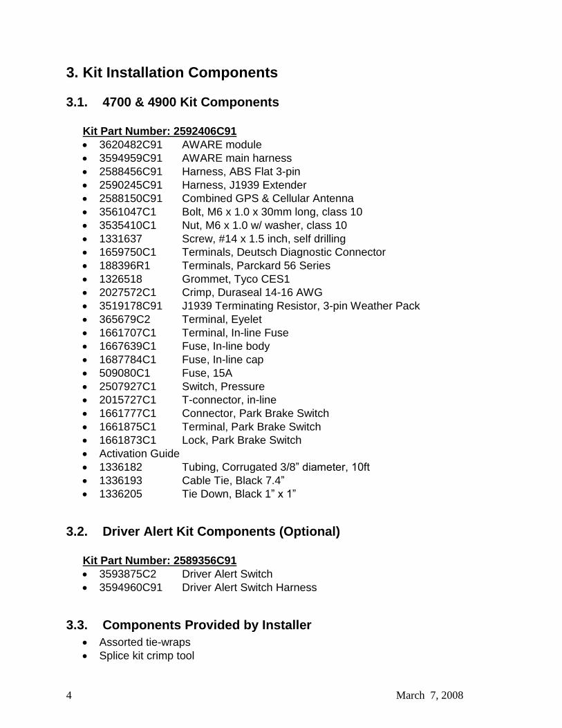
3. Kit Installation Components
3.1. 4700 & 4900 Kit Components
Kit Part Number: 2592406C91 3620482C91 AWARE module 3594959C91 AWARE main harness 2588456C91 Harness, ABS Flat 3-pin 2590245C91 Harness, J1939 Extender 2588150C91 Combined GPS & Cellular Antenna 3561047C1 Bolt, M6 x 1.0 x 30mm long, class 10 3535410C1 Nut, M6 x 1.0 w/ washer, class 10 1331637 Screw, #14 x 1.5 inch, self drilling 1659750C1 Terminals, Deutsch Diagnostic Connector 188396R1 Terminals, Parckard 56 Series 1326518 Grommet, Tyco CES1 2027572C1 Crimp, Duraseal 14-16 AWG 3519178C91 J1939 Terminating Resistor, 3-pin Weather Pack 365679C2 Terminal, Eyelet 1661707C1 Terminal, In-line Fuse 1667639C1 Fuse, In-line body 1687784C1 Fuse, In-line cap 509080C1 Fuse, 15A 2507927C1 Switch, Pressure 2015727C1 T-connector, in-line 1661777C1 Connector, Park Brake Switch 1661875C1 Terminal, Park Brake Switch 1661873C1 Lock, Park Brake Switch Activation Guide 1336182 Tubing, Corrugated 3/8� diameter, 10ft 1336193 Cable Tie, Black 7.4� 1336205 Tie Down, Black 1� x 1�
3.2. Driver Alert Kit Components (Optional)
Kit Part Number: 2589356C91 3593875C2 Driver Alert Switch 3594960C91 Driver Alert Switch Harness
3.3. Components Provided by Installer Assorted tie-wraps Splice kit crimp tool

5 March 7, 2008
Diamond Logic® Builder Service tool for programming / provisioning module EZ-Tech® COM cable (IC3 or IC4)

6 March 7, 2008
4. AWARE Module Installation
Figure 1 - Module antenna plugs
Figure 2 - Module connector locations
The AWARE module should be mounted in the middle of the cab, below the dash panel. It can be fastened using two different methods:
a. Fastened to transmission cover See Section 4.1
b. Fasten to underside of dash See Section 4.2
4.1. Fastened to Tranmission Cover 1. Remove the transmission cover (doghouse) over the transmission. 2. Align the module on the top of transmission cover with the module connectors toward
the driver side door and the antenna connectors toward the passenger side door. 3. Mount module to top of transmission cover using self-drilling / self-tapping screws.
GPS Antenna
Cellular Antenna
J1 Connector (Color: Black)
J2 Connector (Color: Gray)
7 March 7, 2008
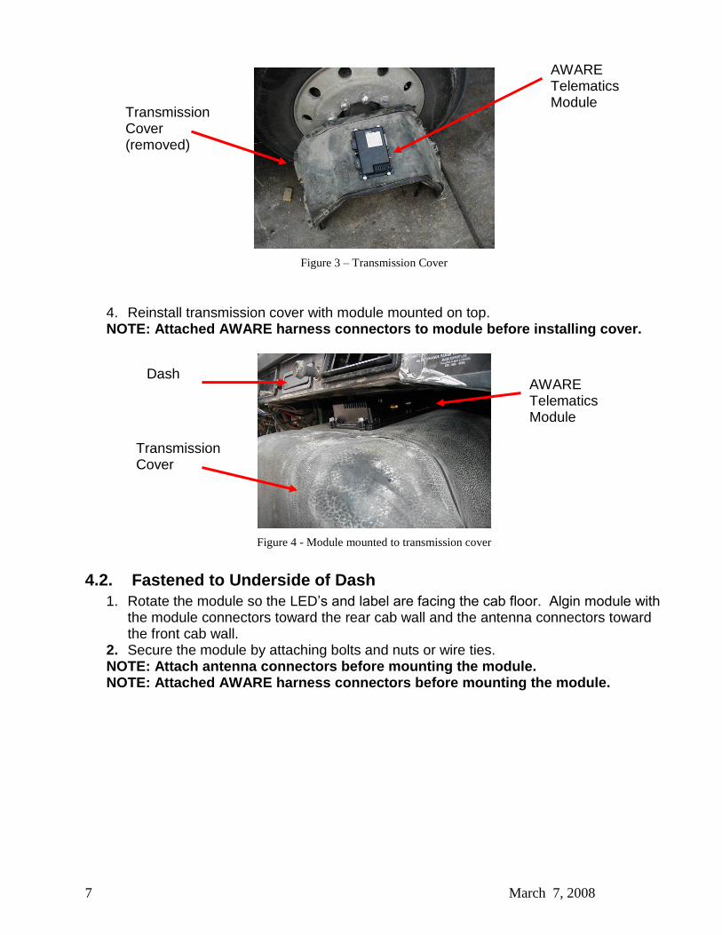
Figure 3 � Transmission Cover
4. Reinstall transmission cover with module mounted on top. NOTE: Attached AWARE harness connectors to module before installing cover.
Figure 4 - Module mounted to transmission cover
4.2. Fastened to Underside of Dash 1. Rotate the module so the LED�s and label are facing the cab floor. Algin module with
the module connectors toward the rear cab wall and the antenna connectors toward the front cab wall.
2. Secure the module by attaching bolts and nuts or wire ties. NOTE: Attach antenna connectors before mounting the module. NOTE: Attached AWARE harness connectors before mounting the module.
AWARE Telematics Module
Transmission Cover (removed)
Transmission Cover
AWARE Telematics Module
Dash
8 March 7, 2008
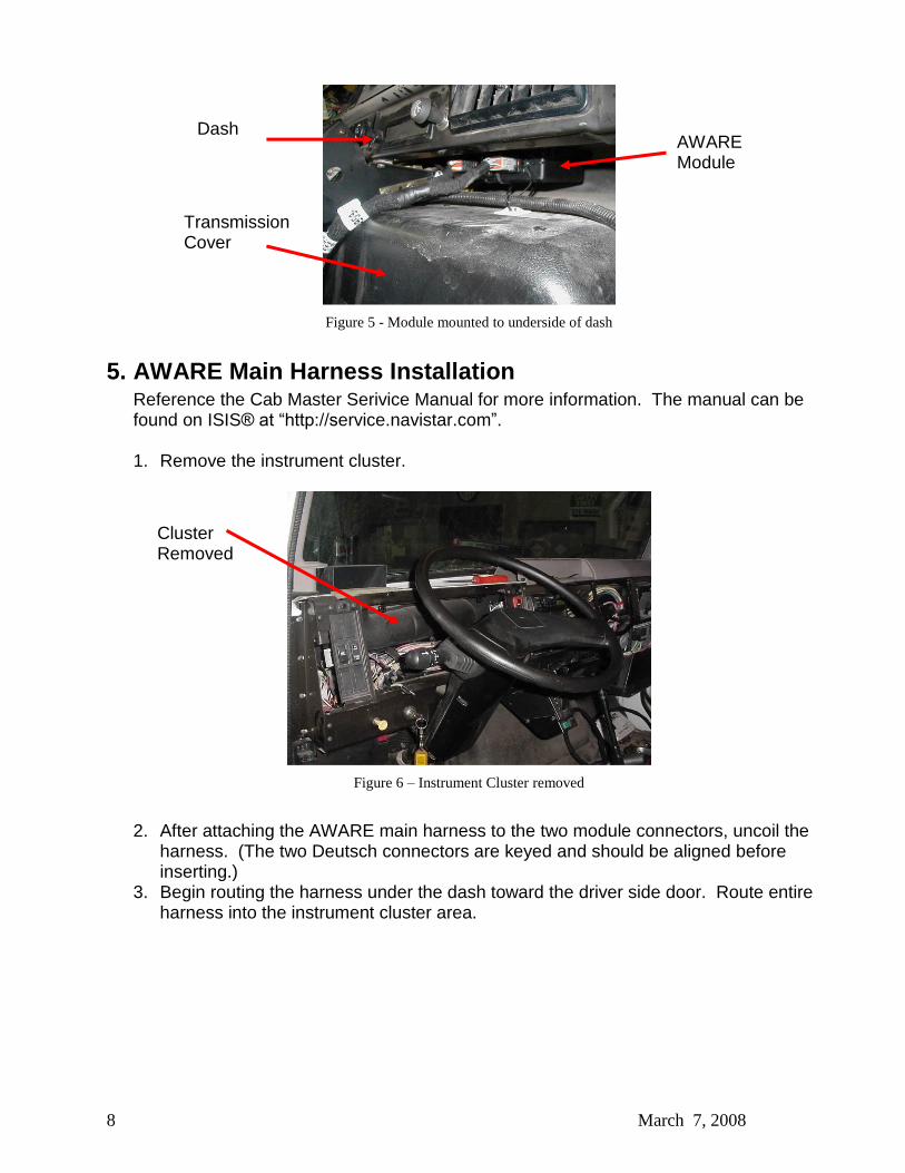
Figure 5 - Module mounted to underside of dash
5. AWARE Main Harness Installation Reference the Cab Master Serivice Manual for more information. The manual can be found on ISIS® at �http://service.navistar.com�. 1. Remove the instrument cluster.
Figure 6 � Instrument Cluster removed
2. After attaching the AWARE main harness to the two module connectors, uncoil the
harness. (The two Deutsch connectors are keyed and should be aligned before inserting.)
3. Begin routing the harness under the dash toward the driver side door. Route entire harness into the instrument cluster area.
Transmission Cover
AWARE Module
Dash
Cluster Removed

9 March 7, 2008
Figure 7 � Aware harness in dash
5.1. Battery, Ignition & Ground 1. Locate the BATTERY (red) wire from the AWARE harness. 2. Assemble the in-line fuse:
a. Cut the BATTERY wire 8 inches from the end. b. Crimp an in-line fuse terminals to one end of the 8 inch wire segment and to
the end of the BATTERY wire on the Aware harness. c. Insert the terminals into the in-line fuse body housing. d. Insert the 15A fuse into the body housing. e. Attach the fuse cap over the fuse.
Figure 8 � In-line fuse
3. Crimp an I-terminal (eyelet terminal) to the end of the BATTERY wire. 4. Locate the battery power stud located on the left side of the instrument panel.
AWARE Harness
Fuse Cap
AWARE Harness
8� wire
segment (Attach I-terminal)
Fuse

10 March 7, 2008
Figure 9 � Battery Stud
5. Fasten the BATTERY wire I-terminal to the Battery stud. 6. Locate the IGNITION (pink) wire from the AWARE harness. 7. Locate an white (natural) instrument cluster connector, composite 28. 8. Locate ignition feed which is pink circuit 18-G in cavity 5.
Figure 10 � Ignition Circuit
9. Splice, crimp and heat shrink.
10. Locate the GROUND (white) wire in the AWARE harness. 11. Locate the ground stud located on the left side of the instrument panel.
Battery Stud
Cluster Connector Ignition Feed

11 March 7, 2008
Figure 11 � Ground stud
12. Crimp an I-terminal (eyelet terminal) to the end of the GROUND wire. 13. Fasten the GROUND wire I-terminal to the Ground stud.
5.2. J1708/J1587 Connection 1. Locate the blunt cut J1708/J1587 twisted pair of wires (blue & gray) from the AWARE
harness and route them to the splice packs located behind the instrument cluster.
Figure 12 � J1708/J1587 splice packs
2. Cut the wires to length required and attach the splice pack terminals provided in the
kit. 3. Insert J1708/J1587+ (blue) wire into RED splice pack, composite 427. 4. Insert J1708/J1587- (gray) wire into BLUE splice pack, composite 428.
Ground stud
J1708/J1587 Red = Positive
J1708/J1587 Blue = Negative
12 March 7, 2008
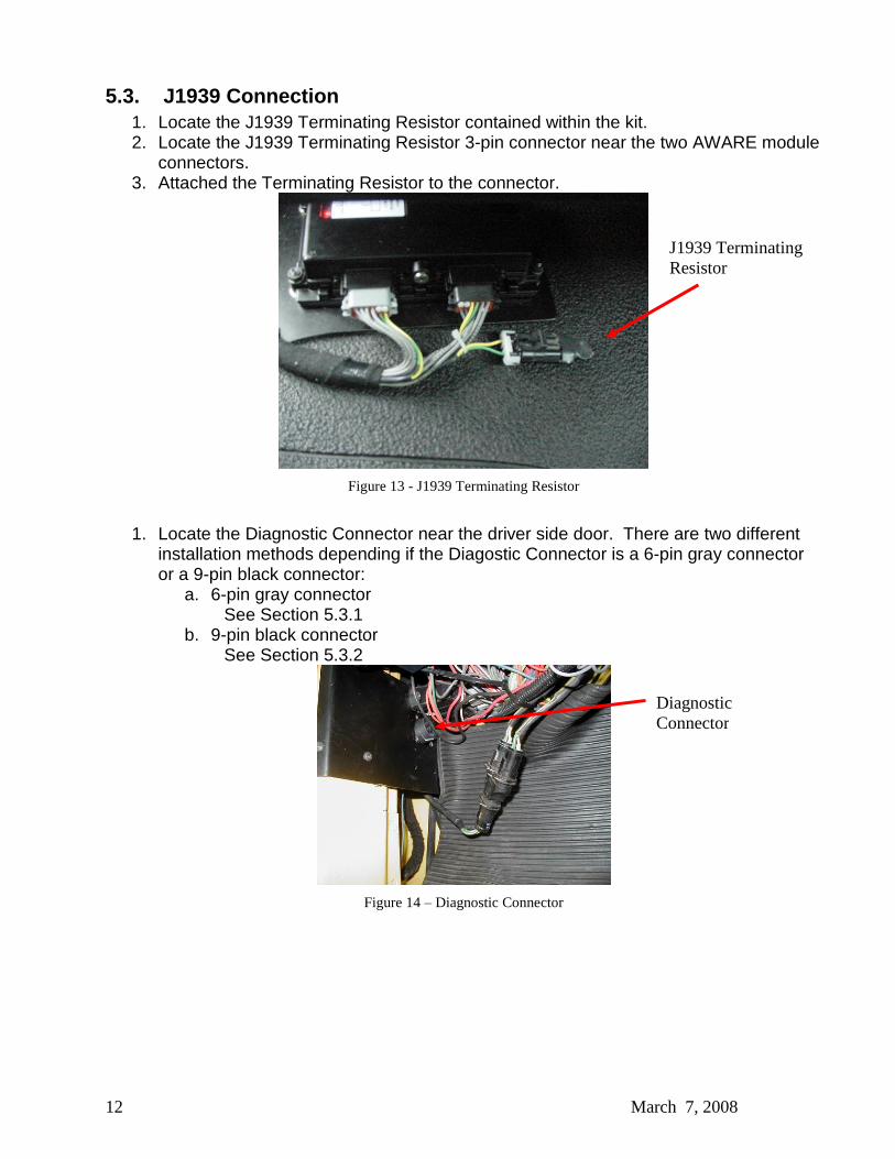
5.3. J1939 Connection 1. Locate the J1939 Terminating Resistor contained within the kit. 2. Locate the J1939 Terminating Resistor 3-pin connector near the two AWARE module
connectors. 3. Attached the Terminating Resistor to the connector.
Figure 13 - J1939 Terminating Resistor
1. Locate the Diagnostic Connector near the driver side door. There are two different
installation methods depending if the Diagostic Connector is a 6-pin gray connector or a 9-pin black connector:
a. 6-pin gray connector See Section 5.3.1
b. 9-pin black connector See Section 5.3.2
Figure 14 � Diagnostic Connector
J1939 Terminating Resistor
Diagnostic Connector

13 March 7, 2008
5.3.1. 6-Pin Gray Connector In this method, a dedicated J1939 network will be created for the AWARE module.
-�����
&RQQHFWRU
-�����
&RQQHFWRU
-�����
&RQQHFWRU
7HUPLQDWLQJ�
5HVLVWRU
-�����$%6�+DUQHVV
$ZDUH��7HOHPDWLFV�+DUQHVV
-�����&RQQHFWLRQ�ZLWK�$ZDUH�+DUQHVV��$%6�+DUQHVV
$ZDUH��
7HOHPDWLFV�
0RGXOH
-�����
&RQQHFWRU
��3LQ�
'LDJQRVWLF�
&RQQHFWRU
Figure 15 � 6-Pin Diagnostic Connector, Configuration with J1939 ABS Harness
4. Attach the male J1939 connector on the ABS Harness to the female J1939 connector
on the AWARE main harness. 5. Tie the female J1939 connector on the ABS Harness to the main cab harness. This
connector is not used in this application. 6. Remove the 6-pin diagnostic connector. 7. Cut off all four wires close to the connector back shell. 8. Re-terminate the four wires with the Deutsch terminals provided in the kit. 9. Insert the four wires in the 9-pin diagnostic connector that is part of the J1939 ABS
harness. See the attached pin out chart for the 9-pin diagnostic connector as a guide.
14 March 7, 2008
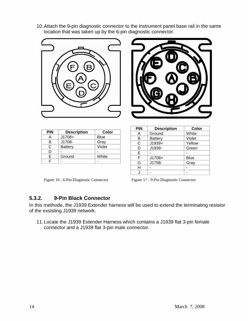
10. Attach the 9-pin diagnostic connector to the instrument panel base rail in the same location that was taken up by the 6-pin diagnostic connector.
PIN Description Color A J1708+ Blue B J1708- Gray C Battery Violet D - - E Ground White F - -
Figure 16 - 6-Pin Diagnostic Connector Figure 17 - 9-Pin Diagnostic Connector
5.3.2. 9-Pin Black Connector In this methode, the J1939 Extender harness will be used to extend the terminating resistor of the exsisting J1939 network.
11. Locate the J1939 Extender Harness which contains a J1939 flat 3-pin female
connector and a J1939 flat 3-pin male connector.
PIN Description Color A Ground White B Battery Violet C J1939+ Yellow D J1939- Green E - - F J1708+ Blue G J1708- Gray H - - J - -
15 March 7, 2008
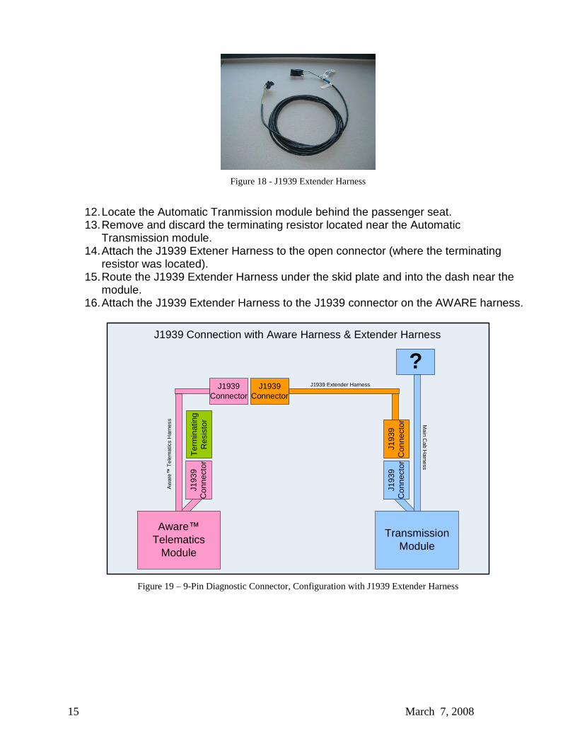
Figure 18 - J1939 Extender Harness
12. Locate the Automatic Tranmission module behind the passenger seat. 13. Remove and discard the terminating resistor located near the Automatic
Transmission module. 14. Attach the J1939 Extener Harness to the open connector (where the terminating
resistor was located). 15. Route the J1939 Extender Harness under the skid plate and into the dash near the
module. 16. Attach the J1939 Extender Harness to the J1939 connector on the AWARE harness.
?J1939
ConnectorJ1939
Connector
J193
9 C
onne
ctor
Ter
min
atin
g R
esis
tor
J1939 Extender Harness
Aw
are�
Tel
emat
ics
Har
ness M
ain Cab H
arness
J1939 Connection with Aware Harness & Extender Harness
Aware�
Telematics Module
J193
9 C
onne
ctor
Transmission Module
J193
9 C
onne
ctor
Figure 19 � 9-Pin Diagnostic Connector, Configuration with J1939 Extender Harness
16 March 7, 2008
5.4. Accessory Equipment Monitoring Connection
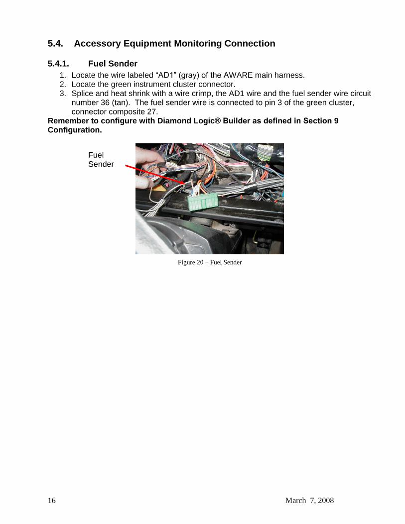
5.4.1. Fuel Sender 1. Locate the wire labeled �AD1� (gray) of the AWARE main harness. 2. Locate the green instrument cluster connector. 3. Splice and heat shrink with a wire crimp, the AD1 wire and the fuel sender wire circuit
number 36 (tan). The fuel sender wire is connected to pin 3 of the green cluster, connector composite 27.
Remember to configure with Diamond Logic® Builder as defined in Section 9 Configuration.
Figure 20 � Fuel Sender
Fuel Sender
17 March 7, 2008
5.4.2. Park Brake
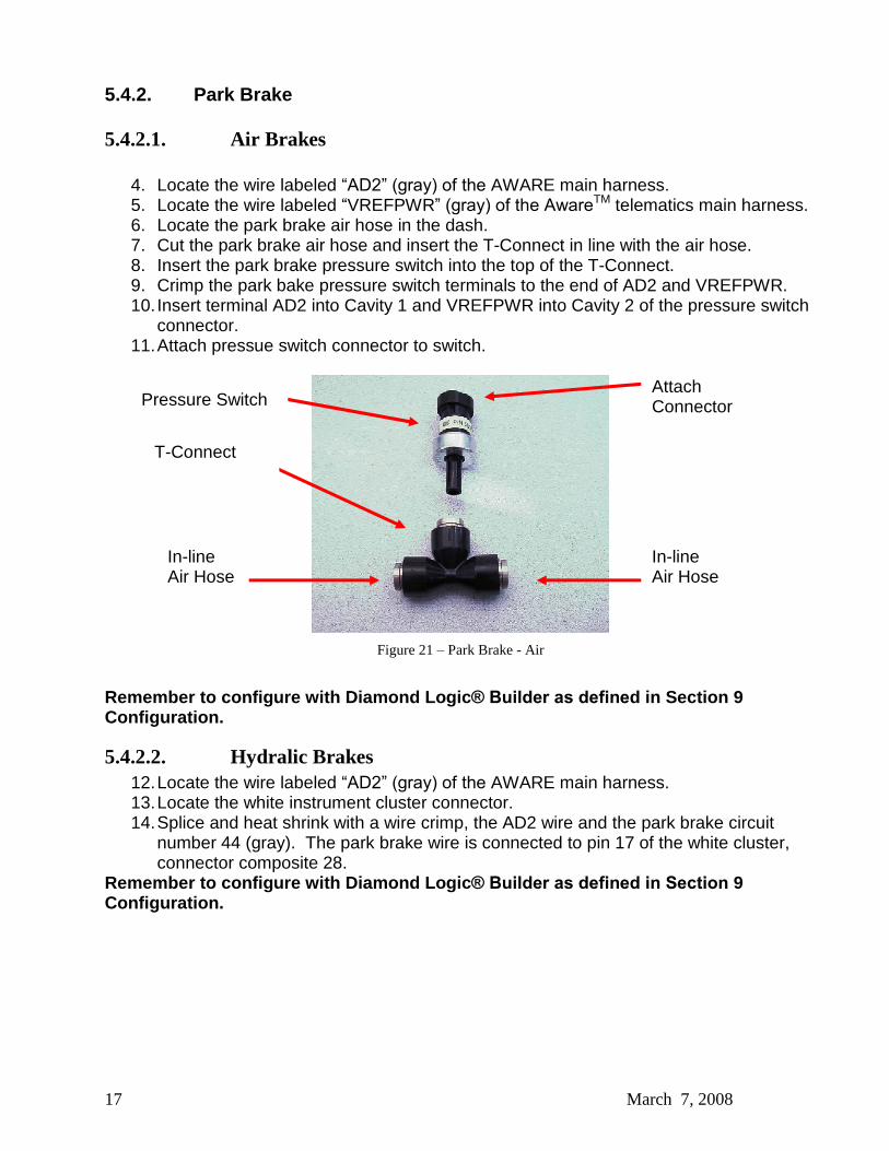
5.4.2.1. Air Brakes
4. Locate the wire labeled �AD2� (gray) of the AWARE main harness. 5. Locate the wire labeled �VREFPWR� (gray) of the Aware
TM telematics main harness. 6. Locate the park brake air hose in the dash. 7. Cut the park brake air hose and insert the T-Connect in line with the air hose. 8. Insert the park brake pressure switch into the top of the T-Connect. 9. Crimp the park bake pressure switch terminals to the end of AD2 and VREFPWR. 10. Insert terminal AD2 into Cavity 1 and VREFPWR into Cavity 2 of the pressure switch
connector. 11. Attach pressue switch connector to switch.
Figure 21 � Park Brake - Air
Remember to configure with Diamond Logic® Builder as defined in Section 9 Configuration.
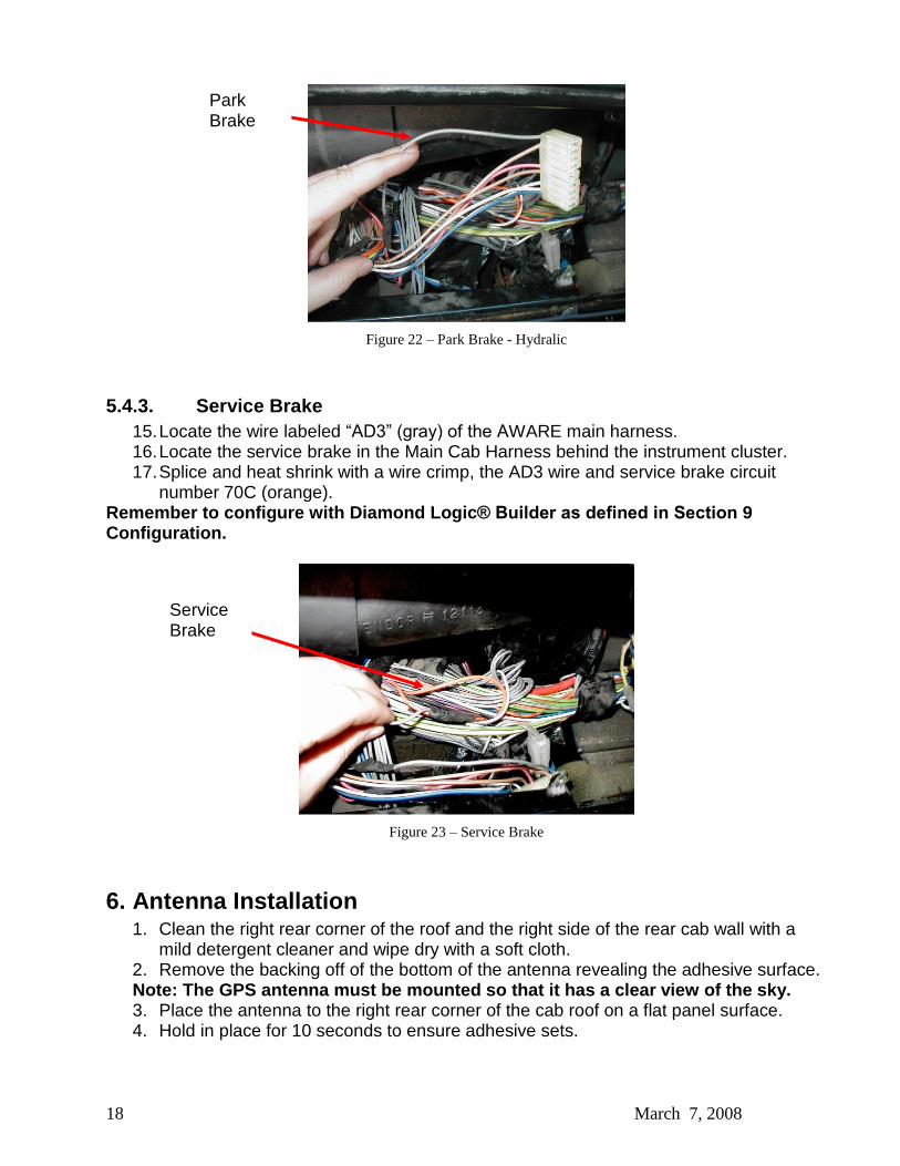
5.4.2.2. Hydralic Brakes 12. Locate the wire labeled �AD2� (gray) of the AWARE main harness. 13. Locate the white instrument cluster connector. 14. Splice and heat shrink with a wire crimp, the AD2 wire and the park brake circuit
number 44 (gray). The park brake wire is connected to pin 17 of the white cluster, connector composite 28.
Remember to configure with Diamond Logic® Builder as defined in Section 9 Configuration.
T-Connect
Pressure Switch
In-line Air Hose
Attach Connector
In-line Air Hose
18 March 7, 2008
Figure 22 � Park Brake - Hydralic
5.4.3. Service Brake 15. Locate the wire labeled �AD3� (gray) of the AWARE main harness. 16. Locate the service brake in the Main Cab Harness behind the instrument cluster. 17. Splice and heat shrink with a wire crimp, the AD3 wire and service brake circuit
number 70C (orange). Remember to configure with Diamond Logic® Builder as defined in Section 9 Configuration.
Figure 23 � Service Brake
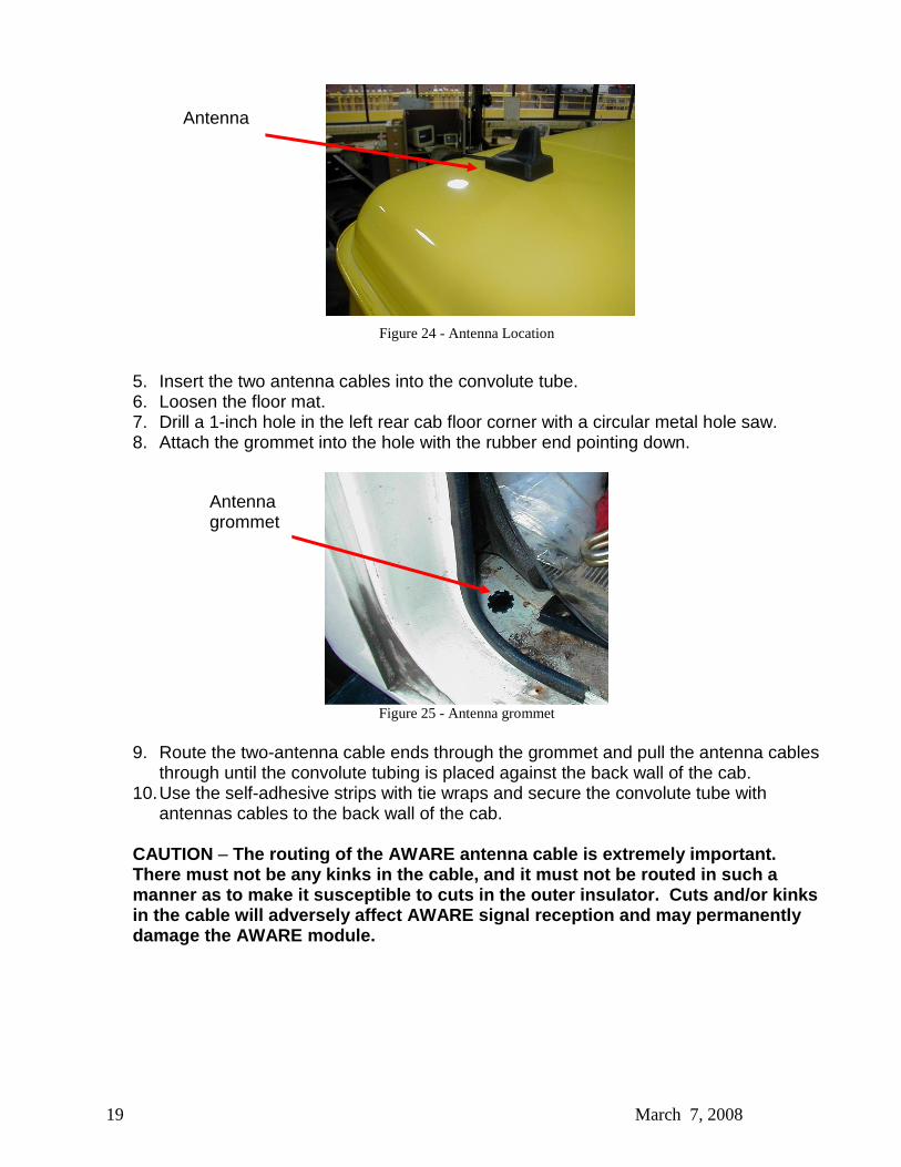
6. Antenna Installation 1. Clean the right rear corner of the roof and the right side of the rear cab wall with a
mild detergent cleaner and wipe dry with a soft cloth. 2. Remove the backing off of the bottom of the antenna revealing the adhesive surface. Note: The GPS antenna must be mounted so that it has a clear view of the sky. 3. Place the antenna to the right rear corner of the cab roof on a flat panel surface. 4. Hold in place for 10 seconds to ensure adhesive sets.
Service Brake
Park Brake
19 March 7, 2008
Figure 24 - Antenna Location
5. Insert the two antenna cables into the convolute tube. 6. Loosen the floor mat. 7. Drill a 1-inch hole in the left rear cab floor corner with a circular metal hole saw. 8. Attach the grommet into the hole with the rubber end pointing down.
Figure 25 - Antenna grommet
9. Route the two-antenna cable ends through the grommet and pull the antenna cables
through until the convolute tubing is placed against the back wall of the cab. 10. Use the self-adhesive strips with tie wraps and secure the convolute tube with
antennas cables to the back wall of the cab. CAUTION � The routing of the AWARE antenna cable is extremely important. There must not be any kinks in the cable, and it must not be routed in such a manner as to make it susceptible to cuts in the outer insulator. Cuts and/or kinks in the cable will adversely affect AWARE signal reception and may permanently damage the AWARE module.
Antenna
Antenna grommet
20 March 7, 2008
Figure 26 - Antenna routing on cab wall
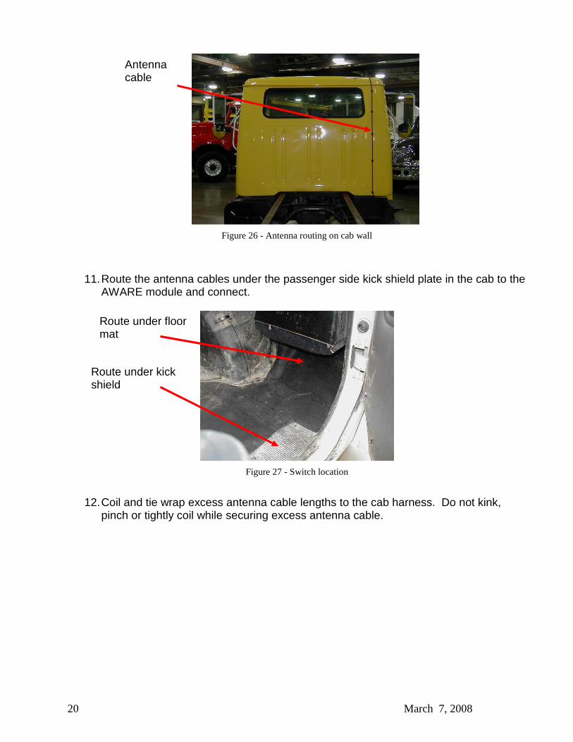
11. Route the antenna cables under the passenger side kick shield plate in the cab to the AWARE module and connect.
Figure 27 - Switch location
12. Coil and tie wrap excess antenna cable lengths to the cab harness. Do not kink,
pinch or tightly coil while securing excess antenna cable.
Antenna cable
Route under floor mat
Route under kick shield
21 March 7, 2008
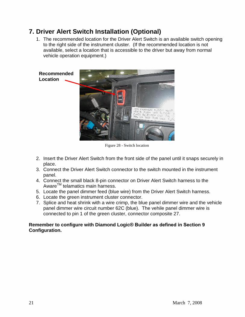
7. Driver Alert Switch Installation (Optional) 1. The recommended location for the Driver Alert Switch is an available switch opening
to the right side of the instrument cluster. (If the recommended location is not available, select a location that is accessible to the driver but away from normal vehicle operation equipment.)
Figure 28 - Switch location
2. Insert the Driver Alert Switch from the front side of the panel until it snaps securely in
place. 3. Connect the Driver Alert Switch connector to the switch mounted in the instrument
panel. 4. Connect the small black 8-pin connector on Driver Alert Switch harness to the
AwareTM telamatics main harness. 5. Locate the panel dimmer feed (blue wire) from the Driver Alert Switch harness. 6. Locate the green instrument cluster connector. 7. Splice and heat shrink with a wire crimp, the blue panel dimmer wire and the vehicle
panel dimmer wire circuit number 62C (blue). The vehile panel dimmer wire is connected to pin 1 of the green cluster, connector composite 27.
Remember to configure with Diamond Logic® Builder as defined in Section 9 Configuration.
Recommended Location
22 March 7, 2008
8. Software Upgrade Verify the module contains the latest version of software by using Diamond Logic® Builder.
Launch Diamond Logic® Builder while connected to the Internet to ensure the latest version
of Diamond Logic® Builder software is downloaded onto the computer:
1. Connect your International ® EZ-Tech® or other laptop with Diamond Logic® Builder to the Internet
2. Launch Diamond Logic® Builder. Once Diamond Logic Builder opens, the computer
may be disconnected from the internet. 3. Turn ignition Key ON. 4. Attach the computer to the diagnostic connector in the vehicle using an EZ-Tech®
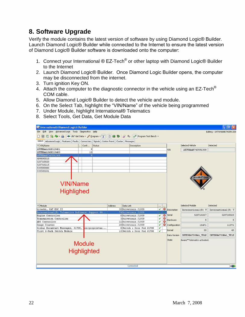
COM cable. 5. Allow Diamond Logic® Builder to detect the vehicle and module. 6. On the Select Tab, highlight the �VIN/Name� of the vehicle being programmed 7. Under Module, highlight International® Telematics 8. Select Tools, Get Data, Get Module Data
23 March 7, 2008
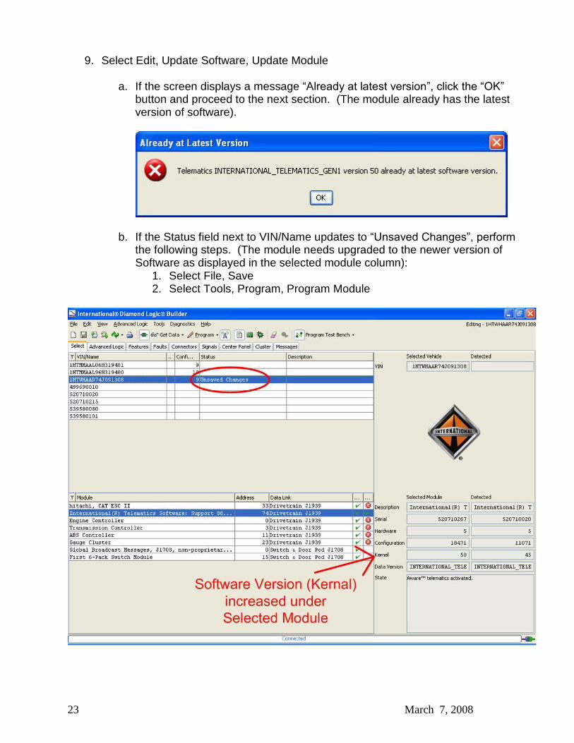
9. Select Edit, Update Software, Update Module
a. If the screen displays a message �Already at latest version�, click the �OK�
button and proceed to the next section. (The module already has the latest version of software).
b. If the Status field next to VIN/Name updates to �Unsaved Changes�, perform
the following steps. (The module needs upgraded to the newer version of Software as displayed in the selected module column):
1. Select File, Save 2. Select Tools, Program, Program Module

24 March 7, 2008
9. Configuration The follow section details how to configure the parameters by using templates. To configure the parameters manually, see Appendix A.
9.1. Download Templates
9.1.1. Dealers Templates can be downloaded from the ISIS web page http://service.navistar.com/ Select menu item: Technical Publications Select menu item: Aware Technical Publication Scroll down on the screen to view the list of templates.
9.1.2. Customers Templates can be downloaded from http://AwareTechPubs.internationaldelivers.com/ Scroll down on the screen to view the list of templates.
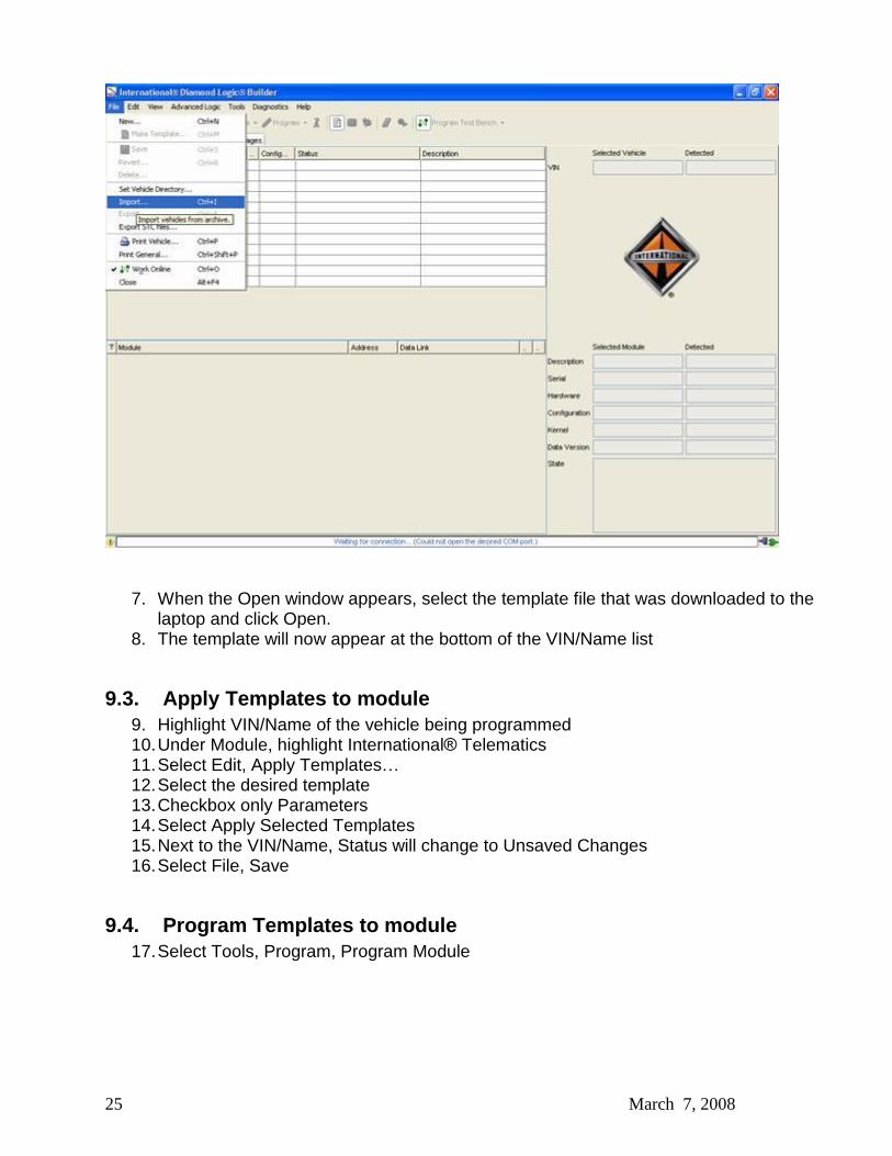
9.2. Import Templates into Diamond Logic® Builder 1. Click on the hyperlink for the applicable template. 2. After the �File Download� screen appears, select Save
3. After the �Save As� screen appears, select a folder you will remember. 4. At the bottom of the �Save As� screen, for �Save as type� select �All Files� 5. Select Save 6. Once the template file finishes downloading, go back to Diamond Logic® Builder, and
select File, Import�
25 March 7, 2008
7. When the Open window appears, select the template file that was downloaded to the laptop and click Open.
8. The template will now appear at the bottom of the VIN/Name list
9.3. Apply Templates to module 9. Highlight VIN/Name of the vehicle being programmed 10. Under Module, highlight International® Telematics 11. Select Edit, Apply Templates� 12. Select the desired template 13. Checkbox only Parameters 14. Select Apply Selected Templates 15. Next to the VIN/Name, Status will change to Unsaved Changes 16. Select File, Save
9.4. Program Templates to module 17. Select Tools, Program, Program Module
26 March 7, 2008
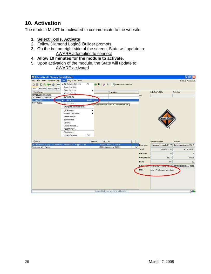
10. Activation The module MUST be activated to communicate to the website.
1. Select Tools, Activate 2. Follow Diamond Logic® Builder prompts. 3. On the bottom right side of the screen, State will update to:
AWARE attempting to connect 4. Allow 10 minutes for the module to activate. 5. Upon activation of the module, the State will update to:
AWARE activated

27 March 7, 2008
11. Final Assembly Steps 1. Locate all remaining blunt cut wires of the AWARE main harness. Wrap the wire
ends in electrical tape to ensure no short circuits. Do not cut or remove the wires. 2. Coil and tie wrap the bundle of wires to the cab harness. 3. Reinstall the instrument cluster. 4. Reinstall passenger side scuff plate cover.
28 March 7, 2008
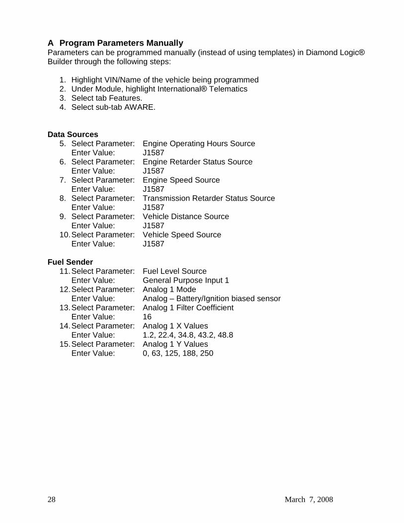
A Program Parameters Manually Parameters can be programmed manually (instead of using templates) in Diamond Logic®
Builder through the following steps:
1. Highlight VIN/Name of the vehicle being programmed 2. Under Module, highlight International® Telematics 3. Select tab Features. 4. Select sub-tab AWARE.
Data Sources
5. Select Parameter: Engine Operating Hours Source Enter Value: J1587
6. Select Parameter: Engine Retarder Status Source Enter Value: J1587
7. Select Parameter: Engine Speed Source Enter Value: J1587
8. Select Parameter: Transmission Retarder Status Source Enter Value: J1587
9. Select Parameter: Vehicle Distance Source Enter Value: J1587
10. Select Parameter: Vehicle Speed Source Enter Value: J1587
Fuel Sender 11. Select Parameter: Fuel Level Source
Enter Value: General Purpose Input 1 12. Select Parameter: Analog 1 Mode
Enter Value: Analog � Battery/Ignition biased sensor 13. Select Parameter: Analog 1 Filter Coefficient
Enter Value: 16 14. Select Parameter: Analog 1 X Values
Enter Value: 1.2, 22.4, 34.8, 43.2, 48.8 15. Select Parameter: Analog 1 Y Values
Enter Value: 0, 63, 125, 188, 250

29 March 7, 2008
Park Brake 16. Select Parameter: Parking Brake Switch Status Source
Enter Value: General Purpose Input 2 17. Select Parameter: Analog 2 Mode
Air Brakes Enter Value: Analog � Vref biased sensor
Hydraulic Brakes Enter Value: Analog � Battery/Ignition biased sensor
18. Select Parameter: Analog 2 X Values Enter Value: 30, 30, 50, 70, 70
19. Select Parameter: Analog 2 Y Values Enter Value: 1, 2, 2, 2, 0
Service Brake 20. Select Parameter: Service Brake Switch Status Source
Enter Value: General Purpose Input 3 21. Select Parameter: Analog 3 Mode
Enter Value: Analog � Battery/Ignition biased sensor 22. Select Parameter: Analog 3 X Values
Enter Value: 30, 30, 50, 70, 70 23. Select Parameter: Analog 3 Y Values
Enter Value: 1, 2, 2, 2, 0 Driver Alert Switch (If the Driver Alert Switch has been installed, perform the next step.)
24. Select Parameter: Driver Alert Switch Installed Enter Value: Enable
25. Select File, Save. 26. Select Edit, Update Software, Update Module to program the module.

30 March 7, 2008
B AWARE Module LED Troubleshooting Table LED�s Indicated Items
A B C D Comments
Power disconnected OFF OFF OFF OFF Sleep mode active Heart-
beat OFF OFF OFF
Awake mode active Slow Flash
- - -
Ignition is ON Steady ON
- - -
Internal Fault Detected Fast Flash
- - - Highest priority for LED �A�. Indicates in Awake
and Ignition modes also. GPS OFF - OFF - - GPS active - Slow
Flash - -
GPS acquired - Steady ON
- -
Cellular Modem OFF - - OFF - Cellular Modem signal strength (Low & no service)
- - Slow Flash
-
Cellular Modem signal strength (High)
- - Steady ON
-
Cellular modem transmitting data
- - Fast Flash
- Highest priority for LED �C�. Shall indicate for a
minimum of 3 seconds. Communication on J1939 data link
- - - Slow Flash
Cellular modem receiving data
- - - Fast Flash
Highest priority for LED �D�. Shall indicate for a minimum of 3 seconds.
Flash Rate Definition
Heartbeat = 1 flash every minute Slow Flash = 1 flash every second Fast Flash = 4 flashes every second