avr7300 sm
TRANSCRIPT
5/13/2018 AVR7300 sm - slidepdf.com
http://slidepdf.com/reader/full/avr7300-sm 1/158
harman/kardon
AVR73007 x 110W 7.1 CHANNEL A/V RECEIVER
SERVICE MANUAL

5/13/2018 AVR7300 sm - slidepdf.com
http://slidepdf.com/reader/full/avr7300-sm 2/158
Some semiconductor (solid state) devices can be damaged easily by static electricity. Such components commonly are called
Electrostatically Sensitive (ES) Devices. Examples of typical ES devices are integrated circuits and some field effect transistors and
semiconductor "chip" components.
The following techniques should be used to help reduce the incidence of component damage caused by static electricity.
1. Immediately before handling any semiconductor component or semiconductor-equipped assembly, drain off any electrostatic charge on
your body by touching a known earth ground. Alternatively, obtain and wear a commercially available discharging wrist strap device,
which should be removed for potential shock reasons prior to applying power to the unit under test.
2. After removing an electrical assembly equipped with ES devices, place the assembly on a conductive surface such as aluminum foil, to
prevent electrostatic charge build-up or exposure of the assembly.
3. Use only a grounded-tip soldering iron to solder or unsolder ES devices.
4. Use only an anti-static solder removal device. Some solder removal devices not classified as "anti-static" can generate electrical charges
sufficient to damage ES devices.
5. Do not use freon-propelled chemicals. These can generate electrical change sufficient to damage ES devices.
6. Do not remove a replacement ES device from its protective package until immediately before you are ready to install it. (Most replacement
ES d i k d ith l d l t i ll h t d t th b d ti f l i f il bl d ti t i l )
AVR7300 harman/kardon

5/13/2018 AVR7300 sm - slidepdf.com
http://slidepdf.com/reader/full/avr7300-sm 3/158
SAFETY PRECAUTIONS
The following check should be performed for the continuedprotection of the customer and service technician.
LEAKAGE CURRENT CHECK
Measure leakage current to a known earth ground (waterpipe, conduit, etc.) by connecting a leakage current testerbetween the earth ground and all exposed metal parts of theappliance (input/output terminals, screwheads, metaloverlays, control shaft, etc.). Plug the AC line cord of theappliance directly into a 120V AC 60Hz outlet and turn theAC power switch on. Any current measured must not exceed
o.5mA.
Device
under test
Test allexposed metalsurfaces
Also test withplug reversed(Using AC adapterplug as required)
Leakagecurrent
tester
Reading shouldnot be above0.5mA
Earthground
AVR7300 harman/kardon
5/13/2018 AVR7300 sm - slidepdf.com
http://slidepdf.com/reader/full/avr7300-sm 4/158
AVR 7300 TECHNICAL SPECIFICATIONS
Audio Section
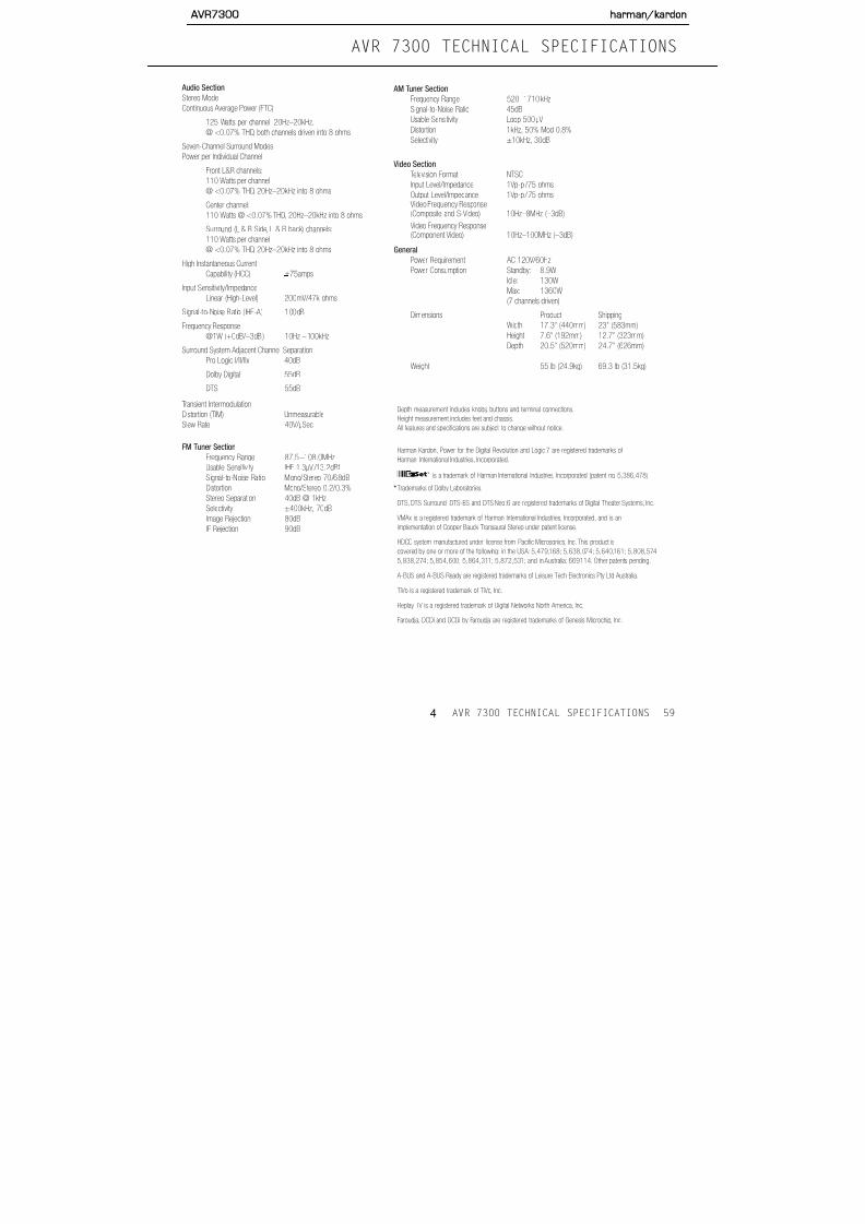
Stereo ModeContinuous Average Power (FTC)
125 Watts per channel, 20Hz–20kHz,
@ <0.07% THD, both channels driven into 8 ohms
Seven-Channel Surround Modes
Power per Individual Channel
Front L&R channels:
110 Watts per channel
@ <0.07% THD, 20Hz–20kHz into 8 ohms
Center channel:
110 Watts @ <0.07% THD, 20Hz–20kHz into 8 ohms
Surround (L & R Side, L & R back) channels:
110 Watts per channel
@ <0.07% THD, 20Hz–20kHz into 8 ohms
High Instantaneous Current
Capability (HCC) +75amps
Input Sensitivity/Impedance
Linear (High-Level) 200mV/47k ohmsSignal-to-Noise Rat io ( IHF-A) 100dB
Frequency Response
@1W (+0dB/–3dB) 10Hz –100kHz
Surround System Adjacent Channel Separation
Pro Logic I/II/IIx 40dB
Dolby Digital 55dB
DTS 55dB
T i t I t d l ti
AM Tuner Section
Frequency Range 520–1710kHzSignal-to-Noise Ratio 45dB
Usable Sensitivity Loop 500µV
Distortion 1kHz, 50% Mod 0.8%
Selectivity ±10kHz, 30dB
Video Section
Television Format NTSC
Input Level/Impedance 1Vp-p /75 ohms
Output Level/Impedance 1Vp-p /75 ohmsVideo Frequency Response(Composite and S-Video) 10Hz–8MHz (–3dB)
Video Frequency Response(Component Video) 10Hz–100MHz (–3dB)
General
Power Requirement AC 120V/60Hz
Power Consumption Standby: 8.9W
Idle: 130W
Max: 1360W
(7 channels driven)
Dimensions Product Shipping
Width 17.3" (440mm) 23" (583mm)
Height 7.6" (192mm) 12.7" (323mm)
Depth 20.5" (520mm) 24.7" (626mm)
Weight 55 lb (24.9kg) 69.3 lb (31.5kg)
AVR7300 harman/kardon

5/13/2018 AVR7300 sm - slidepdf.com
http://slidepdf.com/reader/full/avr7300-sm 5/158
AVR7300 FEATURES
OUTPUT POWER(STEREO) 125W x 2 OUTPUTS
OUTPUT POWER(SURROUND) 110W x 7 Pre-Outs 7.1
20Hz-20kHz, 8 Ohms, 0.07%THD Yes Tape Rear
All Channels Driven Yes Video 1 Rear
High Current Capability Yes Video 2 Rear All-Discrete Amplifier Circuitry Yes Audio/Video Outputs, Switchable Front
Dual Power Supplies, Driver and Output Stages Yes Video Monitor Rear
AUDIO DSP SECTION Digital Outputs (Rear) 1 Coax, 1 Optical
Dolby Digital Yes Digital Outputs (Front) 1 Coax, 1 Optical
Dolby Pro Logic 2 Yes DIGITAL INPUTS
Dolby Digital Ex 6.1 Yes Optical, Rear 3
Dolby Headphone Yes Coax, Rear 3
Dolby Virtualizer Yes Optical, Front 1
DTS, 5.1 Yes Coax, Front 1
DTS, 6.1 Discrete Yes GENERAL FEATURES
DTS NEO 6 Yes On-Screen DisplayComposite, S,
Component
DTS 96/24 Yes Input Titling Yes
VMAx, 2 Modes Near & Far Yes FL Display User ICON
Logic 7, Cinema & Music 5.1, 7.1 Remote In/Out Yes
Logic 7, 5.1 & 7.1 Cinema & Music Yes RS 232 2 Way
HDCD Decoding Yes Port for Flash Upgrade RS 232
MP 3 Decoding Yes A-Buss Ready Yes, 2
5 Channel Stereo Yes IEC Detachable AC Cord Yes
7 Channel Stereo Yes Speaker Binding Posts w/Banana JackCompatibility
Yes
Hall 1 Yes Thermal Controlled Air Cooling
Hall 2 Yes Smart Fan Control System
Theater Yes Multiroom Audio Yes
Quadruple X-Over System Yes Multiroom Video Yes
DVD Audio Bass Management Capability Yes REMOTE CONTROL
Sampling Upconversion to 96kHz Yes # of Devices 8
DSP Processor CS49400 Preprogrammable Yes
D/A Converters 192kHz/24 Bit Yes Learning Yes
Fl h U d bl Y EZ S t Y
AVR7300 harman/kardon

5/13/2018 AVR7300 sm - slidepdf.com
http://slidepdf.com/reader/full/avr7300-sm 6/158
FRONT-PANEL CONTROLSFRONT-PANEL CONTROLS
1 2
)$ #^ @ !%
3 4 5 6 7 8
1 2 5
6
73
4
9
8 13
1410
11
12
15
9
AVR7300 harman/kardon

5/13/2018 AVR7300 sm - slidepdf.com
http://slidepdf.com/reader/full/avr7300-sm 7/158
FRONT-PANEL CONTROLS
1 Standby/On Button: When the Main Power
Switch is pressed in so that it is in the “ON”position, press this button to turn on the AVR 7300.
When the unit is in the Standby mode, the switch is
surrounded by amber lighting. When the unit is on,
the lighting around the button is blue.
2 Surround Mode Group Selector: Press this but-
ton to select the top-level group of surround modes.
Each press of the button will select one of the sur-
round mode categories. Once the button is pressed so
that the name of the desired surround mode category
appears in the on-screen display and in the Lower
Display Line $, press the Surround Mode
Selector 3 to cycle through the individual modes
available. For example, press this button to select
Dolby modes, and then press the Surround Mode
Selector 3 to choose from the various mode
options.
3 Surround Mode Selector: Press this button
to select from among the available surround mode
options for the surround mode category selected.
The specific modes will vary based on the number of
speakers available, the surround mode category and
whether the input source is digital or analog. For
example, press the Surround Mode Group Selector
2 to select a category such as Dolby or Logic 7,
and then press this button to see the specific mode
choices that are available. For more information on
mode selection, see page 35.
4 T i S l P h l f id f h b
5 Tuner Band Selector: Pressing this button will
switch to the Tuner mode. Pressing it again will switchbetween the AM and FM frequency bands. (See page
39 for more information on the tuner.)
6 Preset Stations Selector: Press this button to
scroll up or down through the list of stations that have
been entered into the preset memory. (See page 39
for more information on tuner programming.)
7 Input Source Selector: Press this button to
change the input by scrolling up or down through the
list of input sources.
8 Tuner Mode Selector: Press this button to select
Auto or Manual tuning.When the button is pressed so
that AUTO/STEREO appears in the Upper
Display Line #, the tuner will search for the next
station with an acceptable signal when the Tuning
Selector 5wé is pressed.When the button
is pressed so that MANUAL/MONO appears
in the Upper Display Line #, each press of the
Tuning Selector 5wé will increase the fre-quency. (See page 39 for more information on using
the tuner.) This button may also be used to switch
between Stereo and Mono modes for FM radio recep-
tion. When weak reception is encountered, select the
MANUAL/MONO tuning mode. Press and hold
again to switch back to AUTO/STEREO
mode. (See page 39 for more information on using
the tuner.)
9 Front-Panel Control Door: To open the door so
tor when a “small” speaker is selected and as a larger
icon with three connected boxes when “large” speak-ers are selected. When only the speaker position let-
ters appear, no speaker has been assigned to that
position. (See page 26 for more information on con-
figuring speakers.) The letters inside each box also
indicate the active input channels. For standard analog
inputs, only the L and R will light, indicating a stereo
input. For a digital source, the indicators will light to
display the channels being received at the digital input.
When the letters flash, the digital input has been inter-
rupted and an UNLOCK message may appear inthe Lower Display Line $. (See page 38 for more
information on the Channel Indicators.)
# Upper Display Line: Depending on the unit’s
status, a variety of messages will appear here. In
normal operation, this line will show the current input
source and identify whether an analog or digital input
is in use. When the tuner is selected as the input, this
line will identify the station as AM or FM and show the
frequency and preset number, if any.$ Lower Display Line: Depending on the unit’s
status, a variety of messages will appear here. In nor-
mal operation, the current surround mode will appear
on this line.
% Surround Mode Indicators: One of these
indicators will light to show the surround mode in
use. Depending on the specific combination of input
sources and surround mode selected, more than
i di li h (S 3 f
1
AVR7300 harman/kardon
5/13/2018 AVR7300 sm - slidepdf.com
http://slidepdf.com/reader/full/avr7300-sm 8/158
FRONT-PANEL CONTROLS
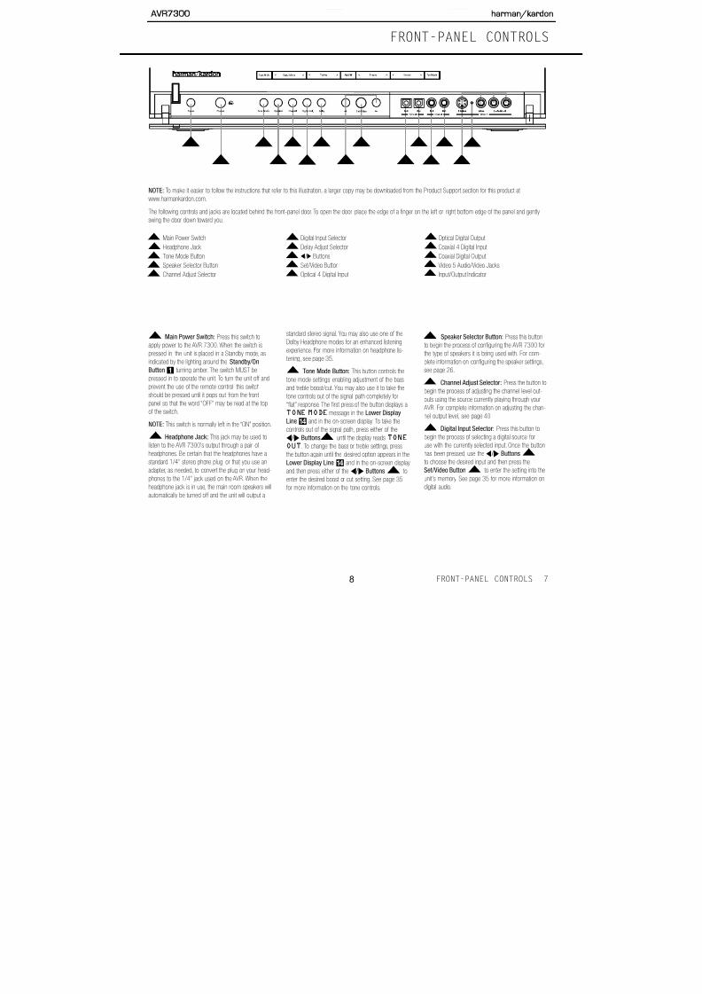
NOTE: To make it easier to follow the instructions that refer to this illustration, a larger copy may be downloaded from the Product Support section for this product at
www.harmankardon.com.
The following controls and jacks are located behind the front-panel door. To open the door, place the edge of a finger on the left or right bottom edge of the panel and gently
swing the door down toward you.
1
2
5
6
73
4
9
8
13
1410
11
12
15
Main Power Switch
Headphone Jack
Tone Mode Button
Speaker Selector Button
Channel Adjust Selector
Digital Input Selector
Delay Adjust Selector
‹ / › Buttons
Set/Video Button
Optical 4 Digital Input
Optical Digital Output
Coaxial 4 Digital Input
Coaxial Digital Output
Video 5 Audio/Video Jacks
Input/Output Indicator
1
2
3
4
5
6
7
8
9
10
11
12
13
14
15
AVR7300 harman/kardon

5/13/2018 AVR7300 sm - slidepdf.com
http://slidepdf.com/reader/full/avr7300-sm 9/158
FRONT-PANEL CONTROLS
Delay Adjust Selector: Press this button to
begin the process of adjusting the delay settings. Seepage 28 for more information on delay adjustments.
‹ / › Buttons: When making system configu-
ration changes using the front-panel controls, press
these buttons to scroll through the available choices
for the option being adjusted.
Set/Video Button: This button has two func-
tions. Press it to turn the video processing circuits on
or off, as indicated by FAROUDJA:ON or
FAROUDJA:OFF messages in the Lower
Display Line $ and semi-OSD display. (See page
31 for more information on the video processing cir-
cuits.) The button is also used when making many of
the configuration and setup adjustments from the front
panel. When selecting a specific item to adjust, or after
selecting a configuration setting with the ‹ / › Buttons
, press this button to enter the setting informa-
tion to the unit’s memory.
Optical 4 Digital Input: Connect the opticaldigital output of an audio or video product to this jack.
Optical Digital Output: Connect this jack
to the optical digital audio input of a compatible
digital recorder.
Coaxial 4 Digital Input: Connect the coaxial
digital output of a digital audio product such as aportable audio player or video game to this jack.
Coaxial Digital Output: Connect this jack to
the digital audio input of a compatible digital recorder.
Video 5 Input/Output Jacks: These
audio/video jacks may be used as either inputs or
outputs for temporary connection to video games or
portable audio/video products such as camcorders
and portable audio players. (See page 40 for more
information on switching these jacks between an
input and output.)
Input/Output Status Indicator: This LED indi-
cator will normally light green to show that the front-
panel Video 5 Input/Output Jacks is operat-
ing as an input. When this jack is configured for use
as an output, the appropriate indicator will turn red to
show that the jack may be used as an output for
recording. (See page 23 for more information on
configuring the front-panel jacks as outputs, ratherthan inputs.)
14
15
14
13
12
11
10
8
9
8
7
AVR7300 harman/kardon

5/13/2018 AVR7300 sm - slidepdf.com
http://slidepdf.com/reader/full/avr7300-sm 10/158
REAR-PANEL AUDIO CONNECTIONS
ø
√ ü ß ® œ πå ∫
å
∫
ç
ç∂
é
ƒ
©
˙
î
∆
˚
¬
µ
ñ
†
AVR7300 harman/kardon

5/13/2018 AVR7300 sm - slidepdf.com
http://slidepdf.com/reader/full/avr7300-sm 11/158
REAR-PANEL AUDIO CONNECTIONS
å Front Speaker Outputs: Connect these outputs
to the matching + or – terminals on your left and right speakers.When making speaker connections, always
make certain to maintain correct polarity by connecting the
color-coded (white for front left and red for front right) (+)
terminals on the AVR7300 to the red (+) terminals on the
speakers and the black (–) terminals on the AVR 7300 to
the black (–) terminals on the speakers.See page 18 for
more information on speaker polarity.
∫ Surround Speaker Outputs: Connect these outputs
to the matching + and – terminals on your surround
channel speakers. In conformance with the CEA color-
code specification, the blue terminal is the positive (+)
terminal that should be connected to the red (+) terminal
on the Surround Left speaker with older color-coding,
while the gray terminal should be connected to the red (+)
terminal on the Surround Right speaker with the older
color-coding. Connect the black (–) terminal on the AVR to
the matching black negative (–) terminals for each sur-
round speaker. (See page 18 for more information on
speaker polarity.
ç Surround Back/Multiroom Speaker Outputs:
These speaker terminals are normally used to power the
surround back left/surround back right speakers in a 7.1-
channel system. However, they may also be used to
power the speakers in a second zone, which will receive
the output selected for a multiroom system. To change the
output fed to these terminals from the default of the
Surround Back speakers to the Multiroom Output, you
MULTI-ROOM
jacks are used to connect a DVD player, the AVR may be
reconfigured to accommodate the hookup by using theIN/OUTSETUPmenu as shown on page 23.
Video 4 Audio Inputs: Connect the left/right
analog audio outputs of a video device to these jacks.
The AVR 7300’s remote control has a satellite receiver as
the default for this input, but you may connect any video
source such as a VCR, HDTV receiver, personal video
recorder, or other device to these inputs.Note that if the
source device offers either digital audio or component
video capability, those connections must be made sepa-
rately, and the AVR 7300 configured accordingly. (See
page 23 for more information on configuring an input for
various source options.)
î Video 3 Audio Inputs: Connect the left/right
analog audio outputs of a video device to these jacks.
The AVR7300’s remote control has a cable set-top as
the default for this input, but you may connect any video
source such as a VCR, HDTV or satellite receiver, personal
video recorder, or other device to these inputs.Note that if
the source device offers either digital audio or component
video capability, those connections must be made sepa-
rately, and the AVR 7300 configured accordingly. (See
page 23 for more information on configuring an input for
various source options.)
∆ Video 2 Audio Outputs: Connect the left/right analog
audio RECORD/IN jacks of a video recording device such
as a VCR, DVD-recorder or personal video recorder to
these jacks.
ø Multiroom Audio Outputs: Connect these jacks to
the optional external audio power amplifier that delivers thesource selected for multizone distribution.
π Video 1 Audio Outputs: Connect the left/right analog
audio RECORD/IN jacks of a video recording device such
as a VCR, DVD-recorder or personal video recorder to
these jacks.The AVR 7300’s remote control has a VCR as
the default for this input, but you may connect any video
source such as a VCR, HDTV or cable set-top box, per-
sonal video recorder, or other device to these inputs.Note
that if the source device offers either digital audio or com-
ponent video capability, those connections must be made
separately, and the AVR 7300 configured accordingly.
(See page 23 for more information on configuring an input
for various source options.)
œ Optical Digital Audio Output: Connect this jack to
the optical digital input connector on a CD-R/RW, MiniDisc
or other compatible digital recorder.
® Optical Digital Audio Inputs: Connect the optical
digital output from a DVD player, HDTV receiver, theS/P-DIF output of a compatible computer sound card
playing MP3 files or streams, LD player or CD player to
these jacks.The signal may be a Dolby Digital signal,
a DTS signal or a standard PCM digital source.
ß Coaxial Digital Audio Output: Connect this jack to
the coaxial digital input of a CD-R/RW, MiniDisc or other
compatible digital recorder.
AVR7300 harman/kardon

5/13/2018 AVR7300 sm - slidepdf.com
http://slidepdf.com/reader/full/avr7300-sm 12/158
VIDEO AND SYSTEM CONNECTIONS
O
VU S
R
Q
P
WX
A
B
C
D
E
F
G
H
I
J
K
L
M
N
T
AVR7300 harman/kardon

5/13/2018 AVR7300 sm - slidepdf.com
http://slidepdf.com/reader/full/avr7300-sm 13/158
VIDEO AND SYSTEM CONNECTIONS
A Amp Trigger: Connect this jack to the “Trigger In”
jack of an optional, external power amplifier that isequipped for remote turn-on via a 6-volt signal.When
this connection is used, the AVR 7300 will automatically
send a low-voltage signal that turns on the amp when the
AVR is on, and since the signal is not present when the
AVR is turned off, the amplifier will also turn off with the
AVR 7300.
B Multiroom IR Input: Connect the output of an IR
sensor in a remote room to this jack to operate the
AVR’s multiroom control system.
C Remote IR Output: This connection permits the
IR sensor in the receiver to serve other remote-con-
trolled devices. Connect this jack to the “IR IN” jack on
Harman Kardon (or other compatible) equipment.
D Remote IR Input: If the AVR 7300’s front-panel
IR sensor is blocked due to cabinet doors or other
obstructions, an external IR sensor may be used.
Connect the output of the sensor to this jack.
E Component Video Monitor Outputs: Connect
these outputs to the component video inputs of a
video projector or monitor. When a source connected
to one of the Component Video Inputs FGH is
selected, the signal will be sent to these jacks.
F DVD Component Video Inputs: Connect the
component video outputs of a DVD player or any
other video source equipped with Y/Pr/Pb or RGB
I DVD Video Inputs: The default use for these
inputs is the connection to the composite and/or S-Video output of a DVD player, but they may be used
with a different video source if desired.
J Video Monitor Outputs: When using an analog
video display that has only standard composite and
S-Video inputs, connect the output of these jacks
(depending on which types of video are used by your
source devices) to the matching inputs on your televi-
sion or video display. When using a “digital ready” or
HDTV display that is compatible with 480P or higher
inputs, you do not need to make these connections as
all incoming video will be up-scaled to 480P and sent
through the Component Video Monitor Jacks Ewith the OSD messages.
K Video 4 Video Inputs: Connect the composite or
S-Video jacks of a video device to these jacks. The
AVR 7300’s remote control has a satellite receiver as
the default for this input, but you may connect any
video source such as a VCR, HDTV receiver, personal
video recorder, or other device to these inputs. (See
page 23 for more information on configuring an input
for various source options.)
L A-BUS Connectors: Connect these jacks to an
optional A-BUS®-certified remote modules to extend the
multiroom capabilities of your AVR 7300. See page 20
for more information on A-BUS.
M Video 1 Video Outputs: Connect the composite
will remain available at this outlet as long as the
AVR 7300 is plugged into an AC power source,
regardless of whether the AVR itself is on or off.
R Switched AC Outlets: These outlets may be used
to power AC devices that you wish to have turn on
and off when the AVR is turned on or off. The total
power consumption of all devices connected to the
two outlets may not exceed 100 watts.
S RS-232 Port: This jack may be used to control
the AVR 7300 over a bi-directional RS-232 serial
control link to a compatible computer or programmableremote control system. Due to the complexity of
programming RS-232 commands, we strongly
recommend that connections to this port for control
purposes be made by a trained and qualified
technician. This jack may also link to a compatible
computer to upgrade the software and operating sys-
tem of the AVR 7300 when appropriate upgrades are
available.
T Video 2 Video Inputs: Connect the composite or S-Video PLAY/OUT jacks of a video recording device such
as a VCR, DVD-recorder or personal video recorder to
these jacks. The AVR 7300’s remote control has a VCR
as the default for this input, but you may connect any
video source such as a VCR, HDTV or cable set-top box,
personal video recorder, or other device to these inputs.
(See page 23 for more information on configuring an
input for various source options.)
AVR7300 harman/kardon

5/13/2018 AVR7300 sm - slidepdf.com
http://slidepdf.com/reader/full/avr7300-sm 14/158
MAIN REMOTE CONTROL FUNCTIONS
0 Power Off Button
1 Power On Button
2 LCD Information Display
3 Input Selectors
4 AVR Selector
5 DSP Surround Mode Selector
6 Test Button
7 Video Processing On/Off Button
8 Direct Button
9 Clear Button
A Numeric Keys
B Tuning Mode Buttonm Dim Button
n Channel Select Button
o Navigation Button
F Digital Select Button
G Set Button
H Volume Up/Down Buttons
I Transport Fast-Play/Scan Buttons
J Main Transport Controls
K Track Skip Up/Down Buttons
L Preset Up/Down ButtonM Tuning Up/Down Button
N Disc Skip Button
O Program Button
P Light ButtonQ Multiroom Button
R Macro Buttons
S Sleep Button
T Night Mode Button
U OSD Button
VIDEO
1
2
3
456
7
9
i
j
kl
A
D
F
0
C
a
b
d8
B
ef
h
c
E
g
AVR7300 harman/kardon

5/13/2018 AVR7300 sm - slidepdf.com
http://slidepdf.com/reader/full/avr7300-sm 15/158
MAIN REMOTE CONTROL FUNCTIONS
IMPORTANT NOTE: The AVR 7300’s remote may
be programmed to control up to nine devices,
including the AVR 7300. Before using the remote,
it is important to remember to press the Input
Selector Button3 that corresponds to the unit
you wish to operate. In addition, the AVR 7300’s
remote is shipped from the factory to operate the
AVR 7300 and most Harman Kardon CD or DVD
players and cassette decks. The remote is also
capable of operating a wide variety of other products
using the control codes that are part of the remote.
Before using the remote with other products, followthe instructions on pages 46 – 55 to program the
proper codes for the products in your system.
It is also important to remember that many of the
buttons on the remote take on different functions,
depending on the product selected using the Input
Selectors d. The descriptions shown here primarily
detail the functions of the remote when it is used to
operate the AVR 7300.
a Power Off Button: Press this button to placethe AVR 7300 or a selected device in the Standby
mode. Note that this will turn off the main room
functions, but if the Multiroom system is activated,
it will continue to function.
1 Power On Button: Press this button to turn on
the power to a device selected by first pressing one of
the Input Selectors3.
2 LCD Information Display: This two-line screen
g Test Button: Press this button to begin the
sequence used to calibrate the AVR 7300’s output levels. (See page 29 for more information on calibrat-
ing the AVR 7300.)
h Video Processing On/Off Button: Press this
button to turn the video processing circuits on or off.
See page 31 for more information.
8 Direct Button: Press this button when the tuner
is in use to start the sequence for direct entry of a
station’s frequency. After pressing the button, simply
press the proper Numeric KeysA to select astation. (See page 39 for more information on the tuner.)
9 Clear Button: When programming the remote
or using the EzSet feature, press this button to cancel
the current function.When using the remote to enter
frequencies for direct tuner access, press this button
to clear previous entries.
A Numeric Keys: These buttons serve as a 10-
button numeric keypad to enter tuner preset positions.
They are also used to select channel numbers whenTV, Cable or SAT has been selected on the remote, or
to select track numbers on a CD, DVD or LD player,
depending on how the remote has been programmed.
These buttons are also used to enter letters and num-
bers when renaming devices in the LCD Information
Display. (See page 53 for more information on renam-
ing devices and keys.)
B Tuning Mode Button: Press this button to
m Dim Button: This button activates the Dimmer
function, which reduces the brightness of the front-panel display, or turns it off entirely. Press the button
once to reduce the display brightness by 50%, and
press it again within five seconds and the main display
will go completely dark. Note that this setting is tem-
porary; regardless of any changes, the display will
always return to full brightness when the AVR is turned
on. The blue accent lighting inside the Volume
Control ) and the Input/Output Indicator
will go out when the panel lights are at half brightness
or fully dimmed.
n Channel Select Button: This button is used to
start the process of setting the AVR 7300’s output levels
to an external source. Once this button is pressed, press
the ⁄ / ¤ on the Navigation Button o to select the
channel being adjusted, then press the Set Buttonq,
followed by the ⁄ / ¤ on the Navigation Buttonoagain, to change the level setting. (See page 40 for more
information.)
o Navigation Button: This single disc-like button isused to navigate through the on-screen configuration
menus, to scroll through the options list and to select
choices for the various settings such as delay, speakers,
surround modes, digital inputs, etc. To use the button,
simply press it left, right, up or down in the direction
indicated by the ⁄ / ¤ / ‹ / › icons printed on the but-
ton disc. Depending on the menu being used, press-
ing the button will either change a specific menu or
configuration choice or change the option shown in
15
MAIN REMOTE CONTROL FUNCTIONS
AVR7300 harman/kardon

5/13/2018 AVR7300 sm - slidepdf.com
http://slidepdf.com/reader/full/avr7300-sm 16/158
MAIN REMOTE CONTROL FUNCTIONSMAIN REMOTE CONTROL FUNCTIONS
s Transport Fast-Play/Scan Buttons: These but-
tons have no direct function on the AVR 7300, but
they are used when the remote is programmed for a
compatible DVD, CD or tape player. Pressing these but-
tons will transmit a fast-play forward, fast-play reverse,
or fast-forward or fast-reverse scan command, accord-
ing to the capabilities of the player being controlled. In
the factory default setting, these buttons are prepro-
grammed with the remote codes for Harman Kardon
DVD players so that you may control a compatible
player even when the remote is directly controlling the
AVR, a TV set, or a cable or satellite set-top box.J Main Transport Controls: These buttons have
no direct function on the AVR 7300 but are used
when the remote is programmed for a compatible
DVD, CD or tape player. Pressing these buttons
will transmit a stop (Í), record (Î), or pause (±)
command, according to the capabilities of the player
being controlled. In the factory default setting, these
buttons are programmed with the remote codes for
Harman Kardon DVD players so that you may control
a compatible player even when the remote is directly
controlling the AVR, a TV set, or a cable or satellite
set-top box.
K Track Skip Up/Down Buttons: These buttons
do not have a direct function with the AVR 7300, but
when used with a compatibly programmed CD or DVD
changer will change the track or chapter currently being
played. In the factory default setting, these buttons are
programmed with the remote codes for Harman Kardon
once, and the tuner will scan for a station with accept-
able signal strength. When the next higher- or lower-
frequency station with a strong-enough signal is tuned,
the frequency scan will stop and the Lower Display
Line $ and the on-screen display will indicate
AUTO TUNED. When an FM Stereo station is
tuned, the display will read AUTOSTTUNED.
See page 35 for more information on using the tuner.
N Disc Skip Button: This button has no direct
function for the AVR 7300 but may be used to
change the disc in a CD or DVD changer when the
remote is programmed for that type of device.
O Program Button: This button is used to begin
the process of programming the remote. Press and hold
this button for three seconds to place the remote in the
programming mode.Once the red LED under the Set
Buttonq lights, release the button. You may then
select from the desired option. (See pages 46 – 55 for
more information on configuring the remote.)
P Light Button: Press this button to activate the
remote’s backlight for ease of use in darkened rooms.
QMultiroom Button: Press this button to begin
the process of activating the multiroom system or to
change the input or volume level for the second zone.
(See page 44 for more information on the multiroom
system.)
R Macro Buttons: Press these buttons to store or
recall a “Macro”, which is a preprogrammed sequence
of commands stored in the remote. (See page 49 for
U OSD Button: Press this button to activate or turn
off the On-Screen Display (OSD) system used to set up
or adjust the AVR 7300’s parameters.
V Tone Control Button: This button controls the
tone mode settings, enabling adjustment of the bass
and treble boost/cut. You may also use it to take the
tone controls out of the signal path completely for
“flat” response. The first press of the button displays a
TONEIN message in the Lower Display Line
$ and in the on-screen display.To take the controls
out of the signal path, press either of the ⁄ / ¤
Navigation Buttons o until the display readsTONEOUT. To change the bass or treble settings,
press the button again until the desired option appears
in the Lower Display Line $ and on-screen display
and then press either of the ⁄ / ¤ Navigation
Buttons o to enter the desired boost or cut
setting. See page 35 for more information on the
tone controls.
W Mute Button: Press this button to momentarily
silence the AVR 7300 or TV set being controlled,depending on which device has been selected.
X AM/FM Button: Press this button to select the
AVR 7300’s tuner as the listening choice. Pressing this
button when the tuner is already in use will select
between the AM and FM bands.
Y Channel Up/Down Selector: These selectors
share the disc in the lower portion of the remote with
the Volume Up/Down ButtonsH. They have no
AVR7300 harman/kardon

5/13/2018 AVR7300 sm - slidepdf.com
http://slidepdf.com/reader/full/avr7300-sm 17/158
MAIN REMOTE CONTROL FUNCTIONS
a Delay Select Button: This button selects
adjustments to the A/V Sync Delay and the individual
channel delays. The first press of the button displays
an A/V SYNCDELAY message in the Lower
Display Line $ and in the on-screen display, which
means that you may change the amount of time that
all channels are delayed together behind the video.
This enables you to compensate for the loss of lip
sync that may be caused by digital video processing
in your display or by television stations. To change
the A/V Sync Delay, press the Set Button q while
theA/V SYNCDELAY
message is visibleand then use the ⁄ / ¤ Navigation Button oto change the setting so that the sound and the
video image are in sync. To change the delay for
an individual output channel, press the ⁄ / ¤
Navigation Button o until the desired channel
name is shown, and then press the Set Button q.
Use the ⁄ / ¤ Navigation Buttons o to change
the delay amount. (See page 28 for more information
on delay options.)
b Speaker Select Button: Press this buttonto begin the process of configuring the AVR 7300’s
bass management system. Then press the ⁄ / ¤
Navigation Button o to select the channel you
wish to set up. Press the Set Button q and
then select another channel to configure. When all
adjustments have been completed, press the Set
Button q twice to exit the settings and return to
normal operation. (See page 26 for more information
on speaker setup.)
left/right stereo mode with no surround processing or
bass management, as opposed to other modes where
digital processing is used. When the button is pressed
so that SURROUND OFF appears in the Lower
Display Line$, and theDSP and SURROUND
OFF Surround Mode Indicators % are lit, you will
enjoy a two-channel presentation of the sound along
with the benefits of bass management. Depending on
whether your system is configured for 5.1 or 6.1/7.1
channels, the next press of the button will cause either
5 CHSTEREO or 7 CHSTEREO to
appear, and the stereo signal will be routed to all five(or seven) speakers. (See page 36 for more informa-
tion on stereo playback modes.)
e DTS Neo:6 Mode Select Button: Press this
button as needed to select one of the DTS Neo:6
modes. (See page 36 for the available DTS Neo:6
options.)
f Logic 7 Mode Select Button: Press this button
to select from among the available Logic 7 surround
modes. (See page 36 for the available Logic 7 options.)
g DTS Digital Mode Select Button: When a
DTS-encoded digital source is playing, each press of
this button will scroll through the available DTS modes.
The specific choice of modes will vary according to
the type of encoding on the disc and your system’s
speaker configuration.When a DTS source is not in
use, this button has no function. (See page 36 for the
available DTS digital options.)
pressed, you will then need to select between auto-
matic EzSet operation or using the remote as a manu-
al SPL meter by pressing the ⁄ / ¤ Navigation
Button o until your choice appears in the remote’s
LCD display. Press the Set Button q to enter the
setting, and then follow the instructions as displayed
in the LCD display. (For complete information, see
page 29.)
k EzSet Microphone Sensor: The microphone
sensor that is used by the EzSet system is behind the
three slots at the top of the remote control. When
using EzSet to calibrate the AVR 7300, be certain that the slots are not covered. (See page 29 for more
information on using EzSet.)
l Lens: The infrared emitters behind the plastic
lens at the top of the remote communicate the remote
codes to the AVR 7300. Be certain that the lens is not
covered when using the remote, and point the lens
toward the AVR for best results. In learning mode, the
remote receives IR codes to be learned through a
sensor behind the lens.
NOTE: DO NOT remove the rubber plug that is supplied
to cover the jack on the upper right side of the remote.
The jack is not active and is reserved for future use.
AVR7300 harman/kardon

5/13/2018 AVR7300 sm - slidepdf.com
http://slidepdf.com/reader/full/avr7300-sm 18/158
INSTALLATION AND CONNECTIONS
System Installation
After unpacking the unit, locating it in a place with ade-
quate ventilation and placing it on a solid surface capable
of supporting its weight, you will need to make the con-
nections to your audio and video equipment.
IMPORTANT NOTE: For your personal safety and to
avoid possible damage to your equipment and speakers,
it is always a good practice to turn off and unplug the
AVR and ALL source equipment from the AC output
before making any audio or video system connections.
Audio Equipment Connections
We recommend that you use high-quality interconnect
cables when making connections to source equipment
and recorders to preserve the integrity of the signals.
1. Connect the analog output of a CD player to the
CD Inputs ƒ.
NOTE: If your CD player has both fixed and variable
audio outputs, it is best to use the fixed output unless
you find that the input to the receiver is so low that the
sound is noisy, or so high that it is distorted.
2. Connect the analog Play/Out jacks of a cassette
deck, MD, CD-R or other audio recorder to the
Tape Inputs É. Connect the analog Record/In
jacks on the recorder to the Tape Outputs ∂on the AVR 7300.
3. Connect the output of any digital audio source
300-ohm twin-lead cable, you must use an optional
300-ohm-to-75-ohm adapter to make the
connection.
7. Connect the front, center, surround and surround
back speaker outputs å∫ç√ to the respec-
tive speakers.
To ensure that all the audio signals are carried to your
speakers without loss of clarity or resolution, we sug-
gest that you use high-quality speaker cable. Many
brands of cable are available and the choice of cable
may be influenced by the distance between yourspeakers and the receiver, the type of speakers you
use, personal preferences and other factors. Your
dealer or installer is a valuable resource to consult in
selecting the proper cable.
Regardless of the brand of cable selected, we recom-
mend that you use cable with a gauge of 14 or smaller.
Remember that in specifying cable, the lower the
number, the thicker the cable.
Cable with a gauge of 16 may be used for short runs
of less than 10 feet. We do not recommend that you
use cables with an AWG equivalent of 18 or higher,
due to the power loss and degradation in performance
that will occur.
Cables that are run inside walls should have the appro-
priate markings to indicate listing with UL, CSA or other
appropriate testing agency standards. Questions about
running cables inside walls should be referred to your
round-right speakers, even if the speakers are a
different distance from the AVR 7300.
8. Connections to a subwoofer are normally made via
a line-level audio connection from the Subwoofer
Output µ to the line-level input of a subwoofer
with a built-in amplifier. When a passive subwoofer
is used, the connection first goes to a power ampli-
fier, which will be connected to one or more sub-
woofer speakers. If you are using a powered sub-
woofer that does not have line-level input connec-
tions, follow the instructions furnished with the
speaker for connection information.
9. If an external multichannel audio source with 5.1
outputs such as an external digital processor/
decoder, DVD-Audio or SACD player is used,
connect the outputs of that device to the
8-Channel Direct Inputs Ü.
Video Equipment Connections
Video equipment is connected in the same manner
as audio components. Again, the use of high-qualityinterconnect cables is recommended to preserve
signal quali ty.
1. Connect the analog left/right audio and composite
video or S-Video Play/Out jack of a VCR, personal
video receiver (PVR) or DVD-recorder to the
Video 1 or Video 2 Audio and Video Input
Jacks ñ˚NT on the rear panel. We recom-
mend that VCRs and PVRs be connected to the
AVR7300 harman/kardon

5/13/2018 AVR7300 sm - slidepdf.com
http://slidepdf.com/reader/full/avr7300-sm 19/158
INSTALLATION AND CONNECTIONS
on page 48. You may also “learn” the codes for most
remotes to any input button on the remote by follow-
ing the instructions for “Learning Commands” as
shown on page 47.
4. Connect the analog left/right audio and composite
video or S-Video and analog left/right audio outputs
of a DVD player to the DVD Audio and Video
Input Jacks ©I on the rear panel.
5. Connect the optical or coaxial digital audio outputs
of a DVD player, satellite receiver, cable box, HDTV
tuner or video game to any of the Optical orCoaxial Digital Inputs ®† . The
recommended connection for a DVD player is to
use a coaxial digital link connected to the Coaxial
Digital Audio Input 1, but you may change the
digital audio input assignment for any source using
the IN/OUTSETUP menu, as described
on page 23, or the Digital Input Selector
p on the front panel or remote, as described on
page 37.
NOTE: When connecting a device such as a digital
cable box or other set-top tuner product with a digital
audio output, we recommend that you connect both
the digital and analog outputs of the product to your
AVR. The audio input polling feature of the AVR will
then be able to make certain that you have a constant
audio feed, since it will automatically switch the audio
input to the analog jacks if the digital feed is interrupted
or not available for a particular channel.
the component video inputs of your TV, projector
or other display device.
9. If you have a camcorder, video game or other
audio/video device that is connected to the AVR
on a temporary, rather than permanent, basis,
connect the audio, video and digital audio outputs
of that device to the Front-Panel Inputs
. A device connected here is
selected as the Video 5 input, and the digital
inputs must be assigned to the Video 5 input.
(See page 23 for more information on input
configuration.)
10. When connecting the AVR 7300 to a “digital ready”,
“HDTV compatible” or high-definition display (which
is any device capable of accepting an input signal of
480P or higher), you are able to take advantage of
the unit’s advanced video processing circuitry which
converts all video signals to a 480P output. Since
the AVR 7300 displays the on-screen menus
with upconverted video, the connection from the
AVR 7300 to the display need only be one set of Y/Pr/Pb component video cables to the
Component Video Monitor Output E.
11. When connecting the AVR 7300 to a standard,
analog video display that has standard composite
and S-Video inputs only, component video inputs
may not be used. In this case, connect the Video
Monitor Output J to the matching composite
and S-Video inputs on your video display, depend-
If other components are also prevented from receiving
remote commands, only one sensor is needed. Simply
use this unit’s sensor or a remote eye by running a
connection from the Remote IR Output C jack to
the Remote IR Input jack on Harman Kardon (or other
compatible) equipment.
Multiroom IR Link
The remote room IR receiver should be connected to
the Multiroom IR Input B jack on the AVR 7300’s
rear panel.
If other Harman Kardon-compatible source equipment is part of the main room installation, the Remote IR
Output C jack on the rear panel should be connected
to the IR IN jack on source equipment. This will enable
the remote room location to control source equipment
functions.
NOTE: All remotely controlled components must be
linked together in a “daisy chain.” Connect the IR OUT
jack of one unit to the IR IN of the next to establish
this chain.
Multiroom Connections
The AVR 7300 is equipped with multizone capabilities
that allow it to send an audio and/or video source to a
remote zone that is different from the one selected for
use in the main room. Please note that this capability
applies to analog inputs from sources such as the
AVR’s tuner, tape decks or VCRs. If you wish to use a
source such as a DVD or CD player that is normally
1412
10
6
1210
AVR7300 harman/kardon

5/13/2018 AVR7300 sm - slidepdf.com
http://slidepdf.com/reader/full/avr7300-sm 20/158
INSTALLATION AND CONNECTIONS
use the full 7.1-channel capabilities of the AVR 7300
in the main listening room, but you will be able to
add another listening room without external power
amplifiers. To use the internal amplifiers to power a
remote zone, connect the speakers for the remote
room location to the Surround Back/Multiroom
Speaker Outputs ç. Before using the remote
room, you will need to configure the amplifiers
for surround operation by changing a setting
(following the instructions shown on page 44) in
the MULTI-ROOMSETUP menu.
NOTE: For all options, you may connect an optional
IR sensor in the remote room to the AVR 7300 via
an appropriate cable. Connect the sensor’s cable to
the Multiroom IR Input B on the AVR 7300 and
use the Zone II remote to control the room volume.
Alternatively, you may install an optional volume control
between the output of the amplifiers and the speakers.
Multiroom Video Connections
The AVR 7300’s multiroom system is designed to
send both video and audio signals to a remote roomlocation. This may be the same source that is in use
in the main room, or you may select a separate input
source through the Multiroom menus or remote, as
explained on page 45.
The only additional connection required to add video
capabilities to your multiroom system is to connect the
Multiroom Video Outputs O either directly to the
video display in the remote room or to any optional
tribution amplifiers may occasionally be required
when long cable runs are used.
A-BUS® Installation Connections
The AVR 7300 is among the very few receivers avail-
able today that offer built-in A-BUS Ready ® operation.
When used with an optional A-BUS keypad or control
module, you have all the benefits of remote zone
operation without the need for an external power
amplifier.
To use the AVR 7300 with an approved A-BUS prod-
uct, simply connect the keypad or module that is inthe remote room to the AVR 7300 using standard
Category 5 wiring that is properly rated for the in-wall
use specific to the installation. Terminate the wiring
at the receiver end to a standard RJ-45 connector,
in compliance with the instructions furnished with the
A-BUS module.
No further installation or adjustment is needed, as the
A-BUS jack on the AVR 7300 routes the signals in
and out of the keypad to their proper destination forpower, signal source and control. The output fed to
the A-BUS jack is determined by the AVR 7300’s
multiroom system and menus.
RS-232 Connections
The AVR 7300 is equipped with an RS-232 Port Sthat may be used for two purposes.When the port is
connected to a compatible, optional, external computer,
keypad or control system, the AVR 7300 is capable of
are made, operation is seamless in that the low-volt-
age control signal is sent to the screen, blinds or other
device when the AVR 7300 is turned on, and it is
turned off along with the AVR. Due to the complexity
of interfacing with power-controlled devices, we
strongly recommend that the installation be
done by a qualified installer.
The AVR 7300’s trigger jack is a 3.5mm mono miniplug
that delivers a 6-volt DC signal to the center pin (“tip”) of
the plug (+) with the outer shaft (“ring”) of the plug as the
negative (–) or ground connection. After checking for
polarity, voltage and current draw compatibility betweenthe AVR and the product to be controlled, simply connect
the miniplug to the Amp Trigger Jack A on one end
and to the device to be controlled on the other. No further
programming is required.
AC Power Connections
The AVR 7300 features a removable power cord
that allows wires to be run in advance to a complex
installation so that the unit itself need not be installed
until it is ready for connection.When all neededconnections have been made, connect the AC
Power cord to the AC Power Cord Jack P.
The AVR 7300 draws significantly more current than
other household devices, such as computers, that use
removable power cords. For that reason, it is important
that only the cord supplied with the unit (or a direct
replacement of identical capacity) be used.
AVR7300 harman/kardon
AVR7300 harman/kardon

5/13/2018 AVR7300 sm - slidepdf.com
http://slidepdf.com/reader/full/avr7300-sm 21/158
OPERATION
Basic Operation
Once you have completed the initial setup and configu-ration of the AVR 7300, it is simple to operate and
enjoy. The following instructions will help you maximize
the enjoyment of your new receiver:
Turning the AVR 7300 On or Off
• When using the AVR 7300 for the first time, you must
press the Main Power Button to turn the unit
on. This places the unit in a Standby mode, as indi-
cated by the lighting surrounding Standby/On Button
1 turning amber. Once the unit is in Standby, youmay begin a listening session by pressing the
Standby/On Button 1 on the front panel, or the
Power On Button b or AVR Selector e∫on the remote. This will turn the unit on and return the
DPR to the input source that was last used. The unit
may also be turned on from Standby by pressing any
of the Input Selector Buttons dXiç∂ on the remote or the Input Source Selector
Button 7 on the front panel.
Whenever the AVR is turned on, you will see all of the
front-panel indicators light up for a few seconds. This is
normal, and it is part of the unit’s power-on self test.
NOTE: After pressing one of the Input Selector
Buttons dXiç∂ to turn the unit on,
press the AVR Selector e∫ to set the remote
control to the AVR 7300 functions.
To turn the unit off, simply press the Standby/On
the Lower Display Line $. When the programmed
sleep time has elapsed, the unit will turn off.
When you will be away from home for an extended
period of time, it is always a good idea to turn the unit
off with the front-panel Main Power Switch .
NOTE: All preset memories are lost if the unit is left
turned off by using the Main Power Switch for
more than four weeks.
Source Selection
• To select a source, press any of the Input SelectorButtons dXiç∂ on the remote.
• The input source may also be changed by pressing
the front-panel Input Source Selector Button 7.
Each press of the button will move the input selec-
tion through the list of available inputs.
• When a new input is selected, the AVR will auto-
matically switch to the audio and video configura-
tions that were in effect the last time that input was used. If theBASSMGR line on the
SPEAKER SETUPmenu (Figure 7) was
set to INDEPENDENT, as described on
page 27, the settings for speaker size will also
change to the preset values.
• The front-panel Video 5 Inputs , Optical
Digital 4 Input or the Coaxial Digital 4 Input
may be used to connect a device such as a
imum video quality and to reduce the possibility of
video crosstalk.
6-Channel/8-Channel Direct Input
• There are four input choices available for use with
sources such as a DVD-Audio or SACD player
that are connected to the 8-Channel Direct
Inputs . Select the appropriate input for your
system and source equipment:
The 6 CHDIRECT input should be used
when the SBR and SBL inputs are NOT in use
and the source device has its own internal bass
management system. This input passes the input
from the source directly through to the volume
control without any analog to digital conversion
and it mutes the unused input jacks to prevent
unwanted noise from interfering with system per-
formance.
The 6 CHDVD AUDIO input should be
used when the SBR and SBL inputs are NOT
in use and the source device does NOT have its
own internal bass-management system. When
this input is in use, the analog source is converted
to digital so that you may use the same bass-
management options for the direct input as you
do with all other outputs. This input also mutes
the unused input jacks to prevent unwanted noise
from interfering with system performance.
The 8 CHDIRECT input should be12
10
14
1
1
1
AVR7300 harman/kardon

5/13/2018 AVR7300 sm - slidepdf.com
http://slidepdf.com/reader/full/avr7300-sm 22/158
OPERATION
Volume and Tone Control
• Adjust the volume to a comfortable level using thefront-panel Volume Control ) or remote Volume
Up/Down Buttons r .
• To temporarily silence all speaker outputs, press the
Mute Button . This will interrupt the out-
put to all speakers and the headphone jack, but it
will not affect any recording or dubbing that may be
in progress. When the system is muted, the word
MUTE will flash in the on-screen display and
Upper Display Line #, press the Mute Buttonsagain to return to normal operation.
• The unit’s tone controls may be taken out of the
signal path by pressing the Tone Mode Button on
the front panel or the remoteV. The first
press of either button will show a message in the
on-screen display and Lower Display Line $with the current status of the tone controls. The sys-
tem default is TONEIN, which indicates that
the bass and treble controls are active. Press the
⁄ / ¤ Navigation Button o on the remote or
the ‹ / › Button on the front panel to
change the setting to TONEOUT, which is “flat”
response without the tone controls being active.
• When the tone controls are active, the bass and tre-
ble boost/cut may be adjusted by first pressing the
Tone Mode Button on the front panel or the
remoteV until the desired setting (BASS
Video ProcessingThe AVR 7300 features unique combination of video
scaling and processing options that are available when
the unit is connected to a “digital ready” or HD capa-
ble display device. Thanks to DCDi by Faroudja tech-
nology and a series of video parameter settings that
may be set and stored individually for each video input
source, the AVR 7300 provides the ultimate in video,
as well as audio reproduction.
To take advantage of the video processing circuits with
your digital or HDTV compatible video display, simply
press the Video Processing On/Off Button h onthe remote or the Set/Video Button behind the
door on the front panel, hold it for a second, and then
release it. This will turn on the processing circuits as
noted by the brief appearance of a message reading
FAROUDJA:ON in the Lower Display Line
$ and in the on-screen display. Press and hold the
button again to turn the processing off.
Once the processing is turned on, it will remain on
until it is turned off by pressing the Video ProcessingOn/Off Button h on the remote or the Set/Video
Button on the front panel again and releasing
it so that you see a FAROUDJA:OFF
message.
Surround Mode Selection
One of the most important features of the AVR 7300
is its ability to reproduce a full multichannel sound field
from digital sources, analog matrix surround-encoded
sentations through the use of the natural information
present in all stereo recordings.
Surround modes may be changed at any time by
using either the front panel or remote control. To
select a new surround mode from the front panel, first
press the Surround Mode Group Selector Button
2 until the desired major surround mode group such
as Dolby, DTS or Logic 7 is selected. Next, press the
Surround Mode Selector Button 3 to choose the
specific individual surround mode.
To select a surround mode using the remote, pressthe button for the surround mode group that includes
the mode you wish to choose: Dolbyh, DTS
Digitalg, DTS Neo:6e, Logic 7f, Stereo
d or DSP Surround f. The first press of the
button will show the current mode from that group if it
is already in use, or the first available mode if you are
currently using another mode. To cycle through the
available modes in that group, press the button again
until the desired mode appears in the Lower Display
Line $, the on-screen display and in the front-panel
Surround Mode Indicators %.
The Dolby Digital, Dolby Digital EX, DTS 5.1, DTS-ES
Matrix and DTS-ES Discrete modes may only be
selected when a digital input is in use. In addition,
when a digital source is present, the AVR 7300 will
automatically select and switch to the correct mode,
regardless of the mode that has been previously
selected. For more information on selecting digital
9
9
3
8
3
33
33
AVR7300 harman/kardon
5/13/2018 AVR7300 sm - slidepdf.com
http://slidepdf.com/reader/full/avr7300-sm 23/158
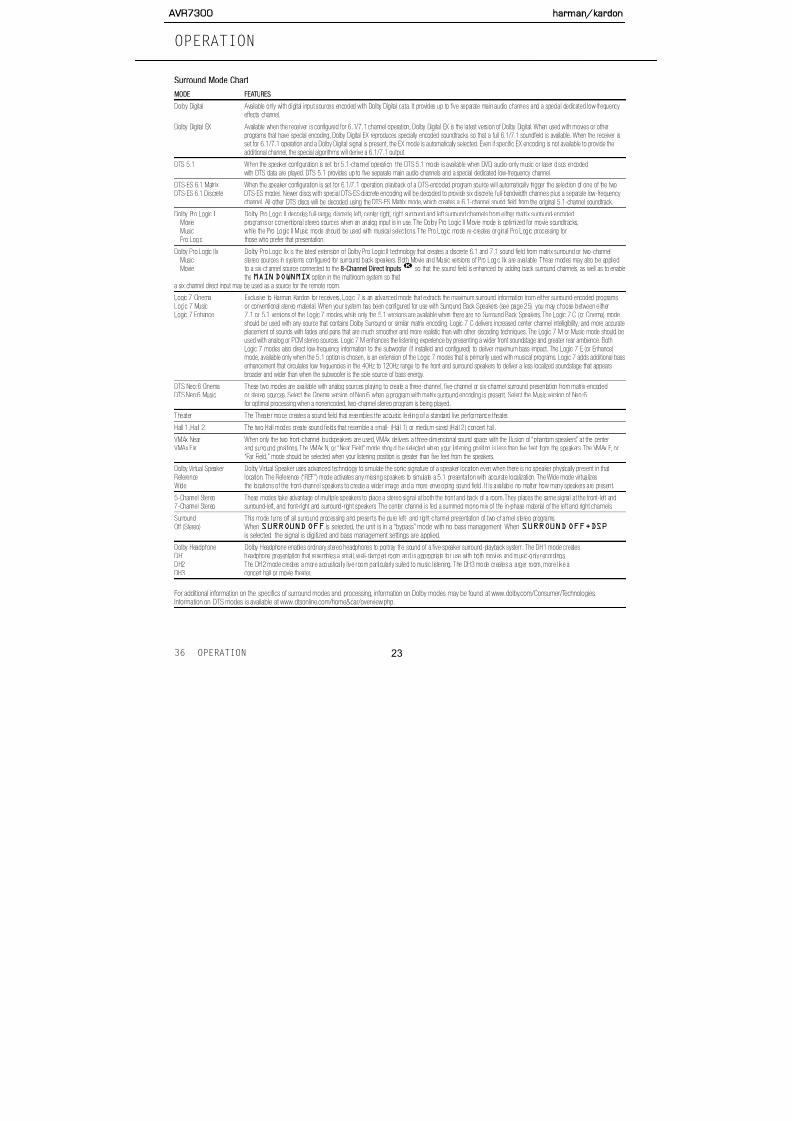
Surround Mode Chart
MODE FEATURESDolby Digital Available only with digital input sources encoded with Dolby Digital data. It provides up to five separate main audio channels and a special dedicated low-frequency
effects channel.
Dolby Digital EX Available when the receiver is configured for 6.1/7.1 channel operation, Dolby Digital EX is the latest version of Dolby Digital. When used with movies or otherprograms that have special encoding, Dolby Digital EX reproduces specially encoded soundtracks so that a full 6.1/7.1 soundfield is available. When the receiver isset for 6.1/7.1 operation and a Dolby Digital signal is present, the EX mode is automatically selected. Even if specific EX encoding is not available to provide theadditional channel, the special algorithms will derive a 6.1/7.1 output.
DTS 5.1 When the speaker configuration is set for 5.1-channel operation, the DTS 5.1 mode is available when DVD, audio-only music or laser discs encodedwith DTS data are played. DTS 5.1 provides up to five separate main audio channels and a special dedicated low-frequency channel.
DTS-ES 6.1 Matrix When the speaker configuration is set for 6.1/7.1 operation, playback of a DTS-encoded program source will automatically trigger the selection of one of the twoDTS-ES 6.1 Discrete DTS-ES modes. Newer discs with special DTS-ES discrete encoding will be decoded to provide six discrete, full-bandwidth channels plus a separate low-frequencychannel. All other DTS discs will be decoded using the DTS-ES Matrix mode, which creates a 6.1-channel sound field from the original 5.1-channel soundtrack.
Dolby Pro Logic II Dolby Pro Logic II decodes full-range, discrete, left, center right, right surround and left surround channels from either matrix surround-encodedMovie programs or conventional stereo sources when an analog input is in use. The Dolby Pro Logic II Movie mode is optimized for movie soundtracks,Music while the Pro Logic II Music mode should be used with musical selections. The Pro Logic mode re-creates original Pro Logic processing forPro Logic those who prefer that presentation.
Dolby Pro Logic IIx Dolby Pro Logic IIx is the latest extension of Dolby Pro Logic II technology that creates a discrete 6.1 and 7.1 sound field from matrix surround or two-channelMusic stereo sources in systems configured for surround back speakers. Both Movie and Music versions of Pro Logic IIx are available. These modes may also be appliedMovie to a six-channel source connected to the 8-Channel Direct Inputs so that the sound field is enhanced by adding back surround channels, as well as to enable
the MAINDOWNMIX option in the multiroom system so that a six channel direct input may be used as a source for the remote room.
Logic 7 Cinema Exclusive to Harman Kardon for receivers, Logic 7 is an advanced mode that extracts the maximum surround information from either surround-encoded programsLogic 7 Music or conventional stereo material. When your system has been configured for use with Surround Back Speakers (see page 25), you may choose between eitherLogic 7 Enhance 7.1 or 5.1 versions of the Logic 7 modes, while only the 5.1 versions are available when there are no Surround Back Speakers. The Logic 7 C (or Cinema) mode
should be used with any source that contains Dolby Surround or similar matrix encoding. Logic 7 C delivers increased center channel intelligibility, and more accurateplacement of sounds with fades and pans that are much smoother and more realistic than with other decoding techniques. The Logic 7 M or Music mode should beused with analog or PCM stereo sources. Logic 7 M enhances the listening experience by presenting a wider front soundstage and greater rear ambience. BothLogic 7 modes also direct low-frequency information to the subwoofer (if installed and configured) to deliver maximum bass impact. The Logic 7 E (or Enhance)mode, available only when the 5.1 option is chosen, is an extension of the Logic 7 modes that is primarily used with musical programs. Logic 7 adds additional bassenhancement that circulates low frequencies in the 40Hz to 120Hz range to the front and surround speakers to deliver a less localized soundstage that appears
OPERATION
AVR7300 harman/kardon

5/13/2018 AVR7300 sm - slidepdf.com
http://slidepdf.com/reader/full/avr7300-sm 24/158
OPERATION
dynamic range and significant improvements to signal-
to-noise ratios. In addition, digital systems have the capa-
bility to deliver an additional channel that is specifically
devoted to low-frequency information. This is the “.1”
channel referred to when you see these systems
described as “5.1,” “6.1” or “7.1.” The bass channel is
separate from the other channels, but since it is inten-
tionally bandwidth-limited, sound designers have given it
that unique designation.
Dolby Digital
Dolby Digital is a standard part of DVD, and high-defini-tion (HDTV) broadcasts and is available on specially
encoded LD discs and satellite broadcasts.
An optional, external RF demodulator is required
to use the AVR 7300 to listen to the Dolby Digital
soundtracks available on laser discs. Connect the RF
output of the LD player to the demodulator and then
connect the digital output of the demodulator to the
Optical or Coaxial Inputs ®† of the
AVR 7300. No demodulator is required for use withDVD players or DTS-encoded laser discs.
DTS
DTS is a digital audio system capable of delivering 5.1
or 6.1 discrete or matrix sound field reproduction.
Although both DTS and Dolby Digital are digital, they
use different methods of encoding the signals, and
thus they require different decoding circuits to convert
the digital signals back to analog.
method for doing this will vary with each player. In
some cases, the proper menu choice will be “Original,”
while in others it will be “DTS.” Consult the owner’s
manual for your player to find the specific information
to find the proper setting.
Selecting a Digital Source
To utilize either digital mode, you must have properly
connected a digital source to the AVR 7300. Connect
the digital outputs from DVD players, HDTV receivers,
satellite systems or CD players to the Optical or
Coaxial Inputs ®† . In order to provide
a backup signal and a source for analog stereo record-ing, the analog outputs provided on digital source
equipment should also be connected to their appropri-
ate inputs on the AVR 7300 rear panel (e.g., connect
the analog stereo audio output from a DVD to the DVD
Audio Inputs © on the rear panel when you connect
the source’s digital outputs).
If you have not already configured an input for a digital
source using the on-screen menus as shown on
page 23, first select the desired input using theremote or front-panel controls, as outlined in this man-
ual. Next, press the Digital Select Button pand then using the ⁄ / ¤ Navigation Button oon the remote or the ‹ / › Buttons on the front
panel, choose any OPTICAL or COAXIAL
inputs, as they appear in the Upper Display Line #or on-screen display.When the digital source is playing,
the AVR 7300 will automatically detect which type of
digital data stream is being decoded and display that
before that portion of the display returns to the normal
surround mode indication.
For Dolby Digital and DTS sources, a three-digit indica-
tion will appear, showing the number of channels present
in the data. An example of this type of display is 3/2/.1.
The first number in the display message indicates how
many discrete front-channel signals are present.
• A “3” tells you that separate front left, center and
front right signals are available. This will be displayed
for Dolby Digital 5.1 and DTS 5.1 programs.
• A “2” tells you that separate front left and right sig-
nals are available, but there is no discrete center
channel signal. This will be displayed for Dolby
Digital bitstreams that have stereo program material.
• A “1” tells you that there is only a mono channel
available in the Dolby Digital bitstream.
The middle number in the display message indicates
how many discrete surround channel signals are present.
• A "3" tells you that separate, discrete left surround,
center back surround and right surround signals are
present. This is available only on discs with DTS-ES
digital audio.
• A “2” tells you that separate surround left and right
signals are available. This will be displayed for Dolby
Digital 5.1 and DTS 5.1 programs.
• A “1” tells you that there is only a single, surround-
8
6
1210
1210
AVR7300 harman/kardon

5/13/2018 AVR7300 sm - slidepdf.com
http://slidepdf.com/reader/full/avr7300-sm 25/158
When Dolby Digital 3/2/.1 or DTS or DTS-ES signals
are being played, the DPR will automatically switch to
the proper surround mode, and no other processingmay be selected. When a Dolby Digital signal with a
3/1/0 or 2/0/0 signal is detected, you may select any
of the Dolby surround modes.
When DS-OFF appears as a message, it indicates
that there is no Dolby Surround data flag in the audio
bitstream. Similarly, EX-OFF indicates that there
is no Dolby Digital EX data flag. In the case of a
DS-OFF message, you may manually select a
Dolby Pro Logic mode to add a multichannel presen-tation to the stereo material. In the case of the
EX-OFF message, when your system is config-
ured for surround back speakers you may manually
select Dolby Digital EX as the processing mode to add
rear surround speakers to the sound field.
It is always a good idea to check the channel data to
make certain that it matches the audio logo informa-
tion shown on the back of a DVD package. In some
cases, you will see an indication for “2/0/0” evenwhen the disc contains a full 5.1, or 3/2/.1, signal.
When this happens, check the audio output settings
for your DVD player or the audio menu selections for
the specific disc being played to be sure that the
player is sending the correct signal to the AVR.
An UNLOCK message may appear in the Lower
Display Line $. This is your indication that the digi-
tal audio data stream has been interrupted or is no
In most cases, this will bePCM 44.1kHz or
PCM48kHz, though in the case of specially
mastered, high-resolution audio discs, you will see a
PCM96kHz indication. Note that the sampling rate
displayed is that of the incoming digital signal, and not
the upsampled rate that may be applied to PCM sources
when Dolby Pro Logic, Pro Logic II or Pro Logic IIx
processing is applied, as shown on pages 25–26.
During PCM playback you may select any surround
mode except one of the Dolby Digital or DTS/DTS-ES
modes. However, when a CD with HDCD encoding is
being played you must select the Surround Off (stereo)mode to take advantage of the HDCD process.
HDCD Playback
High Definition Compatible Digital,® or HDCD, discs are
recorded using a 20-bit encoding and other propri-
etary processing for the ultimate in CD listening. When
an HDCD-encoded disc is playing and the CD
player is connected using a digital connection, the
AVR 7300 will automatically recognize the HDCD
encoding and activate the circuits required for properplayback, provided that the Surround Off mode is
selected. An HDCD message will appear in the Lower
Display Line $ to confirm the HDCD playback.
HDCD playback is limited to two-channel stereo only.
Speaker/Channel Indicators
In addition to the bitstream indicators, the AVR 7300
features channel-input indicators that show how many
channels of digital information are being received
Dolby Digital soundtrack to trigger only the “L” and “R”
indicators.
NOTE: Many DVD discs are recorded with both “5.1”
and “2.0,” and Dolby Digital and DTS versions of the
same soundtrack. When playing a DVD, always be
certain to check the type of material on the disc. Most
discs show this information using icons on the back of
the disc jacket. When a disc offers multiple soundtrack
choices, you may have to make some adjustments to
your DVD player (usually with the “Audio Select” button
or in a menu screen on the disc) to send a full 5.1
feed to the AVR 7300 or to select between DolbyDigital or DTS. It is also possible for the type of signal
feed to change during the course of a DVD’s play-
back. In some cases, the previews or special material
will be recorded in 2.0 audio, while the main feature is
available in 5.1 audio. The AVR 7300 will automatically
sense changes to the bitstream and channel count
and reflect them in these indicators.
The letters used by the Speaker/Channel Input
Indicators @ also flash to indicate when a bitstream
has been interrupted. This will happen when a digital
input source is selected before the playback starts, or
when a digital source such as a DVD is paused. The
flashing indicators, along with theUNLOCK mes-
sage in the Lower Display Line $, remind you
that the playback has stopped due to the absence
of a digital signal and not through any fault of the
AVR 7300. This is normal, and the digital playback
will resume once the playback is started again.
OPERATION
AVR7300 harman/kardon
5/13/2018 AVR7300 sm - slidepdf.com
http://slidepdf.com/reader/full/avr7300-sm 26/158
OPERATIONOPERATION
MP3 Audio Playback
The AVR 7300 is one of the few receivers equipped
for onboard decoding for the MP3 audio format usedby computers and portable audio devices. By offering
MP3 decoding, the AVR 7300 is able to deliver pre-
cise conversion of the digital signals to an analog out-
put, along with the benefits of listening to the MP3
audio through the AVR 7300’s high-power amplifier
and the speakers from your surround system, rather
than the smaller speakers and low-powered amplifiers
typically used with computers.
To take advantage of the AVR 7300’s MP3 capabili-
ties, simply connect the S/P-DIF output of a comput-
er’s sound card or the S/P-DIF output of a portable
digital audio device to either the rear panel Digital
Inputs ®† or the front-panel Digital Inputs
. When the digital signal is available, the Lower
Display Line $ will indicate that an MP3 bitstream
is present, and the audio will begin playing.
NOTES:• The AVR 7300 is only capable of playing signals in
the MP3 (MPEG 1/Layer 3) format. It is not com-
patible with other computer audio codecs.
• The digital audio input signal may be either optical
or coaxial, but the signal must be in the S/P-DIF
format. Direct connection of USB or serial data
outputs is not possible, even though the signals
are in the MP3 format. If you have any questions
the high-quality audio reproduction possible with a
home theater system, as well as enable the use of
surround processing modes such as Logic 7, togreatly enhance downloaded or streaming audio
playback.
IMPORTANT NOTES ON DIGITAL PLAYBACK:
• When the digital playback source is stopped, or
in a pause, fast forward or search mode, digital
audio data will momentarily stop, and the channel
position letters inside the Speaker/Channel Input
Indicators @ will flash and an UNLOCK mes-
sage may appear. This is normal and does not indi-
cate a problem with either the AVR 7300 or the
source machine. The AVR 7300 will return to digital
playback as soon as the data is available.
• Some source devices, particularly cable set-top
boxes, will switch back and forth between digital and
analog audio outputs, depending on the channel
being watched. To avoid losing sound with this type
of product, it is recommended that you connect
both the digital and analog audio outputs of the
source to the AVR 7300, with the digital audio input
set as the default following the steps shown on
page 23. The AVR will monitor the digital data
stream and when it is interrupted the sound will
mute briefly and possibly display an UNLOCK
message while it switches to the analog audio input.
This switching is not a fault of either the AVR or the
cable box, as it is caused by the use of different
select the tuner as an input. The tuner may be
selected from the front panel by either pressing the
Input Source Selector 7 until the tuner is activeor by pressing the Tuner Band Selector 5.
2. Press the AM/FM Button or Tuner Band
Selector 5 again to switch between AM and FM
so that the desired frequency band is selected.
3. Press the Tuner Mode Selector 8 l to select
manual or automatic tuning.
When the button is pressed so that AUTO or
AUTO/STEREO appears in the Upper
Display Line #, each press of the Tuning
Selectors 4w will put the tuner in a scan
mode that seeks the next higher or lower frequency
station with acceptable signal strength. An AUTO
STTUNED indication will momentarily appear
when the station stops at a stereo FM station, and
an AUTO TUNED indication will momentarily
appear when an AM or monaural FM station is
tuned. Press the Tuning Selectors 4w againto scan to the next station.
When the button is pressed so that MANUAL
or MANUAL/MONO appears in the Upper
Display Line #, each tap of the Tuning
Selectors 4w will increase or decrease the
frequency by one increment. When the tuner
receives a strong enough signal for adequate
reception,MANUALTUNED will appear
in the Lower Display Line $
34
12
10
AVR7300 harman/kardon

5/13/2018 AVR7300 sm - slidepdf.com
http://slidepdf.com/reader/full/avr7300-sm 27/158
To enter a station into the memory, first tune the sta-
tion using the steps outlined above. Then:
1. Press the Memory Button on the remote;
the station’s frequency will flash.
2. Within five seconds, press the Numeric Keys kcorresponding to the memory location where you
wish to store this station’s frequency. Once entered,
the preset number will appear in the Upper
Display Line #.
3. Repeat the process after tuning any additional
stations to be preset.
Recalling Preset Stations
• To manually select a station previously entered in
the preset memory, press the Numeric Keys kfor the desired station’s memory location.
• To manually scroll through the list of preset stations,
press the Preset Stations Selector Button
6v on the front panel or remote.
Recording
In normal operation, the audio or video source
selected for listening through the AVR 7300 is sent to
the record outputs. This means that any program you
are watching or listening to may be recorded simply
by placing machines connected to the outputs for
Tape Outputs ∂ or Video 1/Video 2 Outputs
π∆ in the record mode.
Front-Panel Connections
In addition to the rear-panel digital and analog outputs,the AVR 7300 offers Harman Kardon’s exclusive con-
figurable front-panel output-jack feature. For easy con-
nection of portable devices, you may switch the front-
panel Video 5 Jacks from an input to an output
by following these steps:
1. Press the OSD ButtonU to view the
MASTERMENU (Figure 1).
2. Press the Set Button q to enter theIN/OUTSETUP menu (Figure 2).
3. Press the ¤ Navigation Button o so that the
on-screen cursor is next to VIDEO 5.
4. Press the Set Button q and then press the‹ / › Navigation Button o so that the word
OUT is highlighted.
5. Press the Set Button q to enter the change.
6. Press the OSD ButtonU to exit the menus and
return to normal operation.
Once the setting is made, the Input/Output Status
Indicator will turn red, indicating that the jacks
are now an output, instead of in the default setting as
an input. Once changed to an output, the setting will
remain as long as the AVR 7300 is turned on, unless
the setting is changed in the OSD menu system, as
described above. However, once the AVR 7300 is
Once the reference level has been set, press the
Channel Select Button n and FRONT L
LEVEL will appear in the Lower Display Line$. To change the level, first press the Set Button
q, and then use the ⁄ / ¤ Navigation Button
o to raise or lower the level. DO NOT use the vol-
ume control, as this will alter the reference setting.
Once the change has been made, press the Set
Button q and then press the ⁄ / ¤ Navigation
Button o to select the next output-channel location
that you wish to adjust. To adjust the subwoofer level,
press the ⁄ / ¤ Navigation Button o until
WOOFERLEVEL appears in the Lower Display
Line $ or on-screen display.
Repeat the procedure as needed until all channels
requiring adjustment have been set. When all adjust-
ments have been made and no further adjustments
are made for five seconds, the AVR 7300 will return to
normal operation.
The channel output for any input may also be adjusted
using the full-OSD on-screen menu system. First, set
the volume to a comfortable listening level using the
Volume Control )rî. Then, press the OSD
ButtonU to bring up the MASTERMENU
(Fig. 1). Press the ¤ Navigation Button o until
the on-screen cursor is next to the CHANNEL
ADJUST line. Press the Set Button q to
activate the CHANNELADJUST menu (Fig. 13).
15
14
39
OPERATIONOPERATION
AVR7300 harman/kardon

5/13/2018 AVR7300 sm - slidepdf.com
http://slidepdf.com/reader/full/avr7300-sm 28/158
make other adjustments. If you have no other adjust-
ments to make, press the OSD ButtonU to exit
the menu system.
NOTE: Output levels may be separately trimmed for each
surround mode. If you wish to have different trim levels for
a specific mode, select that mode and then follow the
instructions shown above.
Dim Function
Since the AVR 7300 will often be used when movies
or other video programming is viewed under low-light
conditions, you may wish to lower the brightness of
the front-panel displays and indicators so that they do
not distract from the video presentation. You may dim
the displays using the menu system, as shown on
page 42, or you may control the brightness directly
from the remote.
Simply press the Dim Button m once to dim the
front panel to half the normal brightness level; press
it again to turn the displays off. Note that when the
displays are dimmed or turned off, the lighting around
the Standby/On Button 1 will remain lit as a
reminder that the AVR is still turned on.
Note that all changes to the front-panel brightness
level remain in effect only until the AVR is turned off;
the displays will return to full brightness after the AVR
is turned on again. To return the displays to full bright-
ness without turning the unit off, press the Dim
Button m as needed until the displays are on.
OPERATION
AVR7300 harman/kardon

5/13/2018 AVR7300 sm - slidepdf.com
http://slidepdf.com/reader/full/avr7300-sm 29/158
TROUBLESHOOTING GUIDE
SYMPTOM CAUSE SOLUTION
Unit does not function when Main • No AC Power • Make certain that the AC power cord is plugged into a live outlet Power Switch is pushed • Check to see whether the outlet is switch-controlled
Display lights, but no sound • Intermittent input connections • Make certain that all input and speaker connections are secure
or picture • Mute is on • Press Mute Button
• Volume control is down • Turn up the volume control
Unit turns on, but front-panel • Display brightness is turned off • Follow the instructions in the Display Brightness section
display does not light up on page 42 so that the display is set to VFD FULL
No sound from any speaker; • Amplifier is in protect ion mode • Check speaker wire connections for shorts at receiver and
light around power switch is red due to possible short speaker ends
• Amplifier is in protection mode • Contact your local Harman Kardon service center
due to internal problems
No sound from surround or • Incorrect surround mode • Select a mode other than Stereo
center speakers • Input is monaural • There is no surround information from mono sources
• Incorrect configuration • Check speaker mode configuration
• Stereo or Mono program material • The surround decoder may not create center- or rear-channel
information from nonencoded programs
Unit does not respond to • Weak batteries in remote • Change remote batteries
remote commands • Wrong device selected • Press the AVR selector
• Remote sensor is obscured • Make certa in that the front-panel sensor is visible to the remote,
or connect remote sensor
Intermittent buzzing in tuner • Local interference • Move the unit or antenna away from computers, f luorescent
lights, motors or other electrical appliances
An UNLOCK message appears • The type of digital audio stream • Wait a second or two for the unit’s processor to recognize the new data
in the display and/or the letters has been changed stream and automatically resume playback
33
AVR7300 harman/kardon

5/13/2018 AVR7300 sm - slidepdf.com
http://slidepdf.com/reader/full/avr7300-sm 30/158
30
AVR7300 harman/kardon

5/13/2018 AVR7300 sm - slidepdf.com
http://slidepdf.com/reader/full/avr7300-sm 31/158
AVR7300 Exploded View Parts List
No. Part No. Description Q'ty
1 H01-SWA2B21PDA&-7 SW PUSH POWER SDDLB15700 1
2 H01-TXPWMMD05B0-5 MN X'FORMER AVR7300 120V TRANSFORMER 1
3 H01-ZMB01S00100-5 BKT HEADPHONE JACK 14 H01-ZMD05S02A00-1 AL DOOR AVR7300 1
5 H01-ZMC11S00300-2 AL PANEL AVR430/630 1
6 H01-ZMC11S06A00-3 SPRING STOPPER AVR430/630 1
7 H01-ZMC11S12A00-8 CAP BUTTON STAND-BY AVR430/630 1
8 H01-ZMC12S09A00-4 BKT HEATSINK 15
9 H01-ZMC12S20A00-2 BADGE AL HARMAN/KARDON SILVER 1
10 H01-ZMD05S03A00-2 HEATSINK 3CH AVR7300 1
11 H01-ZMD05S04A00-3 HEATSINK 4CH AVR7300 1
12 H01-ZMD05S07A00-6 CHASSIS FRONT AVR7300 1
13 H01-ZMD05S08A00-7 COVER TOP AVR7300 1
14 H01-ZMD05S08B00-9 BKT TRANS BOTTOM AVR7300 1
15 H01-ZMD05S09A00-8 BKT TOP 2
16 H01-ZMD05S10A00-8 BKT SIDE 2
17 H01-ZMD05S11A00-9 PANEL REAR AVR7300US 1
18 H01-ZMD05S12AYE-8 STUD STANDOFF HEX M4X0.7 6X15H 2
19 H01-ZMD05S13A00-0 CHASSIS MAIN AVR7300 1
20 H01-ZMD05S13AYE-9 STANDOFF HEX M4X0.7 6X55H 2
21 H01-ZMD05S14AYE-A STANDOFF HEX M4X0.7 6X34H 4
22 H01-ZMD05S15AYE-0 STUD STANDOFF HEX M4X0.7 6X71.6H 223 H01-ZMD05S15A00-2 BKT SUPPLY 1
24 H01-ZMD05S16A00-3 BKT HINGE AVR7300 2
25 H01-ZPC1004GASG-0 BUTTON 7 KEY 1
26 H01-ZPC1018GART-7 FILTER VFD 1
27 H01-ZMGEN00GAGY-0 AL LOGO BADGE TOP 1
28 H01-ZPD0515GAMW-A VOLUME KNOB 1
29 H01-ZPD0316GASG-A COVER KNOB 1
30 H01-ZPD0317GACR-4 CAP KNOB VOLUMN 1
31 H01-ZPD0501GAGY-9 FRONT PANEL AVR7300 1
AVR7300 harman/kardon

5/13/2018 AVR7300 sm - slidepdf.com
http://slidepdf.com/reader/full/avr7300-sm 32/158
AVR7300 Exploded View Parts List
No. Part No. Description Q'ty
J1 H01-SOSP20117NN-6 JACK SPEAKER 2P B30290117N BK/WH 1
J2 H01-SOSP20118NN-8 JACK SPEAKER 2P B30290118N BK/BU 1
J3 H01-SOSP20119NN-A JACK SPEAKER 2P B30290119N BK/BRN 1J4 H01-SOSP20115NN-2 JACK SPEAKER 2P B30290115N GY/BK D/N 1
J5 H01-SOSP20116NN-4 JACK SPEAKER 2P B30290116N TAN/BK 1
J6 H01-SOSP40164NN-1 JACK SPEAKER 4P B30490164N GN/BK/R/B 1
J7 H01-SORA40RSANN-6 JACK RCA 4P JB040131ZN GN BN PP TA 2
J8 H01-SORA40RSCNN-A JACK RCA 4P JB040131QN WH BU RD GY 3
J9 H01-SOJB04013HN-5 JACK RCA 4P OR ,OR, OR, OR JB040131HN 2
J10 H01-SORA8OSC5N8-2 JACK S-VIDEO 1P C40160261N 1
J11 H01-SOSS9CKX3NN-9 JACK PHONE 6.35 H70980110S 9P BK 1
J12 H01-SWE3AEC11S1-8 VOLUME ENCODER EC11B20203 1
J13 H01-VDHCA18LL03-7 FL HCA-18LL03 1
J14 SOMOD7400NN-6 JACK MODULAR 7400-621002 1
J15 H01-SOR12BJ12NN-3 JACK RCA 12P BJ120154JN 1
J16 H01-SORA11Y00NN-5 JACK RCA+S VIDEO C5016031DN 9
J17 H01-SORA40GNDNN-7 JACK RCA 4P JB040131PN WWRR 4
J18 H01-SORA64105NN-5 JACK RCA 6P JB060132PN 1
J19 H01-SOAC3A206NN-5 JACK AC OUTLET 3P A206D0054P 1
J20 H01-SORA21502NN-2 CON PHONO SCKT RCA 2P W/GNDCAP CJ020009 1
J21 H01-SOXA27014NN-9 CON MAINS INLET A/C INLET 7014-NGP AC05-4S0 1
J22 SOPA96063NN-0 JACK D-SUB 9P 87204-6063 W/DUST COVER BK 1J23 H01-SOJW2350SNN-A JACK PHONE 3.6 EP-1401A 1P BK 4
J24 H01-SOTOR179LBA-0 D-LEM TORX-179L 4
J25 H01-SOTOT179LBA-7 D-LEM TOTX-179L 2
J26 H01-SORA3313PNN-3 CON PHONO SCKT RCA-313P 3 PINS
S5 ZSMWM4008BZ-2 SCREW M.S M4X8 W/H ZN PLATED 11
S6 ZSTBM0318TZ-3 SCREW ST BH 3X18 3
S4 ZSTBM3008BY-1 SCREW ST BH 3X8 3
S1 ZSTBM3010BB-5 SCREW ST BH 3X10 62

5/13/2018 AVR7300 sm - slidepdf.com
http://slidepdf.com/reader/full/avr7300-sm 33/158
CIRCUIT DESCRIPTIONAVR7300

5/13/2018 AVR7300 sm - slidepdf.com
http://slidepdf.com/reader/full/avr7300-sm 34/158
1.SURROUND CIRCUIT
COAXIAL 1
COAXIAL 2
COAXIAL 3
COAXIAL 4
OPTICAL 1
OPTICAL 2
OPTIACL 3
DIGITAL OUTPUT
COAXIAL
OPTICAL
ANALOG INPUT
ANALOG
FL
FR
SL
S/PDIF
INPUT
U - COM
External 8M Flash
Memory
M
a
s
t
e
TONE
AMP
FL,FR
C,SL,SR,SW,SBL,SB
DIG ITAL INPUT
OPTICAL 4
AVR7300 h

5/13/2018 AVR7300 sm - slidepdf.com
http://slidepdf.com/reader/full/avr7300-sm 35/158
100 99 98 97 96 95 94 93 92 91 90 89 88 87 86 85 84 83 82 81
1 80
2 79
3 78
4 77
5 FL STB 76
6 FL BLK 75
7 FL DI 74
8 FL CLK 73
9VDD
72
10GND
71
11 70
12 69
13 68
14 67
15 66
16 65
17 64
18 63
19 62
20 61
21 60
22 59
23 58
24 57
25 56
26 55
27 54
Upd70F3033BGF-3BA PORT DEFINE FOR AVR7300
P14/SO1/TXD0
P15//SCK1/ASCK0
P20/SI2/SDA1
P21/SO2
P22//SCK2/SCL
P23/RXD1/SI3
P24/TXD1/SO3
P25/ASCK1//SCK3
EVDD
EVSS
P26/TI2/TO2
P27/TI3/TO3
P30/TI00
P31/TI01
P32/TI10/SI4
P33/TI11/SO4
P34/TO0/A13//SCK4
P35/TO1/A14
P36/TI4/TO4/A15
P37/TI5/TO5
IC/VPP
P100/RTP0/KR0/A5
P101/RTP1/KR1/A6
P102/RTP2/KR2/A7
P103/RTP3/KR3/A8
P104/RTP4/KR4/A9
P105/RTP5/KR5/A10
P73/ANI3
P 1 3 / S I 1 / R X D 0
RS 232 TX
VPP CONTROL
HDCD GAIN
FL RESET /STB
FL DATA IN/BLK
FL DATA OUT/DI
FL CLK / CLK
ADC RESET
CODEC RESET
RMC IN
CODEC CE /DAC_4391_RST
MULTI ROOM IN
CODEC CLK
CODEC DATA OUT
CODEC DATA IN
CODEC INT
4391 CONTROL
DSP RESET
DSP HINBSY
DSP INTERQ AB
DSP CLK AB
DSP CE AB
DSP DATAOUT AB
P72/ANI2
P71/ANI1
P70/ANI0
AVREF
AVDD
AVSS
P65/A21
P64/A20
P63/A19
P62/A18
P61/A17
P60/A16
P57/AD15
P56/AD14
P55/AD13
P54/AD12
P53/AD11
P52/AD10
P51/AD9
P50/AD8
BVSS
BVDD
P47/AD7
P46/AD6
P45/AD5
P44/AD4
N.C
AD KEY2
AD KEY1
MULTI MUTE
REC MUTE
POWER MUTE
SUB MUTE
S MUTE
C MUTE
F MUTE
PLL DATA OUT
PLL DATA IN
PLL CLK
PLL CE
TUNED
T MUTE
SB MUTE
9273 CE3/9162 CE2
9273 CE1/9162 CE/9163 CE
A CLK
A DATA
P 1 2 / / S C K 0 / S C L 0
P 1 1 / S O 0
P 1 0 / S I 0 / S D A 0
P 0 7 / I N T P 6
P 0 6 / I N T P 5 / R T P T R G
P 0 5 / I N T P 4 / A D T R G
P 0 4 / I N T P 3
P 0 3 / I N T P 2
P 0 2 / I N T P 1
P 0 1 / I N T P 0
P 0 0 / N M I
P 8 3 / A N I 1 1
P 8 2 / A N I 1 0
P 8 1 / A N I 9
P 8 0 / A N I 8
P 7 6 / A N I 6
2R
OD
OC
OC
A S
DS
P
C
FO
RD
RC
PED
N
S NC P
O
C
N
T
S
HN
CSRS
E
2
E
1
uPD70F3033B
P 7 5 / A N I 5
P 7 4 / A N I 4
P 7 7 / A N I 7
C
M
S HN
Gerally, 47K Pull-down, Flash 8V
N.C
AVR7300 har

5/13/2018 AVR7300 sm - slidepdf.com
http://slidepdf.com/reader/full/avr7300-sm 36/158
uPD70F3033B (V850/SB1) PORT ASSIGNME
PIN V850 NAME RECEVIER NAME IN/OUT Function An
1 P14/SO1/TXD0 RS-232 TX TX For CPU FLASH UPGRADE UA
2 P15/SCK1/ASCK0 VPP_CONTROL OUT For Flash Upgrade VPP Contro
3 P20/SI2/SDA1 HDCD GAIN OUT HDCD GAIN
4 P21/SO2 N.C OUT OPEN
5 P22/SCK2/SCL1 FIP RST / FL STB OUT FIP DRIVER IC RESET / FL ST
6 P23/RXD1/SI3 FIP SI / FL BLK SI FIP DRIVER IC DATA IN / FL B
7 P24/TXD1/SO3 FIP SO / FL DI SO FIP DRIVER IC DATA OUT / FL
8 P25/ASCK1/SCK3 FIP CLK / FL CLK SCK FIP DRIVER IC CLOCK OUT (N
9 EVDD EVDD POWER Connected VDD10 EVSS EVSS POWER Connected GND
11 P26/TI2/TO2 ADC RESET OUT ADC RESET(DSP)
12 P27/TI3/TO3 CODEC_RESET OUT CODEC RESET(DSP)/DAC RE
13 P30/TI00 RMC_IN CAPTURE REMOCON IN
14 P31/TI01 CODEC_CE OUT CODEC CHIP ENABLE(DSP)/D
15 P32/T110/S14 RMC_MULTI CAPTURE MULTI ROOM REMOCON
16 P33/TI11/SO4 CODEC CLK OUT CODEC CLK(DSP)
17 P34/TO0/SCK4 CODEC_DATA_OUT OUT CODEC DATA_OUT(DSP)18 P35/TO1 CODEC_DATA_IN IN CODEC DSP_IN(DSP)
19 P36/TI4/TO4 CODEC_INT IN CODEC INT(DSP)
20 P37/TI5/TO5 4391 CONTROL OUT 4391 CONTROL
21 IC/VPP VPP IN Normally, Opetation 47K Pull_
22 P100/RTP0/KR0 DSP_RESET OUT CS49400 RESET(DSP)
23 P101/RTP1/KR1 DSP_HINBSY IN CS49400 HINBSY(DSP)
24 P102/RTP2/KR2 DSP INTERQ AB IN CS49400 INTERQ AB(DSP)
AVR7300

5/13/2018 AVR7300 sm - slidepdf.com
http://slidepdf.com/reader/full/avr7300-sm 37/158
34 /RESET RESET IN LOW ACTIVE
35 XT1 N.C IN Pull_Down
36 XT2 N.C OUT OPEN
37 REGC REGC POWER Connect VDD
38 X2 Fx_OUT OUT Connected 20.00MHz RESONA
39 X1 Fx_IN IN Connected 20.00MHz RESONA
40 VSS VSS POWER Connected GND
41 VDD VDD POWER Connected VDD
42 CLKOUT N.C OUT OPEN (STOP MODE : LOW)
43 P90/LBEN/WRL ADC MODE 0 OUT ADC MODE 0(DSP)
44 P91/UBEN ADC MODE 1 OUT ADC MODE 1(DSP)
45 P92/RW/WRH HP MUTE OUT HEADPHONE MUTE
46 P93/DSTB/RD EEPROM DATA IN/OUT EEPROM DATA47 P94/ASTB EEPROM CLK OUT EEPROM CLK
48 P95/HLDAK VOL IC CE OUT TC9481CE
49 P96/HLDRQ 4094 CE OUT 4094 CHIP ENABLE
50 P40 4094 CLK OUT 4094 CLK
51 P41 4094 DATA OUT 4094 DATA
52 P42 9482/59/81 DATA OUT 9482/59/81 IC DATA
53 P43 9482/59/81 CLK OUT 9482/59/81 IC CLK
54 P44 A DATA OUT 9273, 9162 , 9163 IC DATA55 P45 A CLK OUT 9481,9273,9162,9163 IC CLK
56 P46 9273 CE1 OUT 9273, 9162, 9163 CHIP ENAB
57 P47 9273_CE3 OUT 9273, 9162 CHIP ENABLE
58 BVDD BVDD POWER Connected VDD
59 BVSS BVSS POWER Connected GND
60 P50 T_MUTE OUT TUNER MUTE OUT
61 P51 TUNED IN TUNED CHECK IN
AVR7300 h

5/13/2018 AVR7300 sm - slidepdf.com
http://slidepdf.com/reader/full/avr7300-sm 38/158
71 P63 P MUTE OUT POWER MUTE
72 P64 RECMUTE OUT REC MUTE
74 AVDD AVDD POWER Connected VDD
75 AVSS AVSS POWER Connected GND
76 AVREF AVREF POWER Vad
77 P70/ANI0 AD KEY1 ADIN A/D KEY INPUT1
78 P71/ANI1 AD KEY2 ADIN A/D KEY INPUT2
79 P72/ANI2 N.C ADIN Connected Register with VDD
80 P73/ANI3 N.C ADIN Connected Register with VDD
81 P74/ANI4 ENCODE1 IN VOLUME ENCODER INPUT 1
82 P75/ANI5 ENCODE2 IN VOLUME ENCODER INPUT 2
83 P76/ANI6 CV/SY/RGB SYNC ADIN CV/SY/RGB SYNC DETECT (A
84 P77/ANI7 HP_IN IN HEADPHONE INPUT
85 P80/ANI8 TUNER STEP IN TUNER OPTION L : USA
86 P81/ANI9 COMPONENT INPU IN COMPONENT INPUT HD/SD
87 P82/ANI10 PROTECTION IN PROTECTION IN
88 P83/ANI11 N.C IN Connected Register with GND
89 P00/NMI STANDBY OUT MAIN POWER ON/OFF
90 P01/INTP0 POWER DOWN INTP0 POWER DOWN CHECK & WAK
91 P02/INTP1 RDS_CLOCK INTP1 RDS_CLOCK *EU ONLY
92 P03/INTP2 RDS_DATA IN RDS_DATA *EU ONLY93 P04/INTP3 CODEC MUTE OUT CODEC MUTE
94 P05/INTP4/ADTRG NT/PAL CHECK IN SYNC PLUSE CHECK(OSD IC
95 P06/INTP5/RTPTRG SYNC DETECT IN SYNC CHECK(OSD IC 29PIN)
96 P07/INTP6 A18 OUT AT49LV8192A PIN A18
97 P10/SI0 OSD CE OUT OSD CHIP ENABLE
98 P11/SO0 OSD CLK OUT OSD CLK
99 P12/SCK0 OSD DATA OUT OSD DATA
AVR7300 h

5/13/2018 AVR7300 sm - slidepdf.com
http://slidepdf.com/reader/full/avr7300-sm 39/158
A Comment 1) CPU PIN83 is A/D(Analog to Digital) port
COMPOSITE SUPER COMPONENT
NO NO NO 5V
YES NO NO 3V
NO YES NO 3.6V
NO NO YES 1.9V
YES YES NO 2.4VYES NO YES 0.7V
NO YES YES 1.3VYES YES YES 0.2V
VOLTAGE
INPUT SORCE
AVR7300

5/13/2018 AVR7300 sm - slidepdf.com
http://slidepdf.com/reader/full/avr7300-sm 40/158
2.CS49400 DSPAB
FIG 1-2 CS49400 Front-End Decoder
3.PCM
AVR7300

5/13/2018 AVR7300 sm - slidepdf.com
http://slidepdf.com/reader/full/avr7300-sm 41/158
4.DOLBY DIGITAL
5.PRO LOGICII SURROUND
FIG 1-4
AVR7300 har

5/13/2018 AVR7300 sm - slidepdf.com
http://slidepdf.com/reader/full/avr7300-sm 42/158
6.DTS
7.DTS 96/24
FIG 1-6
AVR7300

5/13/2018 AVR7300 sm - slidepdf.com
http://slidepdf.com/reader/full/avr7300-sm 43/158
9.PCM UPSAMPLING
FIG 1-8
AVR7300

5/13/2018 AVR7300 sm - slidepdf.com
http://slidepdf.com/reader/full/avr7300-sm 44/158
Video Input
AVR7300 Video Board Block Diagramfor Faroudja Video Enhancement
Relays
9 X 3
Composite
S-Video
Component
OSD
Y
C
MIX
Y,Pb,Pr
480i Relays
6 X 3
Video
Enhancer
(Faroudja)
480P
Y (S-Video)
C
BB
CCIR
656Video
Decoder
Y (Component)
Relay
Y (Component,
AVR7300 OFFSET ADJUSTMENT & IDLE CURRENT ADJUSTMENT(MP stage
AVR7300 harma

5/13/2018 AVR7300 sm - slidepdf.com
http://slidepdf.com/reader/full/avr7300-sm 45/158
AVR7300 OFFSET ADJUSTMENT & IDLE CURRENT ADJUSTMENT(MP stage
1 DC Offset - Adjustment* Function : 8CH DIRECT INPUT
Volume level : minimum
Test position : Speaker out terminal (between "+" and "-")->speaker jack
: no loadAdjustment:
a. Turn power ON
b. Adjust to chart below.
Channel Check point Adjustment position Adjustment Limit Note
FRONT L CH FL SPEAKER VR11(3channel AMP) 0±10mV FL
REAR L CH SL SPEAKER VR21(3channel AMP) 0±10mV SL
SURRBACK L CH SL SPEAKER VR31(3channel AMP) 0±10mV SBL
REAR R CH SR SPEAKER VR41(4channel AMP) 0±10mV SR
SURRBACK R CH SBR SPEAKER VR51(4channel AMP) 0±10mV SBRFRONT R CH FR SPEAKER VR61(4channel AMP) 0±10mV FL
CENTER CH CTR SPEAKER VR71(4channel AMP) 0±10mV CT
c. After 5 Min. check again at same figure.
2 Idle - Adjustment
* Function : 8CH DIRECT INPUT
Volume level : minimum
Test position : refer to chart below
Adjustment:a. Turn power ON, adjust to about 6.0~7.0mV.
Channel Check point Adjustment position Adjustment Limit Note
FRONT L CH P101(R172) VR12 (3channel AMP) 12.0mV~13.0mV FL
REAR L CH P201(R272) VR22 (3channel AMP) 12.0mV~13.0mV SL
SURRBACK L CH P301(R372) VR32 (3channel AMP) 12.0mV~13.0mV SBL
REAR R CH P401(R472) VR42 (4channel AMP) 12.0mV~13.0mV SR
SURRBACK R CH P501(R572) VR52 (4channel AMP) 12 0mV 13 0mV SBR
AVR7300 harman
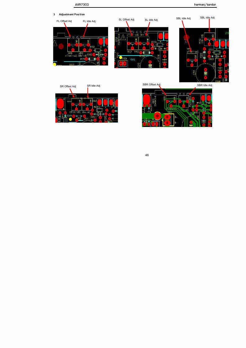
5/13/2018 AVR7300 sm - slidepdf.com
http://slidepdf.com/reader/full/avr7300-sm 46/158
3 Adjustment Position
FL Offset Adj FL Idle AdjSL Offset Adj SL Idle Adj
SBLSBL Idle Adj
SR Offset Adj SR Idle Adj SBR Offset Adj SBR I
FR Offset Adj FR Idl Adj
AVR7300 harman/

5/13/2018 AVR7300 sm - slidepdf.com
http://slidepdf.com/reader/full/avr7300-sm 47/158
4 Check Position
FR Offset Adj FR Idle Adj CT Offset Adj CT Idle Adj
FL Idle Check Position SL Idle Check Position SBL Id
SR Idl Ch k P iti SBR Idle Check Position FR Idl Ch k P iti
AVR7300 harman/k

5/13/2018 AVR7300 sm - slidepdf.com
http://slidepdf.com/reader/full/avr7300-sm 48/158
SR Idle Check Position SBR Idle Check Position FR Idle Check Position
h /k d S i B ll i
AVR7300 harman/kardon

5/13/2018 AVR7300 sm - slidepdf.com
http://slidepdf.com/reader/full/avr7300-sm 49/158
harman/kardon Service Bulletin Service bulletin # HK2005-01 January 2005 Warranty labor rate: MINOR repair
To: All harman/kardon Service Centers
Model: AVR7300
Subject: A-BUS Output too High
In the event you receive an AVR7300 with the complaint: “ There is distortion when using the A-BUS
connection and a harman/kardon AB-1”, perform the following modification:
Synopsis: Change two resistors in the AVR7300.
The actual symptom is that the AB-1 is not able to totally reduce the volume down even at the minimumposition on the level control, so there is distortion, or low level audible bleed-through in Zone 2
1) Remove the top cover (18) Black & Plated Phillips screws at the sides and rear of the unit.2) Remove the Tuner Module from the rear panel, two screws. It does not have to be disconnected.3) Removal of the DSP PCB: there are seven screws on the rear panel; four plated screws that attach the
PCB, six molex and ribbon connectors, and three connector PCB’s must be pushed away from the DSPconnectors. Remove the DSP board from the unit.
4) Removal of the Processor PCB: there are six screws on the rear panel; four standoff’s that attach the
PCB, eight molex connectors and three connector PCB’s must be pushed away from the Processor connectors. Remove the Processor board.
5) Locate the two 1KΩ 1/16W SMD resistors R249 and R205 on the bottom of the Processor board; replaceboth with 2.7KΩ components, h/k part# RS3AD0272NA-0.
6) Replace all PCB’s, connectors, standoffs and screws in reverse order.7) Test the unit (with an AB-1).
harman/kardon
AVR7300 harman/kardon

5/13/2018 AVR7300 sm - slidepdf.com
http://slidepdf.com/reader/full/avr7300-sm 50/158
harman/kardon TECH TIPS
Troubleshooting tips and solutions to common service problems
For models:
AVR7000/7200/7300/8000AVR100/200/300/500AVR110/210/310/510AVR120/220/320/520AVR125/225/325/525AVR130/230/330/430/630AVR135/235/335/435/635
AVR10DPR1001DPR1005DPR2005HK3370/3470/3375/3475HK3250
TIP# HKTT2003-01 Rev3
Subject: Backup Memory on AVR/DPR/HK series receivers
In the event of the complaint: “the receiver is losing its memory (any programmed system settings)when the unit is turned off, or after the unit is unplugged (briefly*)”:
Check and replace:
Model Designator Location Description Part number
AVR10C712D709
Front PCB0.047 Farad 5.5v capacitor and 1N4148 diode
#3439247315#2058322101
AVR7000 C730 Front PCB 0.047 Farad 5.5v capacitor # 55134360 or # J3432147324X
AVR7200 C106 Front PCB 0.047 Farad 5.5v capacitor # 55134360AVR7300 C657 DSP PCB 0.047 Farad 5.5v capacitor # H01-CEZXA0479MN-5
AVR7300 Electrical Parts List
AVR7300 harman/kardon

5/13/2018 AVR7300 sm - slidepdf.com
http://slidepdf.com/reader/full/avr7300-sm 51/158
Ref Designator Part Number Description
MAIN PCB
Capacitors
C220 223 226 CEHDC0108NN-3 CE 1MI0F +20% 6.3V 8X11.5 85C ELITE
C339 344 369 CEHEC01075E-8 CE 100U0F +20% 10.0V 5X11 85C P5MM
C1 3 311 313 320 321 324 CEHEC02275E-9 CE 220UF +20% 10.0V D6.3XL11 P5MM 85C
C2 5 7 305 307 309 314 316 318 357 361
363CEHFC01075E-1 CE 100UF +20% 16.0V D6.3XL11 P5MM 85C
C364 CEHFC04765E-3 CE47UF +20% 16.0V D5XL11 P5MM 85C
C213 216 219 222 225 228 231 232 341
352CEHIC01055E-6 CE 1UF +20% 50V D5XL11 P5MM 85C
C9 214 217 229 370 CEHIC01065E-4 CE 10U0F +20% 50.0V 85C P5MM 5X11
C10 368 CEHIC02255E-7 CE 2U2F +20% 50V D5XL11 P5MM 85C
C347 CEHIC0474NN-9 CE 470N0F +20% 50.0V 85C 5X11 ELITE
C243 CEMFA02285E-5 CE 2200UF 16V M 12.5X20 P5MM
C237 CEMFC03375E-A CE 330UF 16V M 8X11.5 P5MM 85C
C312 322 323 330 H01-CEMFC0106AH-7 CAP ELEC 10UF 16V M 5X11 P5MM SHL
C15 51 52 53 CEMFC0226NN-9 CAP ELEC 22UF 16V M ELITE
C233 235 CEMGC0227NN-0 CAP ELEC 220UF 25V M 8X11.5 ELITE
C338 CPIIC0223NN-4 CPF 22N0F +10% 50.0V
C201 202 203 204 205 206 207 208 209 CPIKC0473NN-0 CPF 47N0F +10% 100.0V
C342 CPIIC0682NN-5 CPF 6N8F +10% 50.0V
C348 349 350 351 CCJIC0390NE-2 CC 39P0F +5% -5% 50.0V NP0C261 H01-CEMIC0105AH-7 CE 1UF 50V M 5X11 SHL
C358 H01-CEMIC0334AH-4 CAP ELEC 0.33UF M 5X11 SHL 50V SAMYOUNG
C242 H01-CEMFA0109AH-6 CE MHA 10MI0F 16V M 16*35.5 SAMYOUN
C240 241 H01-CEMHA0828AH-8 CAP ELEC 8200UF 35V M 22X45 AHS SAMYOUNG
C244 H01-CEMIA0478AH-7 CAP ELEC 4700UF 50V M 22X45 DL SAMYOUNG
C238 239 H01-CEMKA0228AH-0 CAP ELEC 2200UF 100V M 22X45 AHS SAMYOUNG
C251 255 281 282 283 284 285 286 287
288 290 291 292 293 294 295 296 298 301
302 303 353 354 355
CZJII0101BE-2 CCCFMIC 100P0F +5% -5% 50.0V NP0 0603
Ref Designator Part Number Description
AVR7300 harman/kardon

5/13/2018 AVR7300 sm - slidepdf.com
http://slidepdf.com/reader/full/avr7300-sm 52/158
MAIN PCB
D5 6 7 219 220 3 4 231 232 H01-DS1S50094NB-A D-SLP 1SS355 35.0V 225MI0A
Q4 215 216 222 H01-TRDTA114YNI-9 TR-SSD DTA114YKA P 10K0 OHM 47K0 OHM
Q1 2 201 202 203 204 H01-TRDTC114YNI-5 TR-SSD DTC114YKA N 10K0 OHM 47K0 OHM
Q5 H01-TR2SA1145NA-2 TR-SLPLF 2SA1145Y TO-92MOD P -50MI0A -150V
IC208 H01-ICBU4094BD3-2 IC CMOS BU4094BF SOP16
IC209 H01-ICLC74763I4-1 IC OSD LC74763M SOP30
IC2 201 202 203 H01-ICMM1510XDL-7 IC-VIDEO SW MM1510XNRE SOT-26A
IC1 204 205 H01-ICMM1501XDL-A IC-VIDEO SW MM1501XNRE SOT-26B
IC206 H01-ICMM1511XDL-8 IC-VIDEO SW MM1511XNRE SOT-26B
Q212 H01-TRDTC114YNI-5 TR-SSD DTC114YKA N 10K0 OHM 47K0 OHM
Q3 221 H01-TRKTA1504ND-7 TRANSISTOR PNP KTA1504Y(S)SOT-23
D8 9 H01-DR1N04004NA-1 D-SR 1N4004 400.0V 1.0A
Resistors
R18 RC3DI0220IN-3 RESISTOR CARBON FILM 22OHM 1/4W 5%
R13 RC3DI022AIN-2 RCF 2R2 OHM +5% 250MI0W
R201 202 204 207 H01-RM3GC047ACN-9 RESISTOR METAL OXIDE 4R7 +5% 2.0W
R208 209 H01-RM3HA056ADN-A RESISTOR METAL OXIDE 5R6 3W 5% RW
R19 H01-RP3NA0101NZ-3 POS 100R0 OHM 16.0V RED
R12 278 281 282 283 284 285 286 287 288
291 292 293 294RS3AD0101NA-5 RMGCFMIC 100R0 OHM +5% 62MI5W
R232 RS3AD0102NA-3 RMGCFMIC 1K0 OHM +5% 62MI5W
R9 10 11 14 220 223 225 271 272 273 274 RS3AD0103NA-1 RMGCFMIC 10K0 OHM +5% 62MI5W
R15 17 RS3AD0104NA-A RMGCFMIC 100K0 OHM +5% 62MI5W
R250 251 RS3AD0105NA-8 RES CHIP 1M 1/16W +-5% 0603
R248 249 RS3AD0121NA-A RMGCFMIC 120R0 OHM +5% 62MI5W
R210 211 RS3AD0562NA-2 RMGCFMIC 5K6 OHM +5% 62MI5W
R261 265 RS3AD0392NA-1 RMGCFMIC 3K9 OHM +5% 62MI5W
R260 264 RS3AD0471NA-5 RMGCFMIC 470R0 OHM +5% 62MI5W
R266 RS3AD0473NA-1 RMGCFMIC 47K0 OHM +5% 62MI5W
R16 RS3AD0272NA-0 RMGCFMIC 2K7 OHM +5% 62MI5W
R221 222 224 RS1AD0750NA-6 RES CHIP 75OHM 1% 1/16W 0603
S GC C O %
Ref Designator Part Number Description
AVR7300 harman/kardon

5/13/2018 AVR7300 sm - slidepdf.com
http://slidepdf.com/reader/full/avr7300-sm 53/158
MAIN PCB
L213 H01-LAINB056ACR-0 LF 5U60H +10% 5.8 OHM 500MI0A
N203 204 H01-WG04SD82300-6 WIRE ASS'Y 2.5MM 4P 230MM UL1007#22 RED
N211 H01-WG15SB82800-0 WIRE ASS'Y 2.0MM 15P 280MM UL1007#26 RED
P212 H01-WH20SC00000-3 PIN HEADER 2.54MM 20P TPH03-115-20P
P211 H01-WH30SC00000-A PIN HEADER 2.54MM 30P TPH03-115-30P
N3 H01-WN02SB00000-9 CONN 2.0MM 2 MA ST NAT GT201-2P-TS
N4 H01-WN03SB00000-6 CONN 2.0MM 3 MA ST NAT GT201-3P-TS
P201 202 H01-WN06SD100WH-8 CONN WAFER 2.5MM 6P 5267-06A WHT
R203 206 H01-RM3FC010ABN-8 RESISTOR METAL OXIDE 1 OHM 1W 5%
P205 H01-WN14SB100WH-1 CONN WAFER 2.0MM 14P 35336-1410 WHT
P203 208 H01-WN19SB00000-6 CONN 2.0MM 19 MA ST NAT MOLEX 35336-1910 0 0
JA204 H01-ZVD05FAN100-8 DC FAN TFD-4510L12B 45X45X10MM
Y201 H01-OSXBE14M3AU-7 CRYSTAL 14.31818MHz WOOIN
Y202 H01-OSXBE17M7AU-9 CRYSTAL 17.734475MHz WOOIN
RY1 2 203 204 205 206 H01-RLL0517811A-A RELAY D3009(1-1462033-4)G201 H01-ZNMSA4004SN-4 TERMLUG GND
W350 H01-WG01S011000-9 WIRE ASS'Y UL1007#16 STR 110MM 1P BLK TERMINAL
F200 201 202 203 204 205 206 207 H01-FURN2200006-6 FUSE T 2A 250V 7.6X8.6 SS-5 SAVE FUSETECH
Processor PCB
Capacitors
C176 177 CEHDC0108NN-3 CE 1MI0F +20% 6.3V 8X11.5 85C ELITEC5 8 15 18 39 42 55 58 74 77 78 81 86 89
92 95 96 97 98 99 100 101 102 103 104
105 108 109 112 119 120 122 127 129 132
133 138 145 146 153 158 165 168 175 189
201 202 208 209 210 224 225 233
CEHFC04765E-3 CE47UF +20% 16.0V D5XL11 P5MM 85C
C221 222 CEHIC04755E-6 CE 4U7F +20% 50.0V 85C P5MM
C6 7 13 14 16 17 19 20 37 38 40 41 53 54
56 57 59 60 75 76 79 80 82 83 84 85 87 88
Ref Designator Part Number Description
AVR7300 harman/kardon

5/13/2018 AVR7300 sm - slidepdf.com
http://slidepdf.com/reader/full/avr7300-sm 54/158
Processor PCB
IC10 H01-ICTC9273NDA-0 IC-SWITCH TC9273F-004 SOP28 ANALOG SWITCH
Q54 H01-TRDTC114YNI-5 TR-SSD DTC114YKA N 10K0 OHM 47K0 OHM
Q24 26 27 28 29 30 31 33 36 38 39 40 42
44 45 46H01-TRKTD1304ND-5 TR-SLPSWA KTD1304 N 20V 300MI0A SOT-23
D8 9 12 14 21 Q47 H01-DSUDZ09V1NB-7 D-ZENER UDZS 9.1B 9.1V 200MI0W
IC5 14 H01-ICKIC9162DA-5 IC-SWITCH KIC9162AF SOP28 ANALOG SWITCH
IC3 H01-ICKIC9163DA-7 IC-SWITCH KIC9163AF SOP28 ANALOG SWITCH
IC2 18 H01-ICKIC9459D5-8 IC-LOWFREQ KIC9459F SOP24 TONE/VOL/BAL/MUTE
IC1 4 7 8 9 11 12 13 15 16 17 20 21 22 23
24 25 26 27H01-ICLM02068D2-A IC-OPERAMP NJM2068M DUAL SOP8
IC19 H01-ICLMO9482DA-5IC-LOWFREQ KIC9482F/TC9482F SOP28
TONE/VOL/BAL/MUTE
IC6 H01-ICTC9273NDA-0 IC-SWITCH TC9273F-004 SOP28 ANALOG SWITCH
IC28 H01-ICTC9481FDA-0 IC-LOWFREQ TC9481F SOP28 TONE
Q3 13 14 17 20 23 25 32 34 35 37 41 43 5052
H01-TRDTA114YNI-9 TR-SSD DTA114YKA P 10K0 OHM 47K0 OHM
Q22 H01-TRDTC114YNI-5 TR-SSD DTC114YKA N 10K0 OHM 47K0 OHM
Q7 8 9 10 11 12 15 16 51 53 58 59 H01-TRKTD1304ND-5 TR-SLPSWA KTD1304 N 20V 300MI0A SOT-23
Resistors
R329 334 800 RS3AD0000NA-0 RMGCFMIC 0 OHM +0% 62MI5W
R1 10 11 13 18 30 31 44 63 64 75 77 78 79
82 88 89 98 101 106 107 112 121 126 131
133 136 137 141 142 166 167 171 172 174184 185 189 195 198 204 231 238 288
RS3AD0101NA-5 RMGCFMIC 100R0 OHM +5% 62MI5W
R61 71 72 80 81 91 92 93 94 95 96 138
139 140 143 144 145 150 151 152 153 154
155 168 169 170 205 221 229 247 249 254
256 264 269 277 279 286 293 301 303 310
315 316 324 325 326 343 344 345 346 347
348 349 350 378
RS3AD0102NA-3 RMGCFMIC 1K0 OHM +5% 62MI5W
R2 5 12 14 15 16 17 21 26 28 33 35 40 41
Ref Designator Part Number Description
AVR7300 harman/kardon

5/13/2018 AVR7300 sm - slidepdf.com
http://slidepdf.com/reader/full/avr7300-sm 55/158
Processor PCB
R322 323 376 377 RS3AD0100NA-7 RMGCFMIC 10R0 OHM +5% 62MI5W
R232 242 243 253 280 290 304 314 RS3AD0101NA-5 RMGCFMIC 100R0 OHM +5% 62MI5W
R122 125 RS3AD0102NA-3 RMGCFMIC 1K0 OHM +5% 62MI5W
R90 RS3AD0104NA-A RMGCFMIC 100K0 OHM +5% 62MI5W
R135 158 RS3AD0123NA-6 RMGCFMIC 12K0 OHM +5% 62MI5W
R223 262 271 295 RS3AD0183NA-A RMGCFMIC 18K0 OHM +5% 62MI5W
R7 8 23 24 37 38 53 54 224 228 257 261
272 276 296 300 330 333RS3AD0222NA-4 RMGCFMIC 2K2 OHM +5% 62MI5W
R156 157 159 160 RS3AD0332NA-8 RMGCFMIC 3K3 OHM +5% 62MI5W
R19 55 83 84 87 219 265 266 267 291 RS3AD0333NA-6 RMGCFMIC 33K0 OHM +5% 62MI5W
R182 RS3AD0471NA-5 RMGCFMIC 470R0 OHM +5% 62MI5W
R320 321 341 342 RS3AD0472NA-3 RMGCFMIC 4K7 OHM +5% 62MI5W
R227 258 275 299 331 RS3AD0474NA-A RMGCFMIC 470K0 OHM +5% 62MI5W
R197 RS3AD0220NA-8 RMGCFMIC 22R0 OHM +5% 62MI5W
R209 210 RS3AD0153NA-8 RES CHIP,15K 1/16W,+-5%,0603.R318 RC3DI0100IN-2 RCF 10R0 OHM +5% 250MI0W
R97 208 RC3DI0153IN-3 RCF 15K0 OHM +5% 250MI0W
Miscellaneous
SK1 H01-RLL1296122A-5 RELAYSGNL 12.0V 960.0OHM 3.0A
NJ51 52 53 54 H01-SORA40GNDNN-7 JACK RCA 4P JB040131PN WWRR
NJ55 H01-SORA64105NN-5 JACK RCA 6P JB060132PN
P516 H01-WG04SB81100-3 WIRE ASS'Y DL 2.0MM 4P 110MM UL1007 #26 RED
P508 H01-WN03SD100WH-6 CONN WAFER 2.5MM 3P 5267-03A WHT
P2 517 H01-WN04AB100WH-8 CONN WAFER 2.0MM 4P 35237-0410 WHT
P513 H01-WN04SB00000-3 CONN 2.0MM 4 MA ST NAT GT201-4P-TS
P507 512 H01-WN04SD100WH-3 CONN WAFER 2.5MM 4P 5267-04A WHT
P506 511 H01-WN05SD100WH-0 CONN WAFER 2.5MM 5P 5267-05A WHT
P505 H01-WN06SD100WH-8 CONN WAFER 2.5MM 6P 5267-06A WHT
P510 H01-WN07SD00000-3 CNT PLUG ST 2.5mm 7P 5267-07A
P503 H01-WN14AB100WH-4 CONN WAFER 2.0MM 14P 35237-1410 WHT
P504 H01-WN15SI00000-0 CONN FFC 1.25MM 15P SCB-1115-00-2 VER
P509 H01-WN19AB00000-9 CONN 2.0MM 19 MA R NAT SOCKET MOLEX 35237-1910 0 0
Ref Designator Part Number Description
AVR7300 harman/kardon
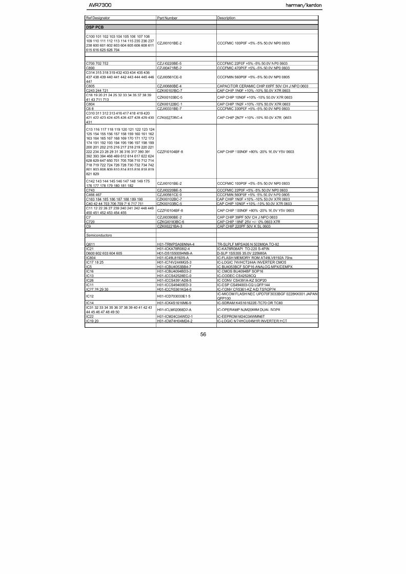
5/13/2018 AVR7300 sm - slidepdf.com
http://slidepdf.com/reader/full/avr7300-sm 56/158
DSP PCB
C100 101 102 103 104 105 106 107 108
109 110 111 112 113 114 115 235 236 237
238 600 601 602 603 604 605 606 608 611
615 616 625 626 704
CZJII0101BE-2 CCCFMIC 100P0F +5% -5% 50.0V NP0 0603
C700 702 752 CZJII0220BE-5 CCCFMIC 22P0F +5% -5% 50.0V NP0 0603
C890 CZJII0471BE-2 CCCFMIC 470P0F +5% -5% 50.0V NP0 0603
C314 315 318 319 432 433 434 435 436
437 438 439 440 441 442 443 444 445 446
447
CZJII0561CE-0 CCCFMIN 560P0F +5% -5% 50.0V NP0 0805
C805 CZJII0680BE-4 CAPACITOR CERAMIC CHIP 68PF 50V CH J NPO 0603
C243 244 721 CZKII0102BC-7 CAP CHIP 1N0F +10% -10% 50.0V X7R 0603
C18 19 20 21 24 25 32 33 34 35 37 38 39
41 43 711 713CZKII0103BC-5 CAP CHIP 10N0F +10% -10% 50.0V X7R 0603
C804 CZKII0122BC-1 CAP CHIP 1N2F +10% -10% 50.0V X7R 0603
C6 8 CZJII0331BE-7 CCCFMIC 330P0F +5% -5% 50.0V NP0 0603
C310 311 312 313 416 417 418 419 420
421 422 423 424 425 426 427 428 429 430
431
CZKII0272BC-4 CAP CHIP 2N7F +10% -10% 50.0V X7R 0603
C13 116 117 118 119 120 121 122 123 124
125 154 155 156 157 158 159 160 161 162
163 164 165 167 168 169 170 171 172 173
174 191 192 193 194 195 196 197 198 199
200 201 202 215 216 217 218 219 220 221222 234 23 28 29 31 36 316 317 390 391
392 393 394 468 469 612 614 617 622 624
628 629 647 650 701 705 708 710 712 714
718 719 722 724 726 728 730 732 734 742
801 803 808 809 810 814 815 816 818 819
821 829
CZZFI0104BF-8 CAP CHIP 100N0F +80% -20% 16.0V Y5V 0603
C142 143 144 145 146 147 148 149 175
176 177 178 179 180 181 182CZJII0101BE-2 CCCFMIC 100P0F +5% -5% 50.0V NP0 0603
Ref Designator Part Number Description
DSP PCB
AVR7300 harman/kardon

5/13/2018 AVR7300 sm - slidepdf.com
http://slidepdf.com/reader/full/avr7300-sm 57/158
DSP PCB
IC24 H01-ICMM1662HI3-2 IC MM1662H LOW DROP VOLTAGE REGULATOR SOP-8
IC23 H01-ICNJU6324D2-3 IC-SPECFUNC NJU6324M SOP8 CMOS CRYSTAL
Q600 601 604 605 606 607 608 609 612
613H01-TRDTC114YNI-5 TR-SSD DTC114YKA N 10K0 OHM 47K0 OHM
D601 H01-DS1S50094NB-A D-SLP 1SS355 35.0V 225MI0A
Q402 403 H01-TRDTA114YNI-9 TR-SSD DTA114YKA P 10K0 OHM 47K0 OHM
Q400 401 H01-TRKTD1304ND-5 TR-SLPSWA KTD1304 N 20V 300MI0A SOT-23
Resistors
R735 RS3AD0391NA-3 RMGCFMIC 390R0 OHM +5% 62MI5W
R619 RC3DI010AIN-1 RCF 1R0 OHM +5% 250MI0W
R22 RC3DI0560IN-1 RCF 56 OHM +5% 250MI0W
R23 RC3DI022AIN-2 RCF 2R2 OHM +5% 250MI0W
R27 28 29 30 715 RS3AD0101NA-5 RMGCFMIC 100R0 OHM +5% 62MI5WR100 101 102 103 104 106 107 701 RS3AD0102NA-3 RMGCFMIC 1K0 OHM +5% 62MI5W
R180 181 182 183 184 185 186 187 238
239 242 243 621 654 741 753 756 802RS3AD0103NA-1 RMGCFMIC 10K0 OHM +5% 62MI5W
R140 141 142 143 144 145 146 147 315
316 448 449 450 451 452 453 454 470 471RS3AD0104NA-A RMGCFMIC 100K0 OHM +5% 62MI5W
R305 306 307 308 416 417 418 419 420
421 422 423 424 425 426 427 428 429 430
431
RS3AD0122NA-8 RMGCFMIC 1K2 OHM +5% 62MI5W
R132 133 134 135 136 137 138 139 196
197 198 199 200 201 202 203 246 247RS3AD0151NA-1 RMGCFMIC 150R0 OHM +5% 62MI5W
R799 RS3AD0200NA-3 RES,CHIP 20 OHM 1/16W +/-5% 0603
R234 235 RS3AD0203NA-8 RMGCFMIC 20K0 OHM +5% 62MI5W
R24 RS3AD0221NA-6 RMGCFMIC 220R0 OHM +5% 62MI5W
R870 RS3AD0302NA-6 RMGCFMIC 3K0 OHM +5% 62MI5W
R744 876 877 878 RS3AD0332NA-8 RMGCFMIC 3K3 OHM +5% 62MI5W
R400 401 402 403 404 405 406 407 408RS3AD0432NA 4 RMGCFMIC 4K3 OHM +5% 62MI5W
Ref Designator Part Number Description
DSP PCB
AVR7300 harman/kardon

5/13/2018 AVR7300 sm - slidepdf.com
http://slidepdf.com/reader/full/avr7300-sm 58/158
DSP PCB
R725 736 738 752 RS3AD0222NA-4 RMGCFMIC 2K2 OHM +5% 62MI5W
R2 875 RS3AD0332NA-8 RMGCFMIC 3K3 OHM +5% 62MI5W
R25 710 722 RS3AD0471NA-5 RMGCFMIC 470R0 OHM +5% 62MI5W
R18 19 20 RS3AD0472NA-3 RMGCFMIC 4K7 OHM +5% 62MI5W
R15 702 706 724 727 737 739 751 755 RS3AD0473NA-1 RMGCFMIC 47K0 OHM +5% 62MI5W
R709 721 RS3AD0511NA-8 RMGCFMIC 510R0 OHM +5% 62MI5W
R468 469 704 717 726 743 RS3AD0561NA-4 RMGCFMIC 560R0 OHM +5% 62MI5W
R723 RS3AD0750NA-1 RMGCFMIC 75R0 OHM +5% 62MI5W
R625 RS3AD0822NA-2 RMGCFMIC 8K2 OHM +5% 62MI5W
RX21 23 25 26 27 RS3AY0103NA-7 RCA 10K0 OHM +5% 62M15W 4
RX22 24 RS3AY0332NA-3 RCA 3K3 OHM +5% 62M15W 4
RX11 12 13 14 15 16 17 18 19 RS3AY0470NA-2 RCA 47R0 OHM +5% 62M15W 4
R11 13 745 746 RS3AD0221NA-6 RMGCFMIC 220R0 OHM +5% 62MI5W
Miscellaneous
L2 3 4 5 H01-LAINB0470CR-2 LF 47U0H +10% 5.8 OHM 500MI0A
L600 H01-LAINB047ACR-3 LF 4U7H +10% 1.7 OHM 190.0A
L100 101 102 103 104 105 106 107 108
109 110 111 706 712 714 804 805 R879H01-FB3002012NN-4 FBEAD SURFACE MT 300OHM FCM2012V-301T07
L112 113 114 18 703 707 710 711 800 802
803H01-FB3002012NN-4 FBEAD SURFACE MT 300OHM FCM2012V-301T07
L700 H01-FB2K52012NN-5 FBEAD SURFACE MT 2500OHM FCM2012H-252T02
TF11 12 H01-LF11030A2NA-4 TFPULSE TRANSFORMER 110UH FP-110 FERRIT MAGNET
Y800 H01-OSCEM24M5RU-A VCXO 24M576 HZ +50 PPM -50 PPM 0 OHM 3.3V
Y600 H01-OSCNI20MOCU-6 CSTLS20MOX51-B0
NJ12 H01-SORA40RSANN-6 JACK RCA 4P JB040131ZN GN BN PP TA
NJ11 H01-SORA40RSCNN-A JACK RCA 4P JB040131QN WH BU RD GY
NJ14 15 16 H01-SOTOR179LBA-0 D-LEM TORX-179L
NJ17 H01-SOTOT179LBA-7 D-LEM TOTX-179L
N105 H01-WG09SB83000-A WIRE ASS'Y 2.0MM 9P 300MM UL1007#26 WHT
Ref Designator Part Number Description
3 CHANNEL AMP
AVR7300 harman/kardon

5/13/2018 AVR7300 sm - slidepdf.com
http://slidepdf.com/reader/full/avr7300-sm 59/158
3 CHANNEL AMP
C109 110 111 112 209 210 211 212 309
310 311 312H01-CEMKA0127AH-0 CAP ELEC 120UF 100V M 12X16 AHS
Semiconductors
D907 H01-DZ1N05231NB-1 D-ZENER 1N5231B 5.1V 500MI0W
D107 207 307 H01-DR1N04004NA-1 D-SR 1N4004 400.0V 1.0A
D101 104 105 108 201 204 205 208 301
304 305 308 901 902 908 909 910H01-DG1N04148NB-4 D-SLP 1N4148 100.0V 150E-3A
D102 103 202 203 302 303 H01-DR01SS244NA-2 DIODE 1SS244 220V
Q926 927 928 H01-TR2SC1740NW-9 TR-SLPLF 2SC1740S R N 150MI0A 50V
Q901 H01-TRKTA1024NA-7 TR-SLPLF KTA1024 Y P 50MI0A -150V
Q925 H01-TRKTA1266NA-0 TR-SLPLF KTA1266 Y P 150MI0A
Q107 207 307 H01-TRKTA1268NA-4 TR-SHPLF KTA1268BL P 100MI0A 120V
Q105 123 205 223 305 323 H01-TRKTC3198NA-3 TR-SLPLF KTC3198BL N 150MI0AQ101 102 103 104 122 201 202 203 204
222 301 302 303 304 322H01-TRKTC3200NA-9 TR-SHPLF KTC3200BL N 100MI0A 120V
Q902 H01-TRDTC114YNW-6 TR-SLPLF DTC114YSA N 100MI0A
Q108 109 116 208 209 216 308 309 316 H01-TR2SA1360BC-6 TRANSISTOR PNP 2SA1360-Y 50MI0A -150V
Q106 206 306 H01-TR2SA1370BC-7 TRANSISTOR PNP 2SA1370-E 100MI0A 40 320
Q115 215 315 H01-TR2SA1859BC-2 TR-SHPLF 2SA1859A P -2.0A
Q120 121 220 221 320 321 H01-TR2SA1943RP-A TRANSISTOR PNP 2SA1943-O TO-220
Q110 111 114 210 211 214 310 311 314 H01-TR2SC3423BC-0 TRANSISTOR NPN 2SC3423-Y 50MI0A 150V
Q112 212 312 H01-TR2SC4137BE-0 TR-SHPLF 2SC4137 N 100MI0A 20V
Q117 217 317 H01-TR2SC4883BC-8 TR-SHPLF 2SC4883A N 2.0A
Q118 119 218 219 318 319 H01-TR2SC5200RP-6 TRANSISTOR NPN 2SC5200-O TO-220
Resistors
R138 139 238 239 338 339 H01-RM3FC022ANN-0 RESISTOR METAL OXIDE 2R2 OHM 1W 5%
R106 107 108 206 207 208 306 307 308 RC3DI0101IN-0 RCF 100R0 OHM +5% 250MI0W
Ref Designator Part Number Description
3 CHANNEL AMP
AVR7300 harman/kardon

5/13/2018 AVR7300 sm - slidepdf.com
http://slidepdf.com/reader/full/avr7300-sm 60/158
3 CHANNEL AMP
R136 137 236 237 336 337 H01-RM3EG0150LN-4 RESISTOR METAL OXIDE 15 OHM 1/2W 5%
R132 133 232 233 332 333 H01-RM3EG022ALN-0 RESISTOR METAL OXIDE 2R2 OHM 1/2W 5%
R110 210 310 H01-RM3EG0820LN-9 RESISTOR METAL OXIDE 82 OHM 1/2W 5%
R113 213 313 H01-RC1QC2671IN-6 RES CARBON FILM 2K67 OHM 1/5W 1%
R130 131 230 231 330 331 H01-RM3FC0560BN-5 RESISTOR METAL OXIDE 56 OHM 1W 5%R171 172 271 272 371 372 H01-RI3IC022BEN-8 RW 220MI0 OHM +5% 5.0W 100PPM/'C -100PPM/'C
Miscellaneous
B101 102 103 104 201 202 203 204 301
302 303 304H01-FB44HM15300-4 LF BEADS 44.1530HM 100MHZ FB-30 HC-3550
G302 303 H01-ZNMSA4004SN-4 TERMLUG GND
N309 H01-WG03SE83800-8WIRE ASS'Y 3.96MM 3P 160/300/380MM UL1007#16 STR
BLU
N310 H01-WG03SE83700-6 WIRE ASS'Y 3.96MM 3P 140/260/370MM UL1007#16 STRRED
L101 201 301 H01-LCNNNA050NA-1 LFA 1MM 10MM 5 LEFT 0.0MM NONE
SK11 21 31 H01-RL1K124V05A-2 RELAY SGNL OMI-SS-224L 1K1 OHM 24V 5A
R161 261 361 H01-RM3GC0100CN-7 RESISTOR METAL OXIDE 10R0 OHM +5% 2.0W
RV12 22 32 H01-RT7EA0201NB-6 PR 200R0 OHM +20% 500MI0W
RV11 21 31 H01-RT7EA0500NB-9 PR 50R0 OHM +20% 500MI0W
NJ33 H01-SOSP20117NN-6 JACK SPEAKER 2P B30290117N BK/WH
NJ32 H01-SOSP20118NN-8 JACK SPEAKER 2P B30290118N BK/BU
NJ31 H01-SOSP20119NN-A JACK SPEAKER 2P B30290119N BK/BRN
N312 H01-WG02SE82500-4 WIRE ASS'Y 3.96MM 2P 170/250MM UL1007#18 BLU
P702 H01-WG02SE852BK-9 WIRE ASS'Y 3.96MM 2P 520MM UL1007#16 BLK
N704 H01-WG02SE852RD-7 WIRE ASS'Y 3.96MM 2P 520MM UL1007#16 RED
N311 H01-WG03SE82000-2 WIRE ASS'Y 3.96MM 3P 200MM UL1007#16 RED
N306 H01-WG03SE82300-8 WIRE ASS'Y 3.96MM 3P 230/200/230MM UL1007#18 WHT
P337 384 385 386 H01-WN02SD00000-7 CONN 2.5MM 2 MA ST NAT 0 0
P202 H01-WN04SD100WH-3 CONN WAFER 2.5MM 4P 5267-04A WHT
P316 317 318 H01-WN07AB100WH-A CONN WAFER 2.0MM 7P 35237-0710 WHT
P321 322 323 H01-WN07SB100WH-7 CONN WAFER 2.0MM 7P 35336-0710 WHT
Ref Designator Part Number Description
4 CHANNEL AMP
AVR7300 harman/kardon

5/13/2018 AVR7300 sm - slidepdf.com
http://slidepdf.com/reader/full/avr7300-sm 61/158
4 CHANNEL AMP
Semiconductors
D401 404 405 408 501 504 505 508 601
604 605 608 701 704 705 708 801 802
H01-DG1N04148NB-4 D-SLP 1N4148 100.0V 150E-3A
D407 507 607 707 H01-DR1N04004NA-1 D-SR 1N4004 400.0V 1.0A
Q801 H01-TRKTA1024NA-7 TR-SLPLF KTA1024 Y P 50MI0A -150V
Q407 507 607 707 H01-TRKTA1268NA-4 TR-SHPLF KTA1268BL P 100MI0A 120V
Q405 423 505 523 605 623 705 723 H01-TRKTC3198NA-3 TR-SLPLF KTC3198BL N 150MI0A
Q401 402 403 404 422 501 502 503 504
522 601 602 603 604 622 701 702 703 704
722
H01-TRKTC3200NA-9 TR-SHPLF KTC3200BL N 100MI0A 120V
Q802 H01-TRDTC114YNW-6 TR-SLPLF DTC114YSA N 100MI0A
Q408 409 416 508 509 516 608 609 616
708 709 716H01-TR2SA1360BC-6 TRANSISTOR PNP 2SA1360-Y 50MI0A -150V
Q406 506 606 706 H01-TR2SA1370BC-7 TRANSISTOR PNP 2SA1370-E 100MI0A 40 320
Q415 515 615 715 H01-TR2SA1859BC-2 TR-SHPLF 2SA1859A P -2.0A
Q420 421 520 521 620 621 720 721 H01-TR2SA1943RP-A TRANSISTOR PNP 2SA1943-O TO-220
Q410 411 414 510 511 514 610 611 614
710 711 714H01-TR2SC3423BC-0 TRANSISTOR NPN 2SC3423-Y 50MI0A 150V
Q412 512 612 712 H01-TR2SC4137BE-0 TR-SHPLF 2SC4137 N 100MI0A 20V
Q417 517 617 717 H01-TR2SC4883BC-8 TR-SHPLF 2SC4883A N 2.0A
Q418 419 518 519 618 619 718 719 H01-TR2SC5200RP-6 TRANSISTOR NPN 2SC5200-O TO-220
D402 403 502 503 602 603 702 703 H01-DR01SS244NA-2 DIODE 1SS244 220V
Resistors
R406 407 408 506 507 508 606 607 608
706 707 708RC3DI0101IN-0 RCF 100R0 OHM +5% 250MI0W
R401 501 601 701 RC3DI0102IN-9 RCF 1K0 OHM +5% 250MI0W
R444 445 544 545 644 645 744 745 RC3DI0122IN-3 RCF 1K2 OHM +5% 250MI0W
R420 421 422 423 520 521 522 523 620
621 622 623 720 721 722 723RC3DI0151IN-7 RCF 150 OHM 5% 1/4W
R403 404 503 504 603 604 703 704 RC3DI0152IN-5 RCF 1K5 OHM +5% 250MI0W
Ref Designator Part Number Description
4 CHANNEL AMP
AVR7300 harman/kardon

5/13/2018 AVR7300 sm - slidepdf.com
http://slidepdf.com/reader/full/avr7300-sm 62/158
C
VR42 52 62 72 H01-RT7EA0201NB-6 PR 200R0 OHM +20% 500MI0W
VR41 51 61 71 H01-RT7EA0500NB-9 PR 50R0 OHM +20% 500MI0W
Miscellaneous
G401 501 601 701 802 H01-ZNMSA4004SN-4 TERMLUG GND
L401 501 601 701 H01-LCNNNA050NA-1 LFA 1MM 10MM 5 LEFT 0.0MM NONE
SK41 51 61 71 H01-RL1K124V05A-2 RELAY SGNL OMI-SS-224L 1K1 OHM 24V 5A
NJ51 H01-SOSP20115NN-2 JACK SPEAKER 2P B30290115N GY/BK D/N
NJ61 H01-SOSP20116NN-4 JACK SPEAKER 2P B30290116N TAN/BK
NJ41 H01-SOSP40164NN-1 JACK SPEAKER 4P B30490164N GN/BK/R/B
P1 2 3 4 5 6 H01-WE01S7065BK-4 WIRE ASS'Y DIA1.5MM 1P 70MM TUBE L=65MM BLK
N703 H01-WG02SE81200-8 WIRE ASS'Y 3.96MM 2P 120MM UL1007#18 RED
N801 H01-WG02SE81700-7 WIRE ASS'Y 3.96MM 2P 70/170MM UL1007#18 RED
N802 H01-WG02SE82000-5 WIRE ASS'Y 3.96MM 2P 120/200MM UL1007#18 REDN603 H01-WG02SE82400-2 WIRE ASS'Y 3.96MM 2P 240MM UL1007#18 RED
N503 H01-WG02SE83000-6 WIRE ASS'Y 3.96MM 2P 300MM UL1007#18 RED
N403 H01-WG02SE83800-0 WIRE ASS'Y 3.96MM 2P 380MM UL1007#18 RED
P702 H01-WG02SE852BK-9 WIRE ASS'Y 3.96MM 2P 520MM UL1007#16 BLK
N705 H01-WG02SE852RD-7 WIRE ASS'Y 3.96MM 2P 520MM UL1007#16 RED
N803 H01-WG04SE81800-3 WIRE ASS'Y 3.96MM 4P 180MM UL1007#16 RED
P401 501 601 701 905 H01-WN02SD00000-7 CONN 2.5MM 2 MA ST NAT 0 0
P402 H01-WN04SD100WH-3 CONN WAFER 2.5MM 4P 5267-04A WHT
P416 417 418 419 H01-WN07AB100WH-A CONN WAFER 2.0MM 7P 35237-0710 WHT
P406 506 606 706 H01-WN07SB100WH-7 CONN WAFER 2.0MM 7P 35336-0710 WHT
N406 H01-WS3262505FB-8 WIRE ASS'Y 2.5MM 3P 250MM UL2547#26 BLK SHIELD
N405 H01-WS4241813FN-4 WIRE ASS'Y 2.5MM 4P 180MM UL1007/2547 #24/26 SHIELD
N402 H01-WS5242623FN-4 WIRE ASS'Y 2.5MM 5P 260MM UL1007/2547#24/26 SHIELD
N401 H01-WS6242933FN-6 WIRE ASS'Y 2.5MM 6P 290MM UL1007/2547 #24/26 SHIELD
FRONT PCB
Ref Designator Part Number Description
FRONT PCB
AVR7300 harman/kardon

5/13/2018 AVR7300 sm - slidepdf.com
http://slidepdf.com/reader/full/avr7300-sm 63/158
R732 733 734 RC3DI0103IN-7 RCF 10K0 OHM +5% 250MI0W
R740 741 RC3DI0221IN-1 RCF 220R0 OHM +5% 250MI0W
R706 707 RC3DI033AIN-6 RCF 3R3 OHM +5% 250MI0W
R742 743 RC3DI0471IN-0 RCF 470R0 OHM +5% 250MI0W
R738 RS3AD0101NA-5 RMGCFMIC 100R0 OHM +5% 62MI5WR714 723 735 736 737 739 RS3AD0102NA-3 RMGCFMIC 1K0 OHM +5% 62MI5W
R704 705 751 RS3AD0103NA-1 RMGCFMIC 10K0 OHM +5% 62MI5W
R715 724 RS3AD0122NA-8 RMGCFMIC 1K2 OHM +5% 62MI5W
R716 725 RS3AD0152NA-A RMGCFMIC 1K5 OHM +5% 62MI5W
R722 731 RS3AD0183NA-A RMGCFMIC 18K0 OHM +5% 62MI5W
R717 726 RS3AD0222NA-4 RMGCFMIC 2K2 OHM +5% 62MI5W
R718 727 RS3AD0272NA-0 RMGCFMIC 2K7 OHM +5% 62MI5W
R719 728 RS3AD0332NA-8 RMGCFMIC 3K3 OHM +5% 62MI5W
R749 750 RS3AD0391NA-3 RMGCFMIC 390R0 OHM +5% 62MI5W
R747 748 RS3AD0471NA-5 RMGCFMIC 470R0 OHM +5% 62MI5WR720 729 RS3AD0562NA-2 RMGCFMIC 5K6 OHM +5% 62MI5W
R721 730 RS3AD0822NA-2 RMGCFMIC 8K2 OHM +5% 62MI5W
R746 RS3AD0100NA-7 RMGCFMIC 10R0 OHM +5% 62MI5W
Miscellaneous
L701 H01-LAINB047ACR-3 LF 4U7H +10% 1.7 OHM 190.0A
S701 702 703 704 705 706 707 708 709
710 711 712 713 714 715 716 717 718 719
720
H01-SWC2A112FS1-8 SWITACT VERTICAL SKQNADD010 12V 50MA
RM71 H01-ICRPM6938NN-3 IC-REMOTE RPM6938-RSIP-A3 RECEIVER 38KHZ
NJ71 H01-SORA3313PNN-3 CON PHONO SCKT RCA-313P 3 PINS
NJ72 H01-SORA8OSC5N8-2 JACK S-VIDEO 1P C40160261N
NJ88 H01-SOSS9CKX3NN-9 JACK PHONE 6.35 H70980110S 9P BK
RV71 H01-SWE3AEC11S1-8 VOLUME ENCODER EC11B20203
DP71 H01-VDHCA18LL03-7 FL HCA-18LL03
N703 704 H01-WG04SB809DN-0WIRE ASS'Y UL1007#26 STR 90MM 2.0MM 4P WHT PIN
DOWN
N702 H01-WG11SB83000-8 WIRE ASS'Y 2.0MM 11P 300MM WHT UL1007#26
S S S G G C
Ref Designator Part Number Description
POWER SUPPLY
AVR7300 harman/kardon

5/13/2018 AVR7300 sm - slidepdf.com
http://slidepdf.com/reader/full/avr7300-sm 64/158
C606 662 663 CZZFI0104BF-8 CAP CHIP 100N0F +80% -20% 16.0V Y5V 0603
Semiconductors
D449 450 451 453 454 455 456 457 465466 472 473 478 479 501 502 503 504 506
507
H01-DR1N04004NA-1 D-SR 1N4004 400.0V 1.0A
D474 475 505 H01-DZMTZJ22BNB-8 DIODE ZENER MTZ J 22B 22V 0.5W DO-34
D508 H01-DZMTZJ5B6NB-5 DIODE ZENER MTZ J5.6B 5.6V 500MW DO-34
D452 H01-DU35A3504WF-2 DIODE BRIDGE BP3504WF 35A
D458 H01-DZ1N05231NB-1 D-ZENER 1N5231B 5.1V 500MI0W
D476 H01-DZMTZ09V1NB-0 D-ZENER MTZJ 9.1V 500MI0W
IC41 47 H01-ICKIA7806I2-9 IC KIA7806AP VOLTQAGE REGULATOR TO-220AB
IC42 H01-ICKA78R05I2-9 IC VOLTAGE REGULATOR KIA78R05API TO-220IS-4
IC45 H01-ICBA033T0I2-9 IC-REGPOSFXD BA033T NORMALIC43 H01-ICUPD4721D8-3
IC-SPECFUNC UPD4721 DRIVERS/RECEIVERS CMOS RS-
232C
Q501 H01-TR2SA933ANW-2 TR-SLPLF 2SA933ASR P -3.0A -20V
Q452 453 454 455 456 460 H01-TRMPSA06NNA-4 TR-SLPLF MPSA06 N 500MI0A TO-92
Resistors
R504 RC3DI0101IN-0 RCF 100R0 OHM +5% 250MI0W
R458 RC3DI0102IN-9 RCF 1K0 OHM +5% 250MI0W
R457 RC3DI0103IN-7 RCF 10K0 OHM +5% 250MI0W
R505 RC3DI0182IN-7 RCF 1K8 OHM 5% 1/4WR461 462 467 RC3DI0330IN-7 RESISTOR CARBON FILM 33 OHM 1/4W 5%
R453 454 RC3DI0472IN-9 RCF 4K7 OHM 5% 1/4W
R448 H01-RM3FC010ABN-8 RESISTOR METAL OXIDE 1 OHM 1W 5%
R459 H01-RM3FC0120BN-9 RESISTOR METAL OXIDE 12 OHM 1W 5%
R479 480 H01-RM3FC0123BN-4 RESISTOR METAL OXIDE 12K OHM 1W 5%
R502 H01-RM3FC047ABN-9 RESISTOR METAL OXIDE 4R7 1W 5%
R476 501 H01-RM3GC0100CN-7 RESISTOR METAL OXIDE 10R0 OHM +5% 2.0W
R477 H01-RM3GC022ACN-8 RESITOR METAL OXIDE 2R2 OHM +5% 2.0W
GC C S S O O %
Ref Designator Part Number Description
POWER SUPPLY
AVR7300 harman/kardon
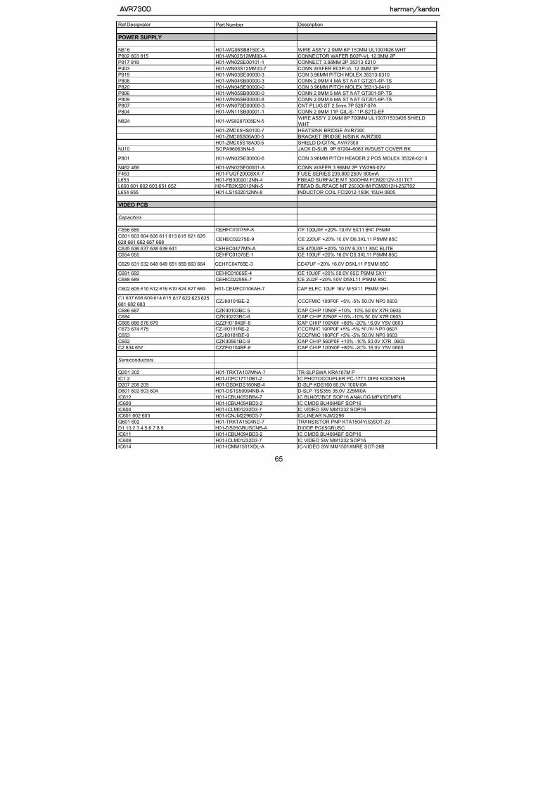
5/13/2018 AVR7300 sm - slidepdf.com
http://slidepdf.com/reader/full/avr7300-sm 65/158
N816 H01-WG06SB81500-5 WIRE ASS'Y 2.0MM 6P 150MM UL1007#26 WHT
P802 803 815 H01-WN02S12MM00-A CONNECTOR WAFER B02P-VL 12.0MM 2P
P817 818 H01-WN02SE00101-1 CONNECT 3.96MM 2P 35313-0210
P403 H01-WN03S12MM00-7 CONN WAFER B03P-VL 12.0MM 3P
P819 H01-WN03SE00000-3 CON 3.96MM PITCH MOLEX 35313-0310P808 H01-WN04SB00000-3 CONN 2.0MM 4 MA ST NAT GT201-4P-TS
P820 H01-WN04SE00000-0 CON 3.96MM PITCH MOLEX 35313-0410
P806 H01-WN05SB00000-0 CONN 2.0MM 5 MA ST NAT GT201-5P-TS
P809 H01-WN06SB00000-8 CONN 2.0MM 6 MA ST NAT GT201-6P-TS
P807 H01-WN07SD00000-3 CNT PLUG ST 2.5mm 7P 5267-07A
P804 H01-WN11SB00001-1 CONN 2.0MM 11P GIL-S-11P-S2T2-EF
N824 H01-WS8267005EN-5WIRE ASS'Y 2.0MM 8P 700MM UL1007/1533#26 SHIELD
WHT
H01-ZMD05HS0100-7 HEATSINK BRIDGE AVR7300
H01-ZMD05S06A00-5 BRACKET BRIDGE H/SINK AVR7300H01-ZMD05S18A00-5 SHIELD DIGITAL AVR7300
NJ10 SOPA96063NN-0 JACK D-SUB 9P 87204-6063 W/DUST COVER BK
P801 H01-WN02SE00000-6 CON 3.96MM PITCH HEADER 2 POS MOLEX 35328-0210
N462 466 H01-WN02SE00001-A CONN WAFER 3.96MM 2P YW396-02V
F453 H01-FUGF20008XX-7 FUSE SERIES 239.800 250V 800mA
L653 H01-FB3002012NN-4 FBEAD SURFACE MT 300OHM FCM2012V-301T07
L600 601 602 603 651 652 H01-FB2K52012NN-5 FBEAD SURFACE MT 2500OHM FCM2012H-252T02
L654 655 H01-LS1502012NN-8 INDUCTOR COIL FCI2012-150K 15UH 0805
VIDEO PCB
Capacitors
C656 685 CEHEC01075E-8 CE 100U0F +20% 10.0V 5X11 85C P5MM
C601 603 604 606 611 613 618 621 626
628 661 662 667 668CEHEC02275E-9 CE 220UF +20% 10.0V D6.3XL11 P5MM 85C
C635 636 637 638 639 641 CEHEC0477MN-A CE 470U0F +20% 10.0V 6.3X11 85C ELITE
C654 655 CEHFC01075E-1 CE 100UF +20% 16.0V D6.3XL11 P5MM 85C
Ref Designator Part Number Description
VIDEO PCB
AVR7300 harman/kardon

5/13/2018 AVR7300 sm - slidepdf.com
http://slidepdf.com/reader/full/avr7300-sm 66/158
IC605 606 607 H01-ICNJM2296D3-7 IC-LINEAR NJM2296
IC613 H01-ICTSH95IDB4-6 IC-VIDEOPROC TSH95ID VIDEO AMPLIFIER
Q603 604 H01-TRDTA114YNI-9 TR-SSD DTA114YKA P 10K0 OHM 47K0 OHM
Q611 612 613 H01-TRDTC114YNS-1 TRANSISTOR NPN DTC114YK (S) SPT/RHOM
Resistors
R636 637 638 RS3AD0102NA-3 RMGCFMIC 1K0 OHM +5% 62MI5W
R251 606 611 612 616 621 622 626 631
632RS3AD0103NA-1 RMGCFMIC 10K0 OHM +5% 62MI5W
R639 RS3AD0123NA-6 RMGCFMIC 12K0 OHM +5% 62MI5W
R673 674 RS3AD0222NA-4 RMGCFMIC 2K2 OHM +5% 62MI5W
R651 RS3AD0223NA-2 RMGCFMIC 22K0 OHM +5% 62MI5W
R247 RS3AD0271NA-2 RMGCFMIC 270R0 OHM +5% 62MI5W
R646 RS3AD0331NA-A RMGCFMIC 330R0 OHM +5% 62MI5WR671 675 RS3AD0333NA-6 RMGCFMIC 33K0 OHM +5% 62MI5W
R240 RS3AD0392NA-1 RMGCFMIC 3K9 OHM +5% 62MI5W
R244 248 RS3AD0470NA-7 RMGCFMIC 47R0 OHM +5% 62MI5W
R246 RS3AD0471NA-5 RMGCFMIC 470R0 OHM +5% 62MI5W
R242 243 RS3AD0473NA-1 RMGCFMIC 47K0 OHM +5% 62MI5W
R672 676 RS3AD0680NA-7 RMGCFMIC 68R0 OHM +5% 62MI5W
R3 RS1AD0750NA-6 RES CHIP 75OHM 1% 1/16W 0603
R241 RS3AD0104NA-A RMGCFMIC 100K0 OHM +5% 62MI5W
R1 RS3AD0361NA-1 RES CHIP,360 OHM,1/16W,+/-5%,0603
R641 642 643 658 668 711 713 718 RS3AD0102NA-3 RMGCFMIC 1K0 OHM +5% 62MI5W
R656 657 666 669 RS3AD0103NA-1 RMGCFMIC 10K0 OHM +5% 62MI5WR661 667 RS3AD0122NA-8 RMGCFMIC 1K2 OHM +5% 62MI5W
R644 RS3AD0123NA-6 RMGCFMIC 12K0 OHM +5% 62MI5W
R2 647 649 RS1AD1580NA-0 RES CHIP 158OHM 1% 1/16W 0603
R662 712 715 717 719 RS3AD0154NA-6 RMGCFMIC 150K0 OHM +5% 62MI5W
R659 665 RS3AD0223NA-2 RMGCFMIC 22K0 OHM +5% 62MI5W
R654 655 RS3AD0330NA-1 RMGCFMIC 33R0 OHM +5% 62MI5W
R607 608 609 617 618 619 627 628 629 H01-RS1AD78R7NA-9 RES CHIP 78.7OHM 1% 1/16W 0603
Ref Designator Part Number Description
FAROUDJA PCB
AVR7300 harman/kardon

5/13/2018 AVR7300 sm - slidepdf.com
http://slidepdf.com/reader/full/avr7300-sm 67/158
C183 185 238 CZKII0152BC-3 CAP CHIP 1N5F 50V X7R K 0603
C184 CZKII0391BC-7 CAP CHIP 390PF 50V X7R K 0603
C112 113 114 115 116 193 CTK4I0106ZN-0 TANT CAP CASE-B 10UF +10%-10% 20V 3528
C100 101 103 104 105 106 107 108 109
110 117 118 119 120 121 122 124 125 126127 128 138 139 144 156 157 179 180 182
195 199 208 215 216 223 224 225 228 230
243 245 247
CZZFI0104BF-8 CAP CHIP 100N0F +80% -20% 16.0V Y5V 0603
C186 CZZFI0224BF-9 CAP CHIP 220NF 16V Y5V +80%-20% 0603
C159 160 161 CZJII0101BE-2 CCCFMIC 100P0F +5% -5% 50.0V NP0 0603
C137 154 CZJII0121BE-7 CAP CHIP 120PF 50V J NPO 0603
C136 153 CZJII0151BE-9 CAP CHIP 150PF 50V J NPO 0603
C142 CZJII0390BE-2 CAP CHIP 39PF 50V CH J NPO 0603
C146 150 CZJII0471BE-2 CCCFMIC 470P0F +5% -5% 50.0V NP0 0603
C168 CZKII0102BC-7 CAP CHIP 1N0F +10% -10% 50.0V X7R 0603C163 CZKII0103BC-5 CAP CHIP 10N0F +10% -10% 50.0V X7R 0603
C177 CZKII0152BC-3 CAP CHIP 1N5F 50V X7R K 0603
C111 190 CTK4I0106ZN-0 TANT CAP CASE-B 10UF +10%-10% 20V 3528
C143 155 178 181 187 189 194 197 211
212 213 214 217 218 219 221 222 226 227
229 232
CZZFI0104BF-8 CAP CHIP 100N0F +80% -20% 16.0V Y5V 0603
C169 CZZFI0105BF-6 CAP CHIP 1UF 16V Y5V +80% -20% 0603
C172 173 174 CZZFI0224BF-9 CAP CHIP 220NF 16V Y5V +80%-20% 0603
Semiconductors
Q106 107 H01-TRDTC114YNI-5 TR-SSD DTC114YKA N 10K0 OHM 47K0 OHM
D101 102 103 H01-DS1S50094NB-A D-SLP 1SS355 35.0V 225MI0A
Q100 101 104 H01-TR2SA933ANW-2 TR-SLPLF 2SA933ASR P -3.0A -20V
IC15 H01-ICBU4053BB4-7 IC BU4053BCF SOP16 ANALOG MPX/DEMPX
IC13 H01-ICBU4094BD3-2 IC CMOS BU4094BF SOP16
IC11 H01-ICFLI2300NN-2 IC VIDEO ENHANCER FLI2300 PQFP-208
IC12 H01-ICK4S6432I6-1 IC 64M SDRAM K4S643232F-TC60/TC70
IC14 H01-ICMM1623XDA-7 IC VIDEO DRIVER MM1623X SOP-28D
Ref Designator Part Number Description
FAROUDJA PCB
AVR7300 harman/kardon

5/13/2018 AVR7300 sm - slidepdf.com
http://slidepdf.com/reader/full/avr7300-sm 68/158
X101 H01-OSX20M25H00-2 CRYSTAL 20.25MHz 13PF WOOIN
K101 102 H01-RLL0517811A-A RELAY D3009(1-1462033-4)
P104 H01-WG02SB81500-6 WIRE ASS'Y 2.0MM 2P 150MM RED UL1007#26
P103 H01-WG04SB82800-7 WIRE ASS'Y 2.0MM 4P 280MM RED UL1007#26
P101 H01-WG05SB84700-4 WIRE ASS'Y UL1007#26 470MM 5P 2.0MM STR WHTP102 H01-WN20SC00000-6 CONN WAFER 2.54MM TSS-254-20P
P100 H01-WN30SC00000-2 CONN WAFER 2.54MM TSS-254-30P
L111 112 113 H01-FB121201208-2 FERRITE BEADS FCM2012K-121T08 120OHM 2012
L105 106 107 108 109 114 115 116 120
121 123 124 125 126 127H01-FB121201208-2 FERRITE BEADS FCM2012K-121T08 120OHM 2012
L101 H01-LS1002102CN-9 INDUCTOR COIL FCI2012-100K 100UH 0805
L102 103 H01-LS2U22102CN-0 INDUCTOR COIL FCI2012-2R2K 2U2H 0805
L100 104 H01-LS4U72102CN-4 INDUCTOR COIL FCI2012-4R7K 4U7H 0805
CONNECTOR BD
N107 108 509 602 H01-WN19SB00000-6 CONN 2.0MM 19 MA ST NAT MOLEX 35336-1910 0 0
N203 208 501 H01-WN19AB00000-9 CONN 2.0MM 19 MA R NAT SOCKET MOLEX 35237-1910 0 0
N104 502 517 601 H01-WN04SB100WH-5 CONN WAFER 2.0MM 4P 35336-0410 WHT
N205 H01-WN14AB100WH-4 CONN WAFER 2.0MM 14P 35237-1410 WHT
N503 H01-WN14SB100WH-1 CONN WAFER 2.0MM 14P 35336-1410 WHT
MECHANICAL/MISCELLANEOUS
H01-RP42T100BNN-A POSISTOR P42T8D100BW16
H01-SWA2B21PDA&-7 SW PUSH POWER SDDLB15700
H01-TXPWMMD05B0-5 MN X'FORMER AVR7300 120V TRANSFORMER
H01-WF15S1105FU-0 WIRE FFC DHCDF-15/110-P1.25-AT
H01-WF23S4505FU-2 WIRE FFC DHCDF-23/450-P1.25-AT
H01-WS0266005FN-8 WIRE ASS'Y UL1533/2547/1007#26 600MM 2.0MM 10P STR
H01-ZMB01S00100-5 BKT HEADPHONE JACK
H01-ZMB01S02200-9 SPRING PLATE GND C5212 0.2T
Ref Designator Part Number Description
H01-ZVC11DWT100-3 TAPE DOOR
H01-ZVC11DWT200-5 TAPE PANEL
AVR7300 harman/kardon

5/13/2018 AVR7300 sm - slidepdf.com
http://slidepdf.com/reader/full/avr7300-sm 69/158
H01-ZVC11DWT200-5 TAPE PANEL
H01-ZVC11GEAR01-A DAMPER GEAR DP120
H01-ZVC11TUNE01-7 TUNER MODULE KST-MB011MW0-81 US
ZFNR19720SB-5 RUBBER FOOT 19.7X19.7X2T BK
ZKC1222HA00-2 LABEL RISK
ZKC1229HA00-7 LABEL DATEZKC1281HA00-9 LABEL QC CHECK
ZKD0530HA00-8 LABEL SERIAL AVR7300US
ZKD0573HA00-9 LABEL BARCODE AVR7300 US
ZKD0584HA00-0 LABEL LICENSE AVR7300 US
ZKGEN97HA00-3 LABEL MAIN POWER REMIND
H01-ZMC12S19A00-2 BKT AC INLET
ZNSSM4045HZ-4 NUT M4 HEXAGON CIRCULAR EXTERNAL
ZPD0503GAGY-7 BUTTON POWER
ZPC1005GAGY-8 BUTTON 8 KEY
ZPC1006GAWH-0 BUTTON STANDBY
ZPC1007GAMW-9 INDICATOR STAND-BY
ZPC1017GABK-6 HOLDER VFD AVR430/630
ZPC1102GAMW-1 INDICATOR VIDEO 4
ZPC1103GAGY-A FOOT 50MM 15.8MM
ZSMWM4008BZ-2 SCREW M.S M4X8 W/H ZN PLATED
ZSTBM0318TZ-3 SCREW ST BH 3X18
XY1N033M0DW-3 DOUBLE SIDE TAPE #Y-4615 (3M)
ZSTBM3008BY-1 SCREW ST BH 3X8
ZSTBM3010BB-5 SCREW ST BH 3X10
ZSTBM3012BY-A SCREW ST BH 3X12 PIVOT
H01-ZMD05S19A00-6 BRACKET SHIELD LARGEZSTGM3010BB-3 SCREW ST BH 3X10 GROUND
ZWMC04810PZ-5 WASHER PLAIN 4
ZSTWM3008BY-8 SCREW ST WPH 3X8
ZSTWM4008BC-3 SCREW ST WPH 4X8 SILVER CHROM
ZTB017030AA-4 CABLE TIE 100MM NYLON 6
ZWF793008PO-5 WASHER FIBER 3 0.8T
ZV4P00030TH-3 HEAT SHRINK TUBE L30MM*D4.0MM*T0.5MM
ZWM623108SZ-2 WASHER SPRING 3
H01 ZMD05HS0300 0 HEATSINK REG TR AVR7300
CS42528
DSP PART IC13
AVR7300 harman/kardon

5/13/2018 AVR7300 sm - slidepdf.com
http://slidepdf.com/reader/full/avr7300-sm 70/158M74HCU04
DSP PART IC19, IC20
AVR7300 harman/kardon

5/13/2018 AVR7300 sm - slidepdf.com
http://slidepdf.com/reader/full/avr7300-sm 71/158
,
TC9273F
PROCESSOR APRT IC6, IC10
TOTX179L
DSP PART NJ17
AVR7300 harman/kardon

5/13/2018 AVR7300 sm - slidepdf.com
http://slidepdf.com/reader/full/avr7300-sm 72/158
SUPPLY PART NJ86
TORX179L
DSP PART NJ14, NJ15, NJ16
SUPPLY PART NJ87
AVR7300 harman/kardon

5/13/2018 AVR7300 sm - slidepdf.com
http://slidepdf.com/reader/full/avr7300-sm 73/158
CS4391DSP PART IC26
AT49LV8192A
DSP PART IC804
AVR7300 harman/kardon

5/13/2018 AVR7300 sm - slidepdf.com
http://slidepdf.com/reader/full/avr7300-sm 74/158
uPD70F3033BGF
DSP PART IC12
AVR7300 harman/kardon

5/13/2018 AVR7300 sm - slidepdf.com
http://slidepdf.com/reader/full/avr7300-sm 75/158
uPD70F3033BGF
BU4094BF
DSP PART IC16 FAROUDJA PART IC13
VIDEO PART IC609, IC6 MAIN PART IC208
FRONT PART IC71
AVR7300 harman/kardon

5/13/2018 AVR7300 sm - slidepdf.com
http://slidepdf.com/reader/full/avr7300-sm 76/158
FRONT PART IC71
VCOX 24M576HZ
DSP PART Y800
NJM2296M
VIDEO PART IC601, IC602, IC603, IC605, IC606, IC607
AVR7300 harman/kardon
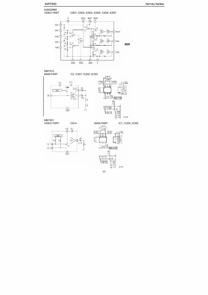
5/13/2018 AVR7300 sm - slidepdf.com
http://slidepdf.com/reader/full/avr7300-sm 77/158
MM1510
MAIN PART IC2, IC201, IC202, IC203
MM1511
MAIN PART IC206
AVR7300 harman/kardon

5/13/2018 AVR7300 sm - slidepdf.com
http://slidepdf.com/reader/full/avr7300-sm 78/158
PHOTOCOUPLER PC-17T1
VIDEO PART IC1, IC2 MAIN PART IC219, IC220
TC9163AF
PROCESSOR IC3
AVR7300 harman/kardon

5/13/2018 AVR7300 sm - slidepdf.com
http://slidepdf.com/reader/full/avr7300-sm 79/158
PROCESSOR IC3
MM1232
VIDEO PART IC604, IC608
FLI2300 PQFP (VIDEO ENHANCER IC)
FAROUDJA PART IC11
AVR7300 harman/kardon

5/13/2018 AVR7300 sm - slidepdf.com
http://slidepdf.com/reader/full/avr7300-sm 80/158
TC9273F
PROCESSOR IC6.IC10
AVR7300 harman/kardon
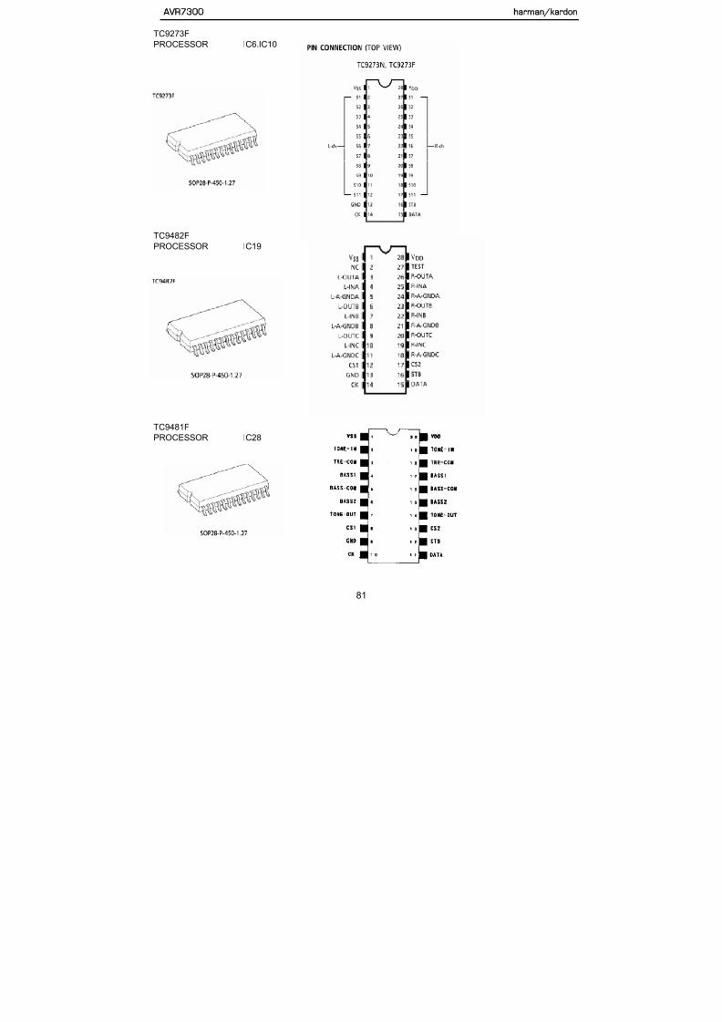
5/13/2018 AVR7300 sm - slidepdf.com
http://slidepdf.com/reader/full/avr7300-sm 81/158
TC9482F
PROCESSOR IC19
KIC9459F
PORCESSOR IC2.IC18
AVR7300 harman/kardon

5/13/2018 AVR7300 sm - slidepdf.com
http://slidepdf.com/reader/full/avr7300-sm 82/158
24PIN
TSH95VIDEO PART IC613
SOP 16PIN
K4S161622D-TC80
DSP PART IC14
AVR7300 harman/kardon
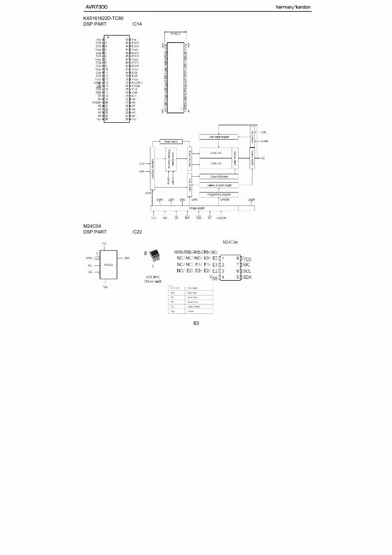
5/13/2018 AVR7300 sm - slidepdf.com
http://slidepdf.com/reader/full/avr7300-sm 83/158
74VHCT244A
DSP PART IC17, IC18, IC25
AVR7300 harman/kardon

5/13/2018 AVR7300 sm - slidepdf.com
http://slidepdf.com/reader/full/avr7300-sm 84/158
NJM2068MDSP PART IC31 ~ IC50
PROCESSORR PART IC1.IC4.IC7.IC8.IC9.IC11.IC12.IC13.IC15.IC16.IC17.IC20
IC21.IC23.IC24.IC25.IC26.IC27,IC29,IC30
LC74763M
VIDEO PART IC209
HCA-18LL03
FRONT PART DP71
AVR7300 harman/kardon

5/13/2018 AVR7300 sm - slidepdf.com
http://slidepdf.com/reader/full/avr7300-sm 85/158
KIA78R08API
DSP PART IC21
AVR7300 harman/kardon

5/13/2018 AVR7300 sm - slidepdf.com
http://slidepdf.com/reader/full/avr7300-sm 86/158
RPM6938-RSIP-A3
FRONT PART RM 71
CS5361
DSP PART IC27, IC28, IC29, IC30
AVR7300 harman/kardon

5/13/2018 AVR7300 sm - slidepdf.com
http://slidepdf.com/reader/full/avr7300-sm 87/158
CS49400
DSP PART IC11
VPC3230D IC VIDEO DECODER
FAROUDJA PART IC10
AVR7300 harman/kardon

5/13/2018 AVR7300 sm - slidepdf.com
http://slidepdf.com/reader/full/avr7300-sm 88/158
MM1623 VIDEO DRIVER
PAROUDJA PART IC14
AVR7300 harman/kardon

5/13/2018 AVR7300 sm - slidepdf.com
http://slidepdf.com/reader/full/avr7300-sm 89/158
PAROUDJA PART IC14
MM1623
K4S643232F TC60/TC70 (64M SDRAM)
AVR7300 harman/kardon

5/13/2018 AVR7300 sm - slidepdf.com
http://slidepdf.com/reader/full/avr7300-sm 90/158
K4S643232F- TC60/TC70 (64M SDRAM)
FAROUDJA PART IC12
KRA107M
DTA114YS
VIDEO PA Q201,Q201
AVR7300 harman/kardon

5/13/2018 AVR7300 sm - slidepdf.com
http://slidepdf.com/reader/full/avr7300-sm 91/158
KRC107M
DTC114YS
3CH AMP Q901
4CH AMP Q802
2SA933
FAROUDJ Q100,Q101,Q104
MAIN PARQ213 Q214
AVR7300 harman/kardon

5/13/2018 AVR7300 sm - slidepdf.com
http://slidepdf.com/reader/full/avr7300-sm 92/158
MAIN PARQ213,Q214
SUPPLY Q501
C
B
E
2SC1740S
3CHAMP Q926,Q927,Q928MAIN Q211,Q7
C
B
E
KTA1024Y
3CHAMP Q901
4CHAMP Q801 C
KTA1266
3CHAMP Q925
AVR7300 harman/kardon

5/13/2018 AVR7300 sm - slidepdf.com
http://slidepdf.com/reader/full/avr7300-sm 93/158
KTA1268
3CH AMP Q107,Q207,Q307
4CH AMP Q407,Q507,Q607,Q707
KTC3200
3CHAMP Q101,Q102,Q103,Q104,Q122,Q201~4,Q222,Q301,Q302,Q303,Q304,Q322
4CHAMP Q401~4,Q422,Q501~Q504,Q522,Q601~4,Q622,Q701~4,Q722
AVR7300 harman/kardon
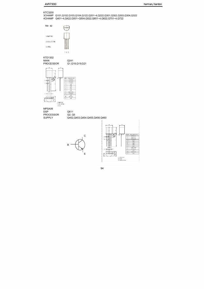
5/13/2018 AVR7300 sm - slidepdf.com
http://slidepdf.com/reader/full/avr7300-sm 94/158
KTD1302
MAIN Q241
PROCESSOR Q1,Q18,Q19,Q21
MPSA56
PROCESSOR Q4,Q6
AVR7300 harman/kardon
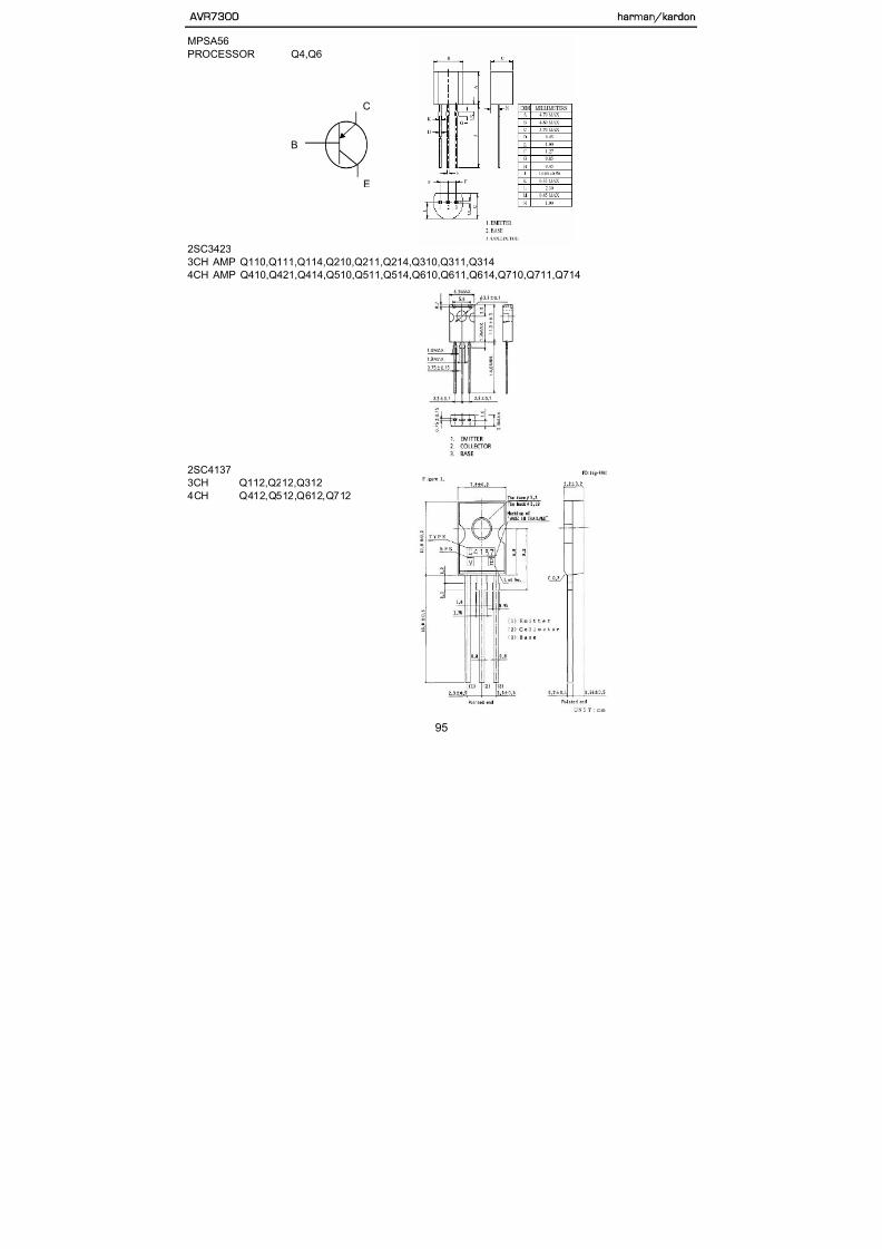
5/13/2018 AVR7300 sm - slidepdf.com
http://slidepdf.com/reader/full/avr7300-sm 95/158
C
B
E
2SC3423
3CH AMP Q110,Q111,Q114,Q210,Q211,Q214,Q310,Q311,Q314
4CH AMP Q410,Q421,Q414,Q510,Q511,Q514,Q610,Q611,Q614,Q710,Q711,Q714
2SA1360
3CH AMP Q108,Q109,Q208,Q209,Q308,Q309,Q116,Q216,Q316
4CH AMP Q408,Q409,Q508,Q509,Q608,Q609,Q708,Q709,Q416,Q516,Q616,Q716
AVR7300 harman/kardon

5/13/2018 AVR7300 sm - slidepdf.com
http://slidepdf.com/reader/full/avr7300-sm 96/158
2SC4883
3CH AMP Q117,Q217,Q317
4CH AMP Q417,Q517,Q617,Q717
2SA1943
3CH AMP Q120,Q121,Q120,Q221,Q320,Q321
4CCH AM Q420,Q421,Q520,Q521,Q620,Q621,Q720,Q721
AVR7300 harman/kardon

5/13/2018 AVR7300 sm - slidepdf.com
http://slidepdf.com/reader/full/avr7300-sm 97/158
2SC5200
3CH AMP Q118,Q119,Q218,Q219,Q318,Q319,4CH AMP Q418,Q419,Q518,Q519,Q618,Q619,Q718,Q7198
SMD
DTA114YKAP
DSP Q402,Q403
MAIN Q4,Q215,Q617,Q717
PROCESSOR Q3,Q13,Q14,Q17,Q20,Q23,Q25,Q32,Q34,Q35,Q37,Q41,Q43,Q50,Q52
AVR7300 harman/kardon

5/13/2018 AVR7300 sm - slidepdf.com
http://slidepdf.com/reader/full/avr7300-sm 98/158
VIDEO Q603,Q604
DTC114YKA
DSP Q600,Q601,Q604,Q605Q606,Q607,Q608,Q609,Q612,Q613FAROUDJ Q106,Q107
FRONT Q701,Q703,Q704,Q705
MAIN Q1,Q2,Q201,Q202,Q203,Q204,Q212
PROCESSOR Q54,Q22
VEDIO Q611,Q612,Q613
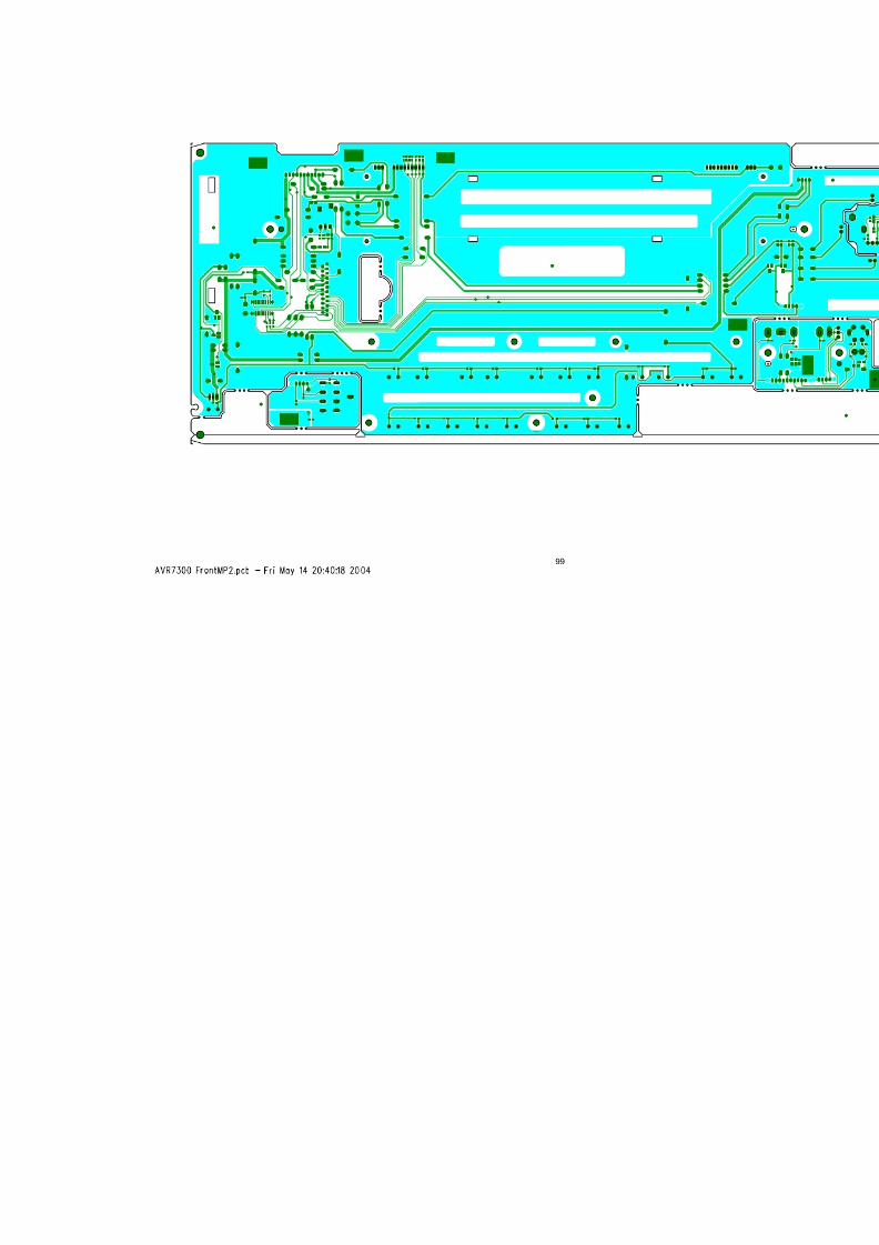
5/13/2018 AVR7300 sm - slidepdf.com
http://slidepdf.com/reader/full/avr7300-sm 99/158

5/13/2018 AVR7300 sm - slidepdf.com
http://slidepdf.com/reader/full/avr7300-sm 100/158

5/13/2018 AVR7300 sm - slidepdf.com
http://slidepdf.com/reader/full/avr7300-sm 101/158

5/13/2018 AVR7300 sm - slidepdf.com
http://slidepdf.com/reader/full/avr7300-sm 102/158

5/13/2018 AVR7300 sm - slidepdf.com
http://slidepdf.com/reader/full/avr7300-sm 103/158

5/13/2018 AVR7300 sm - slidepdf.com
http://slidepdf.com/reader/full/avr7300-sm 104/158

5/13/2018 AVR7300 sm - slidepdf.com
http://slidepdf.com/reader/full/avr7300-sm 105/158

5/13/2018 AVR7300 sm - slidepdf.com
http://slidepdf.com/reader/full/avr7300-sm 106/158

5/13/2018 AVR7300 sm - slidepdf.com
http://slidepdf.com/reader/full/avr7300-sm 107/158

5/13/2018 AVR7300 sm - slidepdf.com
http://slidepdf.com/reader/full/avr7300-sm 108/158

5/13/2018 AVR7300 sm - slidepdf.com
http://slidepdf.com/reader/full/avr7300-sm 109/158

5/13/2018 AVR7300 sm - slidepdf.com
http://slidepdf.com/reader/full/avr7300-sm 110/158

5/13/2018 AVR7300 sm - slidepdf.com
http://slidepdf.com/reader/full/avr7300-sm 111/158

5/13/2018 AVR7300 sm - slidepdf.com
http://slidepdf.com/reader/full/avr7300-sm 112/158

5/13/2018 AVR7300 sm - slidepdf.com
http://slidepdf.com/reader/full/avr7300-sm 113/158

5/13/2018 AVR7300 sm - slidepdf.com
http://slidepdf.com/reader/full/avr7300-sm 114/158

5/13/2018 AVR7300 sm - slidepdf.com
http://slidepdf.com/reader/full/avr7300-sm 115/158

5/13/2018 AVR7300 sm - slidepdf.com
http://slidepdf.com/reader/full/avr7300-sm 116/158

5/13/2018 AVR7300 sm - slidepdf.com
http://slidepdf.com/reader/full/avr7300-sm 117/158

5/13/2018 AVR7300 sm - slidepdf.com
http://slidepdf.com/reader/full/avr7300-sm 118/158

5/13/2018 AVR7300 sm - slidepdf.com
http://slidepdf.com/reader/full/avr7300-sm 119/158

5/13/2018 AVR7300 sm - slidepdf.com
http://slidepdf.com/reader/full/avr7300-sm 120/158

5/13/2018 AVR7300 sm - slidepdf.com
http://slidepdf.com/reader/full/avr7300-sm 121/158

5/13/2018 AVR7300 sm - slidepdf.com
http://slidepdf.com/reader/full/avr7300-sm 122/158
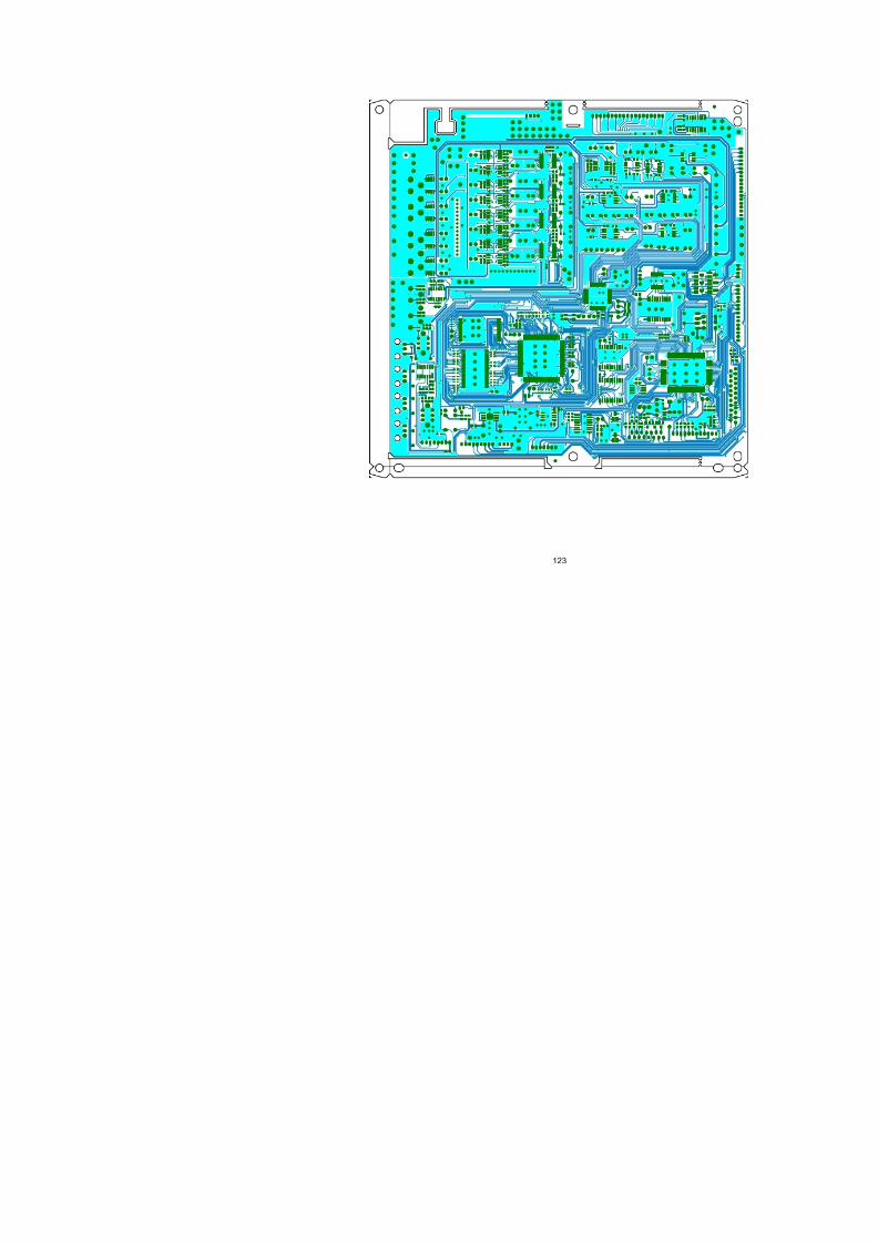
5/13/2018 AVR7300 sm - slidepdf.com
http://slidepdf.com/reader/full/avr7300-sm 123/158

5/13/2018 AVR7300 sm - slidepdf.com
http://slidepdf.com/reader/full/avr7300-sm 124/158

5/13/2018 AVR7300 sm - slidepdf.com
http://slidepdf.com/reader/full/avr7300-sm 125/158

5/13/2018 AVR7300 sm - slidepdf.com
http://slidepdf.com/reader/full/avr7300-sm 126/158
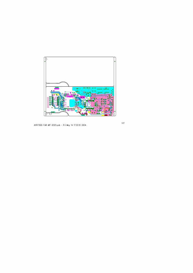
5/13/2018 AVR7300 sm - slidepdf.com
http://slidepdf.com/reader/full/avr7300-sm 127/158

5/13/2018 AVR7300 sm - slidepdf.com
http://slidepdf.com/reader/full/avr7300-sm 128/158

5/13/2018 AVR7300 sm - slidepdf.com
http://slidepdf.com/reader/full/avr7300-sm 129/158
129

5/13/2018 AVR7300 sm - slidepdf.com
http://slidepdf.com/reader/full/avr7300-sm 130/158
130
5/13/2018 AVR7300 sm - slidepdf.com
http://slidepdf.com/reader/full/avr7300-sm 131/158
131

5/13/2018 AVR7300 sm - slidepdf.com
http://slidepdf.com/reader/full/avr7300-sm 132/158
132

5/13/2018 AVR7300 sm - slidepdf.com
http://slidepdf.com/reader/full/avr7300-sm 133/158
133

5/13/2018 AVR7300 sm - slidepdf.com
http://slidepdf.com/reader/full/avr7300-sm 134/158
134

5/13/2018 AVR7300 sm - slidepdf.com
http://slidepdf.com/reader/full/avr7300-sm 135/158
135

5/13/2018 AVR7300 sm - slidepdf.com
http://slidepdf.com/reader/full/avr7300-sm 136/158
136

5/13/2018 AVR7300 sm - slidepdf.com
http://slidepdf.com/reader/full/avr7300-sm 137/158
137

5/13/2018 AVR7300 sm - slidepdf.com
http://slidepdf.com/reader/full/avr7300-sm 138/158
138

5/13/2018 AVR7300 sm - slidepdf.com
http://slidepdf.com/reader/full/avr7300-sm 139/158
139

5/13/2018 AVR7300 sm - slidepdf.com
http://slidepdf.com/reader/full/avr7300-sm 140/158
140

5/13/2018 AVR7300 sm - slidepdf.com
http://slidepdf.com/reader/full/avr7300-sm 141/158
141

5/13/2018 AVR7300 sm - slidepdf.com
http://slidepdf.com/reader/full/avr7300-sm 142/158
142

5/13/2018 AVR7300 sm - slidepdf.com
http://slidepdf.com/reader/full/avr7300-sm 143/158
143

5/13/2018 AVR7300 sm - slidepdf.com
http://slidepdf.com/reader/full/avr7300-sm 144/158
144
5/13/2018 AVR7300 sm - slidepdf.com
http://slidepdf.com/reader/full/avr7300-sm 145/158
145
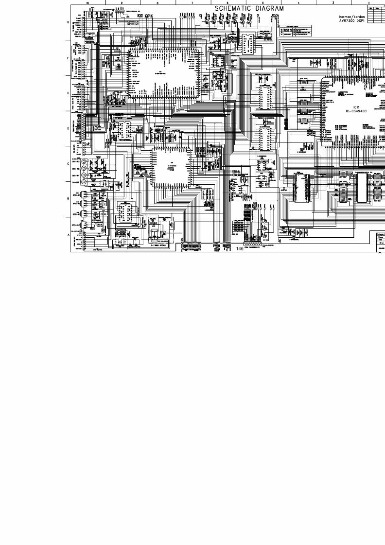
5/13/2018 AVR7300 sm - slidepdf.com
http://slidepdf.com/reader/full/avr7300-sm 146/158

5/13/2018 AVR7300 sm - slidepdf.com
http://slidepdf.com/reader/full/avr7300-sm 147/158

5/13/2018 AVR7300 sm - slidepdf.com
http://slidepdf.com/reader/full/avr7300-sm 148/158

5/13/2018 AVR7300 sm - slidepdf.com
http://slidepdf.com/reader/full/avr7300-sm 149/158

5/13/2018 AVR7300 sm - slidepdf.com
http://slidepdf.com/reader/full/avr7300-sm 150/158

5/13/2018 AVR7300 sm - slidepdf.com
http://slidepdf.com/reader/full/avr7300-sm 151/158

5/13/2018 AVR7300 sm - slidepdf.com
http://slidepdf.com/reader/full/avr7300-sm 152/158

5/13/2018 AVR7300 sm - slidepdf.com
http://slidepdf.com/reader/full/avr7300-sm 153/158
AVR7300 harman/kardon

5/13/2018 AVR7300 sm - slidepdf.com
http://slidepdf.com/reader/full/avr7300-sm 154/158

5/13/2018 AVR7300 sm - slidepdf.com
http://slidepdf.com/reader/full/avr7300-sm 155/158
AVR7300
harman/kardon

5/13/2018 AVR7300 sm - slidepdf.com
http://slidepdf.com/reader/full/avr7300-sm 156/158

5/13/2018 AVR7300 sm - slidepdf.com
http://slidepdf.com/reader/full/avr7300-sm 157/158
REF
#PART NUMBER DESCRIPTION QTY
1-1 ZQD0501HA00-9 CUSHION POLY EPS RIGHT AVR7300 1
1-2 ZQD0502HA00-5 CUSHION POLY EPS LEFT AVR7300 1
ZKD0504HA00-7 BOX CARTON AVR7300 (120v)2
ZKD1004HA00 BOX CARTON AVR7300 (230v)
1
3 ZHD0501AAWH-2 FILM SHEET PE 1050X1050XT0.5 1
4 H01-ATALF039ABK-A ANTENNA WIRE AM LOOP CT01-AM 0 0 1
H01-WAB01200203-9 ANTENNA WIRE 75 CT02-FM 0 0 (120v)5
H01-WAD01200303 ANTENNA WIRE 75 CT02-FM 0 0 (230v)
1
6 H01-RYC1202HA00-5 REMOCON ZONE 2 1
H01-RYD0501HA00-0 REMOCON AVR7300 (120v)7
H01-RYD1001HA00 REMOCON AVR7300 (230v)
1
8 ZBP00173851-2 BAG PE 170X380MMX0.17 1
9 ZKC1156HA00-A CARD POST 1
10 ZKC1113HA00-9 CARD WARRANTY 1
AVR7300 harman/kardon

5/13/2018 AVR7300 sm - slidepdf.com
http://slidepdf.com/reader/full/avr7300-sm 158/158
11 ZKC1214HA00-A LABEL SAFETY LEAFLET 1
ZKD0501HA00-8 OWNER’S MANUAL AVR7300 (120v)12
ZKD1001HA00 OWNER’S MANUAL AVR7300 (230v)
1
13 BATTERY ALKALINE 1.5V AAA 6
14 ZKD0573HA00-9 LABEL BARCODE AVR7300 US 2
15 H01-WAUSA2103BK-1 POWER CORD WS SJT#14*2C L=2M
16 ZKD05H03A00-A PAD ENDCAP PAD UPPER 1
17 ZKD05H04A00-7 PAD ENDCAP PAD INNER 2
18 ZKGEN56HA00-5 ENVELOPE POLISHING CLOTH 1
19 ZKC11H96A00-1 POLISHING CLOTH 1
20 ZQD0503HA00-1 CUSHION BOTTOM AVR7300 1
158