aveva piping design
TRANSCRIPT

VANTAGE Plant Design (PDMS) Version 11.6
Module 5 Piping Design Training Manual
VANTAGE TRAINING VANTAGE TRAINING VANTAGE TRAINING VANTAGE TRAINING
Revision Log
Date Page(s) Revision Description of Revision Release
Updates Updates to this manual will be issued as replacement pages and a new Update History Sheet complete with instructions on which pages to remove and destroy, and where to insert the new sheets. Please ensure that you have received all the updates shown on the History Sheet. All updates are highlighted by a revision code marker, which appears to the left of new material. Suggestion/Problems If you have a suggestion about this manual or the system to which it refers please report it to the training department at Fax +44 (0)1223 556669 Email [email protected] This manual provides documentation relating to products to which you may not have access or which may not be licensed to you. For further information on which products are licensed to you please refer to your licence conditions. Copyright © 2005 AVEVA Solutions All rights reserved. No part of this publication may be reproduced, stored in a retrieval system or transmitted, in any form or by any means, electronic, mechanical, photocopying, recording or otherwise, without prior written permission of AVEVA The software programs described in this document are confidential information and proprietary products of AVEVA Ltd or its licensors. Visit our website at http://www.aveva.com Printed by AVEVA Solutions on 02 October 2006
PLEASE NOTE: AVEVA has a policy of continuing product development: therefore, the information contained in this document may be subject to change without notice. AVEVA MAKES NO WARRANTY OF ANY KIND WITH REGARD TO THIS DOCUMENT, INCLUDING BUT NOT LIMITED TO, THE IMPLIED WARRANTIES OF MERCHANTABILITY AND FITNESS FOR A PARTICULAR PURPOSE. While every effort has been made to verify the accuracy of this document, AVEVA shall not be liable for errors contained herein or direct, indirect, special, incidental or consequential damages in connection with the furnishing, performance or use of this material.
3
Contents
1 Introduction.............................................................................................................................................. 4 1.1 Aim .................................................................................................................................................... 4 1.2 Objectives......................................................................................................................................... 4 1.3 Prerequisites .................................................................................................................................... 4 1.4 Course Structure ............................................................................................................................. 4 1.5 Using this guide............................................................................................................................... 4
2 Pipework Modelling................................................................................................................................. 5 2.1 Piping in PDMS: Basic Concepts................................................................................................... 5 2.2 Piping Specifications ...................................................................................................................... 5 2.3 Setting the Appropriate Specification ........................................................................................... 6 2.4 Pipework Toolbar............................................................................................................................. 6 2.5 Pipe Creation Form.......................................................................................................................... 7 2.6 Pipe Branches.................................................................................................................................. 7 2.7 Pipe Branch Heads and Tails ......................................................................................................... 7
2.7.1 Attributes for heads of branches................................................................................................ 8 2.7.2 Attributes for tails of branches ................................................................................................... 8
2.8 Pipe Branch Head / Tail Positioned Explicitly .............................................................................. 9 2.9 Pipe Branch Head / Tail Connected ............................................................................................... 9 2.10 Pipe Branch Components (Pipe Fittings).................................................................................... 10 2.11 Creating Branch Components (Pipe Fittings)............................................................................. 10 2.12 Component Creation Form ........................................................................................................... 11 2.13 Component Selection Form.......................................................................................................... 11 2.14 Branch Components List Order ................................................................................................... 12 2.15 Typical Design Explorer................................................................................................................ 12 2.16 Typical Design Explorer showing Tube ...................................................................................... 12 2.17 Arrive and Leave Points................................................................................................................ 13 2.18 The Piping Application - A Worked Example.............................................................................. 15
2.18.1 BRANCH /100-B-8/B1 showing input sequence...................................................................... 15 Exercise 1 - Creating a Second Branch ...................................................................................................... 25 Exercise 2 (Building the Pipework) ............................................................................................................. 25 Exercise 3 (Completing the Pipework)........................................................................................................ 29 Exercise 4 (Replacing Components)........................................................................................................... 29
2.19 Orientation and Positioning Components in Falling Pipelines................................................. 30 2.20 Exercise 5 (Creating a Sloping Pipe) ........................................................................................... 31
Exercise 6 (Controlling the Pipe Slope) ...................................................................................................... 32 2.21 Alternative Positioning Forms ..................................................................................................... 34
2.21.1 Position>Component>Plane Through...................................................................................... 34 2.21.2 Positioning Piping Items Relative to Other Design Items ........................................................ 34
Exercise 7 - Pipe Editing............................................................................................................................... 37 2.22 Copying Branches......................................................................................................................... 38
3 Data Consistency Checker ................................................................................................................... 39 3.1 Possible Types of Data Error ....................................................................................................... 39
3.1.1 Angular Alignment.................................................................................................................... 39 3.1.2 Axial Alignment ........................................................................................................................ 39 3.1.3 Consistent Bores...................................................................................................................... 39 3.1.4 Connection Types .................................................................................................................... 39 3.1.5 Minimum Tube Length ............................................................................................................. 39
3.2 Starting the Data Consistency Checks........................................................................................ 40 3.3 Data Consistency Check Report Format..................................................................................... 40
3.3.1 Data Consistency Diagnostic Messages ................................................................................. 41 3.4 Some Examples of Data Consistency Diagnostic Messages ................................................... 41
3.4.1 Branch Head Errors ................................................................................................................. 41 3.4.2 Branch Tail Errors .................................................................................................................... 42 3.4.3 Plain Branch Errors.................................................................................................................. 42 3.4.4 Component–Specific Diagnostics ............................................................................................ 43 3.4.5 End–Component Diagnostics .................................................................................................. 44
Exercise 8 (Data consistency check) .......................................................................................................... 44

4
Chapter 1
1 Introduction Pipe routing is probably the activity that consumes most time on any large project and it is also one, which causes the most problems. Pipe routing in PDMS has always been one of the major strengths of the system, as you will discover in this module.
1.1 Aim The following Training Manual describes the use of the Vantage Plant Design (PDMS) for Piping Design.
1.2 Objectives At the end of this training, you will be able to:
• Explain the basic concepts of pipes and branches. • Describe the use of piping specifications in PDMS. • Have a sound knowledge of branch heads and tails and the importance of component list order and flow
direction within a branch. • Understand how to create, position and orientate piping components. • Describe all the functionality of the Create Components form. • Understand the catalogue point configurations for standard components. • Orient and position components in falling lines. • Understand more complex positioning with relation to other design items.
1.3 Prerequisites The participants must have completed the M3 Basics and Functions and optionally M4 Equipment Design.
1.4 Course Structure Training will consist of oral and visual presentations, demonstrations and set exercises. Each workstation will have a training project, populated with model objects. This will be used by the trainees to practice their methods, and complete the set exercises.
1.5 Using this guide Certain text styles are used to indicate special situations throughout this document, here is a summary; Menu pull downs and button press actions. Are indicated by bold dark blue text. Information the user has to Key-in 'Will be red and in inverted commas.' Annotation for trainees benefit
Additional information
Pay close attention to
Refer to other documentation System prompts should be bold and italic in inverted commas i.e. 'Choose function' Example files or inputs will be in the courier new font, colours and styles used as before.

5
Chapter 2
2 Pipework Modelling
2.1 Piping in PDMS: Basic Concepts
The piping design hierarchy is shown above; each pipe element may own a number of branches. In turn, branches may own a number of piping components like valves and reducers. The difference between pipes and branches is that a branch is only considered to have two ends, while a pipe may have any number of ends, depending on the number of branches it owns. Below shows a pipe with three ends and two branches, where the second branch is connected to the first at the tee.
Branch 1
Branch 2
Tee
This brings in another rule that says that although a branch only has two ends, it may own components (in this case a tee), which connect to other branches. These simple concepts enable any number of piping configurations to be developed, and form the basis of all the PDMS Pipework you will encounter.
2.2 Piping Specifications In the same way that design offices have standard piping specifications, PDMS has a set of specifications from which you can choose. In fact all the components you will use in PDMS must be defined in the Catalogue and be placed in a Specification before you can use them. In the Training Project there are three such specifications:
A1A-TRA = ANSI CLASS 150 CARBON STEEL A3B-TRA = ANSI CLASS 300 CARBON STEEL F1C-TRA = ANSI CLASS 150 STAINLESS STEEL
These specifications contain all the fittings you will require for the course exercises.
6
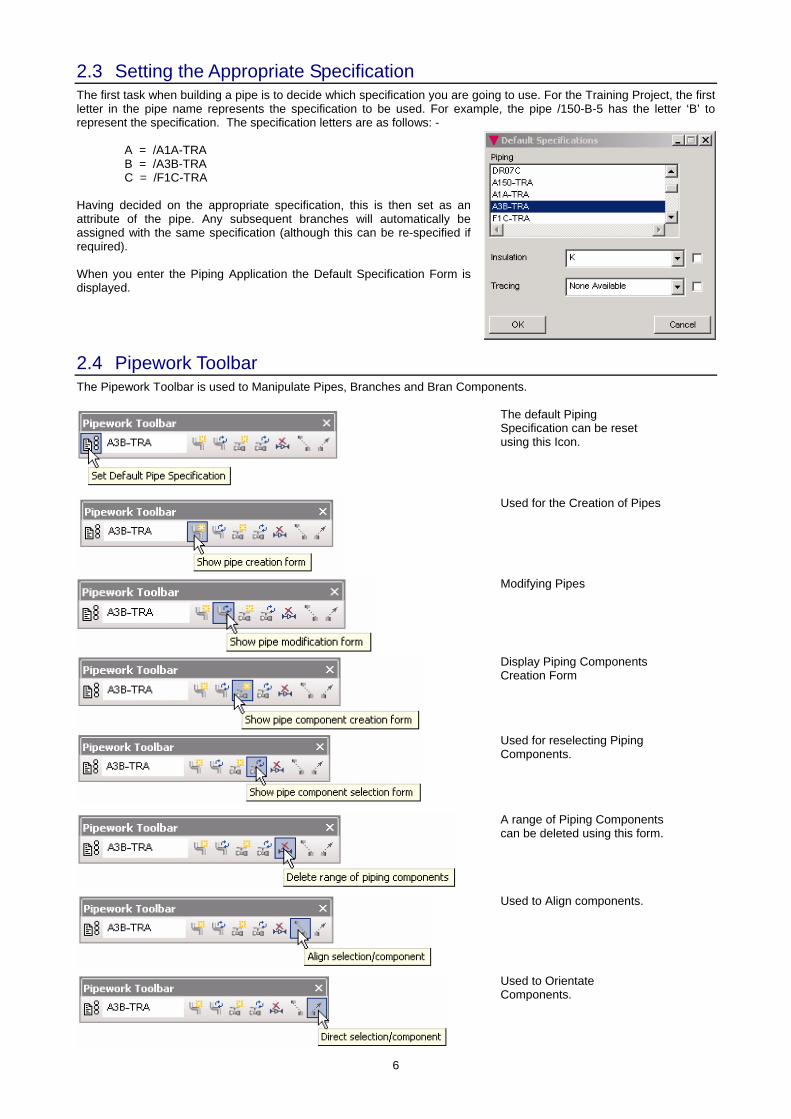
2.3 Setting the Appropriate Specification The first task when building a pipe is to decide which specification you are going to use. For the Training Project, the first letter in the pipe name represents the specification to be used. For example, the pipe /150-B-5 has the letter ‘B’ to represent the specification. The specification letters are as follows: - A = /A1A-TRA B = /A3B-TRA C = /F1C-TRA Having decided on the appropriate specification, this is then set as an attribute of the pipe. Any subsequent branches will automatically be assigned with the same specification (although this can be re-specified if required). When you enter the Piping Application the Default Specification Form is displayed.
2.4 Pipework Toolbar The Pipework Toolbar is used to Manipulate Pipes, Branches and Bran Components.
The default Piping Specification can be reset using this Icon.
Used for the Creation of Pipes
Modifying Pipes
Display Piping Components Creation Form
Used for reselecting Piping Components.
A range of Piping Components can be deleted using this form.
Used to Align components.
Used to Orientate Components.
7
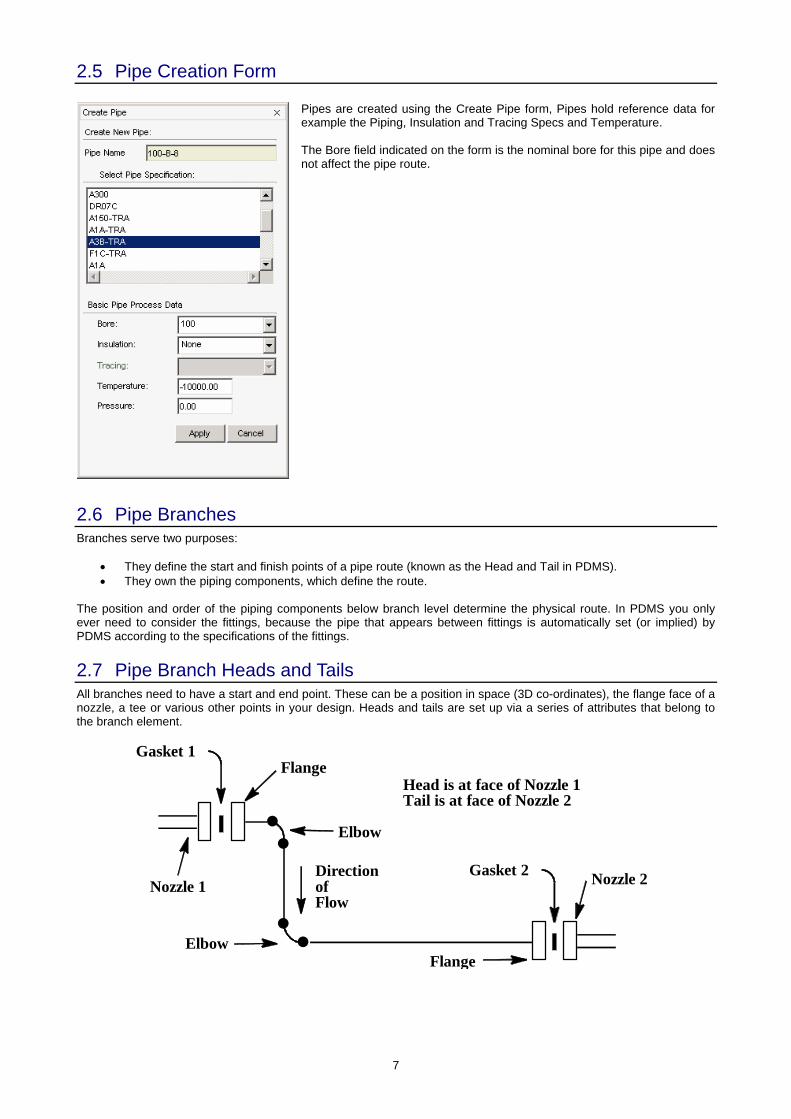
2.5 Pipe Creation Form
Pipes are created using the Create Pipe form, Pipes hold reference data for example the Piping, Insulation and Tracing Specs and Temperature. The Bore field indicated on the form is the nominal bore for this pipe and does not affect the pipe route.
2.6 Pipe Branches Branches serve two purposes:
• They define the start and finish points of a pipe route (known as the Head and Tail in PDMS). • They own the piping components, which define the route.
The position and order of the piping components below branch level determine the physical route. In PDMS you only ever need to consider the fittings, because the pipe that appears between fittings is automatically set (or implied) by PDMS according to the specifications of the fittings.
2.7 Pipe Branch Heads and Tails All branches need to have a start and end point. These can be a position in space (3D co-ordinates), the flange face of a nozzle, a tee or various other points in your design. Heads and tails are set up via a series of attributes that belong to the branch element.
Nozzle 1
Gasket 1Flange
Elbow
DirectionofFlow
Elbow
Nozzle 2
Flange
Gasket 2
Head is at face of Nozzle 1Tail is at face of Nozzle 2
8
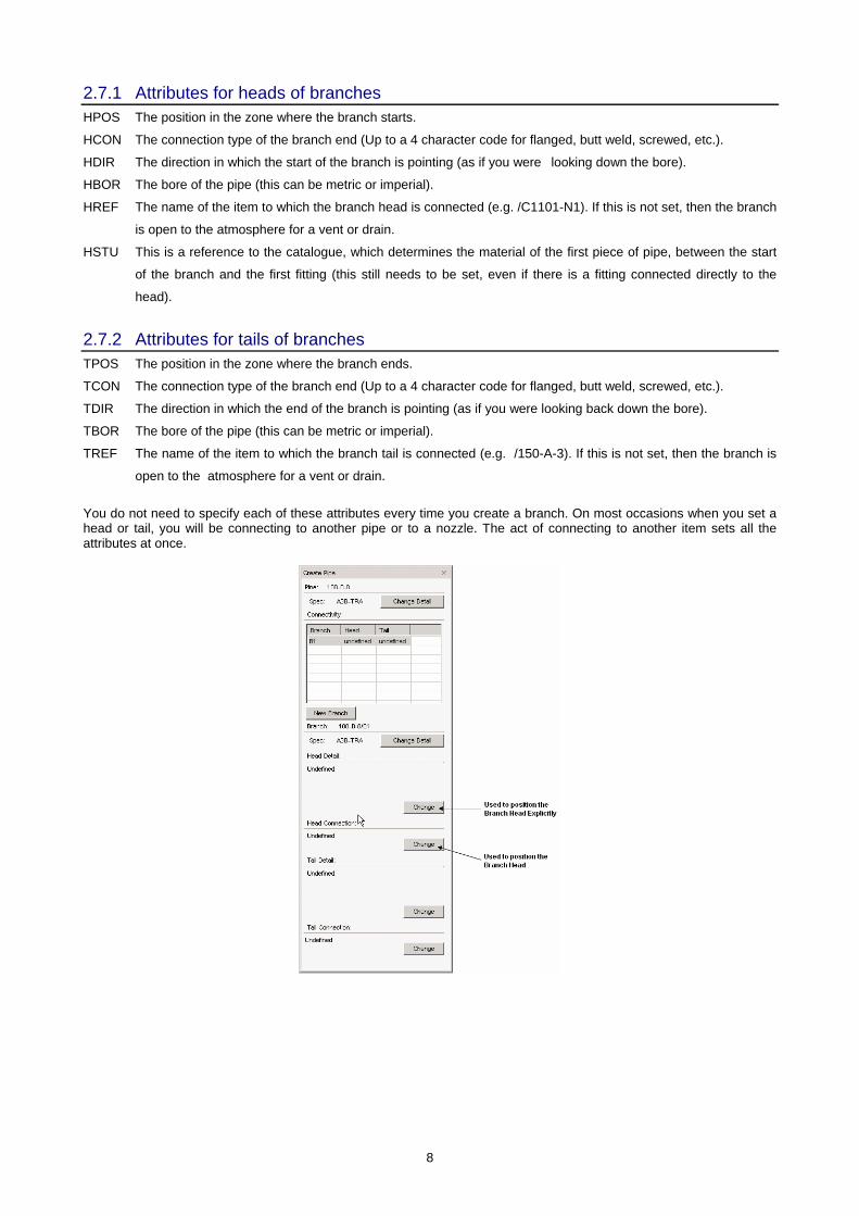
2.7.1 Attributes for heads of branches HPOS The position in the zone where the branch starts.
HCON The connection type of the branch end (Up to a 4 character code for flanged, butt weld, screwed, etc.).
HDIR The direction in which the start of the branch is pointing (as if you were looking down the bore).
HBOR The bore of the pipe (this can be metric or imperial).
HREF The name of the item to which the branch head is connected (e.g. /C1101-N1). If this is not set, then the branch
is open to the atmosphere for a vent or drain.
HSTU This is a reference to the catalogue, which determines the material of the first piece of pipe, between the start
of the branch and the first fitting (this still needs to be set, even if there is a fitting connected directly to the
head).
2.7.2 Attributes for tails of branches TPOS The position in the zone where the branch ends.
TCON The connection type of the branch end (Up to a 4 character code for flanged, butt weld, screwed, etc.).
TDIR The direction in which the end of the branch is pointing (as if you were looking back down the bore).
TBOR The bore of the pipe (this can be metric or imperial).
TREF The name of the item to which the branch tail is connected (e.g. /150-A-3). If this is not set, then the branch is
open to the atmosphere for a vent or drain.
You do not need to specify each of these attributes every time you create a branch. On most occasions when you set a head or tail, you will be connecting to another pipe or to a nozzle. The act of connecting to another item sets all the attributes at once.
9
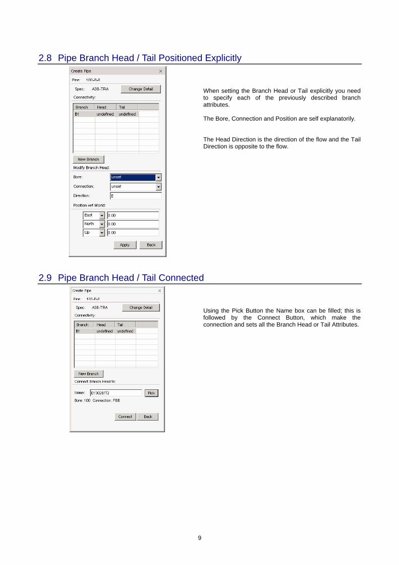
2.8 Pipe Branch Head / Tail Positioned Explicitly
When setting the Branch Head or Tail explicitly you need to specify each of the previously described branch attributes. The Bore, Connection and Position are self explanatorily. The Head Direction is the direction of the flow and the Tail Direction is opposite to the flow.
2.9 Pipe Branch Head / Tail Connected
Using the Pick Button the Name box can be filled; this is followed by the Connect Button, which make the connection and sets all the Branch Head or Tail Attributes.
10
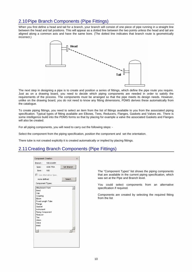
2.10 Pipe Branch Components (Pipe Fittings) When you first define a head and tail for a branch, your branch will consist of one piece of pipe running in a straight line between the head and tail positions. This will appear as a dotted line between the two points unless the head and tail are aligned along a common axis and have the same bore. (The dotted line indicates that branch route is geometrically incorrect.)
The next step in designing a pipe is to create and position a series of fittings, which define the pipe route you require. Just as on a drawing board, you need to decide which piping components are needed in order to satisfy the requirements of the process. The components must be arranged so that the pipe meets its design needs. However, unlike on the drawing board, you do not need to know any fitting dimensions, PDMS derives these automatically from the catalogue. To create piping fittings, you need to select an item from the list of fittings available to you from the associated piping specification. Typical types of fitting available are Elbows, Tees, Reducers, Flanges, Gaskets and Valves etc. There is some intelligence build into the PDMS forms so that by placing for example a valve the associated Gaskets and Flanges will also be created. For all piping components, you will need to carry out the following steps: - Select the component from the piping specification, position the component and set the orientation. There tube is not created explicitly it is created automatically or implied by placing fittings.
2.11 Creating Branch Components (Pipe Fittings)
The “Component Types” list shows the piping components that are available in the current piping specification, which was set at the Pipe and Branch level. You could select components from an alternative specification if required. Components are created by selecting the required fitting from the list
11
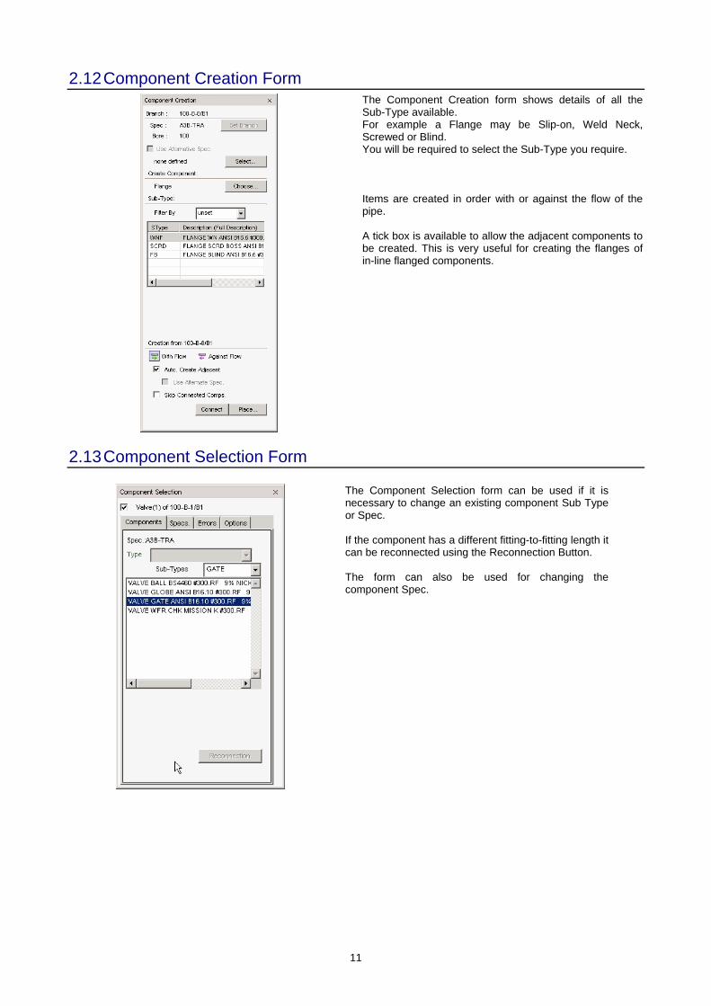
2.12 Component Creation Form
The Component Creation form shows details of all the Sub-Type available. For example a Flange may be Slip-on, Weld Neck, Screwed or Blind. You will be required to select the Sub-Type you require. Items are created in order with or against the flow of the pipe. A tick box is available to allow the adjacent components to be created. This is very useful for creating the flanges of in-line flanged components.
2.13 Component Selection Form
The Component Selection form can be used if it is necessary to change an existing component Sub Type or Spec. If the component has a different fitting-to-fitting length it can be reconnected using the Reconnection Button. The form can also be used for changing the component Spec.
12
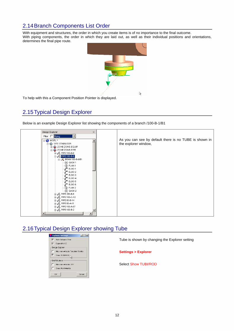
2.14 Branch Components List Order With equipment and structures, the order in which you create items is of no importance to the final outcome. With piping components, the order in which they are laid out, as well as their individual positions and orientations, determines the final pipe route.
To help with this a Component Position Pointer is displayed.
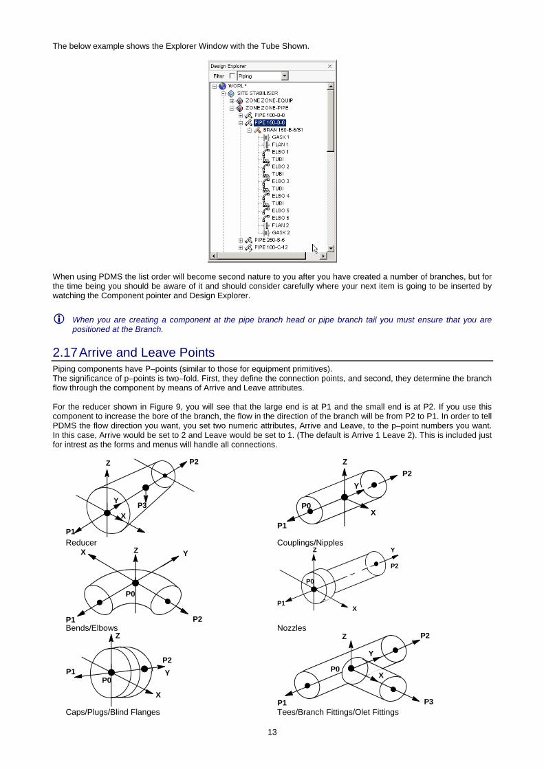
2.15 Typical Design Explorer Below is an example Design Explorer list showing the components of a branch /100-B-1/B1
As you can see by default there is no TUBE is shown in the explorer window,
2.16 Typical Design Explorer showing Tube
Tube is shown by changing the Explorer setting Settings > Explorer Select Show TUBI/ROD
13
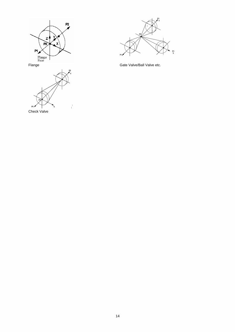
The below example shows the Explorer Window with the Tube Shown.
When using PDMS the list order will become second nature to you after you have created a number of branches, but for the time being you should be aware of it and should consider carefully where your next item is going to be inserted by watching the Component pointer and Design Explorer.
When you are creating a component at the pipe branch head or pipe branch tail you must ensure that you are positioned at the Branch.
2.17 Arrive and Leave Points Piping components have P–points (similar to those for equipment primitives). The significance of p–points is two–fold. First, they define the connection points, and second, they determine the branch flow through the component by means of Arrive and Leave attributes. For the reducer shown in Figure 9, you will see that the large end is at P1 and the small end is at P2. If you use this component to increase the bore of the branch, the flow in the direction of the branch will be from P2 to P1. In order to tell PDMS the flow direction you want, you set two numeric attributes, Arrive and Leave, to the p–point numbers you want. In this case, Arrive would be set to 2 and Leave would be set to 1. (The default is Arrive 1 Leave 2). This is included just for intrest as the forms and menus will handle all connections.
P1
Z P2
P3 Y
X
P1
P2
P0X
Y
Z
Reducer Couplings/Nipples
P1
P0
P2
X YZ
P2
Z Y
X
P0
P1
Bends/Elbows Nozzles
P2Y
X
P0P1
Z
P1
P2
P0X
Y
Z
P3 Caps/Plugs/Blind Flanges Tees/Branch Fittings/Olet Fittings
14
P0
P1
P2Y
P3 X
Flange Gate Valve/Ball Valve etc.
Check Valve
15
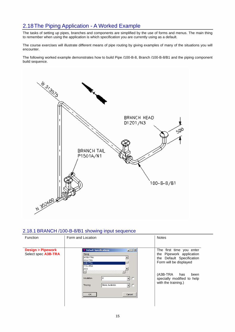
2.18 The Piping Application - A Worked Example The tasks of setting up pipes, branches and components are simplified by the use of forms and menus. The main thing to remember when using the application is which specification you are currently using as a default. The course exercises will illustrate different means of pipe routing by giving examples of many of the situations you will encounter. The following worked example demonstrates how to build Pipe /100-B-8, Branch /100-B-8/B1 and the piping component build sequence.
2.18.1 BRANCH /100-B-8/B1 showing input sequence Function Form and Location Notes
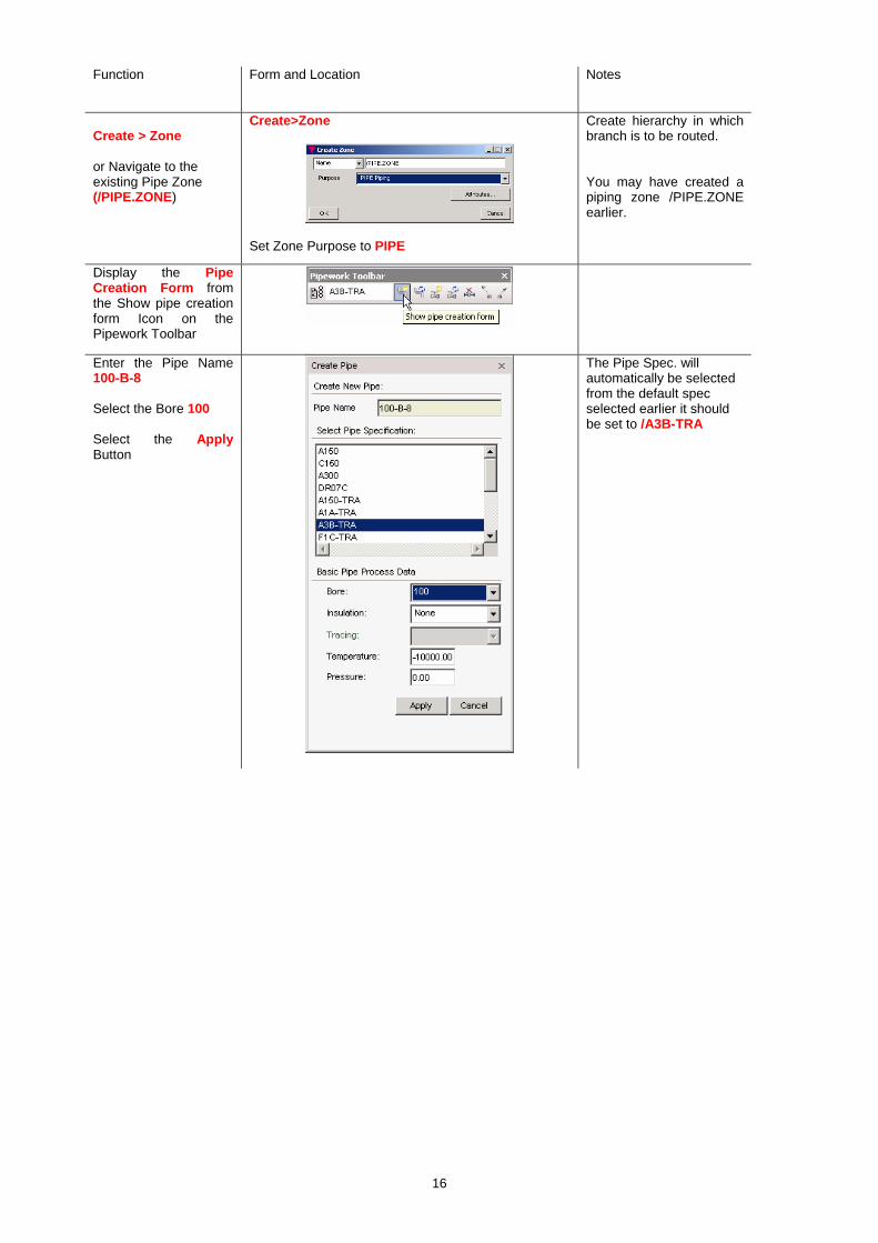
Design > Pipework Select spec A3B-TRA
The first time you enter the Pipework application the Default Specification Form will be displayed (A3B-TRA has been specially modified to help with the training.)
16
Function Form and Location Notes
Create > Zone or Navigate to the existing Pipe Zone (/PIPE.ZONE)
Create>Zone
Set Zone Purpose to PIPE
Create hierarchy in which branch is to be routed. You may have created a piping zone /PIPE.ZONE earlier.
Display the Pipe Creation Form from the Show pipe creation form Icon on the Pipework Toolbar
Enter the Pipe Name 100-B-8 Select the Bore 100 Select the Apply Button
The Pipe Spec. will automatically be selected from the default spec selected earlier it should be set to /A3B-TRA
17
Function Form and Location Notes
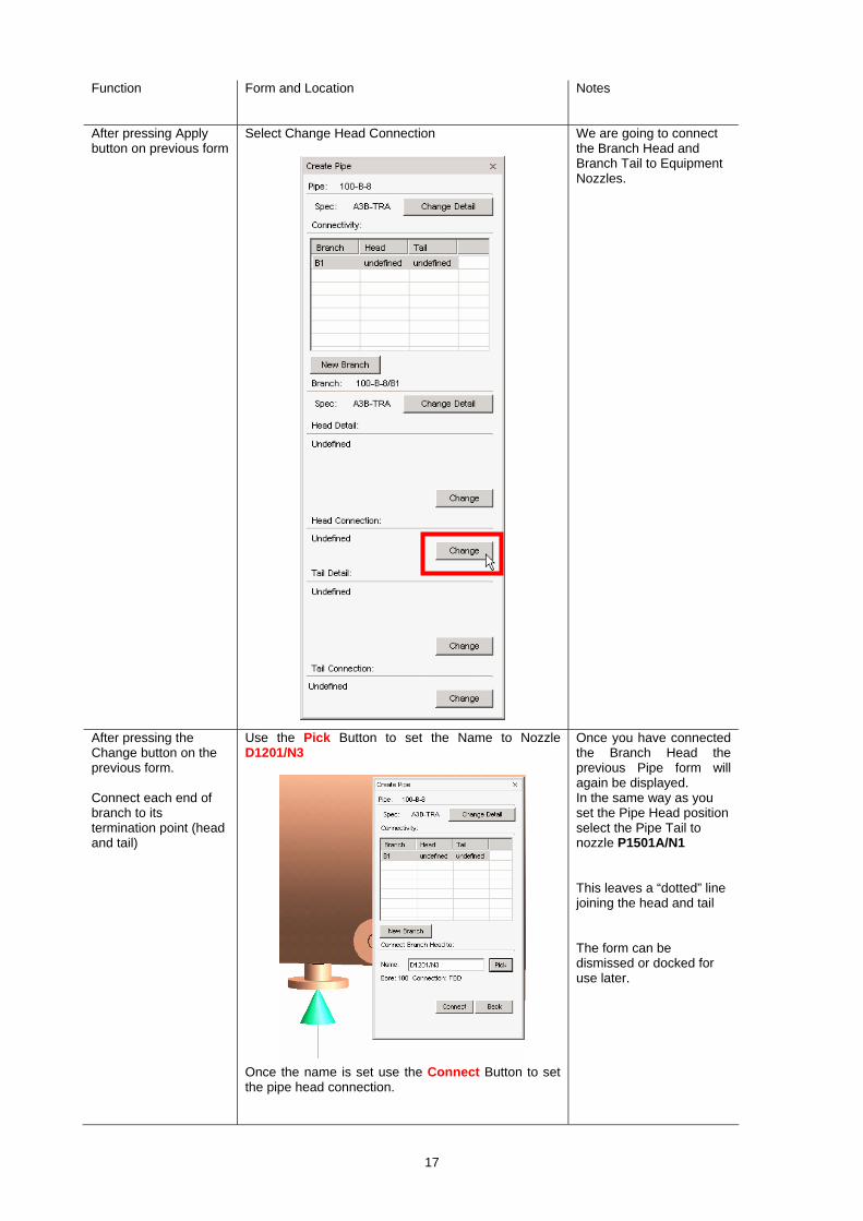
After pressing Apply button on previous form
Select Change Head Connection
We are going to connect the Branch Head and Branch Tail to Equipment Nozzles.
After pressing the Change button on the previous form. Connect each end of branch to its termination point (head and tail)
Use the Pick Button to set the Name to Nozzle D1201/N3
Once the name is set use the Connect Button to set the pipe head connection.
Once you have connected the Branch Head the previous Pipe form will again be displayed. In the same way as you set the Pipe Head position select the Pipe Tail to nozzle P1501A/N1 This leaves a “dotted” line joining the head and tail The form can be dismissed or docked for use later.

18
Function Form and Location Notes
Display the Pipe Component Creation Form from the Show pipe creation form Icon on the Pipework Toolbar
Note where possible we will create the main pipe route and add valves and other in-line fittings later.
We are going to connect a Flange and associated Gasket to the Branch Head, which is in turn connected to a Nozzle.
Select Flange
PDMS will select an appropriate Gasket so we will select a Flange from the Component Types.
In the Design Explorer you will be set at the Bran.
Select the Weld Neck Flange (WNF), ensure the component creation is With Flow and the Auto. Create Adjacent button is Ticked.
Using the same form we will select a Weld Neck Flange for the Pipe Tail. In the Design Explorer navigate back up to Branch Level. Change the creation form to Against Flow Select Connect You should now have a Gasket and Flange at the Branch Head and the Branch Tail.
19
Function Form and Location Notes
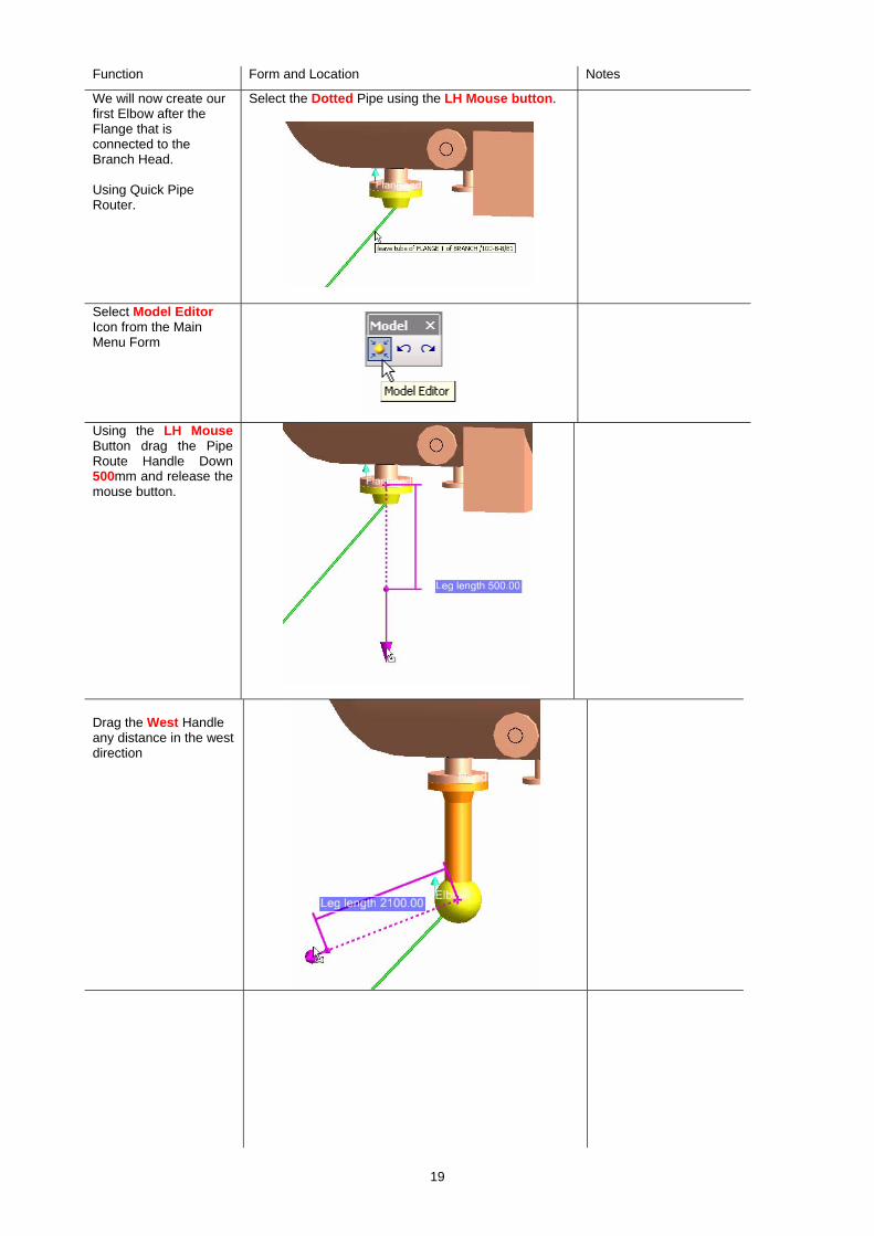
We will now create our first Elbow after the Flange that is connected to the Branch Head. Using Quick Pipe Router.
Select the Dotted Pipe using the LH Mouse button.
Select Model Editor Icon from the Main Menu Form
Using the LH Mouse Button drag the Pipe Route Handle Down 500mm and release the mouse button.
Drag the West Handle any distance in the west direction

20
Function Form and Location Notes
The Blob (or Sphere) on the branch will be deleted automatically later in the tutorial so it can be left for now.
Note: - The Blob will appear in the member list as an Elbow
The RH Mouse Button Options shown here are only to illustrate that they are available.
The Change in direction created will be created as an elbow this could be changed to a Bend (if there are bends available in the spec) using the Component Choice pull down that can be displayed when in Model Editor Mode. Other options are also available from this pull down and some will be used later.
Exit Model Editor Mode by deselecting the Model Editor Icon
We are now going to create an Elbow at the flange connected to the Pipe Tail Navigate to the flange on the Branch Tail using the LH Mouse Button.
Note the Component Pointer moves to the Flange to indicate where the next component will be created. The Display shows the component creation is against flow from the last time we used the Component Creation form.

21
Function Form and Location Notes The component Creation Form will still be displaying Flanges. Select the Choose Button and reselect Elbow
Elbow Selection Form
Select Connect
Select a 90Deg. Elbow (EA) Make sure the creation is Against Flow.
We will now position the elbow through a North Position of N 302600 by dragging the Elbow using Model Editor Mode. Rotate the elbow through 180 Deg.
Note: - The World Co-ordinates are displayed at the bottom of the main graphics window. Fine adjustment can be obtained using the up and down arrows on the keyboard.
Model Editor increment are adjusted as shown
Selection > Set Increments
The default setting is 50mm and 5mm for fine adjustment.
22
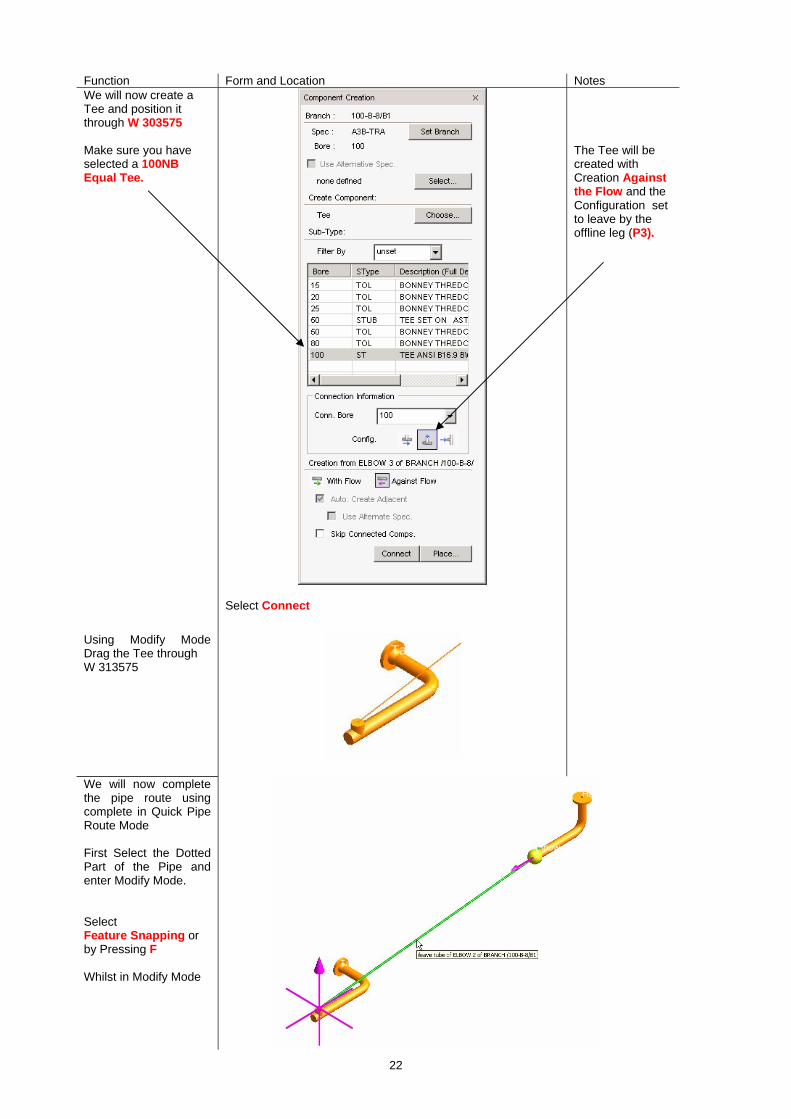
Function Form and Location Notes We will now create a Tee and position it through W 303575 Make sure you have selected a 100NB Equal Tee.
Select Connect
The Tee will be created with Creation Against the Flow and the Configuration set to leave by the offline leg (P3).
Using Modify Mode Drag the Tee through W 313575
We will now complete the pipe route using complete in Quick Pipe Route Mode First Select the Dotted Part of the Pipe and enter Modify Mode. Select Feature Snapping or by Pressing F Whilst in Modify Mode

23
Function Form and Location Notes Drag one Arrow over the other Arrow using the Right Hand Mouse Button Release the Mouse Button and select Complete
We will now place 2 Gate valves in the branch Select a Gate Valve on the Components Creation Form Use Place and identify Branch Leg for Valve
We will move the valves to the correct position later in the exercise.
As there is a choice of Flanges the Flange Component Creation form is displayed. Select Weld Neck Flange (WNF) and Done
Choose another GATE valve in a similar way.

24
Function Form and Location Notes
We will now move the Valve and its connected components Fitting to Fitting with the second Elbow in Modify Mode.
Make sure you are NOT in Feature Snap Mode using the F button whilst in Modify Mode.
It is possible to move the valve assembly to other legs in the branch, these are indicated in blue.
You can connect the Flange to the elbow.
You can also rotate the Valve in its axes.
25
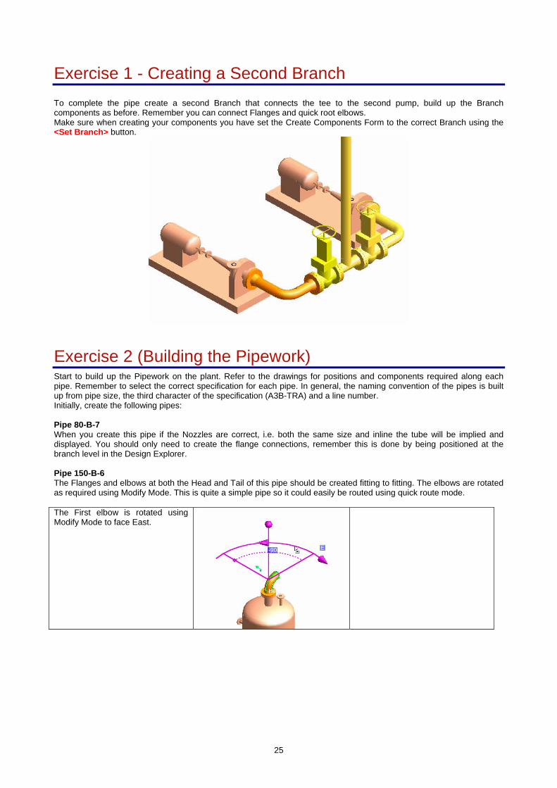
Exercise 1 - Creating a Second Branch To complete the pipe create a second Branch that connects the tee to the second pump, build up the Branch components as before. Remember you can connect Flanges and quick root elbows. Make sure when creating your components you have set the Create Components Form to the correct Branch using the <Set Branch> button.
Exercise 2 (Building the Pipework) Start to build up the Pipework on the plant. Refer to the drawings for positions and components required along each pipe. Remember to select the correct specification for each pipe. In general, the naming convention of the pipes is built up from pipe size, the third character of the specification (A3B-TRA) and a line number. Initially, create the following pipes: Pipe 80-B-7 When you create this pipe if the Nozzles are correct, i.e. both the same size and inline the tube will be implied and displayed. You should only need to create the flange connections, remember this is done by being positioned at the branch level in the Design Explorer. Pipe 150-B-6 The Flanges and elbows at both the Head and Tail of this pipe should be created fitting to fitting. The elbows are rotated as required using Modify Mode. This is quite a simple pipe so it could easily be routed using quick route mode. The First elbow is rotated using Modify Mode to face East.
26
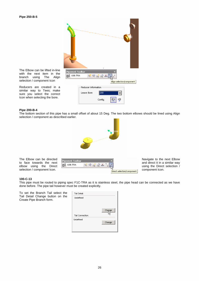
Pipe 250-B-5
The Elbow can be lifted in-line with the next item in the branch using The Align selection / component Icon
Reducers are created in a similar way to Tees; make sure you select the correct Icon when selecting the bore.
Pipe 200-B-4 The bottom section of this pipe has a small offset of about 15 Deg. The two bottom elbows should be lined using Align selection / component as described earlier.
The Elbow can be directed to face towards the next elbow using the Direct selection / component Icon.
Navigate to the next Elbow and direct it in a similar way using the Direct selection / component Icon.
100-C-13 This pipe must be routed to piping spec F1C-TRA as it is stainless steel, the pipe head can be connected as we have done before. The pipe tail however must be created explicitly. To set the Branch Tail select the Tail Detail Change button on the Create Pipe Branch form.
27
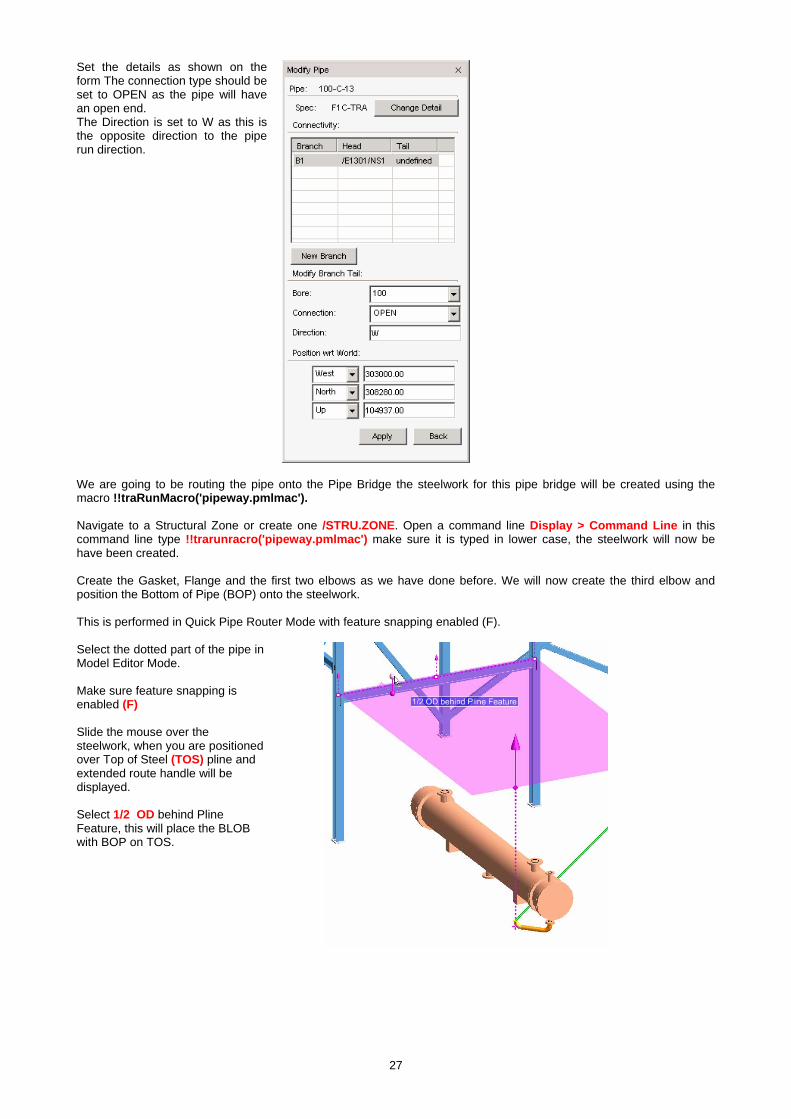
Set the details as shown on the form The connection type should be set to OPEN as the pipe will have an open end. The Direction is set to W as this is the opposite direction to the pipe run direction.
We are going to be routing the pipe onto the Pipe Bridge the steelwork for this pipe bridge will be created using the macro !!traRunMacro('pipeway.pmlmac'). Navigate to a Structural Zone or create one /STRU.ZONE. Open a command line Display > Command Line in this command line type !!trarunracro('pipeway.pmlmac') make sure it is typed in lower case, the steelwork will now be have been created. Create the Gasket, Flange and the first two elbows as we have done before. We will now create the third elbow and position the Bottom of Pipe (BOP) onto the steelwork. This is performed in Quick Pipe Router Mode with feature snapping enabled (F). Select the dotted part of the pipe in Model Editor Mode. Make sure feature snapping is enabled (F) Slide the mouse over the steelwork, when you are positioned over Top of Steel (TOS) pline and extended route handle will be displayed. Select 1/2 OD behind Pline Feature, this will place the BLOB with BOP on TOS.
28
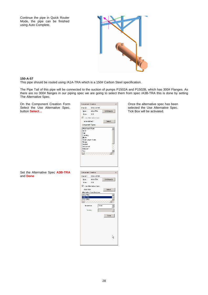
Continue the pipe in Quick Router Mode, the pipe can be finished using Auto Complete.
150-A-57 This pipe should be routed using /A1A-TRA which is a 150# Carbon Steel specification. The Pipe Tail of this pipe will be connected to the suction of pumps P1502A and P1502B, which has 300# Flanges. As there are no 300# flanges in our piping spec we are going to select them from spec /A3B-TRA this is done by setting The Alternative Spec. On the Component Creation Form Select the Use Alternative Spec. button Select…
Once the alternative spec has been selected the Use Alternative Spec. Tick Box will be activated.
Set the Alternative Spec A3B-TRA and Done

29
Once an alternative spec is selected you can toggle between the Branch Spec or Alternative Spec.
Create the Gasket and Flange at the Pipe Tail from the alternative spec.
Make sure you also tick the Use Alternative Spec box on the component creation form.
Exercise 3 (Completing the Pipework) Attempt the rest of the pipes in any order, your Trainer will offer assistance as required.
Exercise 4 (Replacing Components) In this exercise we will replace components using the Component Selection Form. Display Pipe /100-B-1 We will change the GATE valve indicated to a GLOBE Valve.
Select the Show pipe component select form Icon
Select the Globe valve (GLOB) the valve will be reselected. As the Globe Valve is a different size the Reconnection button is activated. To reconnect all the associated components select the Reconnection Button.
30
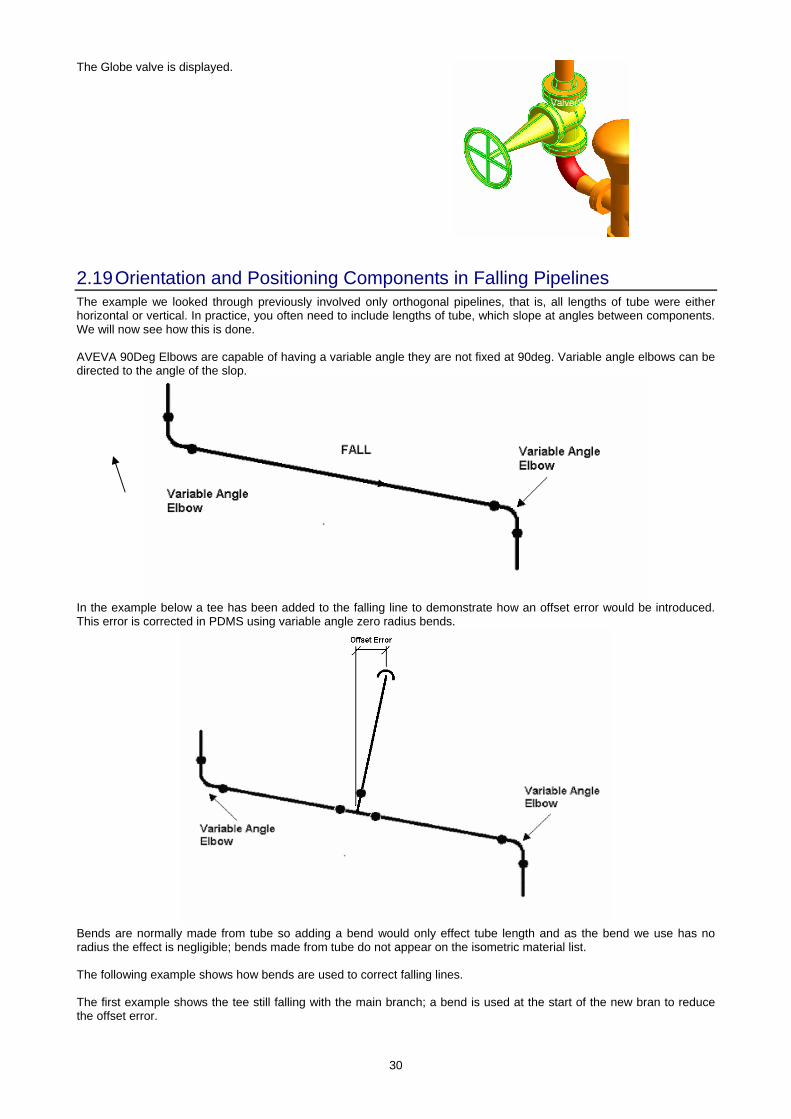
The Globe valve is displayed.
2.19 Orientation and Positioning Components in Falling Pipelines The example we looked through previously involved only orthogonal pipelines, that is, all lengths of tube were either horizontal or vertical. In practice, you often need to include lengths of tube, which slope at angles between components. We will now see how this is done. AVEVA 90Deg Elbows are capable of having a variable angle they are not fixed at 90deg. Variable angle elbows can be directed to the angle of the slop.
In the example below a tee has been added to the falling line to demonstrate how an offset error would be introduced. This error is corrected in PDMS using variable angle zero radius bends.
Bends are normally made from tube so adding a bend would only effect tube length and as the bend we use has no radius the effect is negligible; bends made from tube do not appear on the isometric material list. The following example shows how bends are used to correct falling lines. The first example shows the tee still falling with the main branch; a bend is used at the start of the new bran to reduce the offset error.
31
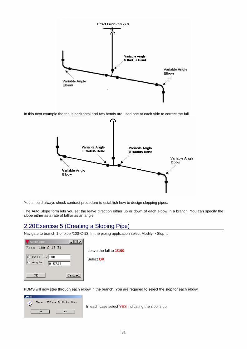
In this next example the tee is horizontal and two bends are used one at each side to correct the fall.
You should always check contract procedure to establish how to design slopping pipes. The Auto Slope form lets you set the leave direction either up or down of each elbow in a branch. You can specify the slope either as a rate of fall or as an angle.
2.20 Exercise 5 (Creating a Sloping Pipe) Navigate to branch 1 of pipe /100-C-13. In the piping application select Modify > Slop…
Leave the fall to 1/100 Select OK
PDMS will now step through each elbow in the branch. You are required to select the slop for each elbow.
In each case select YES indicating the slop is up.

32
As the pipe is open ended finishing at the battery limit the following form is displayed.
As we wish the pipe end to remain in the same place we will select NO
The pipe will now be slopping this can be checked using Query > General as we have done earlier. You should find the elbow direction to be of the form N 0.5729 U.
Exercise 6 (Controlling the Pipe Slope) We are now going to add a tee, a new branch and a bend to correct the slope of pipe /100-C-13 that we have just made slope. Add a Tee to 500mm from the 3rd elbow. Use the RH Mouse Pull Down so you can set it 500 from the change in direction
As you will remember from previous discussion the P3 leave direction of the tee will not be directly up. Create a new branch and connect the pipe head to the tee
The first item in this new branch must be a bend, Create a bend and select the Variable Angle and Radius bend in the choose form Set the Radius to Define and 0.00
Your branch should look like this.
We will now need to direct the bend up to remove the offset.

33
To direct the Bend up use Orientate > Component > Leave from the main top pull down.
Set the Direction to be U and tick the Change Angle Box.
Add an elbow and position it 1000mm from the Bend.
Use Orientate Component Slop to set the slop of the Elbow.
Set the Slop to Up and apply the Form Orientate>Component>Slope
The PL of the elbow will now be slopping if you check this the angle should be Direction N 0.5729 U.
34
2.21 Alternative Positioning Forms
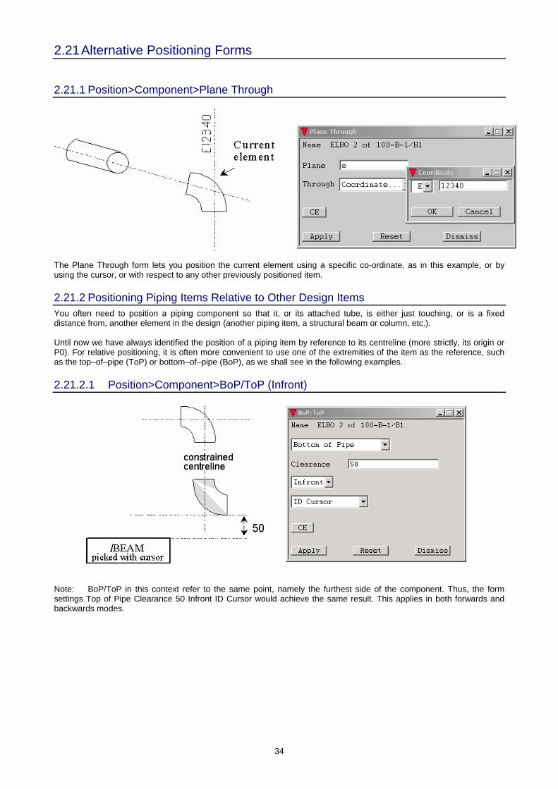
2.21.1 Position>Component>Plane Through
The Plane Through form lets you position the current element using a specific co-ordinate, as in this example, or by using the cursor, or with respect to any other previously positioned item.
2.21.2 Positioning Piping Items Relative to Other Design Items You often need to position a piping component so that it, or its attached tube, is either just touching, or is a fixed distance from, another element in the design (another piping item, a structural beam or column, etc.). Until now we have always identified the position of a piping item by reference to its centreline (more strictly, its origin or P0). For relative positioning, it is often more convenient to use one of the extremities of the item as the reference, such as the top–of–pipe (ToP) or bottom–of–pipe (BoP), as we shall see in the following examples.
2.21.2.1 Position>Component>BoP/ToP (Infront)
Note: BoP/ToP in this context refer to the same point, namely the furthest side of the component. Thus, the form settings Top of Pipe Clearance 50 Infront ID Cursor would achieve the same result. This applies in both forwards and backwards modes.
35
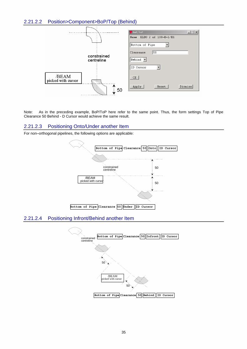
2.21.2.2 Position>Component>BoP/Top (Behind)
Note: As in the preceding example, BoP/ToP here refer to the same point. Thus, the form settings Top of Pipe Clearance 50 Behind - D Cursor would achieve the same result.
2.21.2.3 Positioning Onto/Under another Item For non–orthogonal pipelines, the following options are applicable:
/BEAMpicked with cursor
Bottom of Pipe Clearance 50 Onto ID Cursor
Bottom of Pipe Clearance 50 Under ID Cursor
50
50
constrainedcentreline
2.21.2.4 Positioning Infront/Behind another Item
/BEAMpicked with cursor
50
50
constrainedcentreline
Bottom of Pipe Clearance 50 Behind ID Cursor
Bottom of Pipe Clearance 50 Infront ID Cursor

36
2.21.2.5 Position>Component>Clearance (Infront)
Note: The form settings Clearance 50 Onto ID Cursor would achieve the same result in this example.
2.21.2.6 Position>Component>Clearance (Behind)
Note: The form settings Clearance 50 Under ID would achieve the same result in this example.
2.21.2.7 Positioning with Clearance Onto/Under another Item For non–orthogonal pipelines, the following options are applicable:
/BEAMpicked with cursor
Clearance 50 Onto ID Cursor
Clearance 50 Under ID Cursor
50
50
constrainedcentreline
37
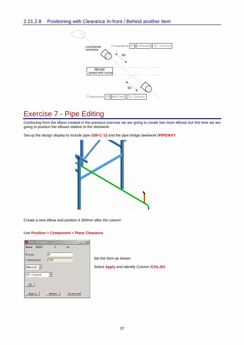
2.21.2.8 Positioning with Clearance In-front / Behind another Item
/BEAMpicked with cursor
Clearance 50 Infront ID Cursor
Clearance 50 Behind ID Cursor
50
50
constrainedcentreline
Exercise 7 - Pipe Editing Continuing from the elbow created in the previous exercise we are going to create two more elbows but this time we are going to position the elbows relative to the steelwork. Set-up the design display to include pipe /100-C-13 and the pipe bridge steelwork /PIPEWAY Create a new elbow and position it 300mm after the column Use Position > Component > Plane Clearance
Set the form as shown Select Apply and Identify Column /COL-B3
38
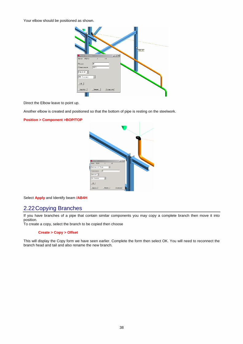
Your elbow should be positioned as shown.
Direct the Elbow leave to point up. Another elbow is created and positioned so that the bottom of pipe is resting on the steelwork. Position > Component >BOP/TOP
Select Apply and Identify beam /AB4H
2.22 Copying Branches If you have branches of a pipe that contain similar components you may copy a complete branch then move it into position. To create a copy, select the branch to be copied then choose Create > Copy > Offset This will display the Copy form we have seen earlier. Complete the form then select OK. You will need to reconnect the branch head and tail and also rename the new branch.
39
Chapter 3
3 Data Consistency Checker This Chapter shows you how to check the logical consistency of your design data, enabling you to find and correct the most common types of design error. You will normally carry out data consistency checks before you run the clash detection facilities. It is more convenient to do a data check on individual pipes than to do the whole Plant in one go. There may be too many errors to sort out at once.
3.1 Possible Types of Data Error The data consistency checking utility, available within DESIGN’s Piping and Structural applications, checks the following aspects of your design (piping examples shown):
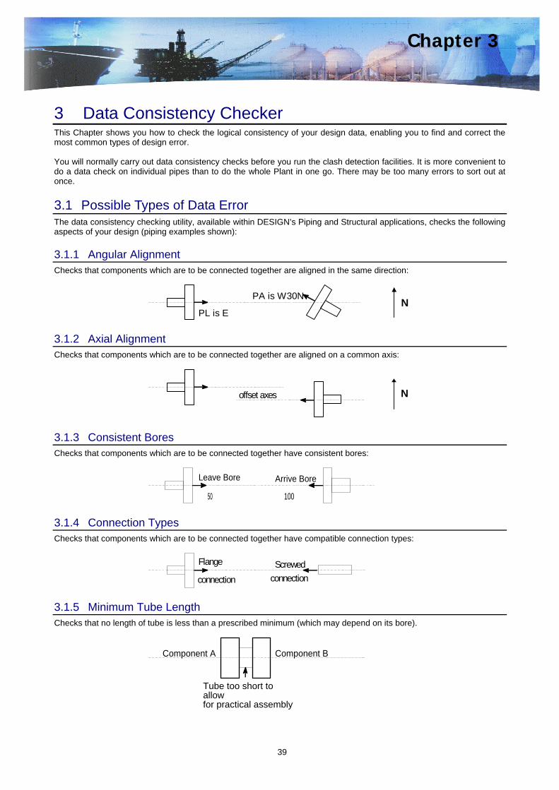
3.1.1 Angular Alignment Checks that components which are to be connected together are aligned in the same direction:
PL is E
PA is W30NN
3.1.2 Axial Alignment Checks that components which are to be connected together are aligned on a common axis:
offset axes N
3.1.3 Consistent Bores Checks that components which are to be connected together have consistent bores:
Leave Bore
50
Arrive Bore
100
3.1.4 Connection Types Checks that components which are to be connected together have compatible connection types:
Flange
connectionScrewed
connection
3.1.5 Minimum Tube Length Checks that no length of tube is less than a prescribed minimum (which may depend on its bore).
Component A Component B
Tube too short to allowfor practical assembly

40
3.2 Starting the Data Consistency Checks To carry out data consistency checking from within the Piping application, select Utilities>Data Consistency. You will see the following form:
By using this form, you can generate a diagnostic report on the data consistency of any part of your design. You may list the report on your screen (in the area in the lower half of the form), or you may send it to a file from which you can print a hard copy version. Select Terminal or File and, in the latter case, specify the directory and filename. Choose the hierarchic level at which you want to check the design using the Check list near top left of the form. The default is the current element. Specifying Parameters and Tolerances The data checking utility allows a margin of acceptable error before it diagnoses that you may have a problem. These built–in tolerances have default values, but you may set your own values if you prefer. As an example, by default your report will warn you of all lengths of tube in your design which are shorter than 100mm. This allows you to decide whether each such length is adequate for welding procedures, bolt withdrawal, access, and so on. You can change the acceptable minimum length from 100mm, and may set different minima for up to ten different pipe bore ranges if you wish. For example: A minimum length of 150mm for bores between 25 and 50. A minimum length of 300mm for bores between 50 and 100. To change any of the consistency check tolerances, use the appropriate Parameters button on the form (Piping for our current examples). You will see a subsidiary form on which you can change any of the current tolerances before carrying out the data checks.
3.3 Data Consistency Check Report Format The report comprises a header, giving the date and time, followed by an itemised list of the elements being checked, together with numbered diagnostic messages describing any potential problems. For example: DATE 11 FEBRUARY 99 TIME 14.12 PIPE /PIPE2 BRAN /PIPE2/B1 B 10 TAIL REFERENCE NOT SET END If no problems are found, you will see the message: *** NO DATA INCONSISTENCIES ***
41
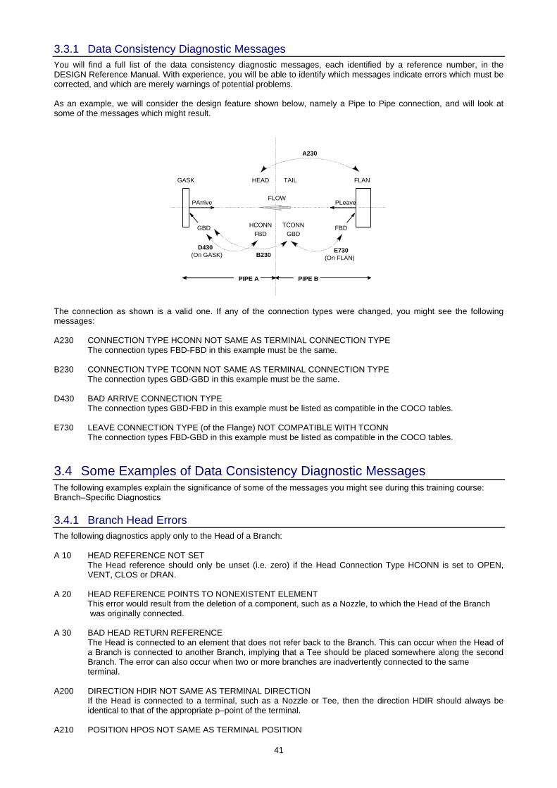
3.3.1 Data Consistency Diagnostic Messages You will find a full list of the data consistency diagnostic messages, each identified by a reference number, in the DESIGN Reference Manual. With experience, you will be able to identify which messages indicate errors which must be corrected, and which are merely warnings of potential problems. As an example, we will consider the design feature shown below, namely a Pipe to Pipe connection, and will look at some of the messages which might result.
HEAD TAIL
PIPE A PIPE B
GASK FLAN
FLOW
GBD HCONNFBD
TCONNGBD
FBD
D430(On GASK) B230
E730(On FLAN)
A230
PArrive PLeave
The connection as shown is a valid one. If any of the connection types were changed, you might see the following messages: A230 CONNECTION TYPE HCONN NOT SAME AS TERMINAL CONNECTION TYPE
The connection types FBD-FBD in this example must be the same.
B230 CONNECTION TYPE TCONN NOT SAME AS TERMINAL CONNECTION TYPE The connection types GBD-GBD in this example must be the same.
D430 BAD ARRIVE CONNECTION TYPE The connection types GBD-FBD in this example must be listed as compatible in the COCO tables.
E730 LEAVE CONNECTION TYPE (of the Flange) NOT COMPATIBLE WITH TCONN The connection types FBD-GBD in this example must be listed as compatible in the COCO tables.
3.4 Some Examples of Data Consistency Diagnostic Messages The following examples explain the significance of some of the messages you might see during this training course: Branch–Specific Diagnostics
3.4.1 Branch Head Errors The following diagnostics apply only to the Head of a Branch: A 10 HEAD REFERENCE NOT SET
The Head reference should only be unset (i.e. zero) if the Head Connection Type HCONN is set to OPEN, VENT, CLOS or DRAN.
A 20 HEAD REFERENCE POINTS TO NONEXISTENT ELEMENT
This error would result from the deletion of a component, such as a Nozzle, to which the Head of the Branch was originally connected.
A 30 BAD HEAD RETURN REFERENCE
The Head is connected to an element that does not refer back to the Branch. This can occur when the Head of a Branch is connected to another Branch, implying that a Tee should be placed somewhere along the second Branch. The error can also occur when two or more branches are inadvertently connected to the same terminal.
A200 DIRECTION HDIR NOT SAME AS TERMINAL DIRECTION
If the Head is connected to a terminal, such as a Nozzle or Tee, then the direction HDIR should always be identical to that of the appropriate p–point of the terminal.
A210 POSITION HPOS NOT SAME AS TERMINAL POSITION
42
If the Head is connected to a terminal, such as a Nozzle or Tee, then the position HPOS should always be identical to that of the appropriate p–point of the terminal.
A230 CONNECTION TYPE HCONN NOT SAME AS TERMINAL CONNECTION TYPE
If the Head is connected to a terminal, such as a Nozzle or Tee, then the connection type HCONN should always be identical to that of the appropriate p–point of the terminal.
A300 REFERENCE HSTUBE UNSET
There is more than 1mm of tube between the Head and the p–arrive of the first Component (or the Tail), but HSTUBE is unset.
A310 REFERENCE HSTUBE REFERS TO A NONEXISTENT SPCOM
This may occur if part of the Specification has been deleted.
A320 HSTUBE PROBLEM, CATREF IN SPCOM IS UNSET This indicates an error in the Specification.
A330 HSTUBE PROBLEM, CATREF IN THE SPCOM REFERS TO NONEXISTENT Catalogue COMPONENT This may occur if part of the Catalogue has been deleted or if the CATREF is unset.
A400 HBORE NOT SAME AS BORE OF HSTUBE The bore of any tube leading from the Head, determined from the Catalogue, should always be identical to
HBORE.
A410 HCON NOT COMPATIBLE WITH CONNECTION TYPE OF HSTUBE The connection type of any tube leading from the Head, determined from the Catalogue, should be compatible
with HCONN.
A420 ISPEC REFERENCE POINTS TO NONEXISTENT ELEMENT This error would occur if, for example, the Insulation Specification pointed to by ISPEC had been deleted.
3.4.2 Branch Tail Errors The same type of errors may occur to the Tail of a Branch. The message numbers are the same as for the Head errors but are preceded by a B. B 10 TAIL REFERENCE NOT SET
The Tail reference should only be unset (i.e. zero) if the Tail connection type TCONN is set to OPEN, VENT, CLOS or DRAN.
3.4.3 Plain Branch Errors The following diagnostics can occur only for Branches with no piping components: C500 TUBE TOO SHORT BETWEEN HEAD AND TAIL
The distance between the Head position, HPOS, and the Tail position, TPOS, is greater than zero and less than the specified minimum tube length (default: 100mm).
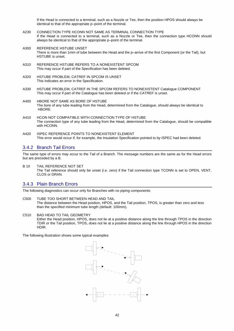
C510 BAD HEAD TO TAIL GEOMETRY
Either the Head position, HPOS, does not lie at a positive distance along the line through TPOS in the direction TDIR or the Tail position, TPOS, does not lie at a positive distance along the line through HPOS in the direction HDIR.
The following illustration shows some typical examples:

43
C520 HBORE NOT SAME AS TBORE When there are no components on the branch, the Head bore, HBORE, should be identical to the Tail bore,
TBORE.
C530 HCONN IS NOT COMPATIBLE WITH TCONN This implies that the Head is connected directly to the Tail with no Tube or piping components in between;
hence the Head connection type, HCONN, must be compatible with the Tail connection type, TCONN.
C540 THIS BRANCH HAS NO COMPONENTS This does not necessarily indicate an error. It is output as a warning.
3.4.4 Component–Specific Diagnostics The following errors apply to individual piping components and, in some cases, to their adjacent connections. Some of the errors also apply to Nozzles.
3.4.4.1 All–Component Diagnostics These are applicable to any component, regardless of its position in the network: D100 REFERENCE SPREF UNSET
This probably means that you have forgotten to choose the piping component correctly.
D300 CONN REFERENCE NOT SET Multi–way Components may be left unconnected only if the connection type of the relevant p–point is OPEN,
CLOS, VENT, DRAN or NULL.
D310 CONN REFERENCE POINTS TO NON–EXISTENT BRANCH This may occur if the Branch which is pointed to by the CONN reference has been deleted.
D320 BAD CONN RETURN REFERENCE This may occur if the Branch which is pointed to by the CONN reference has been reconnected to another terminal.
D400 ARRIVE TUBE LESS THAN TUBE MINIMUM. ACTUAL TUBE LENGTH IS ... The distance between the arrive p–point of this component and the leave p–point of the previous component
(or Head) is greater than zero and less than the specified minimum tube length (default: 100mm).
D410 BAD ARRIVE GEOMETRY The position and direction of the arrive p–point of this component are not correct with respect to the leave p–
point of the previous component (or Head). The error could be caused by incorrect positioning of this component, the previous component (or Head) or both.
The following illustration shows some typical examples:
D420 BAD ARRIVE BORE
The bore of the arrive p–point of this component is not equal to the bore of the preceding tube or, if this component is not preceded by tube, to the bore of the leave p–point of the previous component (or HBORE).
D430 BAD ARRIVE CONNECTION TYPE
The connection type of the arrive p–point of this component is not compatible with the preceding tube or, if this component is not preceded by tube, to the connection type of the leave p–point of the previous component (or HCONN).
D500 REFERENCE LSTUBE UNSET
You have probably forgotten to select the piping Component.
D600 LEAVE BORE NOT SAME AS BORE OF LSTUBE The bore of the leave p–point of this Component is not the same as the bore of the tube following the
Component.
44
D610 LEAVE CONNECTION TYPE NOT COMPATIBLE WITH CONNECTION TYPE OF LSTUBE The connection type of the leave p–point of this Component is not compatible with the tube following the
component.
3.4.5 End–Component Diagnostics These are applicable only to the last component in a Branch: E700 LEAVE TUBE LESS THAN TUBE MINIMUM. ACTUAL TUBE LENGTH IS ...
The distance between the leave p–point of the current component and the tail position, TPOS, is greater than zero and less than the specified minimum tube length (default: 100mm).
E710 BAD LEAVE GEOMETRY
The position and direction of the leave p–point of this component are not correct with respect to the position, TPOS, and direction, TDIR, of the tail. The error could be caused by incorrect positioning of this component, the Tail, or both.
E720 LEAVE BORE NOT SAME AS TBORE
The bore of the leave p–point of this component is not the same as the tail bore, TBORE.
E730 LEAVE CONNECTION TYPE NOT COMPATIBLE WITH TCONN The connection type of the leave p–point of this component is not compatible with the tail connection type
TCONN.
Exercise 8 (Data consistency check) Data consistency checks all the pipes you have created so far. Try to correct any inconsistencies. Continue building the rest of the pipework, checking each one as you build it.