avaya call management system - comtalk inc. call management system dell poweredge™ r720 and r620...
TRANSCRIPT

Avaya Call Management SystemDell PowerEdge™ R720 and R620 Computer Hardware Installation, Maintenance, and Troubleshooting
October 2015

© 2014-2015 Avaya Inc. All Rights Reserved.
NoticeWhile reasonable efforts have been made to ensure that the information in this document is complete and accurate at the time of printing, Avaya assumes no liability for any errors. Avaya reserves the right to make changes and corrections to the information in this document without the obligation to notify any person or organization of such changes.
Documentation disclaimer“Documentation” means information published by Avaya in varying mediums which may include product information, operating instructions and performance specifications that Avaya generally makes available to users of its products. Documentation does not include marketing materials. Avaya shall not be responsible for any modifications, additions, or deletions to the original published version of documentation unless such modifications, additions, or deletions were performed by Avaya. End User agrees to indemnify and hold harmless Avaya, Avaya's agents, servants and employees against all claims, lawsuits, demands and judgments arising out of, or in connection with, subsequent modifications, additions or deletions to this documentation, to the extent made by End User.
Link disclaimerAvaya is not responsible for the contents or reliability of any linked websites referenced within this site or documentation provided by Avaya. Avaya is not responsible for the accuracy of any information, statement or content provided on these sites and does not necessarily endorse the products, services, or information described or offered within them. Avaya does not guarantee that these links will work all the time and has no control over the availability of the linked pages.
WarrantyAvaya provides a limited warranty on its hardware and Software (“Product(s)”). Refer to your sales agreement to establish the terms of the limited warranty. In addition, Avaya’s standard warranty language, as well as information regarding support for this Product while under warranty is available to Avaya customers and other parties through the Avaya Support website: http://www.avaya.com/supportPlease note that if you acquired the Product(s) from an authorized Avaya reseller outside of the United States and Canada, the warranty is provided to you by said Avaya reseller and not by Avaya. “Software” means computer programs in object code, provided by Avaya or an Avaya Channel Partner, whether as stand-alone products or pre-installed on hardware products, and any upgrades, updates, bug fixes, or modified versions thereto.
LicensesTHE SOFTWARE LICENSE TERMS AVAILABLE ON THE AVAYA WEBSITE, http://support.avaya.com/LicenseInfo/ ARE APPLICABLE TO ANYONE WHO DOWNLOADS, USES AND/OR INSTALLS AVAYA SOFTWARE, PURCHASED FROM AVAYA INC., ANY AVAYA AFFILIATE, OR AN AUTHORIZED AVAYA RESELLER (AS APPLICABLE) UNDER A COMMERCIAL AGREEMENT WITH AVAYA OR AN AUTHORIZED AVAYA RESELLER. UNLESS OTHERWISE AGREED TO BY AVAYA IN WRITING, AVAYA DOES NOT EXTEND THIS LICENSE IF THE SOFTWARE WAS OBTAINED FROM ANYONE OTHER THAN AVAYA, AN AVAYA AFFILIATE OR AN AVAYA AUTHORIZED RESELLER; AVAYA RESERVES THE RIGHT TO TAKE LEGAL ACTION AGAINST YOU AND ANYONE ELSE USING OR SELLING THE SOFTWARE WITHOUT A LICENSE. BY INSTALLING, DOWNLOADING OR USING THE SOFTWARE, OR AUTHORIZING OTHERS TO DO SO, YOU, ON BEHALF OF YOURSELF AND THE ENTITY FOR WHOM YOU ARE INSTALLING, DOWNLOADING OR USING THE SOFTWARE (HEREINAFTER REFERRED TO INTERCHANGEABLY AS “YOU” AND “END USER”), AGREE TO THESE TERMS AND CONDITIONS AND CREATE A BINDING CONTRACT BETWEEN YOU AND AVAYA INC. OR THE APPLICABLE AVAYA AFFILIATE (“AVAYA”).
Avaya grants you a license within the scope of the license types described below, with the exception of Heritage Nortel Software, for which the scope of the license is detailed below. Where the order documentation does not expressly identify a license type, the applicable license will be a Designated System License. The applicable number of licenses and units of capacity for which the license is granted will be one (1), unless a different number of licenses or units of capacity is specified in the documentation or other materials available to you. “Designated Processor” means a single stand-alone computing device. “Server” means a Designated Processor that hosts a software application to be accessed by multiple users.
License type(s)Designated System(s) License (DS). End User may install and use each copy of the Software only on a number of Designated Processors up to the number indicated in the order. Avaya may require the Designated Processor(s) to be identified in the order by type, serial number, feature key, location or other specific designation, or to be provided by End User to Avaya through electronic means established by Avaya specifically for this purpose.
Concurrent User License (CU). End User may install and use the Software on multiple Designated Processors or one or more servers, so long as only the licensed number of Units are accessing and using the Software at any given time. A “Unit” means the unit on which Avaya, at its sole discretion, bases the pricing of its licenses and can be, without limitation, an agent, port or user, an e-mail or voice mail account in the name of a person or corporate function (e.g., webmaster or helpdesk), or a directory entry in the administrative database utilized by the Software that permits one user to interface with the Software. Units may be linked to a specific, identified Server.Named User License (NU). You may: (i) install and use the Software on a single Designated Processor or Server per authorized Named User (defined below); or (ii) install and use the Software on a Server so long as only authorized Named Users access and use the Software. “Named User”, means a user or device that has been expressly authorized by Avaya to access and use the Software. At Avaya’s sole discretion, a “Named User” may be, without limitation, designated by name, corporate function (e.g., webmaster or helpdesk), an e-mail or voice mail account in the name of a person or corporate function, or a directory entry in the administrative database utilized by the Software that permits one user to interface with the Software.Shrinkwrap License (SR). You may install and use the Software in accordance with the terms and conditions of the applicable license agreements, such as “shrinkwrap” or “clickthrough” license accompanying or applicable to the Software (“Shrinkwrap License”).
Heritage Nortel Software
“Heritage Nortel Software” means the software that was acquired by Avaya as part of its purchase of the Nortel Enterprise Solutions Business in December 2009. The Heritage Nortel Software currently available for license from Avaya is the software contained within the list of Heritage Nortel Products located at http://support.avaya.com/LicenseInfo/ under the link “Heritage Nortel Products”. For Heritage Nortel Software, Avaya grants Customer a license to use Heritage Nortel Software provided hereunder solely to the extent of the authorized activation or authorized usage level, solely for the purpose specified in the Documentation, and solely as embedded in, for execution on, or (in the event the applicable Documentation permits installation on non-Avaya equipment) for communication with Avaya equipment. Charges for Heritage Nortel Software may be based on extent of activation or use authorized as specified in an order or invoice.
Copyright Except where expressly stated otherwise, no use should be made of materials on this site, the Documentation, Software, or hardware provided by Avaya. All content on this site, the documentation and the Product provided by Avaya including the selection, arrangement and design of the content is owned either by Avaya or its licensors and is protected by copyright and other intellectual property laws including the sui generis rights relating to the protection of databases. You may not modify, copy, reproduce, republish, upload, post, transmit or distribute in any way any content, in whole or in part, including any code and software unless expressly authorized by Avaya. Unauthorized reproduction, transmission, dissemination, storage, and or use without the express written consent of Avaya can be a criminal, as well as a civil offense under the applicable law.
Third-party componentsCertain software programs or portions thereof included in the Software may contain software (including open source software) distributed under third party agreements (“Third Party Components”), which may contain terms that expand or limit rights to use certain portions of the Software (“Third Party Terms”). Information regarding distributed Linux OS source code (for those product that have distributed Linux OS source code) and identifying the copyright holders of the Third Party Components and the Third Party Terms that apply is available in the Documentation or on Avaya’s website at: http://support.avaya.com/ThirdPartyLicense/ You agree to the Third Party Terms for any such Third Party Components.
Preventing Toll Fraud“Toll fraud” is the unauthorized use of your telecommunications system by an unauthorized party (for example, a person who is not a corporate employee, agent, subcontractor, or is not working on your company's behalf). Be aware that there can be a risk of Toll Fraud associated with your system and that, if Toll Fraud occurs, it can result in substantial additional charges for your telecommunications services.
Avaya Toll Fraud interventionIf you suspect that you are being victimized by Toll Fraud and you need technical assistance or support, call Technical Service Center Toll Fraud Intervention Hotline at +1-800-643-2353 for the United States and Canada. For additional support telephone numbers, see the Avaya Support website: http://www.avaya.com/support. Suspected security vulnerabilities with Avaya products should be reported to Avaya by sending mail to: [email protected].

TrademarksThe trademarks, logos and service marks (“Marks”) displayed in this site, the Documentation and Product(s) provided by Avaya are the registered or unregistered Marks of Avaya, its affiliates, or other third parties. Users are not permitted to use such Marks without prior written consent from Avaya or such third party which may own the Mark. Nothing contained in this site, the Documentation and Product(s) should be construed as granting, by implication, estoppel, or otherwise, any license or right in and to the Marks without the express written permission of Avaya or the applicable third party.Avaya is a registered trademark of Avaya Inc.All non-Avaya trademarks are the property of their respective owners, and “Linux” is a registered trademark of Linus Torvalds.All other trademarks are the property of their respective owners.
Downloading documentsFor the most current versions of documentation, see the Avaya Support website:http://www.avaya.com/support
Contact Avaya SupportSee the Avaya Support website: http://support.avaya.com for product notices and articles, or to report a problem with your Avaya product.For a list of support telephone numbers and contact addresses, go to the Avaya Support website: http://support.avaya.com, scroll to the bottom of the page, and select Contact Avaya Support.


Avaya CMS Dell R720 and R620 Computer Hardware Installation October 2015 5
Chapter 1: Introduction . . . . . . . . . . . . . . . . . . . . . . . . . . . . . . . . . . . . . 7Purpose. . . . . . . . . . . . . . . . . . . . . . . . . . . . . . . . . . . . . . . . . . . . 7Intended audience . . . . . . . . . . . . . . . . . . . . . . . . . . . . . . . . . . . . . . 7Document changes since last issue . . . . . . . . . . . . . . . . . . . . . . . . . . . . 7Related resources . . . . . . . . . . . . . . . . . . . . . . . . . . . . . . . . . . . . . . 7
Documentation. . . . . . . . . . . . . . . . . . . . . . . . . . . . . . . . . . . . . . 7Avaya Mentor videos . . . . . . . . . . . . . . . . . . . . . . . . . . . . . . . . . . 8
Documentation websites . . . . . . . . . . . . . . . . . . . . . . . . . . . . . . . . . . 8Support . . . . . . . . . . . . . . . . . . . . . . . . . . . . . . . . . . . . . . . . . . . . 9
Chapter 2: Installation . . . . . . . . . . . . . . . . . . . . . . . . . . . . . . . . . . . . . 11Preparing for installation . . . . . . . . . . . . . . . . . . . . . . . . . . . . . . . . . . 12
Safety precautions. . . . . . . . . . . . . . . . . . . . . . . . . . . . . . . . . . . . 12System precautions . . . . . . . . . . . . . . . . . . . . . . . . . . . . . . . . . . . 13
Unpacking and inventorying the equipment . . . . . . . . . . . . . . . . . . . . . . . . 14Parts list . . . . . . . . . . . . . . . . . . . . . . . . . . . . . . . . . . . . . . . . . 15Determining the computer model. . . . . . . . . . . . . . . . . . . . . . . . . . . . 15Dell PowerEdge™ R720 . . . . . . . . . . . . . . . . . . . . . . . . . . . . . . . . . 15Dell PowerEdge™ R620 MID . . . . . . . . . . . . . . . . . . . . . . . . . . . . . . 16Dell PowerEdge™ R620 LOW . . . . . . . . . . . . . . . . . . . . . . . . . . . . . . 16Computer layout . . . . . . . . . . . . . . . . . . . . . . . . . . . . . . . . . . . . . 17Technical specifications . . . . . . . . . . . . . . . . . . . . . . . . . . . . . . . . 26
Mounting the Server Using the Rack Mount Kit . . . . . . . . . . . . . . . . . . . . . . 27Setting up power. . . . . . . . . . . . . . . . . . . . . . . . . . . . . . . . . . . . . . . 27Peripheral connectivity . . . . . . . . . . . . . . . . . . . . . . . . . . . . . . . . . . . 29Parts list . . . . . . . . . . . . . . . . . . . . . . . . . . . . . . . . . . . . . . . . . . . 30Avaya approved backup devices . . . . . . . . . . . . . . . . . . . . . . . . . . . . . . 31Support for KVM and headless CMS systems . . . . . . . . . . . . . . . . . . . . . . . 31Connecting the keyboard and mouse . . . . . . . . . . . . . . . . . . . . . . . . . . . 32Connecting the monitor . . . . . . . . . . . . . . . . . . . . . . . . . . . . . . . . . . . 32Connecting to external interfaces . . . . . . . . . . . . . . . . . . . . . . . . . . . . . 32
Connecting the switch link . . . . . . . . . . . . . . . . . . . . . . . . . . . . . . . 32Connecting to the customer network . . . . . . . . . . . . . . . . . . . . . . . . . 33Connecting the Customer Supplied SAS Tape Drive . . . . . . . . . . . . . . . . . 33
Turning on the system and verifying POST . . . . . . . . . . . . . . . . . . . . . . . . 33Turning the system over for provisioning . . . . . . . . . . . . . . . . . . . . . . . . . 33
Chapter 3: Maintenance . . . . . . . . . . . . . . . . . . . . . . . . . . . . . . . . . . . . . 35Precautions . . . . . . . . . . . . . . . . . . . . . . . . . . . . . . . . . . . . . . . . . 36
Contents

Contents
Avaya CMS Dell R720 and R620 Computer Hardware Installation October 2015 6
Turning the computer off and on . . . . . . . . . . . . . . . . . . . . . . . . . . . . . . 37Using an ESD wrist strap . . . . . . . . . . . . . . . . . . . . . . . . . . . . . . . . . . 37Maintaining disk drives . . . . . . . . . . . . . . . . . . . . . . . . . . . . . . . . . . . 38
Prerequisites . . . . . . . . . . . . . . . . . . . . . . . . . . . . . . . . . . . . . . . 38Required references . . . . . . . . . . . . . . . . . . . . . . . . . . . . . . . . . . . 38Replacing a disk drive . . . . . . . . . . . . . . . . . . . . . . . . . . . . . . . . . . 38
Maintaining tape drives . . . . . . . . . . . . . . . . . . . . . . . . . . . . . . . . . . . 39Cleaning the customer supplied tape drive . . . . . . . . . . . . . . . . . . . . . . 39
Connecting to external interfaces . . . . . . . . . . . . . . . . . . . . . . . . . . . . . 39Connecting the switch link . . . . . . . . . . . . . . . . . . . . . . . . . . . . . . . 40Connecting to the customer network . . . . . . . . . . . . . . . . . . . . . . . . . 40Connecting the tape drive. . . . . . . . . . . . . . . . . . . . . . . . . . . . . . . . 40
Connecting an optional SAS tape drive . . . . . . . . . . . . . . . . . . . . . . 40Turning on the system. . . . . . . . . . . . . . . . . . . . . . . . . . . . . . . . 40
Adding memory and replacing the CPU . . . . . . . . . . . . . . . . . . . . . . . . . . 41
Chapter 4: Troubleshooting. . . . . . . . . . . . . . . . . . . . . . . . . . . . . . . . . . . 43System messages . . . . . . . . . . . . . . . . . . . . . . . . . . . . . . . . . . . . . . 43Recovery procedures . . . . . . . . . . . . . . . . . . . . . . . . . . . . . . . . . . . . 44
Loss of power . . . . . . . . . . . . . . . . . . . . . . . . . . . . . . . . . . . . . . 44
Glossary . . . . . . . . . . . . . . . . . . . . . . . . . . . . . . . . . . . . . . . . . . . 45
Index . . . . . . . . . . . . . . . . . . . . . . . . . . . . . . . . . . . . . . . . . . . 47

Avaya CMS Dell R720 and R620 Computer Hardware Installation October 2015 7
Chapter 1: Introduction
PurposeThe document describes how to install, maintain, and troubleshoot Dell PowerEdge™ R720 and R620.
Note:Note: Dell PowerEdge™ R720 and R620 are compatible with Avaya Call Management
System (CMS) R17 for new installations and CMS R18 for upgrades.
Intended audienceThis document is intended for implementation engineers, support personnel, and system administrators who will install and maintain call center applications, such as CMS.
Document changes since last issueThe following change has been made to this document since the last issue:
● Identified that the Dell R720 and R620 are supported for upgrades to CMS R18.
Related resources
DocumentationSee the following documents.

Chapter 1: Introduction
8 Avaya CMS Dell R720 and R620 Computer Hardware Installation October 2015
Avaya Mentor videosAvaya Mentor is an Avaya-run channel on YouTube that includes technical content on how to install, configure, and troubleshoot Avaya products.
Go to http://www.youtube.com/AvayaMentor and perform one of the following actions:
● Enter a key word in the Search Channel to search for a specific product or topic.
● Scroll down Playlists, and click the name of a topic to see the available list of videos posted on the site.
Documentation websitesAll CMS documentation can be found at http://www.support.avaya.com. New issues of CMS documentation will be placed on this website when available.
Use the following websites to view related support documentation:
● Information about Avaya products and service
http://www.avaya.com
● Dell hardware documentation
http://www.dell.com
Table 1: Related documents
Title Use this document to:
Audience
Implementing
Avaya Call Management System Software Installation, Maintenance, and Troubleshooting for Linux
Install, maintain, and troubleshoot CMS on the Linux operating system.
Implementation engineers and system administrators

Support
Avaya CMS Dell R720 and R620 Computer Hardware Installation October 2015 9
SupportVisit the Avaya website at http://www.support.avaya.com for the most up-to-date documentation, product notices, and knowledge articles. You can also search for release notes, downloads, and resolutions to issues. Use the online service request system to create a service request. Chat with live agents to get answers to questions, or request an agent to connect you to a support team if an issue requires additional expertise.

Chapter 1: Introduction
10 Avaya CMS Dell R720 and R620 Computer Hardware Installation October 2015

Avaya CMS Dell R720 and R620 Computer Hardware Installation October 2015 11
Chapter 2: Installation
This section describes how to install the computer and related peripheral equipment. Use the following table to check off each required procedure after completion.
Procedure Completed
Preparing for installation on page 12
Unpacking and inventorying the equipment on page 14
Mounting the Server Using the Rack Mount Kit on page 27
Setting up power on page 27
Peripheral connectivity on page 29
Parts list on page 30
Avaya approved backup devices on page 31
Support for KVM and headless CMS systems on page 31
Connecting the keyboard and mouse on page 32
Connecting the monitor on page 32
Connecting to external interfaces on page 32
Turning on the system and verifying POST on page 33
Turning the system over for provisioning on page 33
Chapter 2: Installation
12 Avaya CMS Dell R720 and R620 Computer Hardware Installation October 2015
Preparing for installationThis section contains the following information that will help you prepare for the computer installation:
● Safety precautions on page 12
● System precautions on page 13
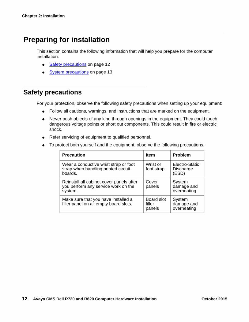
Safety precautionsFor your protection, observe the following safety precautions when setting up your equipment:
● Follow all cautions, warnings, and instructions that are marked on the equipment.
● Never push objects of any kind through openings in the equipment. They could touch dangerous voltage points or short out components. This could result in fire or electric shock.
● Refer servicing of equipment to qualified personnel.
● To protect both yourself and the equipment, observe the following precautions.
Precaution Item Problem
Wear a conductive wrist strap or foot strap when handling printed circuit boards.
Wrist or foot strap
Electro-Static Discharge (ESD)
Reinstall all cabinet cover panels after you perform any service work on the system.
Cover panels
System damage and overheating
Make sure that you have installed a filler panel on all empty board slots.
Board slot filler panels
System damage and overheating

Preparing for installation
Avaya CMS Dell R720 and R620 Computer Hardware Installation October 2015 13
System precautions
! WARNING:!
WARNING: DO NOT make mechanical or electrical modifications to the computer. Dell Computer Corp. is not responsible for regulatory compliance of modified computers.
Ensure that the voltage and frequency of the power outlet used matches the electrical rating labels on the equipment.
Wear antistatic wrist straps when handling any magnetic storage devices and printed circuit boards.
Each power supply uses nominal input voltages of 100-240 V AC at 50-60 Hz. The computer should be powered by an Uninterruptible Power Supply (UPS) or a non-switched, dedicated, 20-amp circuit. Dell products are designed to work with single-phase power systems having a grounded neutral conductor. To reduce the risk of electrical shock, do not plug Dell products into another type of power source. Contact your facilities manager or qualified electrician if you are unsure what type of power is supplied to your building.
A UPS provides a temporary electrical supply to a computer for several minutes, depending on the number of components connected to the UPS. For a CMS computer, a 1.5KVA minimum is required for each power supply. See your UPS documentation to determine the projected amount of backup battery time for your model. If the system is without power for longer than the backup time, the system may shut down improperly, and the customer could lose data.
Each of the following items requires a separate power cord:
● Computer
● External peripherals
● Monitor
Keep in mind the following:
● The room must have sufficient air conditioning capacity to support the cooling needs of the entire system.
● The air conditioning system must have controls that prevent excessive temperature.
Chapter 2: Installation
14 Avaya CMS Dell R720 and R620 Computer Hardware Installation October 2015
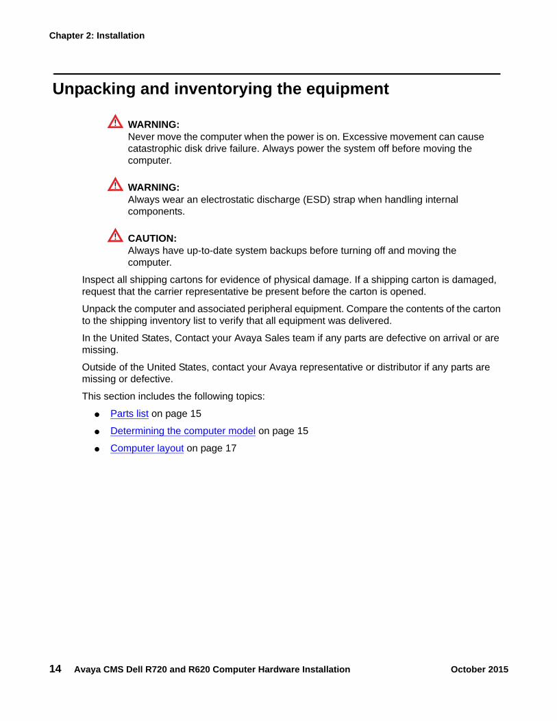
Unpacking and inventorying the equipment
! WARNING:!
WARNING: Never move the computer when the power is on. Excessive movement can cause catastrophic disk drive failure. Always power the system off before moving the computer.
! WARNING:!
WARNING: Always wear an electrostatic discharge (ESD) strap when handling internal components.
CAUTION:!
CAUTION: Always have up-to-date system backups before turning off and moving the computer.
Inspect all shipping cartons for evidence of physical damage. If a shipping carton is damaged, request that the carrier representative be present before the carton is opened.
Unpack the computer and associated peripheral equipment. Compare the contents of the carton to the shipping inventory list to verify that all equipment was delivered.
In the United States, Contact your Avaya Sales team if any parts are defective on arrival or are missing.
Outside of the United States, contact your Avaya representative or distributor if any parts are missing or defective.
This section includes the following topics:
● Parts list on page 15
● Determining the computer model on page 15
● Computer layout on page 17

Unpacking and inventorying the equipment
Avaya CMS Dell R720 and R620 Computer Hardware Installation October 2015 15
Parts listVerify that you have the following components before you begin installation:
● Computer and power cord
● Monitor, VGA cable, and monitor AC power cord
● USB keyboard and cable
● USB mouse and cable
● RedHat and CMS software
● Optional Backup device. See Avaya approved backup devices on page 31 for more information.
Determining the computer modelCMS R17.0 supports the Dell PowerEdge™ R720 MID, R620 MID and LOW computer models. See Dell PowerEdge™ R720 on page 15, Dell PowerEdge™ R620 MID on page 16, and Dell PowerEdge™ R620 LOW on page 16 for more information.
Dell PowerEdge™ R720
November 2013 model (used for new CMS R17 installations and upgrades to CMS R18)
● Two Intel® Xeon® E5-2620 2.00GHz 6-Core processors
● 64 GB RAM
● Twelve internal 300 GB SAS disks
● Internal DVD-RW disc drive
● Two hot-swappable 750 W AC power supplies
● RAID 10 system only
● One RAID controller card
● Can be used as a desktop unit or can be configured for rack mounting
● SAS HBA with external ports to support optional tape drive
● Optional backup device

Chapter 2: Installation
16 Avaya CMS Dell R720 and R620 Computer Hardware Installation October 2015
Dell PowerEdge™ R620 MID
May 2013 size model (used for new CMS R17 installations and upgrades to CMS R18)
● One Intel® Xeon® E5-2620 2.00GHz 6-Core processor
● 16 GB RAM
● Four internal 300 GB SAS disks
● Internal DVD-RW disc drive
● Two hot-swappable 495 W AC power supplies
● RAID 10 system only
● One RAID controller card
● Can be used as a desktop unit or can be configured for rack mounting
● SAS HBA w/external ports to support optional tape drive
● Optional backup device
Dell PowerEdge™ R620 LOW
May 2013 LOW-size model (used for new CMS R17 installations and upgrades to CMS R18)
● One Intel® Xeon® E5-2620 2.00GHz 6-Core processor
● 8 GB RAM
● One internal 300 GB SAS disk
● Internal DVD-RW disc drive
● One 495 W AC power supply
● No RAID or mirroring used
● Can be used as a desktop unit or can be configured for rack mounting
● SAS HBA w/external ports to support optional tape drive
● Optional backup device

Unpacking and inventorying the equipment
Avaya CMS Dell R720 and R620 Computer Hardware Installation October 2015 17
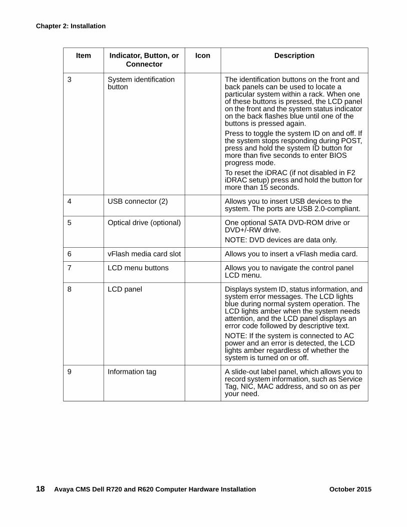
Computer layoutFamiliarize yourself with the layout of the computer.
Item Indicator, Button, or Connector
Icon Description
1 Power-on indicator, power button
The power-on indicator lights when the system power is on. The power button controls the power supply output to the system.Note: On ACPI-compliant operating systems, turning off the system using the power button causes the system to perform a graceful shutdown before power to the system is turned off.
2 NMI button Used to troubleshoot software and device driver errors when running certain operating systems. This button can be pressed using the end of a paper clip.Use this button only if directed to do so by qualified support personnel or by the operating system's documentation.
Dell R720 Front View
Chapter 2: Installation
18 Avaya CMS Dell R720 and R620 Computer Hardware Installation October 2015
3 System identification button
The identification buttons on the front and back panels can be used to locate a particular system within a rack. When one of these buttons is pressed, the LCD panel on the front and the system status indicator on the back flashes blue until one of the buttons is pressed again.Press to toggle the system ID on and off. If the system stops responding during POST, press and hold the system ID button for more than five seconds to enter BIOS progress mode.To reset the iDRAC (if not disabled in F2 iDRAC setup) press and hold the button for more than 15 seconds.
4 USB connector (2) Allows you to insert USB devices to the system. The ports are USB 2.0-compliant.
5 Optical drive (optional) One optional SATA DVD-ROM drive or DVD+/-RW drive. NOTE: DVD devices are data only.
6 vFlash media card slot Allows you to insert a vFlash media card.
7 LCD menu buttons Allows you to navigate the control panel LCD menu.
8 LCD panel Displays system ID, status information, and system error messages. The LCD lights blue during normal system operation. The LCD lights amber when the system needs attention, and the LCD panel displays an error code followed by descriptive text.NOTE: If the system is connected to AC power and an error is detected, the LCD lights amber regardless of whether the system is turned on or off.
9 Information tag A slide-out label panel, which allows you to record system information, such as Service Tag, NIC, MAC address, and so on as per your need.
Item Indicator, Button, or Connector
Icon Description

Unpacking and inventorying the equipment
Avaya CMS Dell R720 and R620 Computer Hardware Installation October 2015 19
10 Video connector Allows you to connect a VGA display to the system.
11 Hard drives Up to eight 2.5 inch hot-swappable hard drives.Up to four 2.5 hot-swappable hard drives and up to two 2.5 inch Dell PowerEdge Express Flash devices (PCIe SSDs).
Item Indicator, Button, or Connector
Icon Description

Chapter 2: Installation
20 Avaya CMS Dell R720 and R620 Computer Hardware Installation October 2015
Item Indicator, Button, or Connector
Icon Description
1 System identification button
The identification buttons on the front and back panels can be used to locate a particular system within a rack. When one of these buttons is pressed, the LCD panel on the front and the system status indicator on the back blink until one of the buttons is pressed again.Press to toggle the system ID on and off. If the system stops responding during POST, press and hold the system ID button for more than five seconds to enter BIOS progress mode.To reset iDRAC (if not disabled in F2 iDRAC setup) press and hold for more than 15 seconds.
2 System identification connector
Allows you to connect the optional system status indicator assembly through the optional cable management arm.
3 iDRAC7 Enterprise port
Dedicated management port.NOTE: The port is available for use only if the iDRAC7 Enterprise license is installed on your system.
4 Serial connector Allows you to connect a serial device to the system.
Dell R720 Rear View

Unpacking and inventorying the equipment
Avaya CMS Dell R720 and R620 Computer Hardware Installation October 2015 21
5 PCIe expansion card slot
Allows you to connect a PCIe expansion card.
6 Video connector Allows you to connect a VGA display to the system.
7 USB connectors (2) Allows you to connect USB devices to the system. The ports are USB 2.0-compliant.
8 Ethernet connectors (4)
Four integrated 10/100/1000 Mbps NIC connectorsorFour integrated connectors:
● Two integrated 10/100/1000 Mbps NIC connectors
● Two integrated 100 Mbps/1 Gbps/10 Gbps SFP+ connectors
9 PCIe expansion card slot
Allows you to connect a PCIe expansion card.
10 Power supply (PSU1)
AC 495W, 750W or 1100W
11 Power supply (PSU2)
AC 495W, 750W or 1100W
Item Indicator, Button, or Connector
Icon Description

Chapter 2: Installation
22 Avaya CMS Dell R720 and R620 Computer Hardware Installation October 2015
Item Indicator, Button, or Connector
Icon Description
1 Power-on indicator, power button
The power-on indicator lights when the system power is on. The power button controls the power supply output to the system.Note: On ACPI-compliant operating systems, turning off the system using the power button causes the system to perform a graceful shutdown before power to the system is turned off.
2 NMI button Used to troubleshoot software and device driver errors when running certain operating systems. This button can be pressed using the end of a paper clip.Use this button only if directed to do so by qualified support personnel or by the operating system's documentation.
3 System identification button
The identification buttons on the front and back panels can be used to locate a particular system within a rack. When one of these buttons is pressed, the LCD panel on the front and the system status indicator on the back flashes blue until one of the buttons is pressed again.Press to toggle the system ID on and off. If the system stops responding during POST, press and hold the system ID button for more than five seconds to enter BIOS progress mode.To reset the iDRAC (if not disabled in F2 iDRAC setup) press and hold the button for more than 15 seconds.
4 USB connector (2) Allows you to insert USB devices to the system. The ports are USB 2.0-compliant.
Dell R620 Front View

Unpacking and inventorying the equipment
Avaya CMS Dell R720 and R620 Computer Hardware Installation October 2015 23
5 Optical drive (optional) One optional SATA DVD-ROM drive or DVD+/-RW drive. NOTE: DVD devices are data only.
6 vFlash media card slot Allows you to insert a vFlash media card.
7 LCD menu buttons Allows you to navigate the control panel LCD menu.
8 LCD panel Displays system ID, status information, and system error messages. The LCD lights blue during normal system operation. The LCD lights amber when the system needs attention, and the LCD panel displays an error code followed by descriptive text.NOTE: If the system is connected to AC power and an error is detected, the LCD lights amber regardless of whether the system is turned on or off.
9 Information tag A slide-out label panel, which allows you to record system information, such as Service Tag, NIC, MAC address, and so on as per your need.
10 Video connector Allows you to connect a VGA display to the system.
11 Hard drives (8) Up to eight 2.5 inch hot-swappable hard drives.Up to four 2.5 hot-swappable hard drives and up to two 2.5 inch Dell PowerEdge Express Flash devices (PCIe SSDs).
Item Indicator, Button, or Connector
Icon Description

Chapter 2: Installation
24 Avaya CMS Dell R720 and R620 Computer Hardware Installation October 2015
Item Indicator, Button, or Connector
Icon Description
1 System identification button
The identification buttons on the front and back panels can be used to locate a particular system within a rack. When one of these buttons is pressed, the LCD panel on the front and the system status indicator on the back blink until one of the buttons is pressed again.Press to toggle the system ID on and off. If the system stops responding during POST, press and hold the system ID button for more than five seconds to enter BIOS progress mode.To reset iDRAC (if not disabled in F2 iDRAC setup) press and hold for more than 15 seconds.
2 System identification connector
Allows you to connect the optional system status indicator assembly through the optional cable management arm.
3 iDRAC7 Enterprise port
Dedicated management port.NOTE: The port is available for use only if the iDRAC7 Enterprise license is installed on your system.
4 Serial connector Allows you to connect a serial device to the system.
5 PCIe expansion card slot (riser 2)
Allows you to connect a PCIe expansion card.
6 Video connector Allows you to connect a VGA display to the system.
7 USB connectors (2) Allows you to connect USB devices to the system. The ports are USB 2.0-compliant.
Dell R620 Rear View

Unpacking and inventorying the equipment
Avaya CMS Dell R720 and R620 Computer Hardware Installation October 2015 25
8 Ethernet connectors (4)
Four integrated 10/100/1000 Mbps NIC connectorsorFour integrated connectors:
● Two integrated 10/100/1000 Mbps NIC connectors
● Two integrated 100 Mbps/1 Gbps/10 Gbps SFP+ connectors
9 PCIe expansion card slot (riser 3)
Allows you to connect a PCIe expansion card.
10 Power supply (PSU1)
AC 495W, 750W or 1100W
11 Power supply (PSU2)
AC 495W, 750W or 1100W
Item Indicator, Button, or Connector
Icon Description

Chapter 2: Installation
26 Avaya CMS Dell R720 and R620 Computer Hardware Installation October 2015
Technical specifications
Device name Description
Monitor
Power Consumption ● Normal operation - 17 W● Switch off - Less than 0.5 W
Dimensions (with stands)
● Height 380.6 mm (14.98 inches) ● Width 374.5 mm (14.74 inches) ● Depth 59.0 mm (2.32 inches)
Dimensions (without stands)
● Height 307.0 mm (12.09 inches) ● Width 374.5 mm (14.74 inches) ● Depth 59.0 mm (2.32 inches)
Weight (with stand assembly and cables)
4.31 kg (9.5 lb)
Weight (without stand assembly)
3.04 kg (6.7 lb)For wall mount or VESA mount considerations - no cables
Operating Temperature
5° to 35° C (41° to 95°F)
Operating Humidity 10% to 80% (non-condensing)
Thermal dissipation ● 86.2 BTU/hour (maximum) ● 58.6 BTU/hour (typical)
Keyboard
Dimensions ● Height 3/4 inches● Width 18 inches● Depth 5-5/8 inches
R620 System (LOW and MID)
Dimensions ● Height 42.8 mm (1.68 inches) ● Width 482.4 mm (18.99 inches) with rack latches and 434 mm
(17.08 inch) without rack latches● Depth 700.5 mm (27.58 inches) of eight-hard-drive systems
Weight 18.58 kg (40.96 lbs) of eight-hard-drive systems
VA Rating 6.5 A X 110 VAC = 715 VA

Mounting the Server Using the Rack Mount Kit
Avaya CMS Dell R720 and R620 Computer Hardware Installation October 2015 27
Mounting the Server Using the Rack Mount KitFor more information about mounting the Dell R720 server using sliding rails, see ftp://ftp.dell.com/Manuals/all-products/esuprt_ser_stor_net/esuprt_poweredge/poweredge-r710_Setup%20Guide4_en-us.pdf.
For more information about mounting the Dell R620 server using the Rack Mount Kit, see http://support.dell.com/support/edocs/systems/peR620/en/placemat/rack/r620pmrack.pdf.
Setting up powerTo set up the AC power:
Nominal Power Consumption
6.5 A - 3 A (X 2) (with 495 W AC power supply unit)
Heat Output 1908 BTU/hr maximum (495 W power supply)
Operating Temperature
Continuous operation: 10 °C to 35 °C. De-rate maximum allowable dry bulb temperature at 1 °C/300 m above 900 m (1°F /550 ft)
Humidity 10% to 80% relative humidity (RH), with 26 °C maximum dew point
R720 System
Dimensions ● Height 87.3 mm● Width 482.4 mm with rack latches and 444 mm without rack
latches● Depth 723 mm
Weight 29.5kg (64.9lbs)
VA Rating 10.0 A X 110 VAC = 1100 VA
Nominal Power Consumption
10.0A - 5 A (X 2) (with 750 W AC power supply unit)
Heat Output 2891 BTU/hr maximum (750 W power supply)
Operating Temperature
Continuous operation: 10 °C to 35 °C. De-rate maximum allowable dry bulb temperature at 1 °C/300 m above 900 m (1°F /550 ft)
Humidity 10% to 80% relative humidity (RH), with 26 °C maximum dew point
Device name Description
Chapter 2: Installation
28 Avaya CMS Dell R720 and R620 Computer Hardware Installation October 2015
1. Plug the IEC end of the power cord in to the AC outlet.
For installations outside of the United States and Canada, obtain a power cord for your local configuration.
2. Plug the power cord from the computer into an outlet on the UPS if a UPS is available.
A UPS provides a temporary electrical supply to a computer for several minutes, depending on the number of components connected to the UPS. For a CMS computer, a 1.5KVA minimum is required for each power supply. See your UPS documentation to determine the projected amount of backup battery time for your model. If the system is without power for longer than the backup time, the system may shut down improperly, and the customer could lose data.
If a UPS is not being used, you must use a grounded outlet on a minimum 15-amp circuit.
! Important:Important: Do not turn on power at this time.

Peripheral connectivity
Avaya CMS Dell R720 and R620 Computer Hardware Installation October 2015 29
Peripheral connectivityThe following diagram shows in general how equipment connects to the computer. The callouts are described in Parts list on page 30.
Chapter 2: Installation
30 Avaya CMS Dell R720 and R620 Computer Hardware Installation October 2015
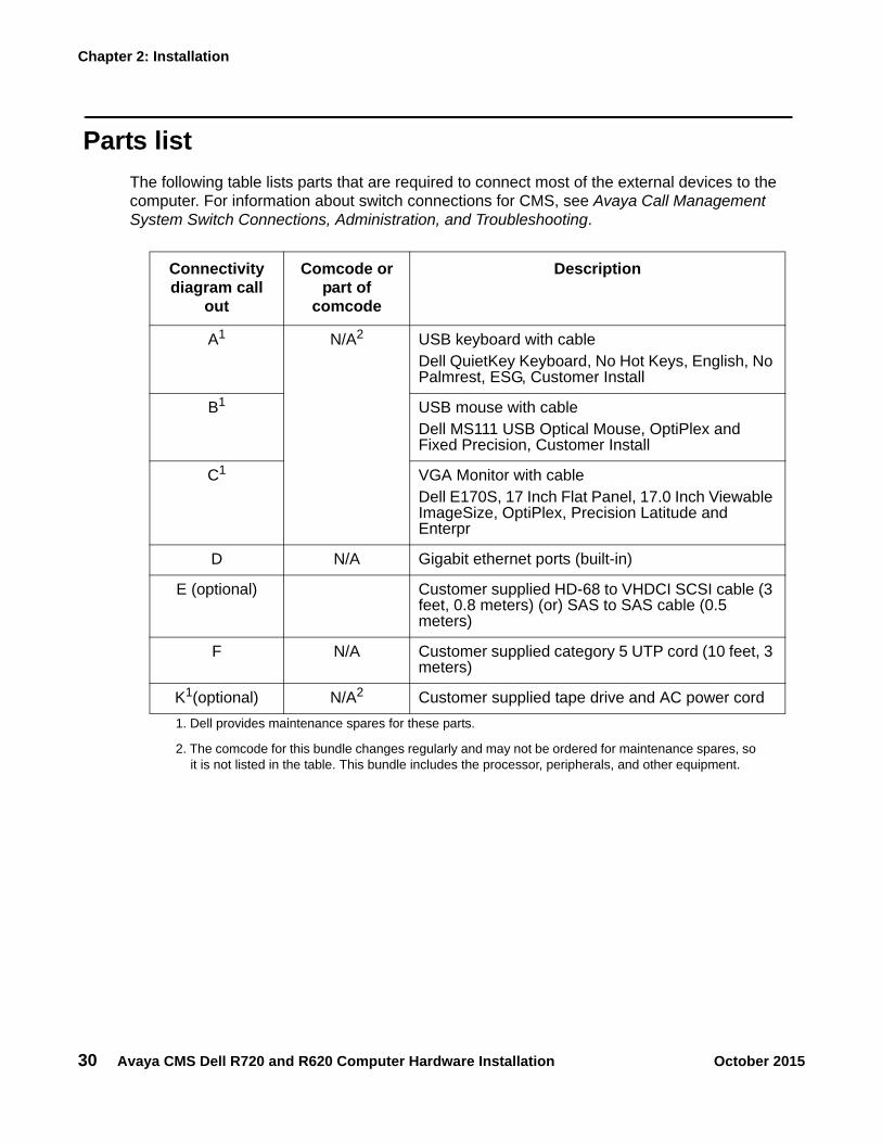
Parts listThe following table lists parts that are required to connect most of the external devices to the computer. For information about switch connections for CMS, see Avaya Call Management System Switch Connections, Administration, and Troubleshooting.
Connectivity diagram call
out
Comcode or part of
comcode
Description
A1
1. Dell provides maintenance spares for these parts.
N/A2
2. The comcode for this bundle changes regularly and may not be ordered for maintenance spares, so it is not listed in the table. This bundle includes the processor, peripherals, and other equipment.
USB keyboard with cableDell QuietKey Keyboard, No Hot Keys, English, No Palmrest, ESG, Customer Install
B1 USB mouse with cableDell MS111 USB Optical Mouse, OptiPlex and Fixed Precision, Customer Install
C1 VGA Monitor with cableDell E170S, 17 Inch Flat Panel, 17.0 Inch Viewable ImageSize, OptiPlex, Precision Latitude and Enterpr
D N/A Gigabit ethernet ports (built-in)
E (optional) Customer supplied HD-68 to VHDCI SCSI cable (3 feet, 0.8 meters) (or) SAS to SAS cable (0.5 meters)
F N/A Customer supplied category 5 UTP cord (10 feet, 3 meters)
K1(optional) N/A2 Customer supplied tape drive and AC power cord
Avaya approved backup devices
Avaya CMS Dell R720 and R620 Computer Hardware Installation October 2015 31
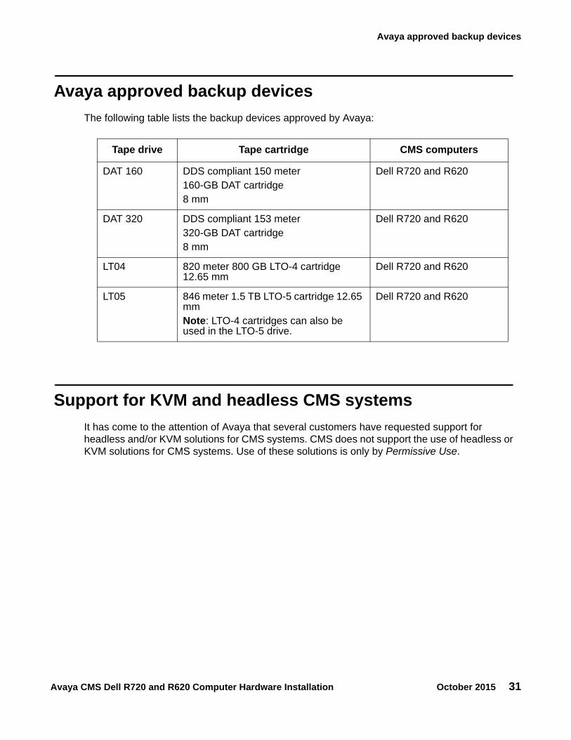
Avaya approved backup devicesThe following table lists the backup devices approved by Avaya:
Support for KVM and headless CMS systemsIt has come to the attention of Avaya that several customers have requested support for headless and/or KVM solutions for CMS systems. CMS does not support the use of headless or KVM solutions for CMS systems. Use of these solutions is only by Permissive Use.
Tape drive Tape cartridge CMS computers
DAT 160 DDS compliant 150 meter160-GB DAT cartridge8 mm
Dell R720 and R620
DAT 320 DDS compliant 153 meter320-GB DAT cartridge8 mm
Dell R720 and R620
LT04 820 meter 800 GB LTO-4 cartridge 12.65 mm
Dell R720 and R620
LT05 846 meter 1.5 TB LTO-5 cartridge 12.65 mmNote: LTO-4 cartridges can also be used in the LTO-5 drive.
Dell R720 and R620

Chapter 2: Installation
32 Avaya CMS Dell R720 and R620 Computer Hardware Installation October 2015
Connecting the keyboard and mouseConnect the keyboard and mouse to the USB ports.
Connecting the monitor1. Connect the power cord from the monitor to the UPS or wall outlet.
2. Connect the VGA cable to the VGA connection at the rear of the system and connect the opposite end to the VGA port on the Monitor.
Connecting to external interfacesThis section describes the external interfaces connected to the computer. This section includes the following topics:
● Connecting the switch link on page 32.
● Connecting to the customer network on page 33.
● Connecting the Customer Supplied SAS Tape Drive on page 33.
Connecting the switch linkThe CMS computer uses TCP/IP over a local area network (LAN) at only 10/100 Mbps for a connection to the switch. One CMS computer can collect data from several switches. To the CMS computer, each switch represents one ACD.
You must use ethernet port 1 for this connection.
For detailed information about how to connect and administer the switch link, see Avaya Call Management System Switch Connections, Administration, and Troubleshooting.

Turning on the system and verifying POST
Avaya CMS Dell R720 and R620 Computer Hardware Installation October 2015 33
Connecting to the customer networkThe computer supports built-in ethernet ports that support network speeds of 10/100/1000 Mbps. However, for CMS installations, you must use only speeds of 10/100 Mbps. This ethernet connection is used for CMS Supervisor, network printers, and LAN backup.
You must use ethernet port 0 for this connection.
Connecting the Customer Supplied SAS Tape DriveThe customer supplied Serial Attached SCSI (SAS) cable connects one of the SAS ports in PCIe on the back of the computer to the SAS port on the rear of the customer supplied tape drive.
Turning on the system and verifying POSTOnce you assemble the system, including the loose hardware that is shipped with the system that you installed with help from CMS Provisioning, turn on the system and verify the results of the Power-On Self Test (POST).
To turn on the system and verify POST:
1. Plug the power cord of the UPS into an AC outlet.
2. Turn on the power to the UPS.
3. Turn on tape drive.
4. Turn on the system monitor.
5. Press and release the power button.
6. The system boots.
Turning the system over for provisioningAfter completing the physical installation of the system, the installation continues with software provisioning. This is often done with the support of the Avaya CMS Provisioning group. Provisioning the system consists of the following:
● Setting up CMS

Chapter 2: Installation
34 Avaya CMS Dell R720 and R620 Computer Hardware Installation October 2015
● Authorizing features
● Adding logins and passwords
● Testing the software
● Setting up system alarming
To continue with provisioning, see the chapter “Turning the system over to the customer” in the CMS Software Installation, Maintenance, and Troubleshooting document for your CMS release.
Avaya CMS Dell R720 and R620 Computer Hardware Installation October 2015 35
Chapter 3: Maintenance
This section describes the following maintenance procedures:
● Precautions on page 36
● Turning the computer off and on on page 37
● Using an ESD wrist strap on page 37
● Maintaining disk drives on page 38
● Maintaining tape drives on page 39
● Connecting to external interfaces on page 39
● Adding memory and replacing the CPU on page 41

Chapter 3: Maintenance
36 Avaya CMS Dell R720 and R620 Computer Hardware Installation October 2015
Precautions
! DANGER:!
DANGER: Hazardous energy levels are present inside the system when the system remains connected to a power source. Be sure to follow the safety procedures in the owner's guide or service manual.
! WARNING:!
WARNING: Before replacing any component in the system, you must turn off the computer and disconnect the AC power cord.
CAUTION:!
CAUTION: Printed circuit boards and hard disk drives contain electronic components that are extremely sensitive to static electricity. Ordinary amounts of static from your clothes or the work environment can destroy components. Do not touch the components or any metal parts without taking proper antistatic precautions. See Using an ESD wrist strap on page 37 for more information.
CAUTION:!
CAUTION: Avoid keeping the cover off for extended periods of time while the system is operating. The cover must be installed to prevent automatic thermal shutdown.
! Important:Important: For security purposes, CMS R17 and later releases include a CMS hardware
authorization feature. During the initial CMS feature authorization process, the system preserves information about the configuration and hardware of the CMS system. The system periodically checks the changes to the motherboard, IP address, or MAC address. If the system detects differences between the preserved CMS hardware information and the current CMS hardware information, the CMS hardware feature is reset to not authorized. This forces the auth_set command to be re-run. If at any time the system displays a message that the auth_set command needs to be run, then the customer must contact Avaya Services personnel to run the auth_set command. The auth_set command requires a password that is only available to authorized Avaya personnel. Once the auth_set command has been re-run, the system preserves the new CMS hardware information.
To minimize downtime the customer must make arrangements with Avaya personnel to run the auth_set command prior to performing any of the following changes to the system:
● Replacing a motherboard
● Changing the IP address of the CMS system

Turning the computer off and on
Avaya CMS Dell R720 and R620 Computer Hardware Installation October 2015 37
● Restoring a Virtual CMS
Turning the computer off and onUse the following procedures to turn the computer off and on.
To turn off the computer:1. Log in to the system as root.
2. Enter:
/usr/sbin/shutdown -h now
This shuts down the system.
3. Turn off the system monitor.
4. Turn off any external devices, starting with the device that is closest to the system and working toward the farthest device.
To turn on the computer:1. Turn on any external devices, starting with the device that is farthest from the system and
working toward the system.
2. Turn on the system monitor.
3. Press and release the power button.
If the system is operating properly, a banner screen is displayed within about 5 minutes after it is turned on.
4. Log in to the system as root.
Using an ESD wrist strapBefore you work on components inside the computer:
1. Make sure that the computer is plugged in to AC power.
2. Make sure that the power is off.
3. Attach the Electro-Static Discharge (ESD) wrist strap to the chassis frame and to your wrist.
4. Unplug the AC power cord.

Chapter 3: Maintenance
38 Avaya CMS Dell R720 and R620 Computer Hardware Installation October 2015
Maintaining disk drivesThis section includes the following topics:
● Prerequisites on page 38
● Required references on page 38
● Replacing a disk drive on page 38
PrerequisitesIf possible, do a CMSADM backup before you add or replace a disk drive. See your CMS Software Installation, Maintenance, and Troubleshooting document for this procedure.
Required referencesThe following references are required when doing procedures in this section:
● The CMS Software Installation, Maintenance, and Troubleshooting document for your CMS release.
● Dell PowerEdge™ R720 Server and Dell PowerEdge™ R620 Server at the Dell documentation Web site:
http://www.dell.com
Replacing a disk driveThis procedure describes how to replace a disk drive.
To remove a disk drive:
Note:Note: This procedure should be followed multiple times if replacing multiple disk drives.
1. Dell SAS disks are hot-swappable. However, if the customer has the LOW system, it only has one disk. So you cannot apply hot-swapping to LOW systems. Follow the instructions in Software Installation, Maintenance, and Troubleshooting for your version of CMS to complete the procedures before removal of the disk.
2. Locate the disk drive to be removed. A map of drive locations is located on the front right side of the system.
3. Press the drive button to release the drive latch.
Maintaining tape drives
Avaya CMS Dell R720 and R620 Computer Hardware Installation October 2015 39
4. Pull firmly on the drive latch to slide the drive out of the drive bay.
5. Set the drive aside on an antistatic mat.
6. Remove the replacement hard drive from its shipping container and antistatic packaging.
7. Press the drive button to release the drive latch.
8. Orient the hard drive with the drive latch towards you, and the label facing up.
9. Carefully slide the drive into the drive bay by pressing on the area between the drive button and the drive status LEDs.
10. When you feel resistance, press firmly so that the drive latch begins to close.
11. Press the drive latch closed.
Maintaining tape drivesThis section includes the following topics:
● Cleaning the customer supplied tape drive on page 39
Cleaning the customer supplied tape driveThis section describes how to clean the tape drive.
Note:Note: CMS computers do not ship with tape drive cleaning tapes. Customers using tape
backup must purchase at least one cleaning tape as soon as the computer is installed and in service. The number of cleaning cycles available on a cleaning cartridge depends on the manufacturer of the cartridge. You must clean the tape regularly to maximize tape drive performance. You must clean the tape drive once a week or every five (5) data backups, whichever comes first.
To clean the tape drive, follow the instructions in the manufacturers documentation for the tape drive the customer purchased.
Connecting to external interfacesThis section describes the external interfaces connected to the computer. This section includes the following topics:
● Connecting the switch link on page 40.

Chapter 3: Maintenance
40 Avaya CMS Dell R720 and R620 Computer Hardware Installation October 2015
● Connecting to the customer network on page 40.
● Connecting the tape drive on page 40.
Connecting the switch linkThe CMS computer uses TCP/IP over a local area network (LAN) at only 10/100 Mbps for a connection to the switch. One CMS computer can collect data from several switches. To the CMS computer, each switch represents one ACD.
You must use ethernet port 1 for this connection.
For detailed information about how to connect and administer the switch link, see Avaya Call Management System Switch Connections, Administration, and Troubleshooting.
Connecting to the customer networkThe computer supports built-in ethernet ports that support network speeds of 10/100/1000 Mbps. However, for CMS installations, Avaya recommends that you only use speeds at the 10/100 Mbps speed range. This ethernet connection is used for CMS Supervisor, network printers, and LAN backup.
You must use ethernet port 0 for this connection.
Connecting the tape driveConnections to the tape drive are for the Dell R720 and Dell R620 platform only.
Connecting an optional SAS tape drive
A Serial Attached SCSI (SAS) cable connects from the SAS port located on the back of the computer to the SAS port on the back of the tape drive.
Turning on the system
To turn on the system:
1. Connect the power cord from the tape drive to a power source.
2. Turn on the tape drives, starting with the tape drive that is farthest from the system and working toward the system.
3. Turn on the system monitor.

Adding memory and replacing the CPU
Avaya CMS Dell R720 and R620 Computer Hardware Installation October 2015 41
4. Press and release the power button.
Adding memory and replacing the CPUDell technicians, Avaya technicians, or Avaya business partner technicians can upgrade and repair memory and CPU. Contact Avaya support or your business partner if your system needs any upgrades or repairs.

Chapter 3: Maintenance
42 Avaya CMS Dell R720 and R620 Computer Hardware Installation October 2015

Avaya CMS Dell R720 and R620 Computer Hardware Installation October 2015 43
Chapter 4: Troubleshooting
This section describes the following troubleshooting procedures:
● System messages on page 43
● Recovery procedures on page 44
Additional troubleshooting: See the Dell PowerEdge™ R720 Owner's Manual at the following Dell web site for additional troubleshooting procedures:
http://downloads.dell.com/Manuals/Common/poweredge-r720_Owner's%20Manual_en-us.pdf
See the Dell PowerEdge™ R620 Owner's Manual at the following Dell web site for additional troubleshooting procedures:
http://support.dell.com/support/edocs/systems/peR620/en/om/r620omen.pdf
System messagesSystem messages can alert you to system problems, such as a device that is about to fail. By default, many of the messages are displayed on the system console and are stored in /var/log.
To display system messages:
1. Enter:
dmesg
The system displays the most recent messages as shown in the following example:
Wed Feb 14 11:01:59 MST 2001Feb 14 08:19:20 tern pseudo: [ID 129642 kern.info] pseudo-device: tod0Feb 14 08:19:20 tern genunix: [ID 936769 kern.info] tod0 is /pseudo/tod@0Feb 14 08:19:22 tern syslogd: going down on signal 15.................................Feb 16 14:24:08 tern scsi: [ID 365881 kern.info] /pci@1f,0/pci@1/scsi@1,1/st@5,:Feb 16 14:24:08 tern <HP DDS-4 DAT (Sun)>Feb 16 14:24:08 tern scsi: [ID 193665 kern.info] st12 at glm1: target 5 lun 0Feb 16 14:24:08 tern genunix: [ID 936769 kern.info] st12 is /pci@1f,0/pci@1/scs0Feb 19 10:17:59 tern automountd[198]: [ID 784820 daemon.error] server cortex nogFeb 19 10:18:27 tern last message repeated 6 times

Chapter 4: Troubleshooting
44 Avaya CMS Dell R720 and R620 Computer Hardware Installation October 2015
The /var/log directory contains several message files. The most recent messages are in /var/log/messages. Previous system messages are organized into weekly message files and are identified by the date that is appended to the messages file.
The message files may contain not only system messages, but also crash dumps and other data, which can cause /var/log to grow quite large. To keep the directory to a reasonable size and ensure that future crash dumps can be saved, you should remove unneeded files periodically. You can automate the task by using crontab. See your Linux® system documentation for information on crontab.
Recovery proceduresThis section provides solutions for the following problems:
● Loss of power on page 44
Loss of powerIf the system loses power, it is recommended (but not required) that you empty the disc drive and tape drives. The system boots from the disk by default.
To turn on the computer:1. Turn on all external devices.
2. Turn on the system monitor.
3. Press and release the power button.
To turn off the computer:1. Log in to the system as root.
2. Enter:
/usr/sbin/shutdown -h now
This shuts down the system.
3. Turn off the system monitor.
4. Turn off all external devices.
Avaya CMS Dell R720 and R620 Computer Hardware Installation October 2015 45
Glossary
Automatic Call Distribution (ACD)
A switch feature. ACD is software that channels high-volume incoming call traffic to agent groups (splits or skills).Also an agent state where the extension is engaged in an ACD call (with either the agent talking to the caller or the call waiting on hold).
Boot disk A disk that contains the Linux® operating system and customer data.CMS Call Management System (CMS). A software product used by business
customers that have an Avaya telecommunications switch and receive a large volume of telephone calls that are processed through the Automatic Call Distribution (ACD) feature of the switch.
FB- DIMM Dual In-line Memory Module. A narrow printed circuit board that holds memory chips. It plugs into a FB-DIMM socket on the motherboard or memory board.
IDE Integrated Drive ElectronicsNon-Volatile Random Access Memory (NVRAM)
A random access memory (RAM) system that holds its contents when external power is lost.
SAS Serial Attached SCSI.SCSI See Small Computer System Interface (SCSI).SCSI Bus An industry standard peripheral bus that is used to connect intelligent
peripherals to a computer. It uses a daisy-chained cabling arrangement that originates at the Host Adapter to interconnect up to seven intelligent peripheral controllers on the bus. The Dell computer uses a fast SCSI-2 implementation.
SCSI ID Each tap on the SCSI bus is required to have a unique identification or address, which is the SCSI ID. The ID is set by a push button located on each device.
SCSI Single-Ended Bus
A version of the SCSI bus designed to minimize cost and space. Cable lengths up to 6 meters are supported. A SCSI single-ended bus is not compatible with the differential version of the SCSI bus.
Small Computer System Interface (SCSI)
A hardware interface that allows the connection of devices (such as hard disks) to a computer system.
SSO Services Support Organization. The Avaya organization that provides technical support for Avaya products.

SSO
46 Avaya CMS Dell R720 and R620 Computer Hardware Installation October 2015

Avaya CMS Dell R720 and R620 Computer Hardware Installation October 2015 47
Index
Index
Aadding
memory . . . . . . . . . . . . . . . . . . . . 41Avaya approved backup devices . . . . . . . . . . 31
Bback panel . . . . . . . . . . . . . . . . . . . . 17
Ccleaning tape drives . . . . . . . . . . . . . . . . 39connecting
AC power cord . . . . . . . . . . . . . . . . . 27external interfaces . . . . . . . . . . . . . . . 32
Connecting the Customer Supplied SAS Tape Drive . 33connectivity diagram . . . . . . . . . . . . . . . . 30
Ddetermining the model . . . . . . . . . . . . . . . 16disk drive
maintenance . . . . . . . . . . . . . . . . . . 38
EESD precautions. . . . . . . . . . . . . . . . . . 37
Ffront panel. . . . . . . . . . . . . . . . . . . . . 17
GGlossary . . . . . . . . . . . . . . . . . . . . . 45
Hhelplines . . . . . . . . . . . . . . . . . . . . . . 9
Iinstallation checklist . . . . . . . . . . . . . . . . .11
Lloss of power . . . . . . . . . . . . . . . . . . . . 44
Mmaintenance
cleaning tape drives . . . . . . . . . . . . . . . 39disk drives . . . . . . . . . . . . . . . . . . . 38tape drives . . . . . . . . . . . . . . . . . . . 39
memory . . . . . . . . . . . . . . . . . . . . . . 41models. . . . . . . . . . . . . . . . . . . . . . . 15
OOpenBoot
PROM firmware tests . . . . . . . . . . . . . . 43
Pparts list . . . . . . . . . . . . . . . . . . . . 15, 30power cord . . . . . . . . . . . . . . . . . . . . . 27power supply . . . . . . . . . . . . . . . . . . . . 27precautions . . . . . . . . . . . . . . . . 12, 13, 37preparing for the installation . . . . . . . . . . . . . 12preserving data after a system failure . . . . . . . . 44
Rrecovery procedures . . . . . . . . . . . . . . . . 44
loss of power . . . . . . . . . . . . . . . . . . 44preserving data after a system failure . . . . . . . 44
Ssafety precautions . . . . . . . . . . . . . . . . . 12system precautions . . . . . . . . . . . . . . . . . 13
Ttape drive
maintenance . . . . . . . . . . . . . . . . . . 39troubleshooting
OpenBoot PROM firmware tests . . . . . . . . . 43preserve data after a system failure. . . . . . . . 44
turning off the computer . . . . . . . . . . . . . . . 37

48 Avaya CMS Dell R720 and R620 Computer Hardware Installation October 2015
Index
turning on the computer . . . . . . . . . . . . . . 37turning the system over for provisioning . . . . . . . 33