available in carbon and stainless steel 80 - cast spa · available in carbon and stainless steel...
TRANSCRIPT

261
Prodotto in ACCiAio AL CArBonioe in ACCiAio inossidABiLeAVAILABLE IN CARBON AND STAINLESS STEEL
80

262
ORIGINS OF THE PRESS FITTINGTo fully understand the innovative content of the new Series C4 it is necessary to analyze the theory of operation of the traditional Series 70….. often named the “Italian version”, which has been on the market for several decades without any substantial innovation.
In the Series 70…. the mechanism of connection between the flexible tube, the fitting for the tube and the sleeve to crimp was basically split into two different parts faced separately: the fastening of the flexible tube and the seal of the fluid.
In the external part the crimping of the sleeve (both skive and no-skive) would allow the barbs of the sleeve to make contact with the metal threads of the rubber tube to create the fastening between the sleeve, the rubber tube and the fitting body in order to stop pull-out under pressure. In addition the crushing of the sleeve, in the internal part of the coupling, allowed the barb of the fitting body with its stepped geometry to collapse and occupy the substrate of the rubber tube to seal potential leakages.
In practical terms in the traditional project three different components are featured (separate sleeve, tube and fitting body), which solve the two problems of fastening and sealing independently from each other. Given a geometry that is substantially identical in the sleeve barb and the fitting body, while pressing, the sleeve carries out the crimping of the tube and simply compresses the tube on the barbs of the fitting body to provide the necessary seal. Nevertheless the natural deformation of the sleeve only follows the logic of fastening to the tube and the compression of the mate-rial is in charge of creating the seal.So we have a situation where the two problems are treated as one consequent to the other or vice versa, without a real integrated solution.
The innovative idea is not to deal with the two issues in a separate manner but rather as a single integrated project so to optimise the possible synergies.
The project, as shown in the drawings, was started to fine a definitive solution to both requirements by integrating the various characteristics in order to obtain a unique and definitive solution to implement the technical improvements offered by engineering.
For this reason the interlocking geometry of the sleeve is much more performing, as it uses the geometry of the barb of the fitting body to guarantee a better fastening, creating an important safety synergy; on the other hand, the geometry of the fitting body, not being stressed by the compression of the crimping, increases the sealing of the substrate, which is less mechanically strained; at the same time, the wave shape obtained absorb vibrations, a typical problem of this type of application, thus significantly reducing the wear of the system in general.
To obtain this result, if on one side it was necessary to dimension the barbs and their position on the fitting body so to guarantee a perfect interchangeability with the previous product, the dimensions, the angles and the positioning of the sleeve barbs have required an in-depth study to obtain the perfect interlocking system between the two geome-tries after the deformations of the crimping. In fact, far from being equally distributed, the barbs of the different sle-eve families, and also those in the same family but with different diameters, have been carefully positioned to obtain the mentioned result,researching the perfect positioning once crimping is done.
To complete the project, the “stop-tube” technical solution was applied to all the newly manufactured sleeves to make the assembly more user friendly.

263
The Mission
ACCIDENT PREVENTION•
ENVIRONMENTAL PROTECTION•
PRODUCT RESPONSIBILITY•
ENERGY CONSUMPTION REDUCTION•
LEAKAGE-FREE TUBE ASSEMBLIES•
OIL-LESS ASSEMBLIES•
SYSTEM CONTROL IN CASE OF HARSHWORKING CONDITIONS:
PRESSURE, VIBRATIONS AND HIGHTEMPERATURES
MARKET REQUIREMENTS:DUST-DRY SEALING
SIMPLE AND CONSOLIDATED ASSEMBLYRECOGNISABLE PRODUCT

264
The Target
The evolution of the press fitting system for high pressure flexible tubes, with a scheduled plan of
research, development, innovation and industrialisation of the product, finalised to obtain the international industrial patent.
•Leakage and oil free connections even in
especially harsh working conditions in terms of pressure, vibrationsand high temperatures,
within the set limits.•
Improvement of the seal by creating a construction geometry thatincreases the number of contact points in the substrate of the rubber
tube to be sufficient to obtain a dust dry seal.•
Consolidated assembly made without complications using the same tools used for the existing assembly.
•Widespread distribution on the market of the new press fitting for
high pressure flexible tubes of the Series C4, reliable, pull-outresistant, with a constructive technology, providing state-of-the-art
safe crimping.•
Full product traceability via traceability coding.•
Full interchangeability with products existing on the market.•
Customer satisfaction.•
Possible use with carbon and stainless steel.•
Rationalised use of resources for an improved social impact.

265
The Benefits
SAFETYTube pull-out resistance thanks to the clinching system.
•Dust dry sealing due to more sealing points.
•Vibration absorption thanks to variable wave geometry.
•Product traceability via traceability coding.
TECHNICSComplete interchangeability with products existing on the market.
•Assembly carried out with normally used tools.
•Possible use with carbon and stainless steel.
COSTSPeace of mind for having used one of the best technologies
in the industry.•
Preventing accidents to people, the environment, systems andthe image of the company.
•Contributing to containing the national energy deficit.
•Safeguarding the environment and the quality of life in the country
for future generations.•
International patent pending.

266
Page 277 Page 22-277 Page 23 Page 24 Page 25-26 Page 27÷32 Page 33; 276÷292
Page 293 Page 293 Page 294 Page 294 Page 295 Page 295 Page 296
Page 296 Page 297 Page 298 Page 299 Page 300 Page 301 Page 302
Page 303 Page 304 Page 305 Page 306 Page 306 Page 307 Page 308
Page 308 Page 309 Page 309 Page 310 Page 310 Page 311 Page 311
Page 312 Page 313 Page 314 Page 314 Page 315 Page 316 Page 316
Page 317 Page 317 Page 318 Page 318 Page 319 Page 320 Page 321
Page 321 Page 322 Page 323 Page 323 Page 324 Page 324 Page 325
Page 325 Page 326 Page 326 Page 326 Page 327 Page 327 Page 327
Page 327 Page 328 Page 329 Page 330 Page 330 Page 331 Page 331
FIGURATIVE INDEX – FITTINGS SAE J516 - ISO 12151
General instructions
Utilisationstandards
Qualityassurance
Safetyfactors
Allowedtemperatures
Sealson threads
Finishtreatments
End treatments
Tubesto be used
Tablesfollow up
Threadedends
Gas – Metric UNF - NPT
Prescriptions to comply with
Assembly instructions
Code: 8001 ..1SN-R1AT – 2SCskive
Code: 8002 ..2SN-R2ATskive
Code: 8003 ..1SN-R1AT - 2SCno skive
Code: 8004 ..2SN-R2ATno skive
Code: 8005..1SN-R1AT - 2SN-R2AT2SC no skive
Code: 8005..-COMP1SCno skive
Code: 8006 ..4SP-4SHskive
Code: 8008..R7 - R7TMno skive
Code: 8009..24° series L/S
Code: 8010..24° series L/S
Code: 8011..24° series L/S
Code: 8013..Standpipe series L/S
Code: 8014..Standpipe series L/S
Code: 8015..Standpipe series L/S
Code: 8016..JIC 37°
Code: 8018..JIC 37°
Code: 8018..JIC 37°
Code: 8019..JIC 37°
Code: 8020..JIC 37°
Code: 8020..JIC 37°
Code: 8021..JIC 37°
Code: 8022..JIC 37°
Code: 8023..JIC 37°
Code: 8023..JIC 37°
Code: 8024..BSPT 60°
Code: 8025..NPTF 60°
Code: 8026..BSPP 60°
Code: 8027..BSPP 60°
Code: 8028..BSPP 60°
Code: 8028..BSPP 60°
Code: 8029..BSPP 60°
Code: 8030..BSPP 60°
Code: 8030..BSPP 60°
Code: 8031..BSPP 60°
Code: 8032..BSPP 60°
Code: 8033..BSPP 60°
Code: 8035..Metric Parallel 60°
Code: 8036..Metric Parallel 60°
Code: 8036..Metric Parallel 60°
Code: 8037..Metric Parallel 60°
Code: 8038..Metric Parallel 60°
Code: 8039..Metric Parallel 60°
Code: 8041..Metric Parallel 60°
Code: 8038..Metric Parallel 60°
Code: 8040..Metric Parallel 60°
Code: 8011..24° series L/SCode: 8012..24° series L/S
Code: 8017..JIC 37°
Code: 8033..BSPP 60°
Code: 8034..Metric Parallel 60°
Code: 8041..Metric Parallel 60°
Code: 8045..ORFD
Code: 8042.. ORFD
Code: 8046.. GasCode: 8047.. Metric
Code: 8043..ORFD
Code: 8048.. GasCode: 8049.. Metric
Code: 8043..ORFD
Code: 8050..Series 3000
Code: 8044..ORFD
Code: 8051..Series 3000
Code: 8044..ORFD
Code: 8052..Series 3000
Code: 8045..ORFD
Code: 8053..Series 6000

267
Page 332 Page 333Page 332 Page 334 Page 334 Page 335 Page 335
Page 336 Page 336 Page 337 Page 337 Page 337 Page 338 Page 338
Page 338 Page 338 Page 339 Page 339 Page 340 Page 340 Page 340
Page 341 Page 341 Page 341 Page 341 Page 342 Page 342 Page 342
Page 343 Page 343 Page 343 Page 343 Page 344 Page 344 Page 345
Page 345 Page 346 Page 346 Page 347 Page 347 Page 347
Page 280 Page 280 Page 281 Page 281 Page 282 Page 282 Page 282
Page 283 Page 283 Page 284 Page 284 Page 285 Page 285 Page 348
Page 348 Page 348 Page 348 Page 349 Page 350 Page 351 Page 351
Page 351 Page 352÷356 Page Page Page Page Page
Page 347
FIGURATIVE INDEX – FITTINGS SAE J516 - ISO 12151Code: 8054..Series 6000
Code: 8055..Series 6000
Code: 8056.. S 3000Code: 8057.. S 6000
Code: 8058.. Interlock4SH - 4SP - R13
Code: 8059.. InterlockR13
Code: 8060.. Interlock24° series L/S
Code: 8061.. Interlock24° series L/S
Code: 8062 .. Interlock24° series L/S
Code: 8063 .. Interlock24° series L/S
Code: 8064 .. InterlockJIC 37°
Code: 8065 .. InterlockJIC 37°
Code: 8066 .. InterlockJIC 37°
Code: 8066 .. InterlockJIC 37°
Code: 8067.. InterlockJIC 37°
Code: 8067.. InterlockJIC 37°
Code: 8069.. InterlockNPTF
Code: 8070.. InterlockBSPP 60°
Code: 8071.. InterlockBSPP 60°S
Code: 8071.. InterlockBSPP 60°
Code: 8072.. InterlockBSPP 60°
Code: 8072.. InterlockBSPP 60°
Code: 8073.. InterlockBSPP 60°
Code: 8073.. InterlockBSPP 60°
Code: 8074.. InterlockORFS
Code: 8075.. InterlockORFS
Code: 8075.. InterlockORFS
Code: 8076.. InterlockORFS
Code: 8076.. InterlockORFS
Code: 8077.. InterlockORFS
Code: 8077.. InterlockORFS
Code: 8078.. InterlockSeries 3000
Code: 8079.. InterlockSeries 3000
Code: 8080.. InterlockSeries 3000
Code: 8081.. InterlockSeries 6000
Code: 8082.. InterlockSeries 6000
Code: 8083.. InterlockSeries 6000
Code: 8086..Quick connection
Code: 7301..EN 853/1SNSAE 100 R1AT
Code: 7302..EN 853/2SNSAE 100 R2AT
Code: 7305..EN 857 1SC
Code: 7306..EN 857 2SC
Code: 7315..1SC HIGH PRESSURE WATER JET WASHERSBLUE COVER
Code: 7317..2SC HIGH PRESSURE WATER JET WASHERSBLUE COVER
Code: 7314..1SC HIGH PRESSURE WATER JET WASHERSBLACK COVER
Code: 7316..2SC HIGH PRESSURE WATER JET WASHERSBLACK COVER
Code: 8065 .. InterlockJIC 37°
Code: 8068.. InterlockBSPT
Code: 8084..Quick connection
Code: 8085..Quick connection
Code: 7308..EN 856/4SP
Code: STM-80..CONTROL SWIVELS
Code: 7309..EN 856/4SH
Code: STSICONTROL SWIVELS
Code: 7310..EN 856/R13
Code: 0301.. NBRCode: 0302.. VitonO-RING
Code: 7311..EN 855 R7SAE 100 R7
Code: 0303.. 0304.. NBRCode: 0305.. 0306.. VitonGASKETS
Code: 7312..R7TM
Code: 0023.. CarbonCode: 0123.. St. steelCONT. RING
Code: STT-80..CONTROL SWIVELS
Code: 0220.. GasCode: 0221.. MetricCOPPER RING
Code: STS-80..CONTROL SWIVELS
Code: 0320.. GasCode: 0321.. MetricBONDED RING
Compatiblefluidstable
Code: 8087..Quick connection

Series C4
Material carbon steel
Straight with slip-on nut
24° cone, tube 15L, flexible tube DN 1 O
8 0 10 19
Series C4
Material carbon steel
Straight with stapled nut
60° cone 3/8” gas, flexible tube DN 1 O
8 0 27 09
Series C4
Material carbon steel
45° curve with stapled nut
60° cone 1/2” gas, flexible tube DN 12
8 0 32 12
Series C4
Material carbon steel
90° curve with stapled nut
60° cone 3/4” gas, flexible tube DN 19
8 0 29 17
268
HOSE FITTINGS• If you require a stud coupling with slip-on nut,24° cone or with O-Ring, 0 tube 15L, thread nut M22x1.5, for flexible tube DN10, order:801019
• If you require to order the chosen fitting made ofstainless steel, replace the number 80 with 81 in the initial code 801019
DELIVERIES
• Cast S.p.A. fittings are delivered in the configurations shown in the tables of this catalogue.• Available on scheduled orders only: it means that the article is slow moving and will be delivered within 90 days.• Available on request only: it means that the article is not commonly in stock; please contact our offices for further delivery details.
ORDERING EXAMPLES (Carbon steel)
ORDERING EXAMPLES (Stainless steel)
HOSE FITTINGS• If you require a stud coupling with BSPP 3/8” stapled nut, for flexible tube DN1 O and 60° cone, order: 802709
• If you require to order the chosen fitting made ofstainless steel, replace the number 80 with 81in the initial code, order: 812709
HOSE FITTINGS• If you require a 45°fitting with BSPP 1/2” stapled nut, for flexible tube DN12 and 60° cone, order 803212
• If you require the chosen stainless steel fitting, replace the number 80 with 81 in the initial code 813212
HOSE FITTINGS• If you require a 90°fitting with BSPP 3/4” stapled nut, for flexible tube DN19 and 60° cone, order: 802917
• If you require the chosen stainless steel fitting, replace the number 80 with 81 in the initial code 812917

269
HOSE FITTINGSCOUPLING SYSTEM
Fitting bodycollapse
Referenceprescriptions:
Rubber hoseEN 853 1SNSAE 100 R1AT
Final sweat-proofseal
Ferrule forhose 1SN-R1ATSkive
Hose fittingwith stapled nutISO 12151
60° coneBS 5200
Crimpednut
THEORY OF OPERATION (skive ferrule)
The CAST fitting for flexible hose of the Series C4 is a press fitting with multiple seal to be assembled on the hydraulic rubber hose compliant with EN 853, EN 856, EN 857, SAE J517 to obtain system connections. It helps fast assembly of removable hoses in the configurations needed to create complex high-performance oleo-dynamic systems.
While pressing the ferrule, its geometrical configuration compresses the external metal reinforcement of the flexible hose, enga-ging perfectly with the female geometry of the fitting body to obtain a perfect crimping of the components and increase the per-formance considerably.
Traceabilitydecoding:
= Logo of theManufacturer
• T =Production plant
• 3 =Year of manufacture
• CE =Made in EEC
• 50 =Type of steel used
• 01 =Heat numberof the steel used

270
TECHNICAL CHARACTERISTICS (skive sleeve)
The CAST fitting for flexible hose of the Series C4 guarantees perfect tightness of the circuit regardless of the fluid used, provided that corrosive fluids are avoided and the nominal pressures and temperatures specified by the manufacturer are complied with. The male-female clinching system creates an innovative, state-of-the-art locking system that guarantees environmental protection and the safety of people and objects.
Normal vibrations do not alter the fitting’s performance, which, even at maximum values, retains its characteristics of absolute reliability. The rubber hose to be assembled on the fittings must be strictly suitable for hydraulic applications, while it must be underlined that the hydraulic hoses with fittings have a limited life.
TECHNICAL INNOVATION
For many years now there has been an increasing imperative market demand for fluid system components that guarantee three main factors:
SAFETy EASy ASSEMBLy LEAKAGE-FREE TIGHTNESS
These features, these days needed for the environmental and workplace safety (Leg. Decree 81/2008), as well as for product responsibility (Presidential Decree 224-EEC 85/374) and for the integrated ecological protection system have led us to develop this new series of products with the tube stop, adjustable geometry in the assembly phase, interlocking clinching and increased sealing points in the rubber substrate and the seal of the tube output from the sleeve.
Before pressing the sleeve on the peeled hose
After pressing the sleeve on the peeled hose
Sealing points 1-2-3-4
Pressure surfaces IIII 6-9Sealing points 5-7-8-10(on each single barb) Sealing points 11-12
Fitting body collapse
Multiple seal male-female crimping:Safety gUARANTEE - Protecting the ENVIRONMENT - Enhancing the PERFORMANCE
271
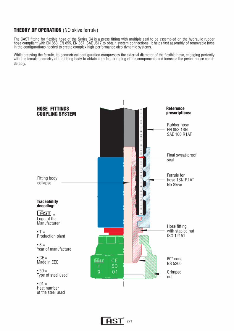
Fitting bodycollapse
Referenceprescriptions:
Rubber hoseEN 853 1SNSAE 100 R1AT
Final sweat-proofseal
Ferrule forhose 1SN-R1ATNo Skive
Hose fittingwith stapled nutISO 12151
60° coneBS 5200
Crimpednut
THEORY OF OPERATION (NO skive ferrule)
The CAST fitting for flexible hose of the Series C4 is a press fitting with multiple seal to be assembled on the hydraulic rubber hose compliant with EN 853, EN 855, EN 857, SAE J517 to obtain system connections. It helps fast assembly of removable hose in the configurations needed to create complex high-performance oleo-dynamic systems.
While pressing the ferrule, its geometrical configuration compresses the external diameter of the flexible hose, engaging perfectly with the female geometry of the fitting body to obtain a perfect crimping of the components and increase the performance consi-derably.
HOSE FITTINGSCOUPLING SYSTEM
Traceabilitydecoding:
= Logo of theManufacturer
• T =Production plant
• 3 =Year of manufacture
• CE =Made in EEC
• 50 =Type of steel used
• 01 =Heat numberof the steel used

272
TECHNICAL CHARACTERISTICS (NO skive ferrule)The CAST fitting for flexible hose of the Series C4 guarantees perfect tightness of the circuit regardless of the fluid used, provided that corrosive fluids are avoided and the nominal pressures and temperatures specified by the manufacturer are complied with. The male-female clinching system creates an innovative, state-of-the-art locking system that guarantees environmental protection and the safety of people and objects.
Normal vibrations do not alter the fitting’s performance, which, even at maximum values, retains its characteristics of absolute reliability. The rubber hoses to be assembled on the fittings must be strictly suitable for hydraulic applications, while it must be underlined that the hydraulic hoses with fittings have a limited life.
TECHNICAL INNOVATIONFor many years now there has been an increasing imperative market demand for fluid system components that guarantee three main factors:
SAFETy EASy ASSEMBLy LEAKAGE-FREE TIGHTNESS
These features, these days needed for the environmental and workplace safety (Leg. Decree 81/2008), as well as for product responsibility (Presidential Decree 224-EEC 85/374) and for the integrated ecological protection system have led us to develop this new series of products with the tube stop, adjustable geometry in the assembly phase, inter-locking clinching and increased sealing points in the rubber substrate and an additional sealing point to protect the seal just before the tube output from the sleeve.
Before pressing the sleeve on the rubber hose
After pressing the ferrule on the rubber hose
Sealing points 1-2-3-4
Pressure surfaces IIII 6-9Sealing points 5-7-8-10(on each single barb)
Pressure points: IIIIII 13Sealing points 11-12
Fitting body collapse
Multiple seal male-female crimping:Safety gUARANTEE - Protecting the ENVIRONMENT - Enhancing the PERFORMANCE

273
THEORY OF OPERATION (INTERLOCK)
The CAST fitting for flexible hose of the Series INTERLOCK is a press fitting with multiple seal to be assembled on the hydraulic rubber hose compliant with EN 856 to obtain system connections. It helps fast assembly of removable hoses in the configura-tions needed to create complex very high-performance hydraulic systems.
While pressing the ferrule, its geometrical configuration compresses the external metal reinforcement of the flexible tube, enga-ging perfectly with the female geometry of the fitting body to obtain a perfect coupling, which ensures the resistance to pressure peaks and serious stress, as part of the preset performance.
Fitting bodycollapse
Referenceprescriptions:
Rubber hoseEN 856
Ferrule4SH tubes
Hose fittingwith swivel nutISO 12151
60° coneBS 5200
Swivel nut
HOSE FITTINGSCOUPLING SYSTEM
Traceabilitydecoding:
= Logo of theManufacturer
• T =Production plant
• 3 =Year of manufacture
• CE =Made in EEC
• 50 =Type of steel used
• 01 =Heat numberof the steel used

274
TECHNICAL CHARACTERISTICS (INTERLOCK)
The CAST fitting for flexible hose of the Series INTERLOCK guarantees perfect tightness of the circuit regardless of the fluid used, provided that corrosive fluids are avoided and the nominal pressures and temperatures specified by the manufacturer are com-plied with.
INTERLOCK fittings are to only be used with spiral wired flexible tubes type: 4SP, 4SH and R13 according to standard EN 856. The assembly includes skiving the hose, both internally and externally, in a way to create two specific seal areas.
The particular interlock coupling ensures a perfect interlocking clinching between the sleeve, tube reinforcement and insert, by creating a solid metal to metal clinching. Please see fig. 1.
During the pressing phase, the internal profile of the sleeve compresses the external metal reinforcement of the tube to obtain a mechanical seal between the hose and the sleeve (please see fig. 1), and a hydraulic seal between the tube substrate and insert. Please see fig. 2.
Normal vibrations and pulses do not alter the fitting’s performance, which, even at maximum values, retains its characteristics of absolute reliability.
The rubber hoses to be assembled on the fittings must be strictly suitable for hydraulic applications, while it must be underlined that the hydraulic hoses with fittings have a limited life.
Before pressing the ferrule on the peeled hose
After pressing the ferrule on the peeled hose
Metal reinforcement
Hose substrate
Ferrule
Insert
Fitting body collapse

275
THEORY OF OPERATION (Quick connection)
The 80 quick connection .... is a new project of CAST S.p.A. aimed at reducing the time of assembly and disassembly of the flexi-ble hoses on the hydraulic systems, thus reducing the time and costs required to replace tools onboard the machine.
This quick release fitting provides: quick assembly and disassembly, no need for tools or utensils, since it is sufficient to manual-ly connect or disconnect the hose, simply acting on the mobile sleeve, which unlocks the sleeve release.
It eases and simplifies those maintenance interventions where, for dimension requirements, the hoses are mounted in battery or placed in areas inaccessible to iron roughnecks.
Fitting bodycollapse
Referenceprescriptions:
Rubber hoseEN 853 1SNSAE 100 R1AT
Ferrule fortube 1SN-R1AT
Unlocking hexagonal nut
Insertstraight
Connection body
Protection filter
Traceabilitydecoding:
= Logo of theManufacturer
• T =Production plant
• 3 =Year of manufacture
• CE =Made in EEC
• 50 =Type of steel used
• 01 =Heat numberof the steel used
QUICK CONNECTIONCOUPLING SYSTEM

276
TECHNICAL CHARACTERISTICS (Quick connection)
The series 80 quick connection .... is a quick release fitting for high performance hydraulic flexible hoses. It ensures a perfect seal of the circuit, regardless of the fluid used, provided that corrosive fluids are avoided and the nominal pressures and temperatures specified by the manufacturer are complied with.
Special care was paid to the safety parameters to be applied to the product. Right from the design phase, a filter was arranged inside the connection body with the task of stopping the entry of foreign bodies in the circuit downstream of the fitting. This pro-tects the set of valves, cylinders and actuators of the system from impurities, which would damage them.
MALE INSERT ASSEMBLY INSTRUCTIONS
1) Before the assembly, make sure that all the tools to be used are in perfect working order. It’s forbidden to use any non-con-form tool. Replace any inefficient tools.
2) Insert the male coupler in the connection body up to the stop. In this phase both green and red rings are not visible to the operator.
3) The check of the correct insertion must be performed on 100% of the connections by slightly pulling the male insert (Fig.2).
4) If you see only the green ring is the confirmation that the assembly has been performed correctly and pressure may be applied to the system. Should you see the red ring it means that the connection has not been properly assembled and is forbidden to let pressure in. In this case the assembly procedure must be performed until only the green ring is visible.
5) The disengagement cannot take not place casually, as this is prevented by the same pressure. The disengagement of the male connector may only take place by voluntarily pressing the unlocking sleeve (Fig. 3).
6) It’s forbidden to unlock the male insert from the connection body before having completely emptied the system from pressure.
ENgAgEMENT PHASE
DISENgAgEMENT PHASE

277
SAFETY FACTORS (Skive-No Skive-lnterlock-Quick connection)
• The press fittings for high pressure flexible tubes of the CAST S.p.A. Series C4 solve the problem of safety through the inter-locking clinching and automatic locking (obtained via a particular geometry of the sleeve and the fitting body). While making the fastening safer, we also set a precise mechanical limit for the crimping of the tube to give certainty of correct operation.
• The CAST production fully respects the construction parameters of the reference standards.
• The nominal working pressures (bar) given in the catalogue indicate the maximum permissible pressures (including pressure peaks). For higher pressure the items must be tested in accordance with the manufacturer for specific applications.
• It is imperative to thoroughly check the collapse of the fitting hole (insert) with the prescribed P-NP buffers. In case of curves, it is fundamental to obtain reference samples by cutting the fitting body at the base of the curve and carry out the check with the abovementioned buffers. Based on the samples obtained as so, it is possible to proceed to the serial crimping. Repeat this opera-tion periodically to ascertain the compliance with the parameters.
• The user must duly consider, for the purpose of a correct maintenance, that:
THE HOSES OF THE HYDRAULIC HOSES FITTED ARE PARTS WITH A LIMITED LIFE• The safety factor 4:1 is intended with static load and with the temperature at the indicated values and according to the pressures referred to in standards EN 853, EN 855, EN 856, EN 857, SAE J517, ISO 12151.
• The flexible hose must be necessarily fastened with a safety chain or protected by a guard to prevent striking the operator in case it becomes disengaged.
• It is understood that our reliable products are only guaranteed if the interconnection is made entirely with our products and components; please see traceability codes.
PRODUCT CONCEPT (Skive-No Skive-Quick connection) The most original aspect of the product is the male-female geometry with multiple seal. The new product goes one step beyond the known techniques and solves right from the start the problem of minor losses of tightness, leaks, sweating and safety of the crimping. The dimensional optimisation, innovative geometry and use of materials and treatments purposefully studied for the production of this series of products have allowed us to create an improved state-of-the-art product that is safe, respects the environment and ensures optimal performance.
HIGH SEALING (Skive-No Skive-Quick connection) The partition of the sealing surfaces lets us optimise the hose, sleeve and fitting coupling by creating the conditions to obtain a truly exceptional seal, from a crimping and seal point of view. The sealed points of the new product were tripled compared to the previous product, confirming the CONTINUOUS IMPROVEMENT of technology research and the development and innovation of our company, always committed to projects directed at future technology to protect the environment.
GENERAL INSTRUCTIONS (Skive-No Skive-lnterlock-Quick connection)Before starting the crimping of the sleeves to the hydraulic hose, check that the sleeves are of the dimensions suitable for the tube that you want to use, considering the pressures you intend to use, and check that the tube has not expired and has no defects. Check that the fitting body has no defects, and carefully insert it into the hole without damaging the inside of the hose, until the point of its natural stop, then proceed with the pressing by carefully observing the sleeve pressing diameters provided by the fitting manufacturer. It is imperative to thoroughly check the collapse of the fitting hole with the prescribed P-NP buffers to ensure the actual crimping between the hose, insert and sleeve. Before fastening the preassembled tube to the system onboard the machine, check the entire hose has no defects. If in doubt choose the most conservative and safest solution.
UTILISATION STANDARDS (Skive -No Skive -lnterlock -Quick connection)High quality tubes must be employed to assure correct use and related technical performance of the fitting. The use of hoses without the aforementioned characteristics may seriously impair the efficiency of the fitting, affecting its correct performance.
INTERCHANGEABILITY AND CODING (Skive-No Skive)The new CAST S.p.A. series of press fittings is perfectly interchangeable with the previous series 70 .... , also for individual com-ponents. The previous series 70 .... will be regularly supplied while stocks last and then automatically replaced by the new series 80 .... .

278
CHOICE OF FLEXIBLE HOSE SIZE
The graph below can be used for the correct choice of the flexible hose. It lets you calculate the tube dimension according to the flow value and speed of the fluid.
To find out the dimension of the right hose, draw a straight line connecting the known values of flow and speed. The intersection of this line on the middle of the picture determines the value of the diameter of the hose to be chosen. In case the value found does not correspond with one of the diameters DN indicated, the highest value must be chosen. Use the speeds suggested for intake and return pressure systems, to always have optimal working conditions.
E.g.:For a fluid flow Q=200 l/min and fluid speed V=3m/s, a size of DN38 is obtained.
VA
VR
VP
Legenda
Q = flexible hose flow in l/min
S = scross section of the flexible tube in cm2 (DN is the corresponding diameter)
V = fluid speed
VP = maximum speed suggested for pressured systems
VA = maximum speed suggested for intake systems
VR = maximum speed suggested for return systems
VA
VR
VP
5
1
1.5
3
2
4
30
20
15
6
8
10
20
30
40
50
7060
80
100
150
200
300
6
15
8
10
7
5
4
3
0.7
2
1.5
1
0.8
0.60.5
0.4
0.3
600
400
500
700
Q S
0.15
0.2
0.1
V
0.5
0.10.15
0.30.2
0.4
0.71
21.5
3
54
107
2015
3051
5
6
810
12
1619
25
3138
7
[l/min] DN [cm ] [m/sec]2
1.2
7.5

279
HOSE TYPE
HOSE DIMENSION 5 6 8 10 12 16 19 25 31 38 51 DN -3 -4 -5 -6 -8 -10 -12 -16 -20 -24 -32 SIZE 3/16 1/4 5/16 3/8 1/2 5/8 3/4 1 11/4 11/2 2 INCH
7301.. 250 225 215 180 160 130 105 88 63 50 40 bar EN 853 1SN SAE 100 R1AT 3625 3263 3118 2610 2320 1885 1523 1276 914 725 580 psi
7302.. 415 400 350 330 275 250 215 165 125 90 80 bar EN 853 2SN SAE 100 R2AT 6018 5800 5075 4785 3988 3625 3118 2393 1813 1305 1131 psi
7305.. - 225 215 180 160 - - - - - - bar EN 857 1SC - 3263 3118 2610 2320 - - - - - - psi
7306.. - 400 350 330 275 250 215 165 - - - bar EN 857 2SC SAE 100 R16 - 5800 5075 4785 3988 3625 3118 2393 - - - ps
7314..-7315.. - 250 250 250 - - - - - - - bar 1SC HYDRO-WASH - 3625 3625 3625 - - - - - - - psi
7316..-7317.. - 400 400 400 - - - - - - - bar 2SC HYDRO-WASH - 5800 5800 5800 - - - - - - - psi
7308.. - 450 - 445 415 350 350 280 - - - bar EN 856 4SP - 6525 - 6453 6018 5075 5075 4060 - - - psi
7309.. - - - - - - 420 380 325 290 250 bar EN 856 4SH - - - - - - 6090 5510 4713 4205 3625 psi
7310.. - - - - - - 345 345 345 345 345 bar EN 856 R13 - - - - - - 5000 5000 5000 5000 5000 psi
7311.. 210 200 190 175 - - - - - - - bar EN 855 R7 SAE 100 R7 3045 2900 2755 2537 - - - - - - - psi
7312.. 325 300 240 225 190 150 130 105 - - - bar R7TM 4710 4350 3480 3260 2755 2175 1885 1522 - - - psi
WORKING PRESSURES FOR FLExIBLE TUBES
BRAI
DED
SP
IRAL
WIR
EDTE
RMOP
LAST
IC
Notes: The outer diameters of the hoses stated are approximate. These diameters may vary based on the construction tolerances in accordance with the limits set by regulations.For applications with compressed air is the maximum pressure of 50 bar and the maximum temperature is 80°
HOSE BRANDINGManufacturer’s
logo
Hose typeas per
European standard
Hose typeas per USstandard
Nominalworkingpressure
Codehose
Hose dimensionas per European
standard
Hose dimensionas per USstandard
Date ofproduction
730105 EN 853 1SN SAE 100 R1ATDN12 MAX W.P. 160 BAR1/2’’ 1Q13
SYMBOL DESCRIPTION
Inner diameter of the flexible hose
DN= identification of the inner diameter of the hose according to the construction rules of the flexible tubes (EN)
mm= nominal inner diameter of the hose in mm according to the construction rules of the flexible tubes (EN/SAE)
SIZE= identification of the inner diameter of the hose according to SAE J517 (value expressed in 1/16 of an inch)
INCH= nominal inner diameter of the hose in inches
SYMBOL DESCRIPTION
Minimum bending radius
Maximum working pressure
Burst pressure
Hose unitary linear weight
Outer diameter of the flexible hose

280
Medium pressure hydraulic systems with mineral and vegetable oils, water, aqueous solutions, air*, inert gases*.
Substrate of synthetic oil resistant rubber.
1 braid of high resistance steel.
Black synthetic rubber resistant to abrasion, oils, fuels, ozone, atmospheric agents.* With gas pressures higher than 15 bars, the covering needs perforation.
from -40°C to +100°C, differences up to +120°C are tolerated.
HOSE EN 853 1SN - SAE 100 R1ATApplication
Manufacture:- Internal tube
- Reinforcement
- Covering
Workingtemperature
CODE
Ø internal Øexternal
Rmin.
PN P burst Weight g/mDN mm size inch bar psi bar psi
730101 5 4,8 -3 3/16 11,6 90 250 3625 1000 14500 180730102 6 6,6 -4 1/4 13 100 225 3263 900 13050 190730103 8 8,3 -5 5/16 14,7 115 215 3118 850 12325 220730104 10 9,9 -6 3/8 16,8 125 180 2610 720 10440 280730105 12 13 -8 1/2 20 180 160 2320 640 9280 360730106 16 16,4 -10 5/8 23,2 200 130 1885 520 7540 440730107 19 19,5 -12 3/4 27,1 240 105 1523 420 6090 560730108 25 26 -16 1 35,1 300 88 1276 350 5075 830730109 31 32,5 -20 11/4 42,5 420 63 914 250 3625 1070730110 38 38,7 -24 11/2 50,1 500 50 725 200 2900 1420730111 51 51,1 -32 2 64,1 630 40 580 160 2320 2010
Medium pressure hydraulic systems with mineral and vegetable oils, water, aqueous solutions, air*, inert gases*.
Substrate of synthetic oil resistant rubber.
2 braids of high resistance steel.
Black synthetic rubber resistant to abrasion, oils, fuels, ozone, atmospheric agents.* With gas pressures higher than 15 bars, the covering needs perforation.
from -40°C to +100°C, differences up to +120°C are tolerated.
HOSE EN 853 2SN - SAE 100 R2ATApplication
Manufacture:- Internal tube
- Reinforcement
- Covering
Workingtemperature
CODE
Ø internal Øexternal
Rmin.
PN P burst Weight g/mDN mm size inch bar psi bar psi
730201 5 4,8 -3 3/16 13,3 90 415 6018 1650 23925 300730202 6 6,6 -4 1/4 14,4 100 400 5800 1600 23200 310730203 8 8,3 -5 5/16 16 115 350 5075 1400 20300 370730204 10 9,9 -6 3/8 18,4 125 330 4785 1320 19140 440730205 12 13 -8 1/2 21,4 180 275 3988 1100 15950 530730206 16 16,4 -10 5/8 24,6 200 250 3625 1000 14500 660730207 19 19,5 -12 3/4 28,6 240 215 3118 850 12325 840730208 25 26 -16 1 37,1 300 165 2393 650 9425 1230730209 31 32,5 -20 11/4 46,7 420 125 1813 500 7250 1770730210 38 38,7 -24 11/2 54,5 500 90 1305 360 5220 2170730211 51 51,1 -32 2 66,7 630 80 1131 310 4500 2790
281
Medium pressure hydraulic systems with mineral and vegetable oils, water, aqueous solutions, air*, inert gases*.
Substrate of synthetic oil resistant rubber.
2 braids of high resistance steel.
Black synthetic rubber resistant to abrasion, oils, fuels, ozone, atmospheric agents.* With gas pressures higher than 15 bars, the covering needs perforation.
from -40°C to +100°C, differences up to +120°C are tolerated.
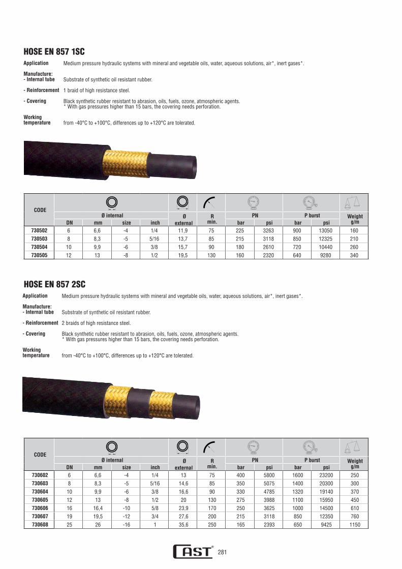
HOSE EN 857 2SCApplication
Manufacture:- Internal tube
- Reinforcement
- Covering
Workingtemperature
Medium pressure hydraulic systems with mineral and vegetable oils, water, aqueous solutions, air*, inert gases*.
Substrate of synthetic oil resistant rubber.
1 braid of high resistance steel.
Black synthetic rubber resistant to abrasion, oils, fuels, ozone, atmospheric agents.* With gas pressures higher than 15 bars, the covering needs perforation.
from -40°C to +100°C, differences up to +120°C are tolerated.
HOSE EN 857 1SCApplication
Manufacture:- Internal tube
- Reinforcement
- Covering
Workingtemperature
CODE
Ø internal Øexternal
Rmin.
PN P burst Weight g/mDN mm size inch bar psi bar psi
730502 6 6,6 -4 1/4 11,9 75 225 3263 900 13050 160730503 8 8,3 -5 5/16 13,7 85 215 3118 850 12325 210730504 10 9,9 -6 3/8 15,7 90 180 2610 720 10440 260730505 12 13 -8 1/2 19,5 130 160 2320 640 9280 340
CODE
Ø internal Øexternal
Rmin.
PN P burst Weight g/mDN mm size inch bar psi bar psi
730602 6 6,6 -4 1/4 13 75 400 5800 1600 23200 250730603 8 8,3 -5 5/16 14,6 85 350 5075 1400 20300 300730604 10 9,9 -6 3/8 16,6 90 330 4785 1320 19140 370730605 12 13 -8 1/2 20 130 275 3988 1100 15950 450730606 16 16,4 -10 5/8 23,9 170 250 3625 1000 14500 610730607 19 19,5 -12 3/4 27,6 200 215 3118 850 12350 760730608 25 26 -16 1 35,6 250 165 2393 650 9425 1150

282
For cleaning with high pressure hot water.
Special synthetic rubber resistant to 150°C, hot water, detergents.2 braids of high resistance steel.Special black synthetic rubber with cloth impression, microperforated, resistant to oils, abrasion and atmospheric agents.
from -40°C to +150°C
Application
Manufacture:- Internal tube- Reinforcement- Covering
Workingtemperature
For cleaning with high pressure hot water.
Special synthetic rubber resistant to 150°C, hot water, detergents.1 braid of high resistance steel.Special black synthetic rubber with cloth impression, microperforated, resistant to oils, abrasion and atmospheric agents.
from -40°C to +150°C
HOSE 1SC HIGH PRESSURE WATER JET WASHER Application
Manufacture:- Internal tube- Reinforcement- Covering
Workingtemperature
HOSE 2SC HIGH PRESSURE WATER JET WASHER
For cleaning with high pressure hot water.
Special synthetic rubber resistant to 150°C, hot water, detergents.1 braid of high resistance steel.Special black synthetic rubber with cloth impression, microperforated, resistant to oils, abrasion and atmospheric agents.
from -40°C to +150°C
HOSE 1SC HIGH PRESSURE WATER JET WASHER Application
Manufacture:- Internal tube- Reinforcement- Covering
Workingtemperature
CODE
Ø internal Øexternal
Rmin.
PN P burst Weight g/mDN mm size inch bar psi bar psi
731402 6 6,6 -4 1/4 11,8 75 250 3625 1000 14500 160731403 8 8,3 -5 5/16 13,7 85 250 3625 1000 14500 210731404 10 9,9 -6 3/8 15,5 90 250 3625 1000 14500 290
CODE
Ø internal Øexternal
Rmin.
PN P burst Weight g/mDN mm size inch bar psi bar psi
731602 6 6,6 -4 1/4 13 75 400 5800 1600 23200 250731603 8 8,3 -5 5/16 14,6 85 400 5800 1600 23200 300731604 10 9,9 -6 3/8 16,6 90 400 5800 1600 23200 370
CODE
Ø internal Øesterno
Rmin.
PN P burst Weight g/mDN mm size inch bar psi bar psi
731502 6 6,6 -4 1/4 11,8 75 250 3625 1000 14500 160731503 8 8,3 -5 5/16 13,7 85 250 3625 1000 14500 210731504 10 9,9 -6 3/8 15,5 90 250 3625 1000 14500 290

283
For cleaning with high pressure hot water.
Special synthetic rubber resistant to 150°C, hot water, detergents.
2 braids of high resistance steel.
Special black synthetic rubber with cloth impression, microperforated, resistant to oils, abrasion and atmospheric agents.
from -40°C to +150°C
Application
Manufacture:- Internal tube
- Reinforcement
- Covering
Workingtemperature
HOSE 2SC HIGH PRESSURE WATER JET WASHER
CODE
Ø internal Øexternal
Rmin.
PN P burst Weight g/mDN mm size inch bar psi bar psi
731702 6 6,6 -4 1/4 13 75 400 5800 1600 23200 250731703 8 8,3 -5 5/16 14,6 85 400 5800 1600 23200 300731704 10 9,9 -6 3/8 16,6 90 400 5800 1600 23200 370
Very high pressure hydraulic systems, also pulsating, with oils, water, aqueous solutions, air*, inert gases*.
Substrate of synthetic oil resistant rubber.
4 spirals of high resistance steel.
Black synthetic rubber resistant to abrasion, oils, fuels, ozone, atmospheric agents.* With gas pressures higher than 15 bars, the covering needs perforation.
from -40°C to +100°C, with discontinuous operation +120°C max.
HOSE EN 856 4SPApplication
Manufacture:- Internal tube
- Reinforcement
- Covering
Workingtemperature
CODE
Ø internal Øexternal
Rmin.
PN P burst Weight g/mDN mm size inch bar psi bar psi
730802 6 6,6 -4 1/4 17,6 150 450 6525 1800 26100 585730804 10 9,9 -6 3/8 21,1 180 445 6453 1780 25810 700730805 12 13 -8 1/2 24,2 230 415 6018 1660 24070 850730806 16 16,4 -10 5/8 27,9 250 350 5075 1400 20300 1040730807 19 19,5 -12 3/4 32 300 350 5075 1400 20300 1320730808 25 26 -16 1 38,9 340 280 4060 1120 16240 2060

284
Very high pressure hydraulic systems, also pulsating, with oils, water, aqueous solutions, air*, inert gases*.
Substrate of synthetic oil resistant rubber.
4 spirals of high resistance steel.
Black synthetic rubber resistant to abrasion, oils, fuels, ozone, atmospheric agents.* With gas pressures higher than 15 bars, the covering needs perforation.
from -40°C to +100°C, with discontinuous operation +120°C max.
HOSE EN 856 4SHApplication
Manufacture:- Internal tube
- Reinforcement
- Covering
Workingtemperature
CODE
Ø internal Øexternal
Rmin.
PN P burst Weight g/mDN mm size inch bar psi bar psi
730907 19 19,5 -12 3/4 31,9 280 420 6090 1680 24360 1430730908 25 26 -16 1 38,7 340 380 5510 1520 22040 2200730909 31 32,5 -20 11/4 45,2 460 325 4713 1300 18850 2580730910 38 38,7 -24 11/2 53,4 560 290 4205 1160 16820 3300730911 51 51,1 -32 2 67,3 700 250 3625 1000 14500 4940
Very high pressure hydraulic systems, also pulsating, with oils, water, aqueous solutions, air*, inert gases*.
Substrate of synthetic oil resistant rubber.
4 - 6 spirals of high resistance steel.
Black synthetic rubber resistant to abrasion, oils, fuels, ozone, atmospheric agents.* With gas pressures higher than 15 bars, the covering needs perforation.
from -40°C to +120°C.
HOSE EN 856 R13Application
Manufacture:- Internal tube
- Reinforcement
- Covering
Workingtemperature
CODE
Ø internal Øexternal
Rmin.
PN P burst Weight g/mDN mm size inch bar psi bar psi
731007 19 19,5 -12 3/4 32,3 240 345 5000 1380 20000 1570731008 25 26 -16 1 38,7 300 345 5000 1380 20000 1920731009 31 32,5 -20 11/4 49,8 420 345 5000 1380 20000 3600731010 38 38,7 -24 11/2 57,3 500 345 5000 1380 20000 4800731011 51 51,1 -32 2 71,1 630 345 5000 1380 20000 6600

285
Medium pressure hydraulic systems with mineral and vegetable oils, water, aqueous solutions, air*, inert gases*.
Oil resistant thermoplastic polymer.
2 braids of high resistance polyester.
abrasion resistant thermoplastic polyurethane.
from -40°C to +100°C.
HOSE ISO 3949 R7 EN 855 - SAE 100 R7Application
Manufacture:- Internal tube
- Reinforcement
- Covering
Workingtemperature
Medium pressure hydraulic systems with mineral and vegetable oils, water, aqueous solutions, air*, inert gases*.
Oil resistant thermoplastic polymer.
1 braid of high resistance steel.
abrasion resistant thermoplastic polyurethane.
from -40°C to +100°C.
Application
Manufacture:- Internal tube
- Reinforcement
- Covering
Workingtemperature
CODE
Ø internal Øexternal
Rmin.
PN P burst Weight g/mDN mm size inch bar psi bar psi
731101 5 4,8 -3 3/16 10 30 210 3045 840 12180 73731102 6 6,4 -4 1/4 11,8 35 200 2900 800 11600 90731103 8 8 -5 5/16 14,3 45 190 2755 760 11020 128731104 10 9,7 -6 3/8 16 55 175 2537 700 10150 155
CODE
Ø internal Øexternal
Rmin.
PN P burst Weight g/mDN mm size inch bar psi bar psi
731201 5 4,7 -3 3/16 10 30 325 4710 1300 18850 120
731202 6 6,3 -4 1/4 11,9 40 300 4350 1200 17400 170
731203 8 8,2 -5 5/16 14 50 240 3480 960 13920 221
731204 10 9,7 -6 3/8 16 60 225 3260 900 13050 260
731205 12 12,8 -8 1/2 19,2 75 190 2755 760 11020 326
731206 16 16 -10 5/8 23,3 110 150 2175 600 8700 412
731207 19 19,4 -12 3/4 25,5 150 130 1885 520 7540 454
731208 25 25 -16 1 32,5 185 105 1522 420 6090 590
HOSE R7TM

286
ASSEMBLY INSTRUCTIONS FOR FLEXIBLE HOSE FITTINGS
FITTINgS FOR FLEXIBLE HOSES WITHOUT EXTERNAL PEELINg - STANDARD SERIES1. Cut the hose at the desired length at a right angle with the specific disc cutter. Remove any cutting residues from the hose
edge (Fig.1).2. Insert the sleeve on the hose until it stops (Fig.3).3. Insert the stud of the fitting into the hose until the same fitting comes into contact with the sleeve (Fig.4).4. Press the sleeve on the hose with the suitable clamps following the directions in the pressing tables (Fig.5).5. It is imperative to check the collapse of the fitting hole with the appropriate tools. The assembled hoses that are not within the
set tolerance can not be used.
FITTINgS FOR FLEXIBLE HOSES WITH EXTERNAL PEELINg - STANDARD SERIES1. Cut the tube at the desired length at a right angle with the specific disc cutter. Remove any cutting residues from the hose
edge (Fig.1).2. Remove the external cover of the hose for the length indicated in the tables for the assembly to the outer diameter of the
metal reinforcement, avoiding damaging it (Fig.2).3. Insert the sleeve on the hose until it stops so to entirely cover the portion of the hose that has no external cover (Fig.3).4. Insert the hose holder stem of the fitting into the tube until the same fitting comes into contact with the sleeve (Fig.4).5. Press the sleeve on the hose with the suitable clamps following the directions in the pressing tables (Fig.5).6. It is imperative to check the collapse of the fitting hole with the appropriate tools. The assembled hoses that are not within the
set tolerance can not be used.
Fig. 1 Fig. 2 Fig. 3
Fig. 4 Fig. 5
Inside skiving lenght
Outside skiving lenght
FITTINgS FOR FLEXIBLE HOSES WITH EXTERNAL AND INTERNAL PEELINg - SERIES INTERLOCK 1. Cut the hose at the desired length at a right angle with the specific disc cutter. Remove any cutting residues from the hose
edge (Fig.6).2. Remove the external cover of the hose for the length indicated in the tables for the assembly to the outer diameter of the
metal reinforcement, avoiding damaging it (Fig.7).3. Remove the internal substrate of the hose for the length indicated in the tables for the assembly to the inner diameter of the
metal reinforcement, avoiding damaging it and eliminating any machining residue (Fig.8).4. Insert the sleeve on the hose until it stops so to entirely cover the portion of the hose that has no external cover (Fig.9).5. Insert the hose holder stem of the fitting into the tube until the same fitting comes into contact with the sleeve (Fig.10).6. Press the sleeve on the hose with the suitable clamps following the directions in the pressing tables (Fig.11).7. It is imperative to check the collapse of the fitting hole with the appropriate tools. The assembled hoses that are not within the
set tolerance can not be used and must remade.
Fig. 6 Fig. 7 Fig. 8
Fig. 9 Fig. 10 Fig. 11
Outside skiving lenght
287
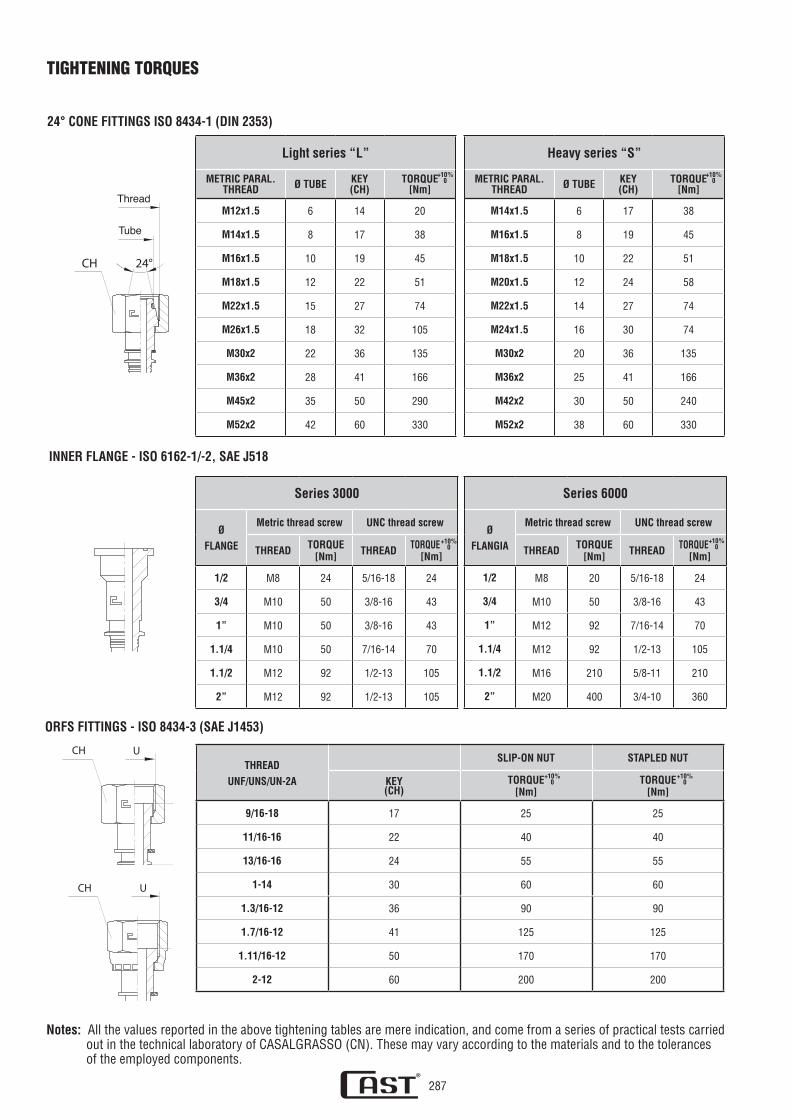
TIGHTENING TORQUES
Light series “L”
METRIC PARAL.THREAD Ø TUBE KEY
(CH)TORQUE
[Nm]
M12x1.5 6 14 20
M14x1.5 8 17 38
M16x1.5 10 19 45
M18x1.5 12 22 51
M22x1.5 15 27 74
M26x1.5 18 32 105
M30x2 22 36 135
M36x2 28 41 166
M45x2 35 50 290
M52x2 42 60 330
24° CONE FITTINgS ISO 8434-1 (DIN 2353)
INNER FLANgE - ISO 6162-1/-2, SAE J518
D1
L1
T
ORFS FITTINgS - ISO 8434-3 (SAE J1453)
24°CH
Tubo
Filetto
Heavy series “S”
METRIC PARAL.THREAD Ø TUBE KEY
(CH)TORQUE
[Nm]
M14x1.5 6 17 38
M16x1.5 8 19 45
M18x1.5 10 22 51
M20x1.5 12 24 58
M22x1.5 14 27 74
M24x1.5 16 30 74
M30x2 20 36 135
M36x2 25 41 166
M42x2 30 50 240
M52x2 38 60 330
Series 3000
Ø
FLANgE
Metric thread screw UNC thread screw
THREAD TORQUE[Nm] THREAD TORQUE
[Nm]
1/2 M8 24 5/16-18 24
3/4 M10 50 3/8-16 43
1” M10 50 3/8-16 43
1.1/4 M10 50 7/16-14 70
1.1/2 M12 92 1/2-13 105
2” M12 92 1/2-13 105
Series 6000
Ø
FLANgIA
Metric thread screw UNC thread screw
THREAD TORQUE[Nm] THREAD TORQUE
[Nm]
1/2 M8 20 5/16-18 24
3/4 M10 50 3/8-16 43
1” M12 92 7/16-14 70
1.1/4 M12 92 1/2-13 105
1.1/2 M16 210 5/8-11 210
2” M20 400 3/4-10 360
THREAD
UNF/UNS/UN-2A
SLIP-ON NUT STAPLED NUT
KEY(CH)
TORQUE[Nm]
TORQUE[Nm]
9/16-18 17 25 25
11/16-16 22 40 40
13/16-16 24 55 55
1-14 30 60 60
1.3/16-12 36 90 90
1.7/16-12 41 125 125
1.11/16-12 50 170 170
2-12 60 200 200
+10%0
+10%0
+10%0
+10%0
+10%0
+10%0
Notes: All the values reported in the above tightening tables are mere indication, and come from a series of practical tests carried out in the technical laboratory of CASALGRASSO (CN). These may vary according to the materials and to the tolerances of the employed components.
CH U
L1
T
CH U
L1
T
Thread
Tube

Thread Thread Thread
STAPLED NUT SWIVEL NUT SLIP-ON NUT
BSPPTHREAD
KEY(CH)
TORQUE[Nm]
TORQUE[Nm]
COPPIA[Nm]
g 1/8 14 15 25 20g1/4 19 20 65 30g 3/8 22 34 85 75g 1/2 27 60 150 130g 5/8 30 69 200 170g 3/4 32 115 260 220g 1” 41 140 320 270
g 1.1/4 50 - 500 420g 1.1/2 55 - 600 510
g 2” 70 - 700 600M 12x1,5 17 15 35 30M 14x1,5 19 20 45 38M 16x1,5 22 35 55 48M 18x1,5 24 48 70 60M 20x1,5 27 60 80 70M 22x1,5 27 60 100 85M 26x1,5 32 115 170 150M 30x1,5 36 130 250 210M 38x1,5 46 200 310 280M 45x1,5 55 290 380 320
+10%0
+10%0
+10%0
60°60° 60°
Thread Thread Thread
288
JIC 74° FITTINGS - ISO 8434-2 (SAE J514)
60° CONE FITTINGS ISO 8434-6 (BS 5200)
TIGHTENING TORQUES
STAPLED NUT SWIVEL NUT SLIP-ON NUT
THREADUNF/UN
KEY(CH)
TORQUE[Nm]
TORQUE[Nm]
TORQUE[Nm]
7/16-20 14 15 20 201/2-20 17 20 25 259/16-18 19 30 35 353/4-16 24 50 60 607/8-14 27 69 85 85
1.1/16-12 32 98 140 1401.3/16-12 36 118 - -1.5/16-12 41 140 230 2301.5/8-12 50 - 380 3801.7/8-12 60 - 460 460
+10%0
+10%0
+10%0
Notes: All the values reported in the above tightening tables are mere indication, and come from a series of practical tests carried out in the technical laboratory of CASALGRASSO (CN). These may vary according to the materials and to the tolerances of the employed components.

289
Rmin<Rmin
<Rmin
PRESCRIPTIONS FOR THE INSTALLATION OF FLEXIBLE HOSES ACCORDING TO DIN 20066To ensure the efficiency, safety and duration of the flexible hoses and related fittings it is necessary not to exceed the admitted working pressures and maximum temperatures, assemble the hoses correctly, use the most suitable fittings based on the assem-bly conditions, determine the length of the hoses in consideration of their movement, if any.
Therefore, the correct installation of the assembled flexible hoses requires the compliance with the prescriptions described below.
1. Do not apply torques to the flexible hoses along its axis as this could cause a drop in pressure (Fig.1).
2. The flexible hose must be assembled so that in normal working conditions it does not undergo any tensile stress other than that due to its own weight, and any compression stress to avoid breaking (Fig.2).
3. The flexible hose must be assembled by following the natural curvature as much as possible and maintaining the minimum bending radius allowed to prevent any constriction and collapse and not to shorten the life of the assembly. If this prescrip-tion can not be followed please use elbow fittings (Fig.3).
Fig. 1 Incorrect assembly Correct assembly
Fig. 2 Incorrect assembly Correct assembly
Fig. 3 Incorrect assembly Correct assembly
COMPRESSION TRACTION

290
PRESCRIPTIONS FOR THE INSTALLATION OF FLEXIBLE HOSES ACCORDING TO DIN 20066
4. If the flexible hose must be bent, its length must be such to maintain the minimum bending radius allowed and start the cur-ve only after a length equal to 1.5d. If this prescription can not be complied with, arrange for a protection in the folding area (Fig.4).
5. Use suitable fittings to avoid any undesired additional stress to the flexible hose (Fig.5).
6. 6. To prevent any damage to the flexible hose caused by external factors, it is necessary to eliminate any undesired mecha-nical action and prevent the flexible hose from rubbing against the components of the bearing structure or the other hoses. Select a suitable assembly position for the flexible hoses and adequate fixing. Protect the flexible hose with sheaths or similar protections, if necessary. The parts with sharp edges must be covered or eliminated (Fig.6).
Fig. 4 Incorrect assembly Correct assembly
Fig. 5 Incorrect assembly Correct assembly
Fig. 6 Incorrect assembly Correct assembly
CONTACT MINIMUM DISTANCE

291
PRESCRIPTIONS FOR THE INSTALLATION OF FLEXIBLE HOSES ACCORDING TO DIN 20066
7. For applications with moving parts, the length of the flexible hose must be calculated in a way that, within the range of motion, the minimum bending radius allowed is maintained and the hose does not undergo any tensile stress (Fig.7).
8. For applications with moving parts it is necessary to avoid the torque of the flexible hose when the longitudinal move-ment and the curvature take place in the same plain. This condition can be obtained through correct assembly, with sui-table constructive measurements and by using adequate fittings (Fig. 8).
Fig. 7 Incorrect assembly Correct assembly
Fig. 8 Incorrect assembly Correct assembly
CONTACT MINIMUM DISTANCE

292
LENGTH AND ORIENTATION OF THE ASSEMBLED FLEXIBLE HOSESThe length of a flexible hose assembled with straight male fittings must measured at the ends of the two connections. For female fittings the length is measured at the end of the conical seals or on the flat seal surfaces. In case of elbow fittings and eyelet fittin-gs the length is measured on the interaxes while also considering the criteria described for straight fittings (Fig.1). To determine the right length of an assembled hose it is advisable to consider the possible lengthening or shortening under pressure according to the construction rules for the individual hoses (from -2% to +4% for hoses type 1SN, 2SN, 2SC, 4SP, 4SH; ±3% for hose type R7).
When a flexible tube is assembled with one or both the elbow or eyelet fittings, their orientation needs to be indemnified for cor-rect assembly. Keeping the tube in horizontal position, the angle related to the fittings is determined starting from the fitting that is the closest to the eye of the observer in vertical position, downwards, and by rotating the furthest fitting anti clockwise (Fig.2).
Tolerances on the lengths and orientation of the flexible hoses assembled according to DIN 20066
Fig. 1 Fig. 2
HOSE LENgTHL
Ø INTERNAL HOSE TORQUEBFROM DN 5 TO DN 25 FROM DN 5 TO DN 25
Up to 630mm da -3 a +7mm da -4 a +12mm
±5°
Beyond 630 mm up to 1250 mm da -4 a +12mm da -6 a +20mm
Beyond 1250 mm up to 2500 mm da -6 a +20mm da -6 a +25mm
Beyond 2500 mm up to 8000 mm da -0,5% a +1,5%
Beyond 8000 mm da -1% a +3%