av20703 manual
TRANSCRIPT

SERVICE MANUAL
AV-20F703
COLOR TELEVISION
No. 52001May 2002
COPYRIGHT © 2002 VICTOR COMPANY OF JAPAN, LTD.
AV-20F703
PLAY
STOPREC
OPEN/CLOSE STILL/PAUSE
PAUSE
FFREW
– VCR CHANNEL +PREV NEXT
VCR/DVDPOWER TV/VCR
EXITMENU
ENTER
SLEEP TIMER
DISPLAY
BBE
INPUT
STANDARD
TV CATV POWER
C.C.
RM-C309G
AUDIO SELECT LIGHT
RETURN0
8
5
2
7
4
1
9
6
3
MUTING
CH
CH
VOL VOL
TV
VCR DVD
POWER
CONTENTSa SPECIFICATIONS ....................................................................................................................................2a OPERATING INSTRUCTIONS (APPENDIX)a SAFETY PRECAUTIONS ........................................................................................................................3a SPECIFIC SERVICE INSTRUCTIONS ....................................................................................................4a SERVICE ADJUSTMENTS ......................................................................................................................9a GUIDE FOR REPAIRING .......................................................................................................................14a STANDARD CIRCUIT DIAGRAM ........................................................................................................ 2-1a PARTS LIST ...........................................................................................................................................21

2 No. 52001
AV-20F703
SPECIFICATIONS
TELEVISIONPicture Tube: 20” (measured diagonally)
Color System: NTSC
TV RF System: CCIR (M)
Tuner Type: 181 Channel, Quartz PLL Frequency Synthesized
Receiving Channels: VHF 2-13
UHF 14-69
CATV 01-97 (5A)-(A-3)
98-99 (A-2)-(A-1)
14-22 (A)-(I)
23-36 (J)-(W)
37-65 (AA)-(FFF)
66-125 (GGG)-(125)
Intermediate Frequency: Picture (FP) : 45.75 MHz
Sound (FS) : 41.25 MHz
FP-FS : 4.50 MHz
Antenna Input: VHF/UHF In 75 ohms coaxial, F-Type Connector
Speaker: 2” x 4-3/4”, 8 ohms x 2
Audio Output Power: 2.5 W + 2.5 W
GENERALPower Source: 120 V AC, 60 Hz
Power Consumption: 105 Watts
Dimensions(W x H x D): 23-1/4” (590 mm) x 17-1/2” (444 mm) x 19-3/4” (498.5 mm)
Weight: 50.6 Ibs/23 kg
Video/Audio Inputs: Component input
Y input: 1.0 Vp-p, 75 ohm (RCA pin jack)
Pb, Pr input : 0.7 Vp-p, 75 ohm (RCA pin jack)
S-Video input
Y input: 1.0 Vp-p, 75 ohm
C input: 0.3 Vp-p, 75 ohm
Video input: 1.0 Vp-p, 75 ohm (RCA pin jack)
Audio input: -8dB, 47 kohm (RCA pin jack)
Headphone Jack: 3.5 mm mini-jack
Storage Temperature -20 °C ~ 60 °C
Operating Temperature 5 °C ~ 40 °C
Accessories:
Remote Control X 1
Batteries (UM-3) X 2
Design & specification are subject to change without notice.
AV-20F703
No. 52001 3
SERVICING NOTICES ON CHECKING
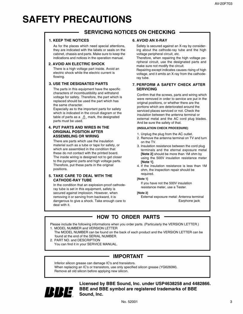
6. AVOID AN X-RAY1. KEEP THE NOTICESAs for the places which need special attentions,they are indicated with the labels or seals on thecabinet, chassis and parts. Make sure to keep theindications and notices in the operation manual.
3. USE THE DESIGNATED PARTS
5. TAKE CARE TO DEAL WITH THECATHODE-RAY TUBE
Safety is secured against an X-ray by consider-ing about the cathode-ray tube and the highvoltage peripheral circuit, etc.Therefore, when repairing the high voltage pe-ripheral circuit, use the designated parts andmake sure not modify the circuit.Repairing except indicates causes rising of highvoltage, and it emits an X-ray from the cathode-ray tube.
Please include the following informations when you order parts. (Particularly the VERSION LETTER.)1. MODEL NUMBER and VERSION LETTER
The MODEL NUMBER can be found on the back of each product and the VERSION LETTER can be found at the end of the SERIAL NUMBER.2. PART NO. and DESCRIPTION
You can find it in your SERVICE MANUAL.
HOW TO ORDER PARTS
Inferior silicon grease can damage IC's and transistors.When replacing an IC's or transistors, use only specified silicon grease (YG6260M).Remove all old silicon before applying new silicon.
IMPORTANT
2. AVOID AN ELECTRIC SHOCKThere is a high voltage part inside. Avoid anelectric shock while the electric current isflowing.
The parts in this equipment have the specificcharacters of incombustibility and withstandvoltage for safety. Therefore, the part which isreplaced should be used the part which hasthe same character.Especially as to the important parts for safetywhich is indicated in the circuit diagram or thetable of parts as a mark, the designatedparts must be used.
4. PUT PARTS AND WIRES IN THEORIGINAL POSITION AFTERASSEMBLING OR WIRINGThere are parts which use the insulationmaterial such as a tube or tape for safety, orwhich are assembled in the condition thatthese do not contact with the printed board.The inside wiring is designed not to get closerto the pyrogenic parts and high voltage parts.Therefore, put these parts in the originalpositions.
In the condition that an explosion-proof cathode-ray tube is set in this equipment, safety issecured against implosion. However, whenremoving it or serving from backward, it isdangerous to give a shock. Take enough care todeal with it.
PERFORM A SAFETY CHECK AFTERSERVICING
7.
Confirm that the screws, parts and wiring whichwere removed in order to service are put in theoriginal positions, or whether there are theportions which are deteriorated around theserviced places serviced or not. Check theinsulation between the antenna terminal orexternal metal and the AC cord plug blades.And be sure the safety of that.
(INSULATION CHECK PROCEDURE)
1.2.
3.
4.
Unplug the plug from the AC outlet.Remove the antenna terminal on TV and turnon the TV.Insulation resistance between the cord plugterminals and the eternal exposure metal[Note 2] should be more than 1M ohm byusing the 500V insulation resistance meter[Note 1].If the insulation resistance is less than 1Mohm, the inspection repair should berequired.
[Note 1]
If you have not the 500V insulationresistance meter, use a Tester.
[Note 2]External exposure metal: Antenna terminal
Earphone jack
Licensed by BBE Sound, Inc. under USP4638258 and 4482866.BBE and BBE symbol are registered trademarks of BBESound, Inc.
SAFETY PRECAUTIONS

4 No. 52001
AV-20F703
Rubber Cap
CRTSupport
GND on the CRT
Screwdriver
Alligator Clip
SupportCRT
GND on the CRT
1. REMOVAL OF ANODE CAPRead the following NOTED items before starting work.
After turning the power off there might still be a potentialvoltage that is very dangerous. When removing theAnode Cap, make sure to discharge the Anode Cap'spotential voltage.Do not use pliers to loosen or tighten the Anode Capterminal, this may cause the spring to be damaged.
*
*
REMOVAL
1. Follow the steps as follows to discharge the Anode Cap.(Refer to Fig. 1-1.)Connect one end of an Alligator Clip to the metal part of aflat-blade screwdriver and the other end to ground.While holding the plastic part of the insulated Screwdriver,touch the support of the Anode with the tip of theScrewdriver.A cracking noise will be heard as the voltage is discharged.
Flip up the sides of the Rubber Cap in the direction of thearrow and remove one side of the support.(Refer to Fig. 1-2.)
2.
Fig. 1-1
Fig. 1-2
3. After one side is removed, pull in the opposite direction toremove the other.
NOTE
DISASSEMBLY INSTRUCTIONS
INSTALLATION
1. Clean the spot where the cap was located with a smallamount of alcohol. (Refer to Fig. 1-3.)
NOTE
Confirm that there is no dirt, dust, etc. at the spot wherethe cap was located.
2.
3.
Arrange the wire of the Anode Cap and make sure thewire is not twisted.Turn over the Rubber Cap. (Refer to Fig. 1-4.)
Fig. 1-4
4. Insert one end of the Anode Support into the anodebutton, then the other as shown in Fig. 1-5.
CRTSupport
Fig. 1-5
5.6.
Confirm that the Support is securely connected.Put on the Rubber Cap without moving any parts.
Location of Anode Cap
Fig. 1-3
Take care not to damage the Rubber Cap.
SPECIFIC SERVICE INSTRUCTIONS
AV-20F703
No. 52001 5
DISASSEMBLY INSTRUCTIONS
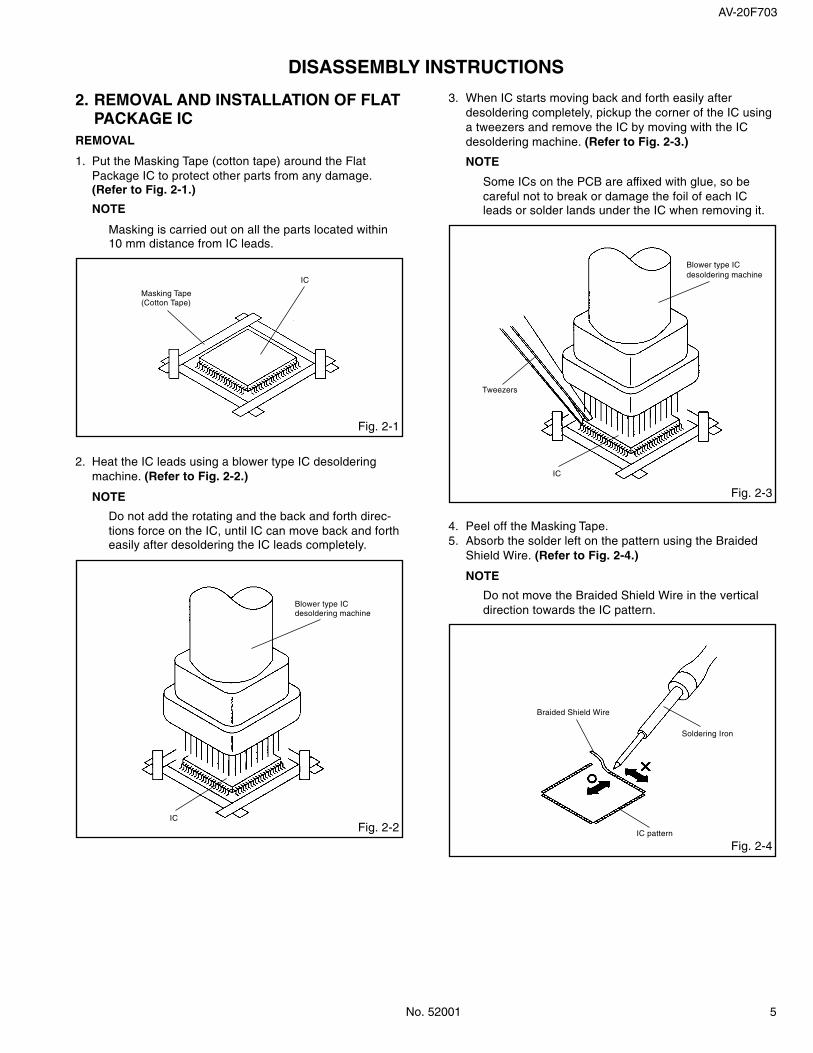
2. REMOVAL AND INSTALLATION OF FLATPACKAGE IC
REMOVAL
1. Put the Masking Tape (cotton tape) around the FlatPackage IC to protect other parts from any damage.(Refer to Fig. 2-1.)
NOTE
Masking is carried out on all the parts located within10 mm distance from IC leads.
Fig. 2-1
Masking Tape(Cotton Tape)
IC
2. Heat the IC leads using a blower type IC desolderingmachine. (Refer to Fig. 2-2.)
NOTE
Do not add the rotating and the back and forth direc-tions force on the IC, until IC can move back and fortheasily after desoldering the IC leads completely.
Fig. 2-2
Blower type ICdesoldering machine
IC
3. When IC starts moving back and forth easily afterdesoldering completely, pickup the corner of the IC usinga tweezers and remove the IC by moving with the ICdesoldering machine. (Refer to Fig. 2-3.)
NOTE
Some ICs on the PCB are affixed with glue, so becareful not to break or damage the foil of each ICleads or solder lands under the IC when removing it.
Fig. 2-3
Blower type ICdesoldering machine
Tweezers
IC
4.5.
Peel off the Masking Tape.Absorb the solder left on the pattern using the BraidedShield Wire. (Refer to Fig. 2-4.)
NOTE
Do not move the Braided Shield Wire in the verticaldirection towards the IC pattern.
Fig. 2-4
Braided Shield Wire
Soldering Iron
IC pattern

6 No. 52001
AV-20F703
DISASSEMBLY INSTRUCTIONS
Fig. 2-5
INSTALLATION
1. Take care of the polarity of new IC and then install thenew IC fitting on the printed circuit pattern. Then soldereach lead on the diagonal positions of IC temporarily.(Refer to Fig. 2-5.)
Soldering Iron
Solder temporarily Solder temporarily
2. Supply the solder from the upper position of IC leadssliding to the lower position of the IC leads. (Refer to Fig. 2-6.)
Fig. 2-6
Solder
IC
Soldering Iron
Supply solderingfrom upper positionto lower position
3. Absorb the solder left on the lead using the BraidedShield Wire. (Refer to Fig. 2-7.)
NOTE
Do not absorb the solder to excess.
Fig. 2-7
Soldering Iron
IC
Braided Shield Wire
4. When bridge-soldering between terminals and/or thesoldering amount are not enough, resolder using a Thin-tip Soldering Iron. (Refer to Fig. 2-8.)
Fig. 2-8
Thin-tip Soldering Iron
IC
5. Finally, confirm the soldering status on four sides of theIC using a magnifying glass.Confirm that no abnormality is found on the solderingposition and installation position of the parts around theIC. If some abnormality is found, correct by resoldering.
NOTE
When the IC leads are bent during soldering and/orrepairing, do not repair the bending of leads. If thebending of leads are repaired, the pattern may bedamaged. So, be always sure to replace the IC in thiscase.

AV-20F703
No. 52001 7
SERVICE MODE LIST
This unit provided with the following SERVICE MODES so you can repair, examine and adjust easily.To enter the Service Mode, press both set key and remote control key for more than 1 second.
Set Key Remocon Key Operations
VOL. (-) MIN 0 Releasing of V-CHIP PASSWORD.
VOL. (-) MIN 1
VOL. (-) MIN 3
VOL. (-) MIN 6
VOL. (-) MIN 8
VOL. (-) MIN 9
Initialization of the factory.NOTE: Do not use this for the normal servicing.
If you set a factory initialization, the memories are reset such as the channelsetting, and the POWER ON total hours.
POWER ON total hours is displayed on the screen.Refer to the “CONFIRMATION OF HOURS USED.
Can be checked of the INITIAL DATA of MEMORY IC.Refer to the “WHEN REPLACING EEPROM (MEMORY) IC”.
Writing of EEPROM initial data.NOTE: Do not use this for the normal servicing.
Display of the Adjustment MENU on the screen.Refer to the “ELECTRICAL ADJUSTMENT” (On-Screen Display Adjustment).
CONFIRMATION OF HOURS USEDPOWER ON total hours can be checked on the screen.Total hours are displayed in 16 system of notation.
NOTE: If you set a factory initialization, the total hours is reset to “0”.
1.2.
3.
Set the VOLUME to minimum.Press both VOL. DOWN button on the set and Channelbutton (6) on the remote control for more than 1 second.After the confirmation of using hours, turn off the power.
Initial setting content of MEMORY IC.
POWER ON total hours.= (16 x 16 x 16 x thousands digit value)+ (16 x 16 x hundreds digit value)+ (16 x tens digit value)+ (ones digit value)
INIT 00 A9
CRT ON 0010
Remocon format selection. (JVC format NEC format)NOTE: Supplied remocon can not be operated at NEC format. (The “N” is always displayed on the monitor.) Do not use this for the normal servicing.
8 No. 52001
AV-20F703
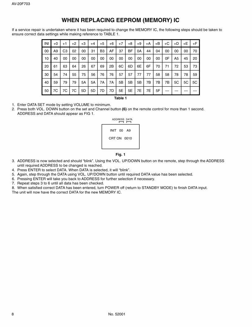
WHEN REPLACING EEPROM (MEMORY) IC
If a service repair is undertaken where it has been required to change the MEMORY IC, the following steps should be taken toensure correct data settings while making reference to TABLE 1.
3.
4.5.6.7.8.The unit will now have the correct DATA for the new MEMORY IC.
Table 1
ADDRESS is now selected and should “blink”. Using the VOL. UP/DOWN button on the remote, step through the ADDRESSuntil required ADDRESS to be changed is reached.Press ENTER to select DATA. When DATA is selected, it will “blink”.Again, step through the DATA using VOL. UP/DOWN button until required DATA value has been selected.Pressing ENTER will take you back to ADDRESS for further selection if necessary.Repeat steps 3 to 6 until all data has been checked.When satisfied correct DATA has been entered, turn POWER off (return to STANDBY MODE) to finish DATA input.
Fig. 1
1.2.
Enter DATA SET mode by setting VOLUME to minimum.Press both VOL. DOWN button on the set and Channel button (6) on the remote control for more than 1 second.ADDRESS and DATA should appear as FIG 1.
ADDRESS DATA
INIT 00 A9
CRT ON 0010
A9 C3 02 00 31 B3 AF 37 BF 0A
+0 +1 +2 +3 +4 +5 +6 +7 +8 +9 +A +B +C +D +E +FINI
40 00 00 00 00 00 00 00 0010 00 00 00 0F A5 45 20
00 44 04 00 00 00 70
61 64 26 67 69 2B 6C 6D 6E20 63 6F 70 71 72 53 73
54 55 75 56 76 76 57 57 7730 74 77 58 58 78 78 59
59 79 5A 5A 7A 7A 5B 5B 5B40 79 7B 7B 7B 5C 5C 5C
7C 7C 5D 5D 7D 7D 5E 5E 7E50 7C 7E 5F --- --- --- ---
AV-20F703
No. 52001 9
ELECTRICAL ADJUSTMENTS
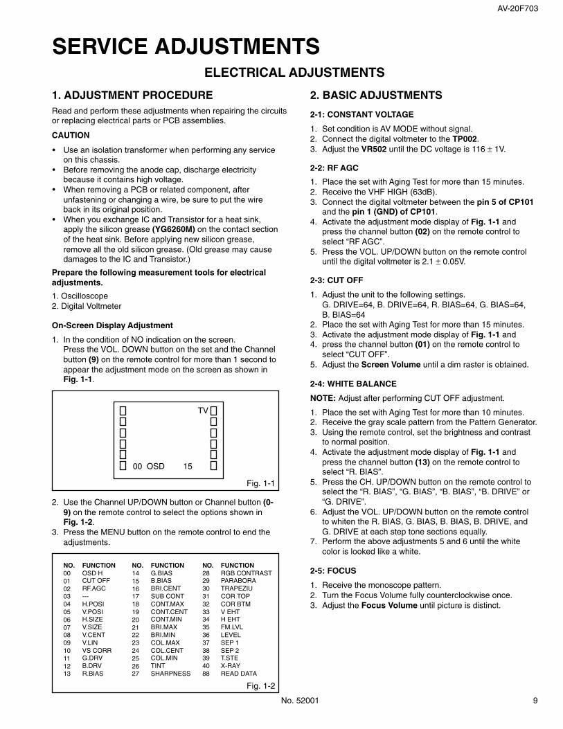
1. ADJUSTMENT PROCEDURERead and perform these adjustments when repairing the circuitsor replacing electrical parts or PCB assemblies.
CAUTION
•
•
•
•
Use an isolation transformer when performing any serviceon this chassis.Before removing the anode cap, discharge electricitybecause it contains high voltage.When removing a PCB or related component, afterunfastening or changing a wire, be sure to put the wireback in its original position.When you exchange IC and Transistor for a heat sink,apply the silicon grease (YG6260M) on the contact sectionof the heat sink. Before applying new silicon grease,remove all the old silicon grease. (Old grease may causedamages to the IC and Transistor.)
2. BASIC ADJUSTMENTS
Prepare the following measurement tools for electricaladjustments.
1. Oscilloscope2. Digital Voltmeter
On-Screen Display Adjustment
1. In the condition of NO indication on the screen.Press the VOL. DOWN button on the set and the Channelbutton (9) on the remote control for more than 1 second toappear the adjustment mode on the screen as shown inFig. 1-1.
Fig. 1-1
TV
00 OSD 15
2.
3.
Use the Channel UP/DOWN button or Channel button (0-9) on the remote control to select the options shown inFig. 1-2.Press the MENU button on the remote control to end theadjustments.
Fig. 1-2
NO.0001020304050607080910111213
FUNCTIONOSD HCUT OFFRF.AGC---H.POSIV.POSIH.SIZEV.SIZEV.CENTV.LINVS CORRG.DRVB.DRVR.BIAS
NO.2829303132333435363738394088
FUNCTIONRGB CONTRASTPARABORATRAPEZIUCOR TOPCOR BTMV EHTH EHTFM.LVLLEVELSEP 1SEP 2T.STEX-RAYREAD DATA
NO.1415161718192021222324252627
FUNCTIONG.BIASB.BIASBRI.CENTSUB CONTCONT.MAXCONT.CENTCONT.MINBRI.MAXBRI.MINCOL.MAXCOL.CENTCOL.MINTINTSHARPNESS
2-1: CONSTANT VOLTAGE
1.2.3.
Set condition is AV MODE without signal.Connect the digital voltmeter to the TP002.Adjust the VR502 until the DC voltage is 116 ± 1V.
2-2: RF AGC
1.2.3.
4.
5.
Place the set with Aging Test for more than 15 minutes.Receive the VHF HIGH (63dB).Connect the digital voltmeter between the pin 5 of CP101and the pin 1 (GND) of CP101.Activate the adjustment mode display of Fig. 1-1 andpress the channel button (02) on the remote control toselect “RF AGC”.Press the VOL. UP/DOWN button on the remote controluntil the digital voltmeter is 2.1 ± 0.05V.
2-3: CUT OFF
1.
2.3.4.
5.
Adjust the unit to the following settings.G. DRIVE=64, B. DRIVE=64, R. BIAS=64, G. BIAS=64,B. BIAS=64Place the set with Aging Test for more than 15 minutes.Activate the adjustment mode display of Fig. 1-1 andpress the channel button (01) on the remote control toselect “CUT OFF”.Adjust the Screen Volume until a dim raster is obtained.
2-5: FOCUS
1.2.3.
Receive the monoscope pattern.Turn the Focus Volume fully counterclockwise once.Adjust the Focus Volume until picture is distinct.
2-4: WHITE BALANCE
NOTE: Adjust after performing CUT OFF adjustment.
1.2.3.
4.
5.
6.
7.
Place the set with Aging Test for more than 10 minutes.Receive the gray scale pattern from the Pattern Generator.Using the remote control, set the brightness and contrastto normal position.Activate the adjustment mode display of Fig. 1-1 andpress the channel button (13) on the remote control toselect “R. BIAS”.Press the CH. UP/DOWN button on the remote control toselect the “R. BIAS”, “G. BIAS”, “B. BIAS”, “B. DRIVE” or“G. DRIVE”.Adjust the VOL. UP/DOWN button on the remote controlto whiten the R. BIAS, G. BIAS, B. BIAS, B. DRIVE, andG. DRIVE at each step tone sections equally.Perform the above adjustments 5 and 6 until the whitecolor is looked like a white.
SERVICE ADJUSTMENTS

10 No. 52001
AV-20F703
ELECTRICAL ADJUSTMENTS
2-6: HORIZONTAL POSITION
1.2.
3.
4.
Receive the monoscope pattern.Using the remote control, set the brightness and contrastto normal position.Activate the adjustment mode display of Fig. 1-1 andpress the channel button (04) on the remote control toselect “H. POSI”.Press the VOL. UP/DOWN button on the remote controluntil the SHIFT quantity of the OVER SCAN on right andleft becomes minimum.
2-8: VERTICAL SIZE
1.2.
3.
4.
Receive the monoscope pattern.Using the remote control, set the brightness and contrastto normal position.Activate the adjustment mode display of Fig. 1-1 andpress the channel button (07) on the remote control toselect “V. SIZE”.Press the VOL. UP/DOWN button on the remote controluntil the SHIFT quantity of the OVER SCAN on upside anddownside becomes 9 ± 2%.
2-7: VERTICAL POSITION
1.2.
3.
4.
Receive the monoscope pattern.Using the remote control, set the brightness and contrastto normal position.Activate the adjustment mode display of Fig. 1-1 andpress the channel button (05) on the remote control toselect “V. POSI”.Press the VOL. UP/DOWN button on the remote controluntil the horizontal line becomes fit to the notch of theshadow mask.
2-11: SUB BRIGHTNESS
1.
2.
3.4.
5.
Activate the adjustment mode display of Fig. 1-1 andpress the channel button (16) on the remote control toselect “BRI. CENT”.Press the VOL. UP/DOWN button on the remote controluntil the brightness step No. becomes “50”.Receive a broadcast and check if the picture is normal.Press the INPUT button on the remote control to set to theAV mode. Then perform the above adjustments 1~3.Press the INPUT button on the remote control to set to theCS mode. Then perform the above adjustments 1~3.
2-9: VERTICAL LINEARITY
NOTE: Adjust after performing adjustments in section 2-8.After the adjustment of Vertical Linearity, reconfirmthe Vertical Position and Vertical Size adjustments.
Receive the monoscope pattern.Using the remote control, set the brightness and contrastto normal position.Activate the adjustment mode display of Fig. 1-1 andpress the channel button (09) on the remote control toselect “V. LIN”.Press the VOL. UP/DOWN button on the remote controluntil the SHIFT quantity of the OVER SCAN on upside anddownside becomes minimum.
1.2.
3.
4.
2-12: TINT/COLOR CENT
1.2.3.
4.
5.
6.7.
8.
9.
10.11.
12.
13.
14
15.
16.
17.
Fig. 2-1
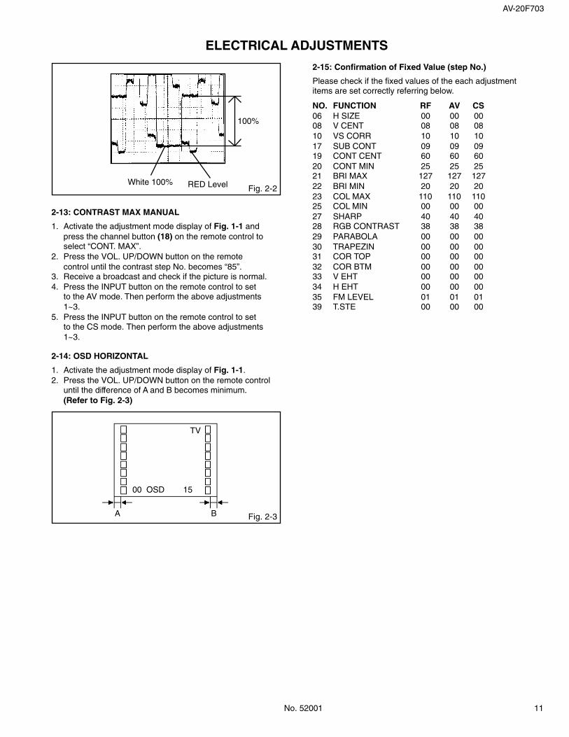
Receive the color bar pattern. (RF Input)Connect the oscilloscope to TP806.Using the remote control, set the brightness, contrast,color and tint to normal position.Activate the adjustment mode display of Fig. 1-1 andpress the channel button (26) on the remote control toselect “TINT”.Press the VOL. UP/DOWN button on the remote controluntil the section “A” becomes a straight line(Refer to Fig. 2-1).Connect the oscilloscope to TP804.Press the channel button (24) on the remote control toselect “COL. CENT”.Adjust the VOLTS RANGE VARIABLE knob of theoscilloscope until the range between white 100% and0% is set to 4.4 scales on the screen of the oscilloscope.Press the VOL. UP/DOWN button on the remote controluntil the red color level is adjusted to 115 ± 10% of thewhite level. (Refer to Fig. 2-2)Receive the color bar pattern. (Audio Video Input)Press the INPUT button on the remote control to setto the AV mode. Then perform the above adjustments2~9.Press the INPUT button on the remote control to set tothe CS mode.Activate the adjustment mode display of Fig. 1-1 andpress the channel button (26) on the remote control toselect “TINT”.Press the VOL. UP/DOWN button on the remote controluntil the tint step No. becomes “50”.Press the channel button (24) on the remote control toselect “COL. CENT”.Press the VOL. UP/DOWN button on the remote controluntil the color step No. becomes “62”.Receive a broadcast and check if the picture is normal.
“A”
2-10: LEVEL
1.2.
3.
4.
Receive the monoscope pattern (70dB).Connect the AC voltmeter to pin 6 of CP101 and the pin 1(GND) of CP101.Activate the adjustment mode display of Fig. 1-1 andpress the channel button (36) on the remote control toselect “LEVEL”.Press the VOL. UP/DOWN button on the remote controluntil the AC voltmeter is 75 ± 2mV.
AV-20F703
No. 52001 11
ELECTRICAL ADJUSTMENTS
2-13: CONTRAST MAX MANUAL
1.
2.
3.4.
5.
Activate the adjustment mode display of Fig. 1-1 andpress the channel button (18) on the remote control toselect “CONT. MAX”.Press the VOL. UP/DOWN button on the remotecontrol until the contrast step No. becomes “85”.Receive a broadcast and check if the picture is normal.Press the INPUT button on the remote control to setto the AV mode. Then perform the above adjustments1~3.Press the INPUT button on the remote control to setto the CS mode. Then perform the above adjustments1~3.
Fig. 2-2White 100% RED Level
100%
2-14: OSD HORIZONTAL
1.2.
Activate the adjustment mode display of Fig. 1-1.Press the VOL. UP/DOWN button on the remote controluntil the difference of A and B becomes minimum.(Refer to Fig. 2-3)
Fig. 2-3
TV
00 OSD 15
A B
2-15: Confirmation of Fixed Value (step No.)
Please check if the fixed values of the each adjustmentitems are set correctly referring below.
NO.0608101719202122232527282930313233343539
FUNCTIONH SIZEV CENTVS CORRSUB CONTCONT CENTCONT MINBRI MAXBRI MINCOL MAXCOL MINSHARPRGB CONTRASTPARABOLATRAPEZINCOR TOPCOR BTMV EHTH EHTFM LEVELT.STE
RF000810096025127201100040380000000000000100
AV000810096025127201100040380000000000000100
CS000810096025127201100040380000000000000100
12 No. 52001
AV-20F703
ELECTRICAL ADJUSTMENTS
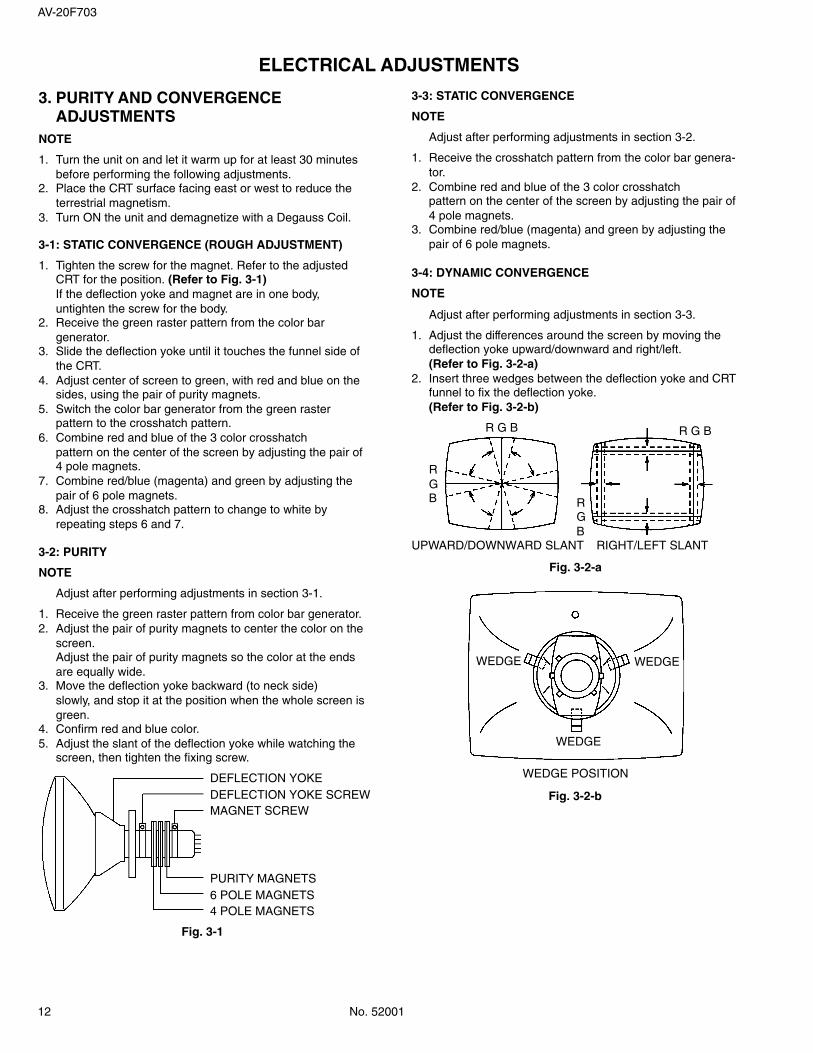
3. PURITY AND CONVERGENCEADJUSTMENTS
NOTE
1.
2.
3.
Turn the unit on and let it warm up for at least 30 minutesbefore performing the following adjustments.Place the CRT surface facing east or west to reduce theterrestrial magnetism.Turn ON the unit and demagnetize with a Degauss Coil.
3-1: STATIC CONVERGENCE (ROUGH ADJUSTMENT)
1.
2.
3.
4.
5.
6.
7.
8.
Tighten the screw for the magnet. Refer to the adjustedCRT for the position. (Refer to Fig. 3-1)If the deflection yoke and magnet are in one body,untighten the screw for the body.Receive the green raster pattern from the color bargenerator.Slide the deflection yoke until it touches the funnel side ofthe CRT.Adjust center of screen to green, with red and blue on thesides, using the pair of purity magnets.Switch the color bar generator from the green rasterpattern to the crosshatch pattern.Combine red and blue of the 3 color crosshatchpattern on the center of the screen by adjusting the pair of4 pole magnets.Combine red/blue (magenta) and green by adjusting thepair of 6 pole magnets.Adjust the crosshatch pattern to change to white byrepeating steps 6 and 7.
3-2: PURITY
NOTE
Adjust after performing adjustments in section 3-1.
1.2.
3.
4.5.
Receive the green raster pattern from color bar generator.Adjust the pair of purity magnets to center the color on thescreen.Adjust the pair of purity magnets so the color at the endsare equally wide.Move the deflection yoke backward (to neck side)slowly, and stop it at the position when the whole screen isgreen.Confirm red and blue color.Adjust the slant of the deflection yoke while watching thescreen, then tighten the fixing screw.
DEFLECTION YOKEDEFLECTION YOKE SCREWMAGNET SCREW
PURITY MAGNETS6 POLE MAGNETS4 POLE MAGNETS
Fig. 3-1
3-3: STATIC CONVERGENCE
NOTE
Adjust after performing adjustments in section 3-2.
1.
2.
3.
Receive the crosshatch pattern from the color bar genera-tor.Combine red and blue of the 3 color crosshatchpattern on the center of the screen by adjusting the pair of4 pole magnets.Combine red/blue (magenta) and green by adjusting thepair of 6 pole magnets.
3-4: DYNAMIC CONVERGENCE
NOTE
Adjust after performing adjustments in section 3-3.
1.
2.
Adjust the differences around the screen by moving thedeflection yoke upward/downward and right/left.(Refer to Fig. 3-2-a)Insert three wedges between the deflection yoke and CRTfunnel to fix the deflection yoke.(Refer to Fig. 3-2-b)
R G B
RGB R
GB
R G B
UPWARD/DOWNWARD SLANT RIGHT/LEFT SLANT
Fig. 3-2-a
WEDGE WEDGE
WEDGE
WEDGE POSITION
Fig. 3-2-b

AV-20F703
No. 52001 13
ELECTRICAL ADJUSTMENTS
4. ELECTRICAL ADJUSTMENT PARTS LOCATION GUIDE (WIRING CONNECTION)
CP803
CP804
TP
806
TP
804
R808
R804
CP
852
CP801_1CP851_1
J801
CP401
CP851A
TP002
CP801A
T501
VR502
TU
001
J702
J701
J703
J708
CP1001
W169
R527
CP101
J704
FB401
AC IN
CD801
CD
851
CP852B
CD803
CRT
CRT
SPEAKER
CD
1001
L503 CP502
CRT
VM COIL PCBCRT PCB
MAIN PCB
CD
852

14 No. 52001
AV-20F703
IC DESCRIPTION
NO. Pin name Symbol I/O Logic OptionFunction1 P11/SCL1 AUDIO MUTE O 0 Audio MUTE Output C-MOS2 P00/PM0 EXT MUTE O 1 Audio MUTE Output for external Output3 P01/PWM1 STANDBY_H O 1 Output HIGH at a teleevision power off. Nch-OD
Nch-OD
4 P02/PWM2 BBE-H O BBE Control Output Nch-OD5 P03/PWM3/AD1 AFT I Voltage of tuning input Nch-OD6 P04/PWM4/AD2 KEY1 I Main unit key input Nch-OD7 P05/AD3 KEY2 I Main unit key input Nch-OD8 P06/INT2/AD4 X-RAY I Input terminal of X-RAY detection. Nch-OD9 P07/INT1 REMOCON I Remote control input Nch-OD
10 P20/SCLK/AD5 ONTIMER LED O ON-TIMER LED control output. C-MOS11 P21/AOUT/AD6 O C-MOS12 P22/SIN/AD7 AV2 O External SW output2 C-MOS13 P23/TIM3 AV1 O External SW output1 C-MOS14 P24/TIM2 O C-MOS15 P25/INT3 POWER FAIL I 0 Power failure detector input C-MOS16 P26/XCIN DEGAUSS_H O 1 Degauss output C-MOS17 P27/XCOUT X-RAY_TEST O 1 X-RAY detector input C-MOS18 CNVSS CNVSS GND19 XIN Xin I Main Oscillation20 XOUT Xout O Main Oscillation21 VSS VSS GND22 VCC VCC 5V23 FILT FILT24 HLF HLF O Filter of slicer25 VHOLD V.HOLD I Condenser of slicer26 CVIN CVIN I Video signal input27 RESET RESET I 0 Reset signal input28 FSCIN (FSCIN) I (Main Clock Occurrence circuit input)29 PONCONT/P15 POWER O 1 Power control output. C-MOS30 P31/SCL3 SCL1 O Serial clock output (IIC BUS) C-MOS31 P30/SDA3 SDA1 I/O Serial data input/output C-MOS32 CLKCONT/P10 (CLOCK CONT) O (Main Clock Request output) C-MOS33 P55/OUT BRANK O 1 BLANK Output for OSD/CCD C-MOS34 P54/R RED R O 1 Red output of RGB image output C-MOS35 P53/G GREEN G O 1 Green output of RGB image output C-MOS36 P52/B BLUE B O 1 Blue output of RGB image output C-MOS37 P51/VSYNC V.SYNC I 0 Vertical synchronization input38 P50/HSYNC H.SYNC I 0 Horizontal synchronization input39 P16/AD8/TIM2 SYNC I Input terminal for H-SYNC. C-MOS40 P14/SDA2 IIC_OFF I 0 Serial clock/data stop input C-MOS41 P13/SDA1 PROTECT O 1 Output HIGH at turning off a television. C-MOS42 P12/SCL2 H_CTL O 1 Output HIGH at turning off a television. C-MOS
S
MAIN PCB OEC7075A (IC101)
GUIDE FOR REPAIRING

AV-20F703
No. 52001 15
TROUBLESHOOTING GUIDE
NO POWER
YesIs the voltage at the point (A)in the Figure DC160V ?
Is the voltage at pin Gof Q502 DC5V ?
Yes
No
Check R501 and R541.
Check the rectifying circuit.
Yes
No
Yes
No
Is the voltage at the point (B)in the Figure DC164V ?
Is the voltage at the point (C)in the Figure AC120V ?
Yes
No
Broken wire of L501.
Is the voltage on bothends of S501 AC120V ?
Broken wire of F501.Yes
No
Broken wire of AC cord or checkS501.
Is the voltage at the point (E)in the Figure AC120V ?
Check Q502 and associated circuit.
Check Q514 and associated circuit.
No
T502
5 8A
D
S
G
3
Q514
Q502
IC504
R501
B
D501~D504
L501
C
E
F501
S501
CD501

16 No. 52001
AV-20F703
TROUBLESHOOTING GUIDE
Is the heater voltage atpin 10 of J802 AC6.2V ?
Is the high voltage ofANODE 27KV~28KV ?
No
NO RASTER
Does the RASTERappear at maximumBRIGHT/CONTRAST ?
Yes
No
Is the voltage of pin 1 ofCP801 DC180V ?
Yes
No
Check the output circuit andassociated circuit.
Check the 180V line.
Yes Yes
No
Contact defects of CRT or CRTSocket.
Check the HEATER circuit.
Yes
No
Is collector voltagesof Q405 DC114V andQ402 DC27V ?
Check FB401 and associated circuit.
No
YesIs the waveform at baseof Q402 normal ?
No
YesIs the waveform at pin34 of IC601 normal ?
Check the circuit from pin 34 ofIC601 to Q402.
Check IC601 and associated circuit.
Check Q402 and check peripheralcircuit.
AV-20F703
No. 52001 17
TROUBLESHOOTING GUIDE
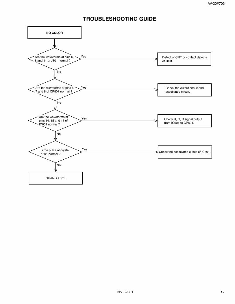
NO COLOR
Are the waveforms at pins 6,8 and 11 of J801 normal ?
Yes
No
Defect of CRT or contact defectsof J801.
Are the waveforms at pins 6,7 and 8 of CP801 normal ?
Yes
No
Check the output circuit andassociated circuit.
Are the waveforms atpins 14, 15 and 16 ofIC601 normal ?
Yes
No
Check R, G, B signal outputfrom IC601 to CP801.
Is the pulse of crystalX601 normal ?
No
Yes
CHANG X601.
Check the associated circuit of IC601.
18 No. 52001
AV-20F703
TROUBLESHOOTING GUIDE
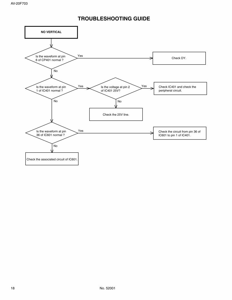
NO VERTICAL
Is the waveform at pin6 of CP401 normal ?
Yes
No
Check DY.
Is the waveform at pin1 of IC401 normal ?
No
Yes Is the voltage at pin 2of IC401 25V?
Yes
No
Check IC401 and check theperipheral circuit.
Check the 25V line.
Is the waveform at pin36 of IC601 normal ?
No
Yes
Check the associated circuit of IC601.
Check the circuit from pin 36 ofIC601 to pin 1 of IC401.
AV-20F703
No. 52001 19
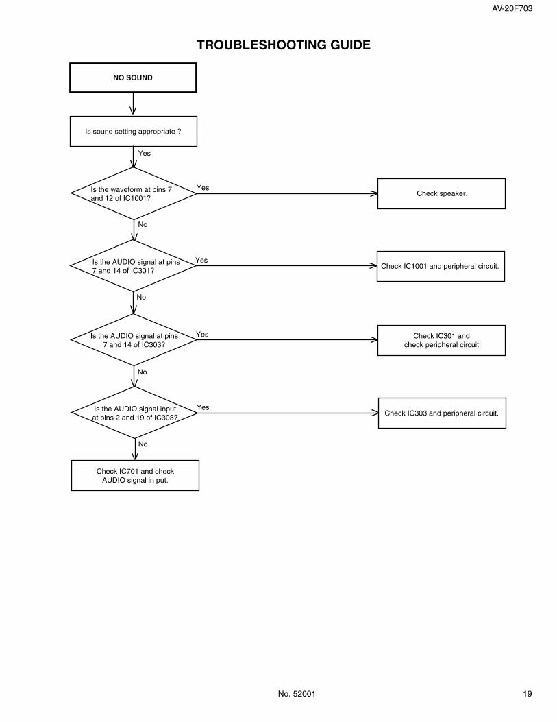
TROUBLESHOOTING GUIDE
NO SOUND
Yes
Is sound setting appropriate ?
Is the waveform at pins 7and 12 of IC1001?
Yes
No
Check speaker.
Is the AUDIO signal at pins7 and 14 of IC301?
Yes
No
Check IC1001 and peripheral circuit.
Check IC701 and checkAUDIO signal in put.
Is the AUDIO signal inputat pins 2 and 19 of IC303?
Yes
No
Check IC303 and peripheral circuit.
Is the AUDIO signal at pins7 and 14 of IC303?
Yes Check IC301 and check peripheral circuit.
No

20 No. 52001
AV-20F703
TROUBLESHOOTING GUIDE
NO CCD
Is the video signal at pin26 of IC101 ?
Is the video signal atpin 31 of IC701 ?
No
Yes Check IC701 and checkperipheral circuit.
Check IC601 and check
paripheral circuit.
Yes Check IC1001 and checkperipheral circuit.
No

Printed in JapanVP0205SW
JVC SERVICE & ENGINEERING COMPANY OF AMERICA
Head office : 1700 Valley Road, Wayne, New Jersey 07470 (973)317-5000East Coast : 10 New Maple Avenue, Pine Brook, New Jersey 07058 (973)396-1000Midwest : 705 Enterprise St. Aurora, Illinois 60504 (630)851-7855West Coast : 5665 Corporate Avenue, Cypress, California 90630 (714)229-8011Southwest : 10700 Hammerly, Suite 105, Houston, Texas 77043 (713)935-9331Hawaii : 2969 Mapunapuna Place, Honolulu, Hawaii 96819 (808)833-5828Southeast : 1500 Lakes Parkway, Lawrenceville, Georgia 30243 (770)339-2582
JVC CANADA INC.Head office : 21 Finchdene Square Scarborough, Ontario M1X 1A7 (416)293-1311Vancouver : 13040 Worster Court Richmond B.C. V6V 2B3 (604)270-1311
DIVISION OF JVC AMERICAS CORP.
®