autotrack manual - doppler systems radio direction … pdfs/autotrack manual.pdfenter calibration...
TRANSCRIPT

USER'S GUIDE
AUTOTRACK MANUAL
Copyright © 2007 Doppler Systems LLC. All rights reserved
The software contains proprietary information of Doppler Systems LLC.; it is provided under a license agreement containing restrictions on use and disclosure and is also protected by copyright law. Reverse engineering of the software is prohibited.
Due to continued product development this information may change without notice. The information and intellectual property contained herein is confidential between Doppler Systems LLC. and the client and remains the exclusive property of Doppler Systems LLC. If you find any problems in the documentation, please report them to us in writing. Doppler Systems LLC does not warrant that this document is error-free.
AuthorIT™ is a trademark of AuthorIT Software Corporation Ltd.
Microsoft Word, Microsoft Office, Windows®, Window 2000™, Window XP™, Windows Vista™ are trademarks of the Microsoft Corporation.
This document was created using AuthorIT™, Total Document Creation (see AuthorIT Home - http://www.author-it.com).
Doppler Systems LLC PO Box 2780
Carefree, Arizona 85377 USA
+01 (480) 488-9755 E-Mail: [email protected]
Website: http://www.dopsys.com

CONTENTS
INTRODUCTION .................................................................................................................................... 3 Typographical Conventions............................................................................................................... 3 Using this Manual.............................................................................................................................. 4 Computer Requirements .................................................................................................................. 4 Overview of the Programs................................................................................................................. 4
INSTALLATION...................................................................................................................................... 5
CREATING MAPS.................................................................................................................................. 7 Creating a Map Image....................................................................................................................... 9
Graphics File Formats.................................................................................................................. 9 Scanning in an Image .................................................................................................................. 9 Using Google Earth.....................................................................................................................10 Using Microsoft MapPoint .........................................................................................................10
Using MapFix ...................................................................................................................................11 Importing the Image...................................................................................................................11 Enter Calibration Points .............................................................................................................11 Saving the Map File....................................................................................................................12
USING AUTOTRACK............................................................................................................................13 Setting Up AutoTrack.......................................................................................................................15
Setting Up the Hardware ...........................................................................................................15 Setting the Receiver Address ....................................................................................................16 Displaying Maps .........................................................................................................................17 Entering Auto Tune Channels....................................................................................................20 Setting the COM Port .................................................................................................................21 Calibrating the Compass ...........................................................................................................21 Setting up the GPS.....................................................................................................................21
Running AutoTrack..........................................................................................................................23 Capturing a Line-of-Bearing.......................................................................................................24 Deleting a Line-of-Bearing .........................................................................................................24 Deleting All Sites ........................................................................................................................24 Displaying Data ..........................................................................................................................25 Tuning the Receiver ...................................................................................................................29 Controlling The Direction Finder................................................................................................30 Virtual Sites ................................................................................................................................31 Calibrating to a Beacon .............................................................................................................32 Playback......................................................................................................................................32 Logging Data...............................................................................................................................33
Options.............................................................................................................................................35 Site Options ................................................................................................................................35 General Options .........................................................................................................................36
Networking AutoTrack.....................................................................................................................39 Enabling Networking ..................................................................................................................40 Networking Indicator..................................................................................................................40 Text Messaging...........................................................................................................................41
AutoTrack Manual User's Guide
Troubleshooting...............................................................................................................................43 Receiver Not Responding Dialog is Displayed..........................................................................43 AutoTrack is not displaying my position on the map ...............................................................43 The DDF6002 is displaying a bearing but AutoTrack is not displaying a line of bearing ......44 Cannot Open the COM Port .......................................................................................................44 Calibration Time Out ..................................................................................................................44
AUTODFTEST UTILITY PROGRAM.......................................................................................................45
INDEX .................................................................................................................................................47

3
The AutoTrack software suite is designed for use with a Doppler Systems DDF6100 or DDF6002 mobile radio direction finding system. It processes information received from a GPS receiver, optional compass, VHF/UHF receiver, and the DDF6100/DDF6002 processor to display on a map the user's current position and the heading of an RF source from the user's location.
IN THIS CHAPTER
Typographical Conventions ..................................................................................3 Using this Manual ....................................................................................................4 Computer Requirements ......................................................................................4 Overview of the Programs ...................................................................................4
TYPOGRAPHICAL CONVENTIONS
Before you start using this guide, it is important to understand the terms and typographical conventions used in the documentation.
For more information on specialized terms used in the documentation, see the Glossary at the end of this document.
The following kinds of formatting in the text identify special information.
FORMATTING CONVENTION
TYPE OF INFORMATION
Triangular Bullet( ) Step-by-step procedures. You can follow these instructions to complete a specific task.
Special Bold Items you must select, such as menu options, command buttons, or items in a list.
Emphasis Use to emphasize the importance of a point or for variable expressions such as parameters.
CAPITALS Names of keys on the keyboard. for example, SHIFT, CTRL, or ALT.
KEY+KEY Key combinations for which the user must press and hold down one key and then press another, for example, CTRL+P, or ALT+F4.
Chapter 1 INTRODUCTION

4
AutoTrack Manual User's Guide
USING THIS MANUAL
This manual is organized to get you up and running as quickly as possible. Following the introduction, chapter 2 will lead you through the installation process. Chapter 3 describes the creation of maps for AutoTrack. Chapter 4 guides you through the initial setup of the AutoTrack program. Chapter 5 instructs you on using AutoTrack. Chapter 6 is a trouble shooting guide. Chapter 7 is a brief overview of the AutoTrack Test utility program that can be used to change the default settings of the direction DDF6100/DDF6002.
COMPUTER REQUIREMENTS
AutoTrack requires a Pentium class processor based computer with at least 250 Mbytes of RAM, a serial port and Windows 2000, or Windows XP. A monitor with at least 800 x 600 resolution is needed. Installation requires a CD drive.
OVERVIEW OF THE PROGRAMS
The AutoTrack software suite consists of the following:
AutoTrack Interfaces to DDF6100/DDF6002 to display users position on a map and the heading to a tracked RF source
Log Viewer An application to view the log files written by AutoTrack
MapFix An application to calibrate bitmap generated map files for use with AutoTrack
AutoDF Test A utility program to set parameters in the DDF6100/DDF6002
Doppler Remote A tray application used to interface a radio modem to the AutoTrack application
5
Note: If you currently have version 1.2 or earlier of AutoTrack installed on your computer, you must first backup the AutoTrk.ini file in your AutoTrack directory and then uninstall AutoTrack.
To install AutoTrack 2.x insert the CD ROM into the CD ROM reader. An application will start indicating an option to install BearingTrack or AutoTrack. Select AutoTrack and the Windows installer program will launch. Several dialogs will appear and it is recommended that you accept the default values.
If you have a backup of the AutoTrk.ini file, you may copy it into the AutoTrack folder (C:\Program Files\Doppler\AutoTrack). Then rename the file AutoTrack.ini. This will preserve some of your settings from the previous version.
Next you will need to make a set of maps for the area you are going to use the direction finder in (see Chapter 3).
After you have made the maps you need, launch AutoTrack. When you first start AutoTrack it will ask you what receiver you are using. Select the receiver and its CIV address and then follow the set up instructions in Chapter 4.
An excellent way to learn to use AutoTrack is by using the Playback feature. The Samples folder on the CD contains an actual playback file that you can use with the maps that are included in the Sample folder to make simulated runs of AutoTrack before installing and using it in your vehicle.
Chapter 2 INSTALLATION

7
Maps are required to display the bearing data and the estimated location of the radio frequency emitter. To create a ControlPoint map use the MapFix program, which is installed on your hard disk in the same directory as ControlPoint. An icon for MapFix is placed in your Doppler program group. With MapFix you can import an image and assign latitude and longitude coordinates to it. Then save the file and you are ready to use the map in Bearing Track.
Technically, a ControlPoint map is a pixel-based image (a bitmap) that is stored in a file together with coordinate information. To make a map, you must first create a map image and store it in a graphics file. You can create a map image by using a commercially available map program or by using a scanner. When you have such a file, you import it to Map Fix. The next step is to assign coordinates to the image. When you have assigned coordinates, you can check the coordinates of any location by moving the mouse. The latitude and longitude of the cursor location are displayed at the top of the screen. Finally, you save the image with coordinates as a map file.
There are some things you should consider when making a Bearing Track map. If the map has many details and/or is very dark, you might find it hard to see bearings on the screen. It is advisable to use a map with fairly pale colors or with limited detail.
IN THIS CHAPTER
Creating a Map Image.............................................................................................9 Using MapFix ......................................................................................................... 11
Chapter 3 CREATING MAPS


9
9
CREATING A MAP IMAGE
To make a map you first need a graphics file containing a map image. You cannot use MapFix to create this file. A convenient way of making a graphics file is to use a map program (see "Using Microsoft MapPoint" on page 10). Alternatively, you could scan in an image from a hard copy map or obtain one from a web site such as Google Earth or Google Map. Since graphics files consume space on your hard disk, you might want to delete them after you have used them to make Bearing Track maps.
GRAPHICS FILE FORMATS
There are a great number of file formats for storing images. Almost all of these are pixel based. A given format can usually store several kinds of images (different numbers of colors per pixel and different compression schemes). It is also possible to store an image as graphics drawing commands (the Windows Metafile Format is of this type), but Map Fix only handles bitmap (.bmp) images. Common programs such as Microsoft Paint or Microsoft Imager can easily convert any standard graphics file into a bitmap image.
SCANNING IN AN IMAGE
If you create a map image by scanning it in from an image on paper, make sure that you orient the paper image with north in the upward direction, so that latitudes become horizontal and longitudes vertical. If the latitude and longitude lines on your map are not clearly visible make sure to mark the latitude and longitude of two points on your map (preferably near diagonal corners). You then use your scanning software to save the image as a graphics file.

10
AutoTrack Manual User's Guide
USING GOOGLE EARTH
Google Earth provides an excellent interface for making map images for ControlPoint. Use the following guidelines to create a map. See the Google Earth help file for more information on using Google Earth.
Install Google Earth per instructions found at www.earth.google.com (see Google Eargh - http://www.earth.google.com)
Run Google Earth and use the controls to select the area of interest
Make sure the Sidebar is showing. If it is not showing then select it in the View menu
In the Sidebar click on the features you want to show on your map. Typically you would select roads as a minimum
In the View menu uncheck all items except Status Bar
Press the F11 key to expand the view to full screen
Use the Placemark selection in the Tools menu to add two placemarks to the map. Note the longitude and latitude of each placemark. It is best to select placemarks near diagonally opposite corners of the map
Press Ctrl+Alt+C to copy the map image to the clipboard
Launch a graphics program such as Microsoft Paint and paste the image on the clipboard into the program.
Save the image as a bitmap
USING MICROSOFT MAPPOINT
Microsoft MapPoint or other similar mapping software applications can also be used to create maps. To use Microsoft MapPoint follow the instructions below.
Launch Microsoft MapPoint and select the area of interest
Use the Options menu (MapPoint 2006 or later) to display the longitude and latitude in degrees minutes seconds
Select Location Sensor from the Tools menu
Use pushpins from the toolbar at the bottom of the display to mark two locations on the map. Note the longitude and latitude of each location. It is best to select locations near diagonally opposite corners of the map.
Press Ctrl+Shift+C to copy the map onto the clipboard
Open a graphics program such as Microsoft Paint and paste the map image into the program.
Save the image as a bitmap
11
11
USING MAPFIX
MapFix is a utility program supplied with ControlPoint used to convert the bitmap files of the maps you've saved into map files that can be used with ControlPoint.
IMPORTING THE IMAGE
To import a graphics file containing a map image to Map Fix, select the Import option from the File menu or click the Import button on the tool bar. A file open dialog appears. By default, the dialog box is set for import of BMP files. Then go to the directory where the graphics file is located, select the file and click OK. The map image then appears on the screen
ENTER CALIBRATION POINTS
Using commands in the Enter Points menu or on the tool bar, you assign coordinates to your pixel image by specifying the latitude and longitude of two locations on the image. Thus, you need to know the latitude and longitude of two points that you can identify and select with the mouse. You are free to choose any two points, except that they must define a rectangle (they cannot line up). To achieve maximum precision, you should see to it that the two points are fairly far apart, preferably along a diagonal of the image. The following commands appear in the Enter Points menu:
Fix Point 1: Determine the location and latitude and longitude of the first point. When you select this option, the cursor changes to a cross. Move the cross to the right location and click the mouse. Enter the latitude and longitude of the location in the dialog box that pops up. The location you have chosen is marked in red on the screen. If you are not satisfied, select Clear Points from the Enter Points menu and repeat the process.
Fix Point 2: Determine the location and latitude and longitude of the second point. When you select this option, the cursor changes to a cross. Move the cross to the right location and click the mouse. Enter the latitude and longitude of the location in the dialog box that pops up. The location you have chosen is marked in blue on the screen. If you are not satisfied, select Clear Points from the Enter Points menu and repeat the process.
Clear points: Use this option if you want to start over fixing points.

12
AutoTrack Manual User's Guide
SAVING THE MAP FILE
Use the Save map option in the File menu to open a dialog where you can save the map image with coordinates to file. The file name extension for a ControlPoint, BearingTrack or AutoTrack map file is .MAP. Type in the map name you wish to use in ControlPoint, BearingTrack or AutoTrack. If you save the map to the Map subdirectory, BearingTrack will automatically load these maps when the program is first started. However, you may save the maps anywhere on your hard disk. Saving a map is available only after you have imported a graphics file and fixed the latitude and longitude of two points on the map
Figure 1: Enter Postion of the Point Where You Clicked

13
This chapter will instruct you on the use of AutoTrack. The Figure below shows a typical AutoTrack screen. The screen consists of a Main menu, a tool bar, a display area, and a status bar at the bottom. Each button and menu item is explained in the following sections.
Chapter 4 USING AUTOTRACK
Figure 2: AutoTrack Main Screen

14
AutoTrack Manual User's Guide
IN THIS CHAPTER
Setting Up AutoTrack ......................................................................................... 15 Running AutoTrack.............................................................................................. 23 Options................................................................................................................... 35 Networking AutoTrack ...................................................................................... 39 Troubleshooting ................................................................................................... 43

15
SETTING UP AUTOTRACK
Proper configuration of AutoTrack is essential to it use. This section will cover the setup of the hardware and initial data entry required for the program.
SETTING UP THE HARDWARE
The Figure below shows a typical DDF6100/DDF6002 direction finder system configuration. (For other possible configurations see http://www.dopsys.com/ser6100.htm.) The DDF6100/DDF6002 processor is the information hub of the system. It connects to the summer, the GPS receiver, and the compass. Do not launch the software until you apply power to all the system components
.

16
AutoTrack Manual User's Guide
SETTING THE RECEIVER ADDRESS
AutoTrack can control any ICOM receiver that uses the CIV format for remote control or an AOR receiver that has a RS-232 connector. AutoTrack will work with other receivers; however the frequency setting and frequency displays will be inoperable. The first time the program starts the dialog shown in the Figure below will be displayed. Click on the type of receiver you are using and if you are using an ICOM receiver set the CIV address of the receiver to match the receiver's CIV address. Note: The default CIV address for the ICOM R8500 is 4Ah and for the R7000 it is 08h. The receiver configuration can be changed at any time using the Options (see "General Options" on page 36) dialog.
Figure 3: The Receiver Select Dialog is Displayed the First Time You Start the Program

17
Chapter 4 Using AutoTrack
DISPLAYING MAPS
After you've entered the receiver's address the screen will appear as shown in the Figure below.
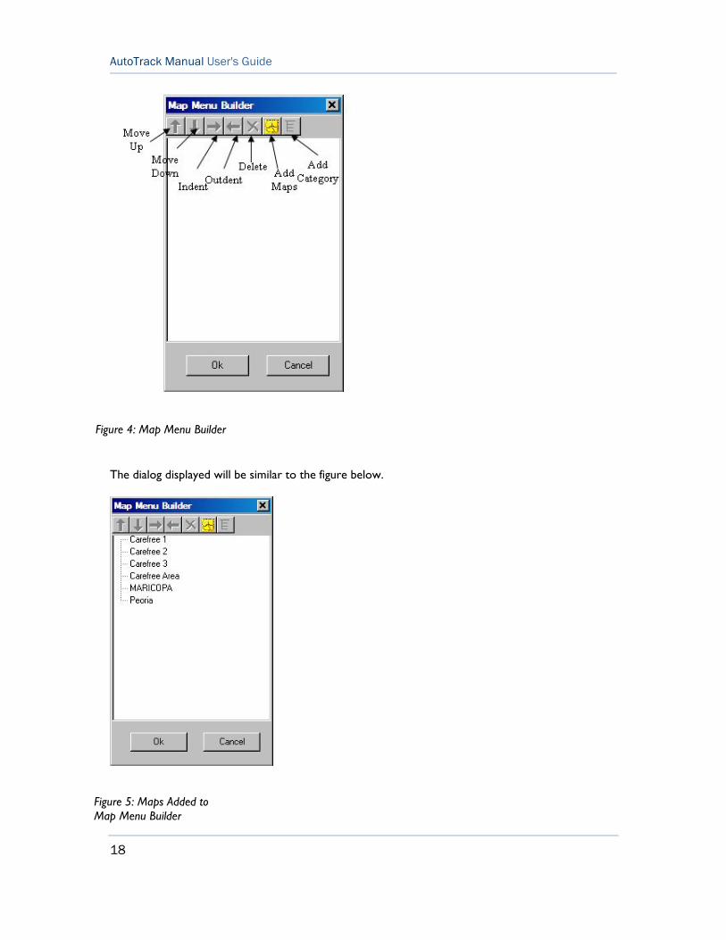
To add to the maps map menu, select Build Map Menu... from the Settings menu to display the dialog shown below. To add new maps to the menu press the Add Maps button. A standard open file dialog box will appear in the Map folder within the AutoTrack application. Note: The Map directory is the default directory; however, the maps you use may be stored anywhere on your hard disk. Select one or more maps and press Open. Multiple maps may be selected by holding down the Ctrl key while clicking on the map files.
18
AutoTrack Manual User's Guide
The dialog displayed will be similar to the figure below.
Figure 4: Map Menu Builder
Figure 5: Maps Added to Map Menu Builder
19
Chapter 4 Using AutoTrack
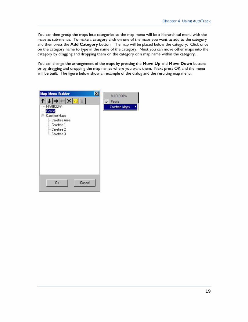
You can then group the maps into categories so the map menu will be a hierarchical menu with the maps as sub-menus. To make a category click on one of the maps you want to add to the category and then press the Add Category button. The map will be placed below the category. Click once on the category name to type in the name of the category. Next you can move other maps into the category by dragging and dropping them on the category or a map name within the category.
You can change the arrangement of the maps by pressing the Move Up and Move Down buttons or by dragging and dropping the map names where you want them. Next press OK and the menu will be built. The figure below show an example of the dialog and the resulting map menu.

20
AutoTrack Manual User's Guide
ENTERING AUTO TUNE CHANNELS
AutoTrack can tune channels by selecting them from the Channels menu. It is not necessary to setup channels; however, if you use certain frequencies often you may want to set them up as channels. To enter channels select Edit Channels... from the Channel menu. A dialog similar to the one shown below is displayed. In column 1 type in the frequency in MHz of the channel. In column 2 you can add a name you would like to use to refer to the channel. This name will appear under the Channel menu. If you leave this blank AutoTrack will display the frequency in the Channel menu. Click in the third column if you would want to disable the channel so that it will not be displayed in the Channel menu. This feature can be used if you use a certain group of frequencies in some instances and others in another instance. The fourth column will automatically select the antenna that will be selected if you have an antenna system with the DDF6071 or DDF6076 antenna switch installed
To delete a channel simply delete its frequency from the table.
The import feature allows a user to import channel data from a comma separated variable (.csv) file. The format of the file must be as follows
fff.ffffff,nnnnnn<CR><LF>
where fff.fffff is the channel frequency in MHz, nnnnnn is the channel name, and <CR><LF> are the carriage return and line feed characters respectively. A simple way to make a .csv file is to use Microsoft Excel and save the file as .csv.
To import the channels from a file press the Import button and a file open dialog will open. Select the desired file and the frequencies will be imported. BearingTrack will give you an option to delete the current frequencies or add the imported channels to the current list.
Figure 6: Use the Channel Select Dialog to Program in Frequently used Frequencies

21
Chapter 4 Using AutoTrack
SETTING THE COM PORT
In the Settings menu use the Serial Port menu item to select the serial port you are using on your computer. The program defaults to COM1 but any serial port can be used.
At this point AutoTrack should be receiving data from the GPS receiver and compass. To check if the program is receiving data, select Display COM Data (see "Displaying Raw Data from COM Port" on page 27)... from the View menu. Each second you should see a VTG (GPS), GGA (GPS), and HDM (Compass) message in the Received text box. If you do not see these messages
Make sure you have power applied to all the components
Make sure all the components are connected correctly and securely
Make sure your you've selected the proper serial port
CALIBRATING THE COMPASS
After you mount the roof pod to your vehicle it is important to calibrate the compass to the magnetic environment of your vehicle. Prior to calibrating the compass make sure you are in a clear area away from any magnetic materials and that you can drive your car in a circle. With the program in the off mode, select Calibrate Compass from the Setup menu. The program will instruct you on the required maneuvers and data entry required to complete the calibration.
Note: A compass is not required to use AutoTrack; however, if a compass is not used the vehicle must be moved after AutoTrack is put in the run mode so that the GPS receiver can calculate a heading.
SETTING UP THE GPS
The GPS receiver used must provide ONLY the standard GGA and VTG messages at a rate of once per second. The DDF6074 is factory programmed to provide these messages. If you use a different GPS receiver you must program to provide these messages.


23
23
RUNNING AUTOTRACK
To run AutoTrack, first make sure you are displaying a map of your general location. Next press the Run button. After pressing the Run button, your present location should be displayed on the screen as a small square with a number in its center.
Next tune your receiver to the frequency of the source you want to find. You can tune to the frequency by selecting an item from the Channel menu, by selecting Tune Receiver... from the Settings menu, or by simply tuning your receiver as you normally would. When the receiver detects a signal, the DDF6100/DDF6002 calculates a bearing and sends it to AutoTrack. AutoTrack will then display a line-of-bearing emanating from your present location toward the detected RF source as shown in the Figure below.
Figure 7: Line-of-Bearing is Displayed by AutoTrack
24
AutoTrack Manual User's Guide
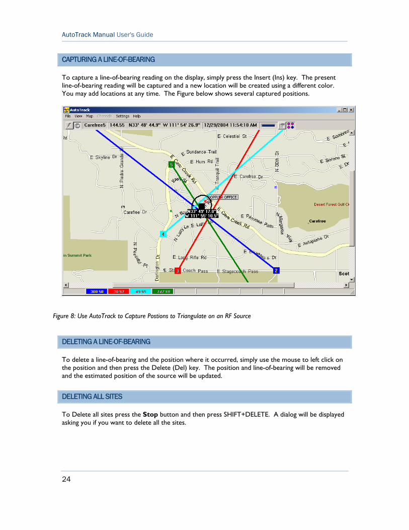
CAPTURING A LINE-OF-BEARING
To capture a line-of-bearing reading on the display, simply press the Insert (Ins) key. The present line-of-bearing reading will be captured and a new location will be created using a different color. You may add locations at any time. The Figure below shows several captured positions.
DELETING A LINE-OF-BEARING
To delete a line-of-bearing and the position where it occurred, simply use the mouse to left click on the position and then press the Delete (Del) key. The position and line-of-bearing will be removed and the estimated position of the source will be updated.
DELETING ALL SITES
To Delete all sites press the Stop button and then press SHIFT+DELETE. A dialog will be displayed asking you if you want to delete all the sites.
Figure 8: Use AutoTrack to Capture Postions to Triangulate on an RF Source
25
Using AutoTrack
DISPLAYING DATA
AutoTrack contains features that allow you to view data being received from the components in several different ways.
DISPLAYING THE DIRECTION FINDER BEARING
The bearing measured by the direction finder relative to the vehicle can be displayed by selecting Display Bearing... from the View menu. This display is particularly helpful as you get closer to the RF source. The lines of bearing displayed on the map are always relative to North while those displayed on the bearing display and on the direction finder front panel are relative to the vehile (up = straight ahead). Selecting this menu item will display a compass rose with an arrow pointing in the direction of the bearing. The compass rose is semi-transparent so you can see the map in its background. To adjust the brightness right click on the bearing display and select Adjust Brightness on the pop-up menu. A slider bar will appear on the right side of the bearing display allowing you to adjust the brightness of the display.
The bearing display can be positioned anywhere on your computer screen; however, if you would like AutoTrack will automatically center it on the currently active site. To select this option right click on the bearing display and select Center Bearing Display on Active Site.
DISPLAYING THE ESTIMATED POSITION OF THE SOURCE
Using two or more captured lines-of-bearing, AutoTrack will estimate the location of the RF source. It displays this location as a black square with the latitude and longitude of the estimated location beneath the square as shown in the previous Figure (see "Capturing a Line-of-Bearing" on page 24). To display the estimated location, select Show Estimated Position from the View menu.
95% CONFIDENCE ELLIPSE
The 95% Confidence Ellipse displays the area in which AutoTrack calculates that there is a 95% chance that the RF source resides. This ellipse is calculated based on the assumption that each direction finder has an error standard deviation of 5 degrees. Location and multi-path effects can affect direction finder errors. To display the ellipse select Show 95% Confidence Ellipse from the View menu. The previous Figure (see "Capturing a Line-of-Bearing" on page 24) shows an example of the ellipse.

26
AutoTrack Manual User's Guide
VIEWING THE LOCATIONS
After you have captured some sites you can get a text view of the results by selecting View Locations... from the View menu. A dialog similar to the one shown below will be displayed, showing the site number, the site location, the line-of-bearing and the signal strength. The coordinates of the estimated location are also shown. The far left column of the displayed table can be used to disable locations on the screen. Once disabled a location is not used in the position estimate.
Figure 9: Text View of the Captured Locations on the Map

27
Using AutoTrack
DISPLAYING DATA FROM THE SYSTEM COMPONENTS
Select Display Incoming Data.. from the View menu. The GPS, compass, and direction finder data that is being sent will be displayed as shown in the Figure below.
DISPLAYING RAW DATA FROM COM PORT
To view the data as it is received at the COM port, select Display Comm Data... from the View menu. An example of the data is shown in the Figure below. Received messages beginning with $GP are GPS messages; messages beginning with $HC are compass messages; messages beginning with $DF are direction finder messages; and all messages ending with the word HEX are receiver messages.
Figure 10: Data from the Components are Displayed
Figure 11: Data Received and Sent by AutoTrack are Displayed

28
AutoTrack Manual User's Guide
MANIPULATING THE DISPLAY
When running AutoTrack, at any time you can zoom in, zoom out, scroll or change the displayed map.
To zoom in select Zoom In from the View menu or right click on the screen and select Zoom In. If you right click the map will zoom in with the point you clicked on in the center of the screen.
To zoom out select Zoom Out from the View menu or right click on the screen and select Zoom Out.
To scroll the map, put the mouse in the scroll bars and press the left mouse button.
To change the displayed map, select the name of the map from the Map menu.

29
Using AutoTrack
TUNING THE RECEIVER
AutoTrack is designed to communicate with ICOM receivers using the CIV serial format. If you are using an ICOM receiver you can tune the receiver either by selecting channels from the Channels menu or by selecting Tune Receiver from the Settings menu.
You can use the mouse to select a channel from the Channels menu or you can type CTRL+# where # is a number between 0 and 9. Adding and deleting channels from this menu is explained in Entering Auto Tune Channels (on page 20)
Selecting Receiver (CTRL+T) from the Settings menu displays the dialog shown below. You can change frequencies by turning the dial, hitting one of the M buttons, typing in the frequency and hitting the Set button, or using the arrow keys to set the frequency. If the frequency does not match one of the channels in the Channel menu, the Save button will be shown and you can press Save to add the frequency to the Channel menu. The M buttons refer to the same channels as are shown in the Channel menu. If you are using an ICOM R8500 or AOR AR5000 receiver you can adjust the squelch, volume, and attenuator settings for the receiver. If you are using and AOR AR8600 you can turn the attenuator off and on and adjust the squelch.
Note: When using an AR5000 or AR8600 receiver, sending commands to them will lock the front panel. To unlock it press the Clear button on the front panel. Also when you adjust the squelch setting on the AR8600 that squelch setting is now the minimum setting allowed from the front panel. If you want to use the front panel to adjust the squelch below the setting in AutoTrack you must se the Squelch value to 0 in AutoTrack.
Figure 12: The Receiver Dialog Allows You to Remotely Tune and Adjust the Receiver

30
AutoTrack Manual User's Guide
CONTROLLING THE DIRECTION FINDER
Selecting Direction Finder (CTRL+D) from the Settings menu will display the dialog shown below allowing you to change the settings of the direction finder. An explanation of these settings can be found in theDDF6100/DDF6002 manual.
Figure 13: The Direction Finder Dialog Allows You to Change the Direction Finder Settings

31
Using AutoTrack
VIRTUAL SITES
A virtual site is a site you can add to a map to aid you in locating an RF source. For instance if you had a partner using another direction finder, he could transmit to you his location and a bearing. With this information you can place a virtual site on the map and it will be used to estimate the position of the RF source.
To define a virtual site simply right click on the map and select Add Virtual Site from the pop up menu. A virtual site will be added where you clicked and a small text box will appear allowing you to enter the bearing. Enter the bearing in the text box and hit the Enter (return) key. To change the location of the virtual site click on the site and drag it to where you want it. To change the bearing right click on the site and select Set Bearing. The Figure below shows a screen with a virtual site defined. The virtual site is indicated by a V in the location square and the value of the bearing displayed in the lower right corner of the location square.
Figure 14: Virtual Locations Can Be Used to Help Locate an RF Site
32
AutoTrack Manual User's Guide
CALIBRATING TO A BEACON
AutoTrack can be calibrated by using RF sites at known locations on known frequencies (beacons) such as weather channels.
Note: If you are using an ICOM R8500 receiver, the DDF6100/DDF6002 is calibrated to this receiver so you should not have to calibrate the system.
To perform a calibration you must first define a beacon. To define a beacon right click on the displayed map and select Add Beacon from the pop up menu. Enter the beacon frequency and the name you would like use to refer to it. The beacon name will appear in the Beacons menu. You can move a beacon by clicking on it and dragging it to a new location. You can change its name and frequency by right clicking on it and selecting Edit Beacon.
To calibrate to the beacon, make sure you have a clear line-of-sight to the beacon and then select the beacon channel name from the Beacons menu. The program will change the frequency of the receiver (ICOM CIV receivers only) and then automatically perform the calibration. When the calibration is complete AutoTrack will resume operation in the state it was in prior to the calibration.
PLAYBACK
An important feature of AutoTrack 2.0 is its ability to record the data it receives and then play it back at a later time. Play back is enabled using the Options (see "General Options" on page 36) dialog. Once enabled all data received by AutoTrack is written to a file so that it can be played back and manipulated at a later time. Nearly all of the screen shots seen in this manual were created using the playback feature.
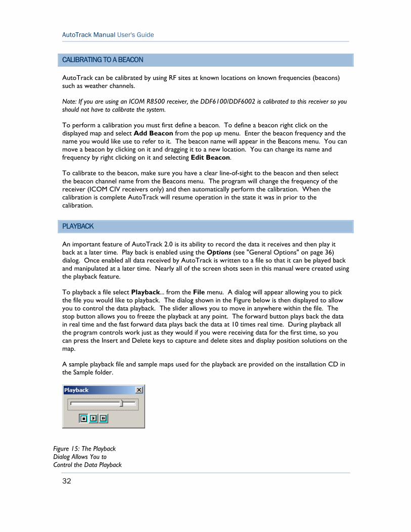
To playback a file select Playback... from the File menu. A dialog will appear allowing you to pick the file you would like to playback. The dialog shown in the Figure below is then displayed to allow you to control the data playback. The slider allows you to move in anywhere within the file. The stop button allows you to freeze the playback at any point. The forward button plays back the data in real time and the fast forward data plays back the data at 10 times real time. During playback all the program controls work just as they would if you were receiving data for the first time, so you can press the Insert and Delete keys to capture and delete sites and display position solutions on the map.
A sample playback file and sample maps used for the playback are provided on the installation CD in the Sample folder.
Figure 15: The Playback Dialog Allows You to Control the Data Playback
33
Using AutoTrack
LOGGING DATA
You can log the data in a tab delimited text file by pressing the Enable/Disable Logging (CTRL+L) button on the tool bar. The first time you press it a dialog box will appear allowing you to name log file. After you have selected a log file AutoTrack will continue to use this log file until you select New Log File from the File menu.
The log file can be viewed with a text editor or you can use the LogViewer application included with AutoTrack. LogViewer reads log files written by AutoTrack and displays the latest information first. LogViewer can be run from within AutoTrack by selecting View Log File from the File menu or as a separate program.


35
35
OPTIONS
AutoTrack has a number of Options available to allow the user to tailor AutoTrack to fit their preferences. This section explains these options. The options dialog is displayed by selecting Options from the Settings menu.
SITE OPTIONS
The site options dialog is shown below. The color and size of each site can be changed by selecting the the colors and site size from the drop down menus. If the Display no more the xxx sites is checked AutoTrack will display only the number of sites specified. If more sites are added, the oldest site is deleted prior to adding a new site. The default value for this setting is checked and 10 sites. The Display sites for a maximum time check box allows AutoTrack to automatically delete sites that have been displayed for more than the time setting. The default value is unchecked.
The Display Active Site Bearing for option will cause the bearing line from the active site to be removed from the screen after the set period of time has elapsed if no bearing data is received from the DDF6002. This option should be checked if the rf source you are seeking transmits on an infrequent basis. So, if you go around a corner and the heading changes you will not get incorrect lines of bearing displayed.
The Display Fixed Site Bearing for option is used when the AutoTrack is networked with a fixed site. AutoTrack will display the fixed site bearings for this set time if a bearing update is not received in the set time period.
Figure 16: The Site Options Dialog Allows You to Control the Appearance of the Sites

36
AutoTrack Manual User's Guide
GENERAL OPTIONS
The general options dialog is shown in the Figure below.
- Receiver. If the ICOM Receiver box is checked AutoTrack tries to communicate with the receiver using CIV. The CIV address of the receiver must match the value in RX Addr drop down combo box. If you are using an AOR receiver with a RS-232 connection you can simply plug in the AOR receiver into one of the serial ports on the DDF6002 or DDF6100.
- Latitude/Longitude Display. Using the option Display Seconds or Display Minutes in the Display menu you can control the format in which latitudes and longitudes are displayed. Latitude is measured as degrees north or south of the equator. A degree is divided into 60 minutes, and a minute into 60 seconds. As an example, the latitude north 35 degrees, 22 minutes, and 30 seconds is written as N 35° 22' 30.0". Alternatively, the same latitude can be given without seconds as N 35° 22.500'. Longitude is measured as degrees east or west of the Greenwich meridian. As an example, the longitude west 108 degrees, 12 minutes, and 15 seconds is written as W 108° 12' 15.0". Alternatively, the same longitude can be given without seconds as W 108° 12.250'.
- Display MGRS. Checking this box forces AutoTrack to display the positions on the map in the Military Grid Reference System instead of longitude and latitude.
- Display Options. Display options allows you to select how the current position and estimated RF source location are displayed. If Keep Current Location on Map is selected, Auto Track attempts to keep both the current active site and the estimated position of the RF source on the map. If it cannot keep both of them on the map it will keep the current location on it.
The Keep Estimated Source Location on Map behaves the same as Keep Current Location on Map except that if both locations cannot be displayed on the map the Estimated position is displayed.
The Keep Current Location centered on the Map option forces the current location to be centered on the map and as the vehicle moves, the map moves and the location stays centered.
The Keep Estimated Location centered on the Map option forces the estimated location to be centered on the map.
- Enable Playback. Checking Enable Playback forces AutoTrack to write a playback file whenever the program is in the run mode. If New File for Each Run is selected a new file is created each time the Run button is pushed the name of this file is PDOPyyyymmddhhmmssxx.pak where yyyy is the year, mm is the month, etc. when the file was created. If New File for Each Day is selected a new file is created each day the program is run and new data collected on that day is appended to the file.
- Center Bearing Display on Active Site. If this check box is checked the bearing display will move with the active site as it moves on the map. See Displaying the Direction Finder Bearing (on page 25).
37
Using AutoTrack
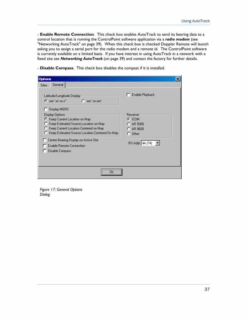
- Enable Remote Connection. This check box enables AutoTrack to send its bearing data to a control location that is running the ControlPoint software application via a radio modem (see "Networking AutoTrack" on page 39). When this check box is checked Doppler Remote will launch asking you to assign a serial port for the radio modem and a remote id. The ControlPoint software is currently available on a limited basis. If you have interest in using AutoTrack in a network with a fixed site see Networking AutoTrack (on page 39) and contact the factory for further details.
- Disable Compass. This check box disables the compass if it is installed.
Figure 17: General Options Dialog


39
39
NETWORKING AUTOTRACK
AutoTrack can be used to network the direction finder with other mobile and fixed sites. The mobile site acts as a data source and transmits its data to a fixed Network Control Site running Doppler's ControlPoint software. The ControlPoint software currently has limited distribution. For details on obtaining the software contact the factory. The Network Control Site controls the transmission of data. A radio modem connected to a serial port on the computer is used to receive commands and data from the Network Control Site and transmits the bearing data collected by AutoTrack. A tray application, Doppler Remote, runs along side of AutoTrack. Doppler Remote interfaces AutoTrack to the radio modem. For more details in setting up a network see Networking Doppler Systems Direction Finders which is included with the ControlPoint software on your installation CD.
If you need to change the serial port or the Remote ID you can double click on the tray icon or right click on it and select Open Doppler Remote (see below). You can also view the status of the remote connection by placing the mouse cursor on the tray icon. A pop up will be displayed indicating the status of the connection.
Figure 18: Right Click the Doppler Remote Tray Icon to View Doppler Remote Dialog
40
AutoTrack Manual User's Guide
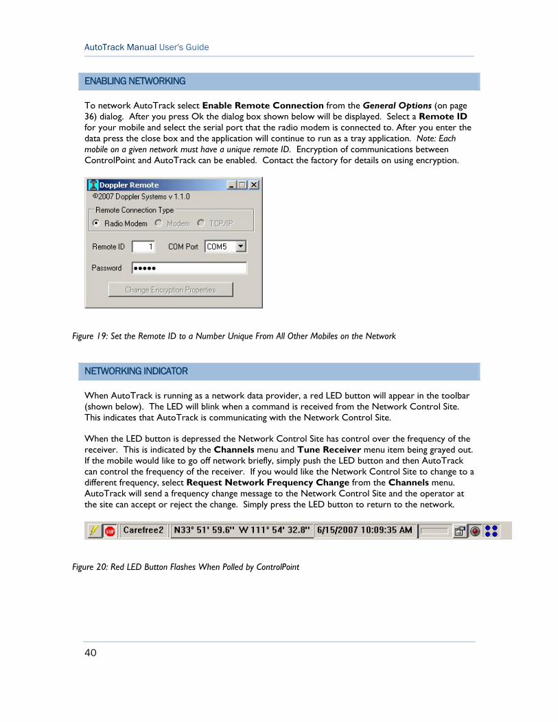
ENABLING NETWORKING
To network AutoTrack select Enable Remote Connection from the General Options (on page 36) dialog. After you press Ok the dialog box shown below will be displayed. Select a Remote ID for your mobile and select the serial port that the radio modem is connected to. After you enter the data press the close box and the application will continue to run as a tray application. Note: Each mobile on a given network must have a unique remote ID. Encryption of communications between ControlPoint and AutoTrack can be enabled. Contact the factory for details on using encryption.
NETWORKING INDICATOR
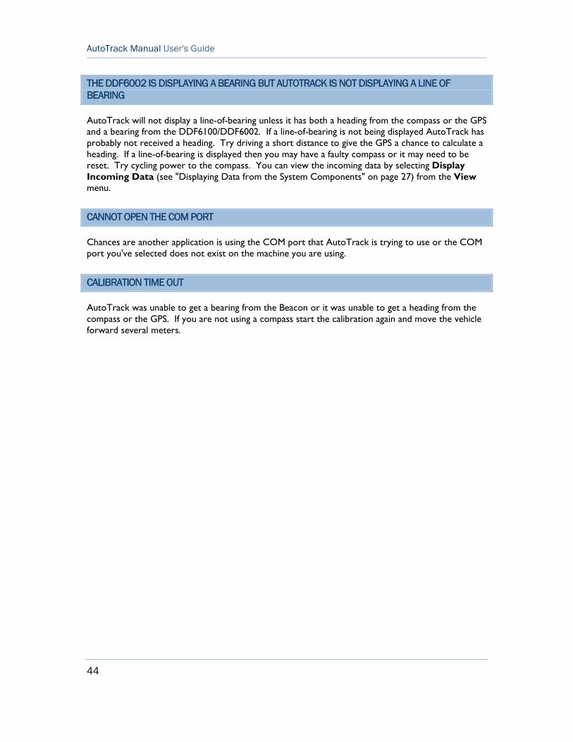
When AutoTrack is running as a network data provider, a red LED button will appear in the toolbar (shown below). The LED will blink when a command is received from the Network Control Site. This indicates that AutoTrack is communicating with the Network Control Site.
When the LED button is depressed the Network Control Site has control over the frequency of the receiver. This is indicated by the Channels menu and Tune Receiver menu item being grayed out. If the mobile would like to go off network briefly, simply push the LED button and then AutoTrack can control the frequency of the receiver. If you would like the Network Control Site to change to a different frequency, select Request Network Frequency Change from the Channels menu. AutoTrack will send a frequency change message to the Network Control Site and the operator at the site can accept or reject the change. Simply press the LED button to return to the network.
Figure 19: Set the Remote ID to a Number Unique From All Other Mobiles on the Network
Figure 20: Red LED Button Flashes When Polled by ControlPoint

41
Using AutoTrack
TEXT MESSAGING
The helper application Doppler Remote runs as a tray icon application. When Doppler Remote makes a valid connection with the Network Control Site running ControlPoint the tray icon menu contains an item enabling the text messaging feature as shown below.
To send a text message right click on the tray icon and select Text Message... Doppler Remote will display a window as shown below.
Type into the Send box and press the Send button to send a message to the Network Control Site. If the Network Control Site sends a message to the mobile prior to selecting this window, the window will automatically be displayed.
Figure 21: Text Message Menu
Figure 22: Text Messaging Window


43
TROUBLESHOOTING
This chapter discusses some of the more frequently encountered problems users have with AutoTrack.
IN THIS CHAPTER
Receiver Not Responding Dialog is Displayed.............................................. 43 AutoTrack is not displaying my position on the map.................................. 43 The DDF6002 is displaying a bearing but AutoTrack is not displaying a line of bearing................................................................................................................ 44 Cannot Open the COM Port............................................................................ 44 Calibration Time Out.......................................................................................... 44
RECEIVER NOT RESPONDING DIALOG IS DISPLAYED
AutoTrack is designed to work with ICOM receivers that employ CIV format in their serial communications or AOR receivers with a serial connection. If you are using another type of receiver, you must uncheck the ICOM receiver check box in the Options dialog.
If you are using an ICOM receiver make sure the CIV address of the receiver matches the CIV setting you've entered into AutoTrack. You can set the CIV address on the General tab of the Options dialog. See your receiver manual to learn how to determine the receiver's CIV address setting.
AUTOTRACK IS NOT DISPLAYING MY POSITION ON THE MAP
If your location is not displayed it's possible that the GPS receiver has not yet converged on a location solution or you are in a location where the GPS signals not being received. To see the raw data coming from your GPS, select Display Comm Data (see "Displaying Raw Data from COM Port" on page 27)... from the View menu. You may also select Display Incoming Data (see "Displaying Data from the System Components" on page 27)... to view the data after it has been decoded.
If you see incoming data that is being decoded properly, check to make sure you are using a map for your area and that the map has been properly calibrated using MapFix.
If you do not see and Comm data check your RS232 cable and connections. The required cable is a straight through cable DB9M to DB9F that has pins 2, 3, and 5 connected as a minimum.
Chapter 5
44
AutoTrack Manual User's Guide
THE DDF6002 IS DISPLAYING A BEARING BUT AUTOTRACK IS NOT DISPLAYING A LINE OF BEARING
AutoTrack will not display a line-of-bearing unless it has both a heading from the compass or the GPS and a bearing from the DDF6100/DDF6002. If a line-of-bearing is not being displayed AutoTrack has probably not received a heading. Try driving a short distance to give the GPS a chance to calculate a heading. If a line-of-bearing is displayed then you may have a faulty compass or it may need to be reset. Try cycling power to the compass. You can view the incoming data by selecting Display Incoming Data (see "Displaying Data from the System Components" on page 27) from the View menu.
CANNOT OPEN THE COM PORT
Chances are another application is using the COM port that AutoTrack is trying to use or the COM port you've selected does not exist on the machine you are using.
CALIBRATION TIME OUT
AutoTrack was unable to get a bearing from the Beacon or it was unable to get a heading from the compass or the GPS. If you are not using a compass start the calibration again and move the vehicle forward several meters.
45
The AutoDFTest utility program allows you to change all the settings in the direction finder. To use it you must connect the DDF6100/DDF6002 to your computer and AutoTrack not be running. An explanation of the direction finder settings is found in the DDF6100/DDF6002 manual.
Chapter 6 AUTODFTEST UTILITY PROGRAM


9 95% CONFIDENCE ELLIPSE • 25
A AUTODFTEST UTILITY PROGRAM • 45 AUTOTRACK IS NOT DISPLAYING MY
POSITION ON THE MAP • 43
C CALIBRATING THE COMPASS • 21 CALIBRATING TO A BEACON • 32 CALIBRATION TIME OUT • 44 CANNOT OPEN THE COM PORT • 44 CAPTURING A LINE-OF-BEARING • 25 CAPTURING A LINE-OF-BEARING • 24 COMPUTER REQUIREMENTS • 4 CONTROLLING THE DIRECTION FINDER
• 30 CREATING A MAP IMAGE • 9 CREATING MAPS • 7
D DELETING A LINE-OF-BEARING • 24 DELETING ALL SITES • 25 DISPLAYING DATA • 25 DISPLAYING DATA FROM THE SYSTEM
COMPONENTS • 43, 44 DISPLAYING DATA FROM THE SYSTEM
COMPONENTS • 27 DISPLAYING MAPS • 17 DISPLAYING RAW DATA FROM COM
PORT • 21, 43 DISPLAYING RAW DATA FROM COM
PORT • 27 DISPLAYING THE DIRECTION FINDER
BEARING • 37 DISPLAYING THE DIRECTION FINDER
BEARING • 25 DISPLAYING THE ESTIMATED POSITION
OF THE SOURCE • 25
E ENABLING NETWORKING • 40 ENTER CALIBRATION POINTS • 11 ENTERING AUTO TUNE CHANNELS • 29
ENTERING AUTO TUNE CHANNELS • 20
G GENERAL OPTIONS • 16, 33, 40 GENERAL OPTIONS • 37 GRAPHICS FILE FORMATS • 9
I IMPORTING THE IMAGE • 11 INSTALLATION • 5 INTRODUCTION • 3
L LOGGING DATA • 33
M MANIPULATING THE DISPLAY • 28
N NETWORKING AUTOTRACK • 38 NETWORKING AUTOTRACK • 39 NETWORKING INDICATOR • 40
O OPTIONS • 35 OVERVIEW OF THE PROGRAMS • 4
P PLAYBACK • 33
R RECEIVER NOT RESPONDING DIALOG IS
DISPLAYED • 43 RUNNING AUTOTRACK • 23
S SAVING THE MAP FILE • 12 SCANNING IN AN IMAGE • 9 SETTING THE COM PORT • 21 SETTING THE RECEIVER ADDRESS • 16 SETTING UP AUTOTRACK • 15 SETTING UP THE GPS • 21 SETTING UP THE HARDWARE • 15 SITE OPTIONS • 36
INDEX

AutoTrack Manual User's Guide
T TEXT MESSAGING • 41 THE DDF6002 IS DISPLAYING A BEARING
BUT AUTOTRACK IS NOT DISPLAYING A LINE OF BEARING • 44
TROUBLESHOOTING • 43 TUNING THE RECEIVER • 29 TYPOGRAPHICAL CONVENTIONS • 3
U USING AUTOTRACK • 13 USING GOOGLE EARTH • 10 USING MAPFIX • 11 USING MICROSOFT MAPPOINT • 9 USING MICROSOFT MAPPOINT • 10 USING THIS MANUAL • 4
V VIEWING THE LOCATIONS • 26 VIRTUAL SITES • 31