autonomous mission operations - nasa€¢ header segment ... – handles the faults which occurs...
TRANSCRIPT

Advancing Autonomous Operations for Deep Space Vehicles
Angie T. Haddock/NASAHoward K. Stetson/TBE‐NASASpaceOps Conference 2014May 2014
10
Autonomous Mission
Operations
1
https://ntrs.nasa.gov/search.jsp?R=20140010986 2018-06-22T02:12:15+00:00Z
10
Automated Operations Development for Advanced Exploration Systems ‐ Introduction
• Manned Deep Space Mission, with extreme communication delays with Earth based assets, presents significant challenges for the on‐board procedures content and the planned execution of the procedures.
• The Advanced Exploration Systems (AES), Autonomous Mission Operations (AMO) Project began to investigate the ability to create and execute “single‐button” crew initiated autonomous activities in January 2012.
• The NASA Marshall Space Flight Center (MSFC) led AMO team designed and built a fluid transfer hardware test‐bed called the Autonomous Fluid Transfer System (AFTS).
• The AFTS is a sub‐system target used for the investigations of intelligent procedures. Without operator intervention, these intelligent procedures can command and control, self‐monitor during fluid transfers, detect anomalies and faults, and isolate the fault and recover the procedures functions which was being executed.
• This presentation will detail the development of intelligent procedures for the AFTS and the autonomous plan execution capabilities which are being investigated.
2

10
Autonomous Fluid Transfer System
• AFTS is comprised of the following:– Two Fluid Tanks
• One for a source of supply and One for Multi‐Use• Each Tank contains a Pressure Sensor at the bottom of the tank• A Temperature Sensor• A Fluid Heater
– Two Command‐able Transfer Legs• Each contains a fluid pump, pressure sensors before and after each pump and a
flow meter after the pump.• An additional third flow meter is placed just before the Multi‐Tank for fault
tolerance of either transfer leg
– One Command‐able Return Transfer Leg• A single command‐able pump, which is used to simply return fluid back to the supply tank.• This return leg is semi‐automated since there are no flow meters or pressure sensors in use on
this return leg.
– One Manual leg, for pure manual operations– Arduino Controller
• Used for Command and Telemetry Interfaces3
10
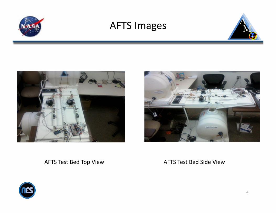
AFTS Images
4
AFTS Test Bed Top View AFTS Test Bed Side View
10
AFTS Procedure System ArchitectureTimeliner‐TLX System
• Met the procedural development requirements of the operation concept
• Timeliner‐TLX System is both a procedure development environment and a procedure execution engine
• Timeliner‐TLX procedures are packaged as a file called a bundle and the procedures within the bundles are independently executed sequences which share global data within the bundle and global data between all bundles for data exchanges between procedures.
• Timeliner‐TLX System has built in sequence status telemetry available to all sequences, which allows a sequence’s execution status to be available to all sequences.
5
10
AFTS Procedure System ArchitectureHAL9000 Space Operating System
• A prototype system which encompasses both procedure execution and the real‐time planning and re‐planning of procedures.
• The execution component architecture is currently being utilized for the International Space Station (ISS) Payload Operations.
• The HAL9000 Timeliner‐TLX architecture divides operations into 9 auto‐operators:– HALMain, GN&C, Power, ECLSS, Comm, Propulsion, Safety, Robotics and Activity– Each auto‐operator operates within a separate Timeliner‐TLX Engine and has a suite of
bundles which contain the intelligent procedures required to operate the specific sub‐system
• The AFTS Test‐Bed uses only three of the auto‐operators, packaged into 3 bundles– HALMain
• The “Mission Manager” responsible for the startup and utilization of the AFTS, and procedure installment for Safety and ECLSS
– Safety• Responsible for monitoring all Flight Rules and conditions associated with safe operations.
– ECLSS• Contains intelligent procedures related to fluid transfers
6

10
7
AFTS Test Bed
Tank 1
Tank 2
Controller
Pump 1 Pump 2
T1
F1
P2
V1
ReturnPump
MV4
MV1 MV2 MV3
F3
F2
V2
H1
H2
P1
P6
P4
Data/Pwr
P3 P5
Data/Pwr
T2
Primary Backup
Free
Flow Leg
Return Leg
RecirculationPump
Three way valve
FilterMV = Manual ValveV = Command‐able ValveH = HeaterF = Flow MeterP = Pressure SensorT = Temperature Sensor
10
AFTS Procedure Design
• The AFTS procedure architecture allocated 3 operators: – HALMain, Safety, ECLSS
• The HALMain Timeliner‐TLX initialization procedure becomes active automatically upon installation.
• After the initialization, the Safety procedures are installed and safety monitoring becomes active automatically.
• Once HALMain determines it is safe to operate the AFTS, it then installs the ECLSS procedures for crew availability.– This is inherently safe as the transfer procedures are not available for
activation unless the AFTS is deemed operational.
• Once power is removed from the AFTS, HALMain monitoring procedures remove the ECLSS auto‐procedures which inhibit inadvertent commanding to the sub‐system by procedure execution
• The autonomous software installation and removal functionally frees memory allocated to the Timeliner‐TLX Engine (which executes the procedures); always minimizing the amount of memory needed for procedures based upon sub‐systems being powered/un‐powered. 8

10
AFTS Procedure DesignSafety Timeliner‐TLX Procedure
• The Safety Timeliner‐TLX procedures become active automatically upon installation and begin monitoring all safety rules: The following rules are enforced:– Maximum Temperature of the Supply Tank Fluid as 75 degrees F– Maximum Temperature of the Multi‐Use Tank Fluid as 75 degrees F– Maximum Fluid Level of 27 gallons in the Supply Tank– Maximum Fluid Level of 27 Gallons in the Multi‐Use Tank– Supply Tank Heater must be powered off when fluid level is below the heater
interface– Multi‐Use Tank Heater must be powered off when fluid level is below the
heater interface– No two pumps in the ON state simultaneously
9

10
AFTS Procedure DesignECLSS Timeliner‐TLX Procedure
• The ECLSS Timeliner‐TLX procedure provides the “Single Button” intelligent crew activities.
• Each transfer function is required to validate the crew activity before beginning operations.
– Ensure fluid quantities are available, ensure quantities can be transferred
• Each transfer activity contains Fault Detection Isolation and Recovery (FDIR)– The procedure messages the crew on all failure detections and actions being
taken by the procedure and also directs maintenance when failures are encountered.
– The Procedure safes the transfer leg and recovers the transfer function on the alternate leg to completion.
• Each single button activity contains the specific FDIR logic required for the fluid transfer being requested. This results in an operations paradigm of an auto‐operator which is employed only when needed and when desired, and only a single crew action is required.
• This capability is a great advancement to flight operations for crew and/or ground operator work reduction.
10

10
AFTS Procedure DesignAFTS ECLSS Autonomous Activities
• ¼ Tank Primary Transfer• ¼ Tank Backup Transfer• ½ Tank Primary Transfer• ½ Tank Backup Transfer• Full Tank Primary Transfer• Full Tank Backup Transfer• X Gallon Primary Transfer• X Gallon Backup Transfer• Supply Tank Heater On• Supply Tank Heater Off• Multi-Use Tank Heater On• Multi-Use Tank Heater Off• Set Supply Tank Temperature• Set Multi-Use Tank Temperature• ¼ Tank Return Transfer• ½ Tank Return Transfer• Full Tank Return Transfer• X Gallon Return Transfer
11

10
Procedure Format
• The architecture of each Procedure is broken into seven segments.• Header Segment
– Commented information section describing the functional capability, authorship, and version control information.
• Declaration Segment– Defines internal variables used within the procedure.
• Validation Segment– Defines the checks to be performed prior to the actual command execution of the activity.
• Initialization Segment– Defines the command and command end items checks which are performed to begin the function
being requested.
• Monitoring Segment– Defines the parameters to monitor and rate of monitoring while the function is being performed,
and determines whether the function or activity has completed, this segment also has fault detection implemented once the function has completed and the sub‐system is being safed.
• FDIR Segment 1– Handles faults which occurs during the procedure execution and is responsible for the actions which
takes places for safing and recovery.
• FDIR Segment 2– Handles the faults which occurs during the procedure initialization.
12
10
Planning Autonomous Activities
• The ECLSS fluid transfer procedures are wholly contained activities.
• The activity duration and resource utilizations can be quantified upon the first execution during testing and can be easily planned thereafter.
• For planning purposes, the results of a test execution can derive the time it requires to transfer a fixed quantity.
• As activities are performed, resource utilizations can be updated to affect the activity duration time and power requirements.
13
10
Autonomous Plan Execution
• The AFTS intelligent procedures are activities which execute separately and require fairly fixed resources for both nominal and off‐nominal execution. This made the generation of a plan of transfer activities relatively simple.
• Two concepts were selected as potential candidates and tested.– Master Bundle: concept from early ISS Payload Operations– HAL9000 System “Auto Mode”
• The HAL9000 has two different ways of executing activities autonomously.– All activities are wholly contained intelligent procedures where the Planning Engine starts each activity; execution
mode selected (Master Bundle/ISS OSTP oriented).– “Full Auto” mode design where the plan is contained in time ordered state code arrays for every device in the activity.
• The AFTS Master Bundle was created manually and was based upon relative time from the start of execution rather than absolute time and insures no two activities are in execution simultaneously.
• The master sequence first retrieves the current time and then starts each activity relative to the current time it was collected.
• The start of an activity is conditional as the master sequence ensures the previous activity has been completed.
• The master sequence continuously verifies the sequence’s status to determine if the activity has completed nominally or off‐nominally.
• Multiple plan executions were accomplished with the AFTS Master Bundle with failure injections during transfer operations and failover activations and the FDIR capabilities performed as programmed.
14

10
Alternate Way for Autonomous Execution
• “Full Auto” execution mode has the capability of executing the time tagged state codes in time order.
• The differences in execution between wholly contained intelligent Timeliner‐TLX procedures and the HAL9000 Execution Component “Full Auto” execution mode lies within the embedded FDIR employed within the intelligent procedures, versus a separate monitor which only knows whether a device or sub‐system has failed.
• The intelligent procedure has the specific to the actual safing which is required at any specific point in the procedure, while the FDDR Monitor has the generic safing capability and needs to check all devices for a safe state and command the ones which are needed.
• Timeliner‐TLX provides the identification and status of all installed procedures which are in execution as a built‐in feature of this procedure system, which allows the FDDR Monitor more intelligence as it pertains to the higher level function which was being performed at the point of failure
• The FDDR Monitor can detect whether a Timeliner‐TLX sequence is stopped by error, stopped by command from the crew or in a finished condition.
15
10
Execution Comparison
• After plan execution with both execution methods. The Master Bundle concept appears to the better operational implementation for the AFTS due to the lack of a full HAL9000 suite of planning engines and FDDR monitors. This is dependent upon having intelligent procedures, as failure without recovery may impact the activities which follow in the plan.
• Intelligent procedures with full embedded FDIR increases the success percentage of Master Bundle execution as each activity eventually comes to completion and the system is in a safe state for the next activity.
• The Full Auto Mode execution does not have procedures in operation, does not have knowledge of the higher level function being performed, and does not know the quantity of fluid being transferred. This responsibility is distributed to the Planning Engines (Executives) within the HAL 9000 architecture and creates a new plan.
• An autonomous operation requires monitoring and the capability to track real‐time execution with planned events programmatically, results in less crew dependency and faster notification when the plan is not met.
• Intelligent procedures can reduce the amount of external monitoring and planning which is required since these functions are wholly encompassed within the procedure. 16

10
Future Work
• An increase in complexity of the AFTS system is desired to fully exercise and expand on the distributed operations realized by the procedure architecture.
• Additional pressure sensors will be added to the tanks to increase fault tolerance and logic and additional recirculation pumps and filters will be added which will only increase the operations requirements and make temperature control available.
• Adding complexity and additional flight rules will help prove the procedure architecture and its understanding of how adaptable it could be for multiple systems to be operated.
• The AMO Team is in the process of developing these type of procedures to operate an EXPRESS Payload Rack on‐board the International Space Station during Summer 2014.
• The procedures will be proved on the ground before interfacing them on‐board for eventual crew usage.
• The intent of the EXPRESS operations is to provide single action functions for operating the rack to include, thermal flow rate control and valve speed monitoring, powering and un‐powering, smoke detection enablement/disablement and payload configuration, with embedded FDIR whenever possible.
• The capability will allow the crew to activate/de‐activate an EXPRESS rack with a single action.
17
10
Autonomous Mission
Operations
10
Questions?
18

10
Acronym List
19
AES AFTS AMO COMM ECLSS EXPRESS FDDR FDIR GNC
Advanced Exploration Systems Autonomous Fluid Transfer System Autonomous Mission Operations Communications Environmental Control and Life Support System EXpedite the PRocessing of Experiments for Space Station Racks Fault Detection, Diagnostics and Response Fault Detection Isolation and Recovery Guidance , Navigation and Control
HAL Higher Active Logic ISS MOL MSFC NASA OSTP TBE
International Space Station Mission Operations Lab Marshall Space Flight Center National Aeronautics and Space Administration Onboard Short Term Plan Teledyne Brown Engineering
10
Glossary
20
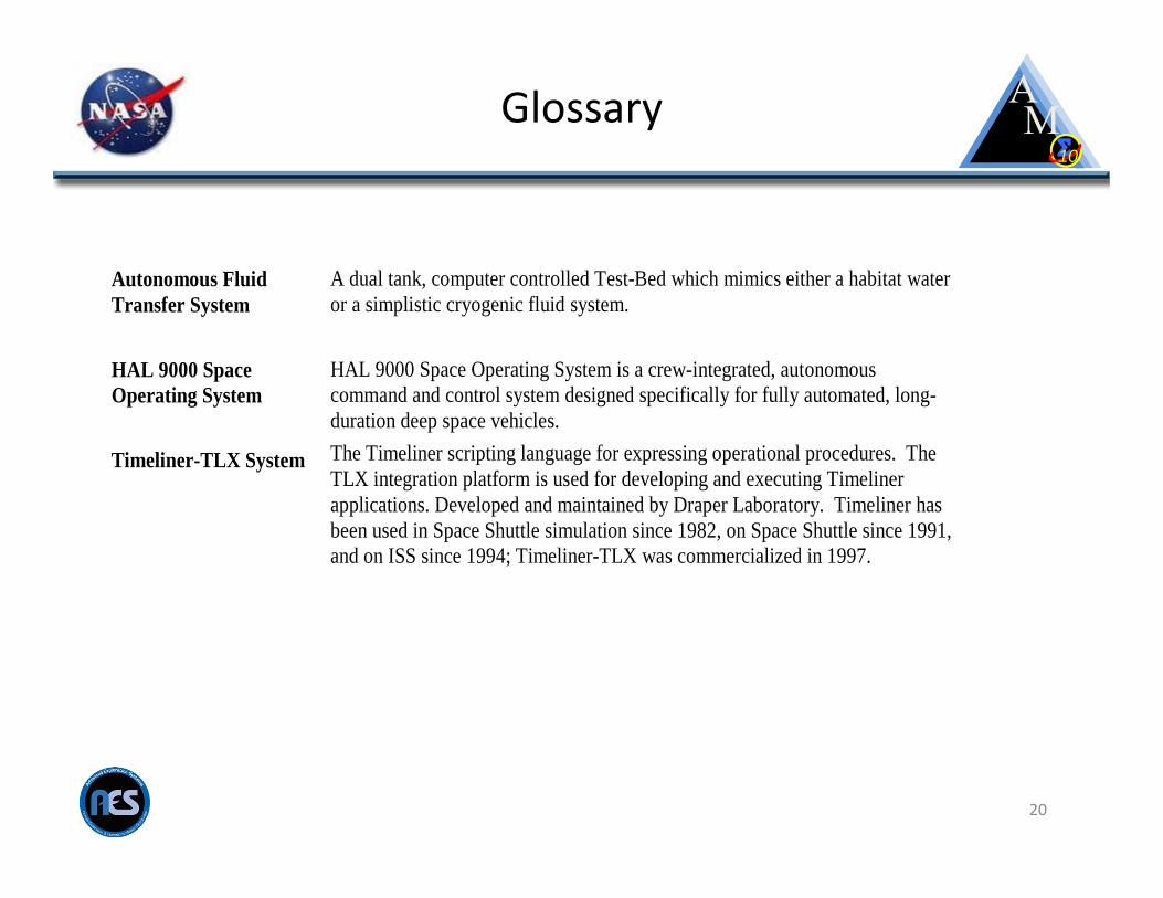
Autonomous Fluid Transfer System HAL 9000 Space Operating System Timeliner-TLX System
A dual tank, computer controlled Test-Bed which mimics either a habitat water or a simplistic cryogenic fluid system. HAL 9000 Space Operating System is a crew-integrated, autonomous command and control system designed specifically for fully automated, long-duration deep space vehicles. The Timeliner scripting language for expressing operational procedures. The TLX integration platform is used for developing and executing Timeliner applications. Developed and maintained by Draper Laboratory. Timeliner has been used in Space Shuttle simulation since 1982, on Space Shuttle since 1991, and on ISS since 1994; Timeliner-TLX was commercialized in 1997.