autonomous flight control for a titan exploration aerobot
TRANSCRIPT

AUTONOMOUS FLIGHT CONTROL FOR A TITAN EXPLORATION AEROBOT
Alberto Elfes1, James F. Montgomery1, Jeffery L. Hall1, Sanjay S. Joshi2, Jeffrey Payne2,Charles F. Bergh1
1Jet Propulsion Laboratory, Pasadena, CA 91109, USA. Email: {elfes, monty, jeffery.l.hall, cfb}@jpl.nasa.gov2 University of California, Davis, California 95616, USA. Email: {maejoshi, jwpayne}@ucdavis.edu
ABSTRACT
Robotic lighter-than-air vehicles, or aerobots, provide astrategic platform for the exploration of planets and moonswith an atmosphere, such as Venus, Mars, Titan and the gasgiants. Aerobots have modest power requirements, extendedmission duration and long traverse capabilities. They canexecute regional surveys, transport and deploy scientificinstruments and in-situ laboratory facilities over vastdistances, and also provide wide-area surface sampling. Withthe arrival of the Huygens probe at Saturn’s moon Titan onJanuary 14, 2005, there is considerable interest in a follow-onmission that would use a substantially autonomous aerobot toexplore Titan’s surface. In this paper, we discuss steps towardsthe development of an autonomy architecture, and concentrateon the autonomous flight control subsystem. Two researchdirections are described: first, the development of a highlyaccurate aerodynamic airship model and its validation; second,an initial implementation of the flight control system and theresults obtained from autonomous flight tests conducted in theMojave desert. We conclude by outlining further issues forresearch.
1. INTRODUCTION
Exploration of the planets and moons of the Solar Systemhas up to now relied on remote sensing from Earth, fly-byprobes, orbiters, landers and rovers. Remote sensing probesand orbiters can only provide non-contact, limited resolutionimagery over a small number of spectral bands; landersprovide high-resolution imagery and in-situ data collectionand analysis capabilities, but only for a single site; whilerovers allow imagery collection and in-situ science acrosstheir path. The fundamental drawback of ground-basedsystems is limited coverage: in past or planned explorationmissions, the rover range has varied from approximately 130mfor the 1997 Sojourner mission, to currently 4.0 km for theMars Exploration Rovers, to tens of kilometers for theteleoperated Lunokhod rovers.
There is currently a strategic gap in robotic explorationtechnologies for systems that combine extensive geographicalcoverage with high-resolution data collection and in-situscience capabilities. For planets and moons with anatmosphere, this gap can be addressed through aerial vehicles.In the Solar System, in addition to Earth, the planets Venusand Mars, the gas giants (Jupiter, Saturn, Uranus and Neptune)and the Saturn moon Titan have significant atmospheres.
Aerial vehicles that have been considered for planetaryexploration include airplanes and gliders, helicopters, balloons[Kerzhanovich 2002] and airships. Flight time for glidersdepends heavily on wind and updraft patterns, which in turnconstrain their surface coverage, while airplanes andhelicopters expend significant energy resources simply stayingairborne [Elfes 2001, Elfes 2003].
The NASA 2003 Solar System Exploration Roadmapidentifies aerial vehicles as strategic platforms for theexploration of Mars, Venus and Titan [NASA 2003]. It alsodefines advanced autonomy technologies as a high prioritydevelopment area for the operation of aerial explorationvehicles. In this paper, we discuss the advantages andchallenges involved in aerobot exploration of Titan and therequired autonomy capabilities. We provide an outline of theaerobot autonomy architecture under development, anddescribe the JPL aerobot testbed. We also discuss thedevelopment of a highly accurate aerodynamic airship modeland its validation, as well as an initial implementation of theflight control system and the results obtained fromautonomous flight tests conducted in the Mojave desert.
2. AEROBOTS FOR PLANETARY EXPLORATION
Lighter-than-atmosphere (LTA) systems providesignificant advantages for planetary exploration due to theirpotential for extended mission duration, long traverse, andextensive surface coverage capabilities. Robotic airships, inparticular, are ideal platforms for airborne planetaryexploration. Airships have modest power requirements, andcombine the extended airborne capability of balloons with themaneuverability of airplanes or helicopters. Theircontrollability allows precise flight path execution forsurveying purposes, long-range as well as close-up groundobservations, station-keeping for long-term monitoring ofhigh-value science sites, transportation and deployment ofscientific instruments and in-situ laboratory facilities acrossvast distances to key science sites, and opportunistic flightpath replanning in response to the detection of relevantscience sensor signatures. Furthermore, robotic airshipsprovide the ability to conduct extensive surveys over bothsolid terrain and liquid-covered areas, and to reconnoiter sitesthat are inaccessible to ground vehicles.
Implementation of these capabilities requires achieving ahigh degree of vehicle autonomy across a broad spectrum ofoperational scenarios. An integrated set of enablingtechnologies for autonomous aerobot navigation and aerial

exploration is currently not available, and is the core focus ofthe research being developed at JPL by the authors [Hall2002a, Hall 2004, Elfes 2003, Elfes 2004].
3. SATURN’S MOON TITAN
NASA’s 2003 Solar System Exploration Roadmapspecifies a follow-on Titan mission with an in-situ vehicle as ahigh priority after the Cassini-Huygens mission. Titan is thelargest moon of Saturn, with a radius of 2,575 km. It has anatmosphere with a surface density of 5.55 kg/m3 (4.6 times thedensity of the Earth's atmosphere at sea level), and anestimated composition of 95% nitrogen, 3% methane and 2%argon. The surface pressure is approximately 1.5 bar, and thegravity at the surface is 1.35 m/s2 (1/7 of the gravity of Earth).The surface temperature is approximately –180o C.
The upper atmosphere of Titan has a thick haze, causedby sunlight-induced chemical reactions of methane, whichshrouds the surface of Titan from visual observation (Fig. 1).As a result, very little is known of Titan’s geography andgeology. Early Voyager fly-by observations and recent HubbleSpace Telescope (HST) images in the near-infrared spectrum(0.85 to 1.05 microns) indicated the possible existence ofcontinental masses composed of solid rock and frozen waterice, and of liquid bodies potentially composed of liquid ethaneand methane [Hall 2002a, Hall 2002b, Lorenz 2000].Additional long-term observations have also providedindications of weather on Titan, including clouds and storms.
The successful descent of the Huygens probe to thesurface of Titan on January 14, 2005 has provided spectacularimages of a very complex terrain (Fig. 2). While the data isstill in the early stages of processing and analysis, and muchwill be learned in the coming months, it is clear that manyscientific questions will remain unanswered, particularly in theareas of weather and seasonal variability, subsurfacemorphology, and the composition and distribution of surfaceorganic material [Chyba 1999], leading to the requirement fora follow-on mission.
4. AEROBOT AUTONOMY ARCHITECTURE
The main challenges for aerobot exploration of Titaninclude: large communication latencies, with a round trip lighttime of approximately 2.6 hours; extended communicationblackout periods with a duration of up to 9 Earth days, causedby the rotation of Titan and its orbital occlusion by Saturn;extended mission duration, currently projected to be on theorder of six months to one year; and operation in substantiallyunknown environments, with largely unknown wind patterns,meteorological conditions, and surface topography.
These challenges impose the following capabilityrequirements on a Titan aerobot: vehicle safing, so that thesafety and integrity of the aerobot can be ensured over the fullduration of the mission and during extended communicationblackouts; accurate and robust autonomous flight control,including deployment/lift-off, long traverses, hovering/station-keeping, and touch-and-go surface sampling; spatial mapping
Fig. 1: False-color image of Titan, using ultraviolet and infrared images takenby Cassini's imaging science subsystem on Oct. 26, 2004. Red and greencolors represent infrared wavelengths and show areas where atmosphericmethane absorbs light. These colors reveal a brighter (redder) northernhemisphere. Blue represents ultraviolet wavelengths and shows the highatmosphere and detached hazes. Bright surface areas indicate continentalmasses, while dark areas may indicate regions with liquid methane and ethaneor basins of deposited material. Source: NASA/JPL/Space Science Institute,ref. PIA06139.
Fig. 2: Titan surface image taken by the Huygens probe during descent. It wastaken at an altitude of 16.2 km, with a resolution of approximately 40 m/pixel.An early interpretation suggests the presence of a drainage system in the“highlands” (lighter areas) that leads into a darker region that may be a basinof deposited hydrocarbons. Methane clouds and what may be amethane/ethane fog close to the “shore” can be seen. Source:ESA/NASA/JPL/University of Arizona.

and self-localization in the absence of a global positioningsystem and probably of a magnetic field on Titan; andadvanced perceptual hazard and target recognition, trackingand servoing, allowing the aerobot to detect and avoidatmospheric and topographic hazards, and also to identify,home in, and keep station over pre-defined science targets orterrain features. We have discussed elsewhere a broad range ofmission scenarios and identified the associated autonomyrequirements [Hall 2002b].
To address the aerobot autonomy capabilities requiredabove, we are developing an aerobot autonomy architecturethat integrates accurate and robust vehicle and flight trajectorycontrol, perception-based state estimation, hazard detectionand avoidance, vehicle health monitoring and reflexive safingactions, vision-based localization and mapping, and long-range mission planning and monitoring (Fig. 3).
Flight ControlAscend DescendTraverse
HoverTakeoff Land
Failure Detection& Recovery
Vehicle HealthAssessment
Mission Execution& Monitoring
Flight Planning
Vehicle StateEstimation Aerobot
ActuatorControl
SensorControl
Fig. 3: Aerobot autonomy architecture with major subsystems.
Lower level functions in the autonomy architectureinclude sensor and actuator control, vehicle state estimation,flight mode control, supervisory flight control, and flightprofile execution. Intermediate level functions include vehiclehealth monitoring, failure detection and recovery, flighttrajectory and profile planning, and vision based navigation.The latter provides GPS-independent localization, local andregional mapping, and hazard detection and avoidance (HDA)capabilities. Higher-level functions include mission planning,resource management, and mission execution and monitoring.
The research discussed in this paper concentrates on theactuator and vehicle flight control subsystems. This includesdevelopment of a robust flight control system based on vehicleaerodynamic modeling, system simulation for robust controllaw development and testing, and vehicle systemidentification; and of accurate vehicle multi-sensor stateestimation methods, using both inertial and vision-basedmotion and position estimation. In the discussion below, wedescribe in more detail our work on the flight control system.
5. AEROBOT AERODYNAMIC MODELING ANDVALIDATION
The aerobot flight control system being developed isbased on: (1) system modeling, which includes aerodynamic,airship sensor and actuator, and environmental modeling); (2)system identification for aerodynamic parameter estimation;(3) model and control system validation in a physically based
simulation environment; and (4) flight testing on the aerobottestbed.
The aerodynamic model developed for the JPL airship issignificantly different from fixed-wing or rotary-wing aircraftaerodynamic models, as the virtual mass and inertia propertiesof the displaced atmospheric volume are substantial whencompared with those associated with the vehicle itself.Additionally, an aerobot is characterized by having differentflight modes (take-off/landing, station-keeping/hovering,loitering, ascent/descent, high-speed cruise, low-speed flight)that require alternative actuator control strategies and flightcontrol algorithms. Important airship flight control challengesinclude non-minimum phase behavior and oscillatory modesat low speeds, time-varying behavior due to altitudevariations, and variable efficiency of the actuators dependingon aerobot speed [Gomes 1990, Elfes 2001].
We developed a new nonlinear robotic airship modelintended for control system design and evaluation. The modelbrings together much of the previous airship modeling resultsavailable in the literature, and adds new elements to extend themodel’s range of applicability. In addition, it is built from asystems-design-control interaction perspective, in whichphysical elements are parameterized to easily make designchanges as control systems are designed and evaluated. Thekinematic and dynamic equations of the model are discussedin [Payne 2004], and are not repeated here due to spaceconstraints.
The aerodynamic model developed has the ability tosimulate all four primary modes of flight (launch, cruise,hover, landing). It has been programmed using the ADAMS12.0 modeling software, which provides the ability toimplement the equations of motion automatically, createdetailed animations, and interface with Simulink. In order tomake the model as versatile as possible for changing flightconditions and optimization studies, all ship dimensions aregiven parametric definitions. The reference frame for theairship is the hull center of volume and is defined using aNorth-East-Down orientation, as is typically done with aircraft(Fig. 4).
Fig. 4: Aerodynamic model and coordinate system.

In order to verify the accuracy of the model, varioussimulations were run and the results compared to expectationand experience. We summarize below some of the results; acomplete description of the model, a more extensive set ofvalidation experiments, and the corresponding results arefound in [Payne 2004].
5.1 Forward Motion
Both thrusters were given a step input of 4 N with zeroangle relative to the ship; the fins had zero deflection. Theship had V0 = 0 and started at an elevation of 5m. As expected,the ship initially pitches upward as it loses altitude (Fig. 5).The pitch upward is due to the step input to the engineswhereas the heaviness condition (negative buoyancy) of thevehicle causes the drop in elevation. As the ship gains speed,the pitch angle begins oscillating about a positive value,creating aerodynamic lift as verified in field conditions.
Fig. 5. Aerodynamic model flight test, showing forward motion and attack andpitch angles.
5.2 Rudder Test
Control surface behaviour was tested by inputting a -20°deflection angle and repeating the previous test. The anglerepresents the deflection of the upper port and upper starboardfins about their center axis. As previously described, theopposing fins are rigidly coupled. This results in a negative slipangle that moves the airship to port. The trajectory in the XYplane gradually converges to a circle (Fig. 6(a)). This is alsoshown in Fig. 6(d), where the slip angle derivative approacheszero. In the XZ plane (Fig. 6(b)), the ship gains altitude due tothe upward pitch, as discussed before.
(a)
(b)
(c)
(d)Fig. 6: Control surface deflection resulting in limit cycle flight trajectory.
6. THE JPL AEROBOT TESTBED
The prototype aerobot testbed developed at JPL is basedon an Airspeed Airship AS-800B (Fig. 7). The airshipspecifications are: length of 11 m, diameter of 2.5 m, totalvolume of 34 m3, two 2.3 kW (3 hp) 23 cm3 (1.4 cu inch) fuelengines, double catenary gondola suspension, control surfacesin an “X” configuration, maximum speed of 13 m/s (25 kts),maximum ceiling of 500 m, average mission endurance of 60minutes, static lift payload of 12 kg ASL, and dynamic lift

payload of up to 16 kg ASL. The avionics and communicationsystems are installed in the gondola.
Fig. 7: Autonomous flight of the JPL aerobot, conducted at the El Mirage drylake in the Mojave desert. The JPL aerobot testbed has a length of 11 m, adiameter of 2.5 m, and a static lift payload of approximately 12 kg.
The aerobot avionics system is built around a dual PC-104+ computer architecture. One of the PC-104+ stacks isused for navigation and flight control, while the other isdedicated to image processing. The navigation stack also has aserial board interface to the navigation sensors and pan/tiltunit, a timer/counter board for reading pulse width modulated(PWM) signals from a human safety pilot and generatingPWM signals based upon control surface commands from theavionics software, and an IEEE 1394 board for sendingcommands to, and reading image data from, the navigationand science cameras. The perception processor is dedicated toimage processing and image-based motion estimation (IBME).Wireless serial modems provide data/control telemetry linksbetween the aerobot and the ground station, and additionalvideo transmitters on the aerobot provide downlinks of videoimagery to the ground station. The safety pilot can alwaysreassert “pilot override” control over the aerobot.
The navigation sensors currently consist of an IMU(angular rates, linear accelerations), a compass/inclinometer(yaw, roll and pitch angles) and DGPS (for absolute 3Dposition). The vision sensors include two down-lookingnavigation cameras, one with a 360o x 180o field of view andanother with a narrower FOV. Additionally, we plan tointegrate a laser altimeter (surface relative altitude), abarometric altimeter (absolute altitude against referencepoint), an ultrasonic anemometer (3D wind speed), and ascience camera mounted on a pan/tilt unit.The ground station is composed of a laptop, a graphical userinterface to the vehicle, wireless data and video links, videomonitors and VCRs, and a differential GPS (DGPS) basestation that provides differential corrections to the GPSreceiver onboard the aerobot, allowing vehicle 3D positionestimates with an accuracy on the order of centimeters.
Fig. 8: Plots of GPS data for three test flights of the JPL aerobot underteleoperated control, showing easting, northing and altitude coordinates(upper 3 plots), and a plot of easting and northing coordinates for the threetest flights superimposed (lower plot).
Field tests of the JPL aerobot are conducted at the ElMirage dry lake site in the Mojave desert. Initial flights wereteleoperated to allow extensive testing of the onboard avionicssystems (Fig. 8).
7. AUTONOMOUS FLIGHT CONTROL
The flight control system has a layered supervisorycontrol structure (Fig. 9). It oversees the main flight trajectorymodes (cruise, hover and loiter), which use ascent, descent,turn and altitude controllers. These in turn command thevehicle attitude and thrust controllers. For an “X-tail”configuration, the opposing tail surfaces (1+3 and 2+4) areoperated in a coupled mode. This means there is no direct rollcontrol, and also that “pure” elevator and rudder behaviour isimplemented through actuation of all four control surfaces.
Vehicle Actuators
Pitch Yaw Roll |VM| <VM>
Virtual Actuators
Controllers
Flight Path Control
1+3 CS 2+4 CS Throttle Vectoring
Elevator Rudder
Ascend
Cruise
DescendHoldAltitude Turn
Flight Trajectory Execution Hover Loiter
Supervisory ControlFlight Mode Supervisory
Control System
Fig. 9: Layered supervisory control structure of the aerobot flight controlsystem. “CS” stands for the tail control surfaces, which are arranged in an“X” or ruddervator configuration.
Over the past 12 months, we have initiated testing of theonboard flight autonomy system. The first version has beenimplemented using PI controllers for pitch, yaw and altitudecontrol and corresponds to the “controller” and “flight pathcontrol” levels in the supervisory control architecture (Fig. 9).We have chosen this implementation path because it allowedus to quickly initiate autonomous flight tests, capitalize on ourprevious work in autonomous helicopter control, and gainadditional field test experience concerning aerobot dynamicsand behaviour under varying atmospheric and windconditions.
Since we now have the full aerodynamic model and theassociated simulation tools operational, we plan to transitionto a set of robust controllers, which we expect willdemonstrate tighter vehicle control and more accuratetrajectory control under wind disturbances.
7.1 Yaw, Pitch and Altitude Control
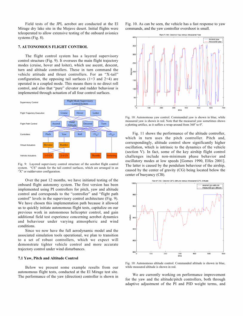
Below we present some example results from ourautonomous flight tests, conducted at the El Mirage test site.The performance of the yaw (direction) controller is shown in
Fig. 10. As can be seen, the vehicle has a fast response to yawcommands, and the yaw controller overshoot is small.
Fig. 10: Autonomous yaw control. Commanded yaw is shown in blue, whilemeasured yaw is shown in red. Note that the measured yaw sometimes showsa plotting artifice, as it suffers a wrap-around from 360o to 0o.
Fig. 11 shows the performance of the altitude controller,which in turn uses the pitch controller. Pitch and,correspondingly, altitude control show significantly higheroscillation, which is intrinsic to the dynamics of the vehicle(section V). In fact, some of the key airship flight controlchallenges include non-minimum phase behavior andoscillatory modes at low speeds [Gomes 1990, Elfes 2001].The latter is caused by the pendulum behaviour of the airship,caused by the center of gravity (CG) being located below thecenter of buoyancy (CB).
Fig. 10: Autonomous altitude control. Commanded altitude is shown in blue,while measured altitude is shown in red.
We are currently working on performance improvementfor the yaw and the altitude/pitch controllers, both throughadaptive adjustment of the PI and PID weight terms, and

through the incorporation of a pitch rate controller, which canbe used to actively control and reduce the oscillatory pitchbehaviour of the aerobot.
7.2 Waypoint Flight Control
At the flight trajectory execution control level in thesupervisory control architecture (Fig. 9), we haveimplemented a waypoint flight control system. Waypoints arespecified by the operator, who also sets the satisficingconditions that define when a waypoint has been consideredreached. The approach used is called “orienteering”, where thecontrol objective is defined in terms of reaching the waypoint,rather than in terms of the deviation from a given trajectory.Figs. 11 – 13 show autonomous waypoint flight control tests,again conducted at El Mirage.
Fig. 11: Waypoint flight control. Three waypoints have been reached, with anoperator-defined threshold of 25m to the GPS coordinates of the target.
Fig. 11 shows waypoint flight control for a sequence of 3waypoints. A waypoint is specified as having been reached ifthe aerobot is within an Euclidean distance of 25m from theGPS waypoint coordinates. A more complex test is shown inFig. 12, where a total of 6 waypoints are visited. Atmosphericconditions for both flights were moderate, with winds speedsbelow 5 knots. Finally, Fig. 13 shows an autonomous flighttest under substantial wind conditions, with gusts up to 10knots. The airship is blown off the direct waypoint route onseveral occasions when it is in a beam reach (orthogonal)condition relative to the wind direction. Additionally, it isoccasionally yawed off course when heading into or crossingthe wind. Nevertheless, the autonomous flight control systemwas able, even under these severe wind disturbances, to visitall waypoints. We plan to address wind disturbances explicitlythrough the incorporation of an H• robust controller design[Elfes 2001].
Fig. 12: Waypoint flight control. A total of 6 waypoints have been visited.
Fig. 13: Waypoint flight control under severe wind disturbances. Allwaypoints were reached.
Pose (position and orientation in 6 DOF) and motionestimation is currently done by fusion of IMU and GPS datausing a Kalman filter, allowing assessment of the vehicleflight control and trajectory following accuracy. To achieveglobal and regional localization on Titan in a GPS-independent manner, we are both investigating a celestialbody tracker for ephemerides-based global position estimates,and developing an image-based motion estimation (IBME)system with an associated multi-sensor state estimation filterthat will be used to fuse inertial and visual navigationestimates [Roumeliotis 2002].
8. CONCLUSIONS
LTA systems are a strategic platform the exploration ofplanets and moons with an atmosphere, such as Venus, Marsand Titan. Aerobots, in particular, can provide geographically

extensive science data at high resolutions and over variedterrains to a degree that cannot be matched by surface-boundrovers or other aerial vehicles. At the same time, operation ofan aerobot at Titan or other destination in the solar systemimposes significant long-term autonomy requirements.
The core autonomy technology needed for an aerobotmission elsewhere in the solar system is highly autonomousand robust flight control under little-known conditions. Weoutlined above a architecture for a substantially autonomousaerobot, described the current JPL aerobot testbed, anddiscussed initial steps towards the development of an aerobotflight control systems. This includes a new nonlinear roboticairship (aerobot) model intended for control system design andevaluation. The model brings together much of the airshipmodeling results published in the literature, and adds newfeatures to extend the model’s range of applicability. Themodel has been implemented, can be used to investigate allfour modes of flight (launch, cruise, hover, landing) and isparametrically defined for easy design configuration.
Our next steps include improving the flight control systemrobustness and accuracy, developing a trajectory followingsystem for systematic surveys, and incorporating vision-basedlocalization and navigation capabilities.
ACKNOWLEDGMENTS
The authors would like to acknowledge the help and supportof Eric A. Kulczycki, who was instrumental in aerobotpropulsion and flight testing, and Lee Magnone and MichaelS. Garrett, for support in avionics system development andfield testing. The research described in this paper wasperformed at the Jet Propulsion Laboratory, CaliforniaInstitute of Technology, under a contract with the NationalAeronautics and Space Administration (NASA), andadministered through the Intelligent Systems (IS) Program.The views and conclusions contained in this document arethose of the authors and should not be interpreted asrepresenting the official policies, either expressed or implied,of the sponsoring organizations.
REFERENCES
[Balaram 2002] J. Balaram et al. "DSENDS - A High-FidelityDynamics and Spacecraft Simulator for Entry, Descent andSurface Landing", IEEE 2002 Aerospace Conf., Big Sky,Montana, March 2002.
[Biesiadecki 1997] J. Biesiadecki, A. Jain, M. L. James. “AdvancedSimulation Environment for Autonomous Spacecraft”, inInternational Symposium on Artificial Intelligence, Robotics andAutomation in Space (i-SAIRAS'97), Tokyo, Japan, July 1997.
[Boschma 1993] J. H. Boschma. “The Development Progress of theU.S. Army’s SAA LITE Unmanned Airship”. In Proceedings ofthe AIAA Lighter-than-Air Systems Technology Conference,AIAA, September 1993.
[Chyba 1999] C. Chyba et al, “Report of the Pre-biotic Chemistry inthe Solar System Campaign Science Working Group”, TechnicalReport, JPL, 1999.
[Elfes 2001] A. Elfes et al. “Perception, Modelling and Control for anAutonomous Robotic Airship”. In H. I. Christensen, G. D.
Hager (eds.), Sensor Based Intelligent Robots, Springer-Verlag,Berlin, 2001.
[Elfes 2003] A. Elfes et al. “Robotic Airships for Exploration ofPlanetary Bodies with an Atmosphere: Autonomy Challenges”.Journal of Autonomous Robots, v. 14, n. 2/3. Kluwer AcademicPublishers, The Netherlands, 2003.
[Elfes 2004] A. Elfes, J. L. Hall, J. F. Montgomery, C. F. Bergh andB. A. Dudik. Towards a Substantially Autonomous Aerobot forExploration of Titan. In Proceedings of the InternationalConference on Robotics and Automation (ICRA 2004), IEEE,Las Vegas, May 2004.
[Foster 2003] N. Foster. Airspeed Airships.http://www.airspeedairships.com, 2003.
[Gomes 1990] S. B. V. Gomes. “An Investigation of the FlightDynamics of Airships with Application to the YEZ-2A. PhDthesis, College of Aeronautics, Cranfield University, 1990.
[Hall 2002a] J. L. Hall, V. V. Kerzhanovich, J. A. Jones, J. A. Cutts,A. A. Yavrouian, A. Colozza, R. D. Lorenz. “Titan AirshipExplorer”, in Proceedings of the 2002 IEEE AerospaceConference, IEEE, Big Sky, MT, March 2002.
[Hall 2002b] J. L. Hall, A. Elfes, T. Spilker, V. Kerzhanovich, J. F.Montgomery. “Titan Aerobots: An Overview of MissionScenarios and Required Autonomy Technologies”. Whitepaper,JPL 2002.
[Hall 2004] J. L. Hall, V. V. Kerzhanovich, A. H. Yavrouian, J. A.Jones, C.V. White, B. A. Dudik, G. A. Plett, J. Mennella and A.Elfes (2004). “An Aerobot For Global In Situ Exploration ofTitan”, 35th COSPAR Scientific Assembly, Paris, France, July20-24, 2004.
[Kerzhanovich 2002] V. V. Kerzhanovich, J. A. Cutts, H. W.Cooper, J. L. Hall et al. “Breakthrough in Mars BalloonTechnology”, in Proceedings of the World Space Congress /34th Scientific Assembly of the Committee on Space Research(COSPAR), Houston, TX, USA, October, 2002.
[Kröplin 2002] B. Kröplin. “Solar Airship LOTTE”. TechnicalReport, Institute for Statics and Dynamics of AerospaceStructures, University of Stuttgart, Germany, 2002.
[Lorenz 2000] R. D. Lorenz. “Post-Cassini Exploration of Titan:Science Rationale and Mission Concepts”. In Journal of theBritish Interplanetary Society, vol. 53, UK, 2000.
[NASA 2003] Solar System Exploration.http://spacescience.nasa.gov/admin/divisions/se/SSE_Roadmap.pdf.
[Payne 2004] J. Payne, S. S. Joshi. “6 Degree-of-Freedom Non-Linear Robotic Airship Model for Autonomous Control”.Robotics, Autonomous Systems, and Controls Laboratory(RASCAL) Technical Report 040521, University of California,Davis, 21 May 2004.
[Roumeliotis 2002] S. I. Roumeliotis, A. E. Johnson, and J. F.Montgomery. “Augmenting Inertial Navigation with Image-Based Motion Estimation”. In Proceedings of the 2002 IEEEInternational Conference on Robotics and Automation,Washington, DC, 2002.
[VEGA 1985] “Venus VEGA Mission Detailed Description”,http://robotics.jpl.nasa.gov/tasks/aerobot/studies/vega_detail.html.