automation of integration tests - personliga hemsidor på...
TRANSCRIPT

Master’s Thesis
Automation of Integration Tests
by Mikael Adenmark
Södertälje February 2003
Royal Institute of Technology (KTH) Department for Signals, Sensors and Systems (S3)
Supervisor KTH: Karl Henrik Johansson Supervisor Scania CV AB: Robert Sjödin

2

3
Abstract This master’s thesis project concerns integration tests of the future Scania truck in a lab environment. These tests are performed to verify the communication between the Electronic Control Units (ECU) connected to the Controller Area Network (CAN) of the truck. There are more than twenty different ECUs that work together in different ways by exchanging information over CAN. The tests are performed continuously during the development process of all new ECU software. The purpose of the project is to study some of the tests performed in the integration lab at Scania. These tests are then to be automated as far as possible, in order to save time when testing. There are different tests that are automated, of varying complexity. Some tests require external sensor signals to stimulate a response from the ECUs. So far this has been done manually by using function generators or knobs and switches connected to the ECUs. Much of this is therefore replaced by other tools, controlled from the lab computer. The project has resulted in a program, which includes a few automatic tests. These scripts perform the required stimuli for each test and then read the responses of this from the CAN buses. The results are presented in test protocols. The program is made easy to expand, as more tests are automated in the future.

4
5
Preface This master’s thesis project was performed at Scania in Södertälje, Sweden, at the RESA group, or the “Vehicle Electrical Architecture and Chassis System Software” group. The thesis is my final project before receiving my Master of Science degree in electronics at the Royal Institute of Technology, KTH. The report is written intended for both people at KTH and at Scania. I would like to thank my supervisor at Scania, Robert Sjödin, for all support with the integration tests. I would also like to thank Peter Madsen, group manager at RESA, for offering me the project and Karl-Henrik Johansson, my supervisor at KTH.

6

7
Table of Contents
1 Introduction ........................................................................................................................ 9
1.1 Outline...................................................................................................................................... 9
1.2 Problem Formulation.............................................................................................................. 9
1.3 Background............................................................................................................................ 10
2 Controller Area Network .................................................................................................. 11
2.1 CAN Protocol......................................................................................................................... 11
2.2 Scania Truck’s CAN ............................................................................................................. 12
2.3 ECUs of the Scania Truck .................................................................................................... 13
3 Brake Management .......................................................................................................... 15
3.1 Brake Management System.................................................................................................. 15
3.2 Auxiliary Brakes.................................................................................................................... 15
3.3 User Functions....................................................................................................................... 16
4 Integration Tests ............................................................................................................... 21
4.1 Integration Lab...................................................................................................................... 21
4.2 What Precedes the Integration Tests?................................................................................. 22
4.3 CAN Communication Test ................................................................................................... 22
4.4 Robustness of CAN Communication Test........................................................................... 23
4.5 User Function Tests............................................................................................................... 24
4.6 What Follows the Integration Tests?................................................................................... 25
5 Automating Integration Tests........................................................................................... 27
5.1 Identifying the Problems and Possibilities .......................................................................... 27
5.2 Main Program ....................................................................................................................... 29
5.3 CAN Communication............................................................................................................ 29
5.4 Robustness Tests.................................................................................................................... 30
5.5 User Functions....................................................................................................................... 31
6 Results ............................................................................................................................... 35
6.1 Automated Test Programs.................................................................................................... 35
6.2 Choice of Used Tools ............................................................................................................. 36
6.3 Future Automation Possibilities........................................................................................... 37
7 Conclusions....................................................................................................................... 39
8 Abbreviations .................................................................................................................... 41
9 References ......................................................................................................................... 43
10 Appendix ........................................................................................................................ 45

8
9
1 Introduction This master’s thesis project report includes the complete automation procedure of the integration tests concerned. It is shown how to create an automated test, what to consider and how available tools may be used and different tests may be structured. Since many tools are mentioned and how they may be used, the report could also serve as an inspiration source in other applications. However, the most effort is put on the specific task of this project. 1.1 Outline To receive an overview of the problems of this project, the surrounding environment is first discussed. This is done by describing the Controller Area Network (CAN) in chapter 2. CAN is the protocol used for communication between the Electronic Control Units (ECU) of the truck. Since much of the automation work involves the Brake Management System (BMS), this is discussed in chapter 3. This gives the reader better understanding of what is to be automated. Chapter 4 describes the integration tests as they are performed at the initialisation of this project. The chapter also describes what integration tests are, what is of interest of testing, what equipment is used etc. The actual automation work is discussed in chapter 0. This chapter is built up similar to the previous, by first discussing the problem in general, and then go deeper into each individual integration test. Chapter 6 brings up the results of the automation work, describing how the programs work on a high level, and also mentioning their performance. In chapter 7, finally the conclusions are drawn. The following chapters contain abbreviations, references and an appendix summary. 1.2 Problem Formulation The purpose of the project is to choose automation tools and automate some of the tests performed in the integration lab at Scania. Which tests to automate are selected together with Robert Sjödin, supervisor at Scania. The goal is to create a program that performs the selected integration tests automatically, and show that it is possible. A goal is that the following criteria should be met:
• Program performs test stimuli using necessary tools • Responses of the stimuli are verified by registering CAN traffic • Test results are generated automatically into a test template • Structure of the program makes it possible to add additional automated tests in the
future.
10
1.3 Background The future Scania truck uses a Controller Area Network (CAN), consisting of three CAN buses, to communicate between the different Electronic Control Units (ECU) of the truck. There are more than twenty ECUs available. Each ECU developer or function owner programs his software to agree with specifications. However, since most ECUs also communicate with other ECUs, they need to be tested together. They have to be “integration tested”. To do this Scania uses an integration lab, where all available ECUs are present and connected to CAN as in the future truck. The tests are performed in periods. Before each test period each ECU developer upgrades his software to add new features or to correct errors discovered in most recent specifications. The integration tests however take a lot of time to perform. In each test period all messages have to be identified on correct CAN bus, the ECUs have to go through a series of robustness tests and all user functions are to be tested. Often there is not enough time to perform all tests. This is why Scania has initiated this master’s thesis project.

11
2 Controller Area Network CAN stands for Controller Area Network and is used mainly in automotive industry, where the electric systems are growing more complex. CAN supports communication between Electronic Control Units (ECU) included in the network, linking the different systems to each other. An example of how a controller area network in a vehicle may be built-up is illustrated in Figure 1. In the future Scania truck CAN consists of more than twenty different nodes, from critical systems as the brake management system and engine to the audio system and information platform, distributed over three CAN buses. The buses are connected through a coordinator. Scania truck’s CAN is illustrated in Figure 3.
Figure 1. Example of a controller area network
2.1 CAN Protocol The CAN protocol is an ISO standard (ISO 11898) for serial data communication [1] which is mostly used by automotive industry. Other industries using the protocol are medical and railway industry. The protocol was initiated in 1983 by Bosch and was officially introduced in 1986. In 1993 the ISO standard was published [2]. CAN is based on so-called broadcast type of communication. This means that all nodes on the CAN bus will pick up all traffic on the bus. The received messages are all received differently though, depending on what information is of interest for that specific node. This is specified in the software of the control unit. The CAN protocol is message oriented, which means that messages are specified, each with its unique ID, instead of specifying nodes and their addresses. This makes it is easy to add or remove nodes. CAN messages do not contain any actual address information. Instead they can be said to be “contents addressed”, which means that their contents determines its address. Uninteresting information to a node is overlooked without any actions made, while interesting information is treated as specified in the software. For example, the engine would not react on a message carrying information about the volume of the audio system, but would on a message carrying information of the status of the accelerator pedal. However, the message’s source address, i.e. the transmitting ECU’s address, is always sent as a part of its ID.
ECU C1 ECU C2 ECU C3
COO
ECU B1
ECU B2
ECU B3
ECU A1 ECU A2
Bus A
Bus B
Bus C

12
ECUs transmit messages continuously with different intervals depending on the message’s importance and need of fast responses. If the need for a fast response is lesser, a longer transmission interval is used so that the bus is not occupied unnecessarily. The interval time can vary, for example if a parameter suddenly is changed this might result in a shorter interval time, when circumstances require this. Some messages are sent only on request from other ECUs or on change of state in some parameters. Message interval times are determined by specifications and implemented in the transmitting ECU’s software. Interval time varies between 10 ms and 10 s. There are four different message types or frames specified by the CAN protocol, where the data frame is one. This frame is built-up by various information. General bit distribution is illustrated in Figure 2.
Figure 2. Data frame message
The arbitration field contains information of the message’s priority on the CAN bus, which is used in case two or more messages are sent at the same time. The message with the highest priority is sent on the bus, while the less priorited message has to wait its turn to be transmitted. It also works as an identifier, and is used by the controllers to filter the messages. Scania uses CAN 2.0B with an arbitration field of 29 bits. The data field contains zero to eight bytes of data, i.e. up to 64 bits. Content of this field is set by the transmitting ECU, though its inner set-up is predefined. Signals in the data field remain the same, i.e. the bit distribution over the data field is constant, but its values may change. For example in a message, with a data field of eight bytes, sent by the instrument panel, one specific byte and two specific bits may contain information whether a button is pressed or not. 00 could for instance mean “button not pressed” and 01 “button pressed”. 10 and 11 could tell if the button was not available or that there was an error of some kind. The other message fields are used for error check and acknowledgement of correctly received message. In the forthcoming text, where “CAN message” or just “message” is written, the data frame is what is meant, unless otherwise is written. The three other message types are the remote frame, the error frame and the overload frame, all used for different purposes on the CAN bus. 2.2 Scania Truck’s CAN Scania uses a network consisting of three CAN buses, connected through a coordinator as illustrated in Figure 3 below. The ECUs are distributed over the three CAN buses. The red bus is considered the most critical and uses a minimum number of ECUs, including only driveline systems as the brake and engine management systems. This to protect these systems from less important systems who might cause failure on the bus [3]. This way the truck may function without danger to the driver even if the yellow and green bus would fail. Other important systems as the Instrument Cluster (ICL), who are not driveline systems, are connected to the yellow bus. The green bus contains all other less critical control units as the Audio System
13
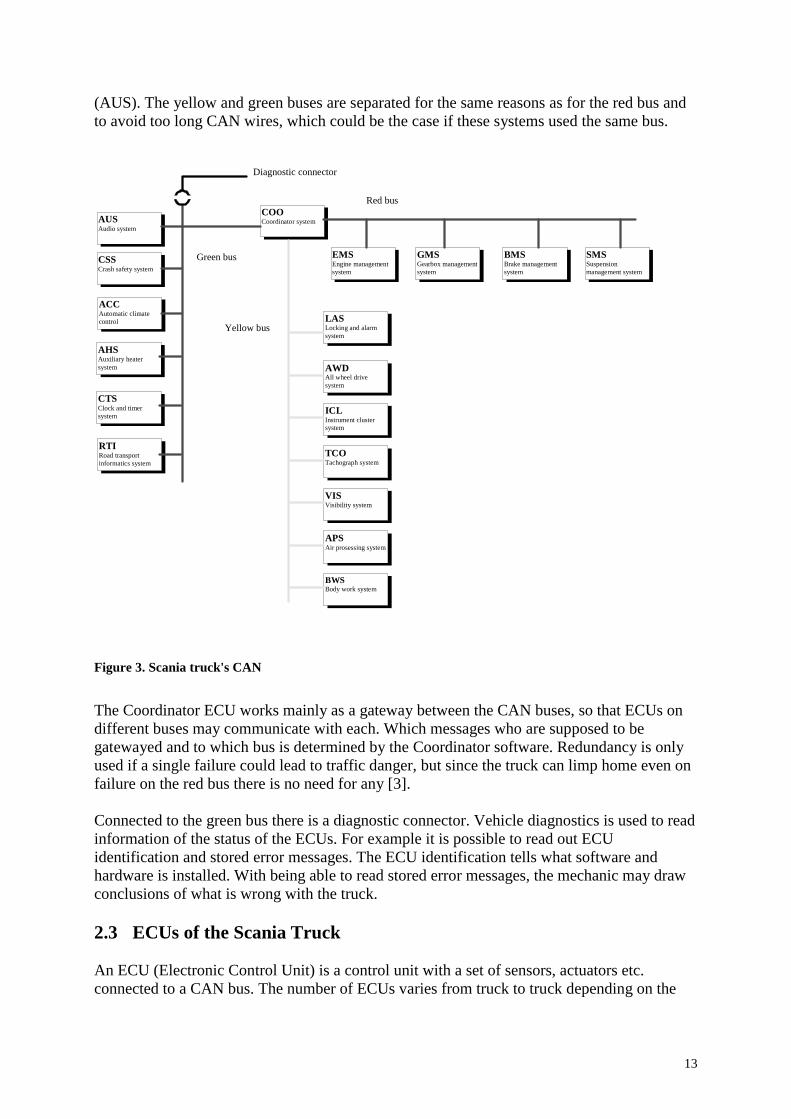
(AUS). The yellow and green buses are separated for the same reasons as for the red bus and to avoid too long CAN wires, which could be the case if these systems used the same bus.
AUS
Audio system
ACC Automatic climate control
AHS Auxiliary heater system
CTS Clock and timer system
CSS
Crash safety system BMS
Brake management system
GMS Gearbox management system
EMS Engine management system
COO Coordinator system
BWS Body work system
APS
Air prosessing system
VIS Visibility system
TCO Tachograph system
ICL Instrument cluster system
AWD All wheel drive system
LAS Locking and alarm system
SMS Suspension management system
RTI Road transport informatics system
Red bus
Green bus
Yellow bus
Diagnostic connector
Figure 3. Scania truck's CAN
The Coordinator ECU works mainly as a gateway between the CAN buses, so that ECUs on different buses may communicate with each. Which messages who are supposed to be gatewayed and to which bus is determined by the Coordinator software. Redundancy is only used if a single failure could lead to traffic danger, but since the truck can limp home even on failure on the red bus there is no need for any [3]. Connected to the green bus there is a diagnostic connector. Vehicle diagnostics is used to read information of the status of the ECUs. For example it is possible to read out ECU identification and stored error messages. The ECU identification tells what software and hardware is installed. With being able to read stored error messages, the mechanic may draw conclusions of what is wrong with the truck. 2.3 ECUs of the Scania Truck An ECU (Electronic Control Unit) is a control unit with a set of sensors, actuators etc. connected to a CAN bus. The number of ECUs varies from truck to truck depending on the
14
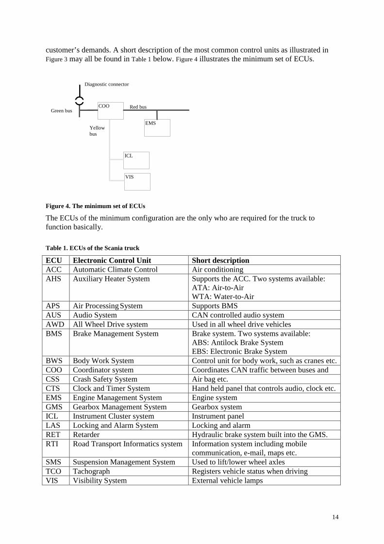
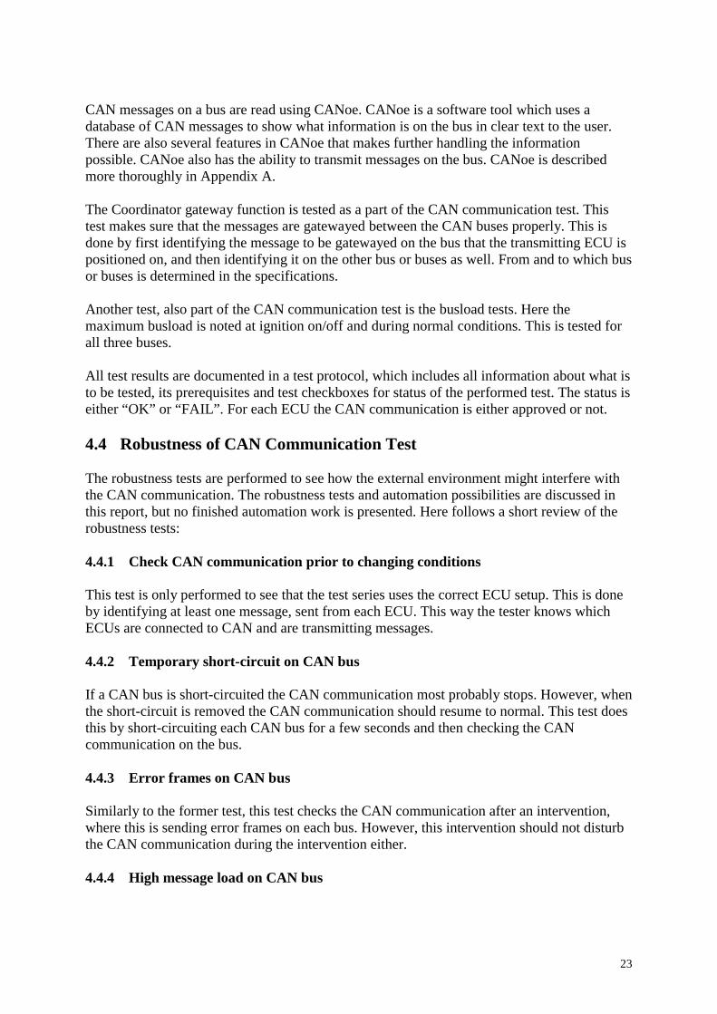
customer’s demands. A short description of the most common control units as illustrated in Figure 3 may all be found in Table 1 below. Figure 4 illustrates the minimum set of ECUs.
COO
ICL
VIS
EMS
Green bus
Diagnostic connector
Yellowbus
Red bus
Figure 4. The minimum set of ECUs
The ECUs of the minimum configuration are the only who are required for the truck to function basically.
Table 1. ECUs of the Scania truck
ECU Electronic Control Unit Short description ACC Automatic Climate Control Air conditioning AHS Auxiliary Heater System Supports the ACC. Two systems available:
ATA: Air-to-Air WTA: Water-to-Air
APS Air Processing System Supports BMS AUS Audio System CAN controlled audio system AWD All Wheel Drive system Used in all wheel drive vehicles BMS Brake Management System Brake system. Two systems available:
ABS: Antilock Brake System EBS: Electronic Brake System
BWS Body Work System Control unit for body work, such as cranes etc. COO Coordinator system Coordinates CAN traffic between buses and CSS Crash Safety System Air bag etc. CTS Clock and Timer System Hand held panel that controls audio, clock etc. EMS Engine Management System Engine system GMS Gearbox Management System Gearbox system ICL Instrument Cluster system Instrument panel LAS Locking and Alarm System Locking and alarm RET Retarder Hydraulic brake system built into the GMS. RTI Road Transport Informatics system Information system including mobile
communication, e-mail, maps etc. SMS Suspension Management System Used to lift/lower wheel axles TCO Tachograph Registers vehicle status when driving VIS Visibility System External vehicle lamps

15
3 Brake Management The future Scania truck supports hundreds of User Functions (UF), who all have to be integration tested. Automating all of these tests would take a substantial lot of time. Therefore the automation work in this master’s thesis project is limited to some brake related functions. In this chapter, the Brake Management System (BMS) and the UFs to be automated are described in order to get better understanding of what has to be done. 3.1 Brake Management System ABS Basic, where ABS stands for Antilock Brake System, and EBS, Electronic Brake System, are two different Brake Management Systems (BMS), where the EBS is the latest being developed at Scania. The BMS ECU includes in both cases a set of several brake functions that communicate with several different ECUs. One function is the “service brake”, which is the normal brake function, i.e. the retardation which is activated on demand from the brake pedal. The position of the brake pedal sets the level of retardation. The service brake function also calls the auxiliary brakes described in 3.2 for retardation if present and activated. Both ABS Basic and EBS include the service brake. ABS Basic includes not only the antilock function as the name implies, but also other UFs. The antilock function and Traction Control (TC) are the functions included in this project and are described below. EBS includes most functions that are included in the ABS Basic, but also includes some additional UFs, as rollover prevention and yaw control. These are however not mentioned here. TC and the antilock function are accordingly included in both ABS Basic and EBS. 3.2 Auxiliary Brakes Auxiliary brakes are used to reduce wear on the wheel brakes. The auxiliary brakes are the retarder and the exhaust brake. These are described shortly below. 3.2.1 Retarder The Scania retarder is a hydraulic brake connected to the gearbox. The retarder ECU controls the cut off of oil to the outgoing axle of the gearbox and delivers brake torque with the increased friction under development of heat. The retarder may be applied by a lever, where its position determines the requested brake torque. It can also be activated on request from the BMS, if the retarder switch on the instrument panel is set to “automatic”. A telltale then shows if the retarder is active. The retarder is most effective at higher speeds and effectively used in downhill. 3.2.2 Exhaust brake The exhaust brake is another brake function, which is built into the EMS and is not an own control unit. The exhaust brake uses engine friction to reduce vehicle speed. This is done by reducing the exhaust flow from the engine. The exhaust brake is activated automatically on brake request. In some trucks the exhaust brake may be applied manually.

16
3.3 User Functions There are three different types of User Functions (UF), who are defined differently depending on their use of the CAN buses. First there is DECs (Discrete Electric Circuit), who are either not ECUs or ECUs not connected to a CAN bus. Then there are SIFs (System Internal Function) that are UFs implemented in an ECU but do not require any CAN information. Finally there are the DFs (Distributed Function), who are implemented in several systems. The UFs in this project are of the later type. An ECU’s UFs are implemented in the software of the ECU. UFs vary in complexity, where more complex functions involve several ECUs, communicating with each other over CAN. The UFs are described in Message Sequence Charts (MSC), who illustrate the CAN communication between the ECUs and the driver environment. These are read downwards, to get the correct chronological order. UFs are also described in System Descriptions (SD) and User Function Specifications (UFS) in plain text to get better understanding of how they are supposed to work. The two UFs mentioned here are Traction Control (TC) and Antilock Wheelbrake Control. These functions are installed in the BMS software and use wheel speed sensor signals as input. There is one sensor for each wheel, continuously registering wheel speed. The front axle speed is calculated as the average of the two front wheels. The front axle speed and the speeds for each wheel relative to this are gathered in the “EBC2WheelSpeedProprietary” CAN message, which is sent from the BMS. The relative speeds are calculated before sent with the message and have a span of +/- 7.8125 km/h and a resolution of 1/16 km/h/bit using one byte each. The front axle speed spans from 0-251 km/h with a resolution of 1/16 km/h/bit using 2 bytes of data. 3.3.1 Traction Control Traction Control (TC) is a function, which is used to prevent wheels from spinning due to high engine torque. There are two cases: When one drive wheel is spinning and when both drive wheels are. These cases activate brake control and engine control respectively who are two different control loops. TC is not available on all wheel driven trucks [7]. By pressing the “TC Off” button on the instrument panel the allowed slip is increased.
Brake control is activated when one drive wheel is spinning. When this is the case the wheel brake is applied on the spinning wheel to achieve the same speed on both drive wheels. Brake control is only activated at low vehicle speeds i.e. low front axle speeds. The MSC for brake control is illustrated below, followed by a short description.
3.3.1.1 Brake control

17
BMS COOEnv. ICL
One drivingwheel isspinning A
Wheel SpeedSensors
D
EBC1-A(ASR Brake Control =
ASR brake control active)
TelltaleTC-Active
Engage brake onspinning wheel
CEBC1-A
(ASR Brake Control =ASR brake control active)
GMS(OPC)
B
A: Traction Control B: Automatic mode – Calculation of new gear C: Gateway D: Telltale – TC-Active
Figure 1. MSC for TC: Brake control
The BMS initiates the brake control when the wheel sensors give information that one drive wheel is spinning. Brake control is activated when the wheel slip between the drive wheels is 12 km/h. The sensors are connected to the BMS, so when the spinning on one drive wheel is registered, i.e. this wheel rotates faster than the other drive wheel, the BMS immediately applies brake pressure on this wheel and sends the “EBC1-A” message on the CAN bus with the signal “ASRBrakeControlActive”. The message is received by the GMS and gatewayed through the COO to the ICL. The instrument panel then displays the TC-Active lamp to the driver. The GMS uses this information for calculation of a new gear if using automatic gear. Brake control ceases when the spinning wheel has the same speed as the other drive wheel.
Engine control is activated when both drive wheels are spinning. Instead of braking the wheels, the engine torque is reduced to make the spinning cease. The target of the control loop is to reduce the relative speed difference, between the spinning wheels and the front axle speed, down to an average slip of 3.0 km/h. The control loop is adaptive however, increasing the target slip when the accelerator pedal is depressed [8]. Engine control can only be engaged at low speeds. The MSC for engine control is illustrated below, followed by a short description.
3.3.1.2 Engine control

18
BMS COOEnv. ICL EMS
Both drivingwheels (on oneaxle) is spinning
Wheel SpeedSensors
EBC1-A(ASR Engine Control Active =
ASR engine control active)
TelltaleTC-Active
TSC1-AE(Override Control Mode = Speed/Torque Limit Control,
Override Control Mode Priority = Medium Priority,Requested Torque = X%)
C
Reduce engine torque
EBC1-A(ASR Engine Control Active =
ASR engine control active)
A
D
E
GMS(OPC)
B
A: Traction Control B: Automatic mode – Calculation of new gear C: Commanded Torque Limit D: Gateway E: Telltale – TC-Active
Figure 2. MSC for TC: Engine control
The BMS initiates the engine control when it registers spinning drive wheels from the wheel speed sensors. It immediately sends the “TSC1-AE” message on the CAN bus, which is received by the EMS. The “TSC1-AE” message contains information according to the MSC. The “RequestedTorque” signal decreases from previous TSC1-messages. As a respond to this the engine decreases the engine torque. The BMS also sends the “EBC1-A” message with the signal “ASREngineControlActive” to the GMS and to the ICL gatewayed through the COO. The TC-lamp is lit on the instrument panel. The GMS uses the information to calculate a new gear. The engine control ceases when the target slip is reached. Then the TSC1- and EBC1-A messages return to their previous signal values. 3.3.2 Antilock Wheelbrake Control The Antilock Wheelbrake Control (ABS) is used to prevent wheels from locking during braking. This maximises vehicle stability and reduces wear on the tyres using maximum available friction. Disengaging brake torque from the Retarder and Exhaust Brake and reducing brake torque on the wheel brakes does this. The MSC for ABS is illustrated below, followed by a short description.

19
EBS/ABS OPT/GAEDCRETI/O
A
Wheel locking
B
C
EBC1-A: Anti-lock Braking (ABS)Active: ABS active
TSC1-AREX: Override Control Mode: Speed/Torque Limit ControlTSC1-AREX: Override Control Mode Priority: Highest PriorityTSC1-AREX: Requested Torque: 7Dh (= 0%)
TSC1-ARD: Override Control Mode: Speed/Torque Limit ControlTSC1-ARD: Override Control Mode Priority: Highest PriorityTSC1-ARD: Requested Torque: 7Dh (= 0%)
D
AWD
E
TC1: Disengage diff.lock 2, central: Disengage differential lock
A. EBS 5, ABS Basic braking B. Retarder activation C. Exhaust brake activation D. Gear shift limitations E. AWD, Differential lock control
Figure 3. MSC for Antilock Wheelbrake Control
The wheel sensors register the wheel speed signals and the BMS registers if the wheels are locked. The BMS sends the CAN message “EBC1-A” with the signal information “ABSActive”, which is received by the gearbox, for calculation of a new gear. “TSC1-ARD” and “TSC1-AREX” are sent to the Retarder and EMS to cease retarder and exhaust braking respectively (Requested Torque = 0%). The auxiliary brakes should be deactivated within a specified time interval when the sensors register the slip [3].

20

21
4 Integration Tests Integration tests are performed to see how different individual systems work together. At Scania these tests are performed in the integration lab, where test series are performed about ten times each year. The individual systems include all ECUs of the truck. In this chapter the conducted tests are presented, to get a better overview of the integration tests. Also what is done between the test series is described in short. Worth mentioning is that the most effort in this master’s theses project has been put on the CAN communication test and parts of the User Function tests. The robustness tests have been looked at, but no more automation work has been done except making sure it is performable. Diagnostic tests are performed to verify the functionality of the vehicle diagnostic services. These are performed in the integration lab but are however not included in this project and therefore not mentioned further. 4.1 Integration Lab The integration lab is a medium size room, where a large rig takes most of the space. On the rig all the systems of the truck are placed, each on their own lab board, in most cases with the most recent software installed since this is what is of interest in being tested. Most systems also contain a test device of required sensors and switches to be able to test all functions of the ECU. All ECUs are connected to CAN as described in chapter 2.3. The rig also includes a panel with steering wheel, stick shift, buttons and all which could be added to the truck. Another large panel on the wall shows all extern lights. Switching the power on and turning the ignition key activates the rig. Normal voltage to the rig is 24 – 28 V as in the truck. This is supplied by a SM 44-70 D power supply from the Dutch company Delta Elektronika. This device is able to control the output voltage both by a knob manually or by a control voltage (0 - 5.16V) to the back of the device. However, the voltage is normally set to 24 V by the knob. To use the control voltage instead, a switch position has to be changed. This switch sits beside the control voltage input.
Figure 4. Integration lab
For monitoring and testing, the lab also contains two lab computers, where one is used mainly for developing and the other for testing. It is also easy to connect to the rig with a laptop, connecting easily to the CAN buses or to the diagnostics socket.

22
Test computer installed/connected hardware: • dSPACE PCMCIA card. The card is connected to a dSPACE set of hardware with the
computer. This includes four wheel speed signal generators, four PWM signal generators, two engine speed signal generators (sine waves)
• NI PCI-DIO-96. A 96-bit parallel, digital I/O interface for the PC. In the lab the card is used to send control voltages of 5V to the relays described below.
• NI PCI-6024E, low cost DAQ multifunction PCI-card. Contains two 12-bit analog outputs, 8 digital I/O lines, two 24-bit counters and up to 16 analog inputs. Used in the lab only to generate control voltages with the two analog output ports.
• Two LapCAN cards á two CAN channels. Used to communicate with the three CAN buses from the computer.
The development computer only uses one LapCAN with two channels to be able to communicate with CAN. It is easy though to switch between which two CAN buses to monitor. Each ECU has, on the same lab board, a box of three relays used to shut off its power supply, ground connection and CAN connection. The relays use a voltage of 5 V to switch off the connection. This control voltage is fetched from the NI PCI-DIO-96 board installed in the test computer. Part of his is the product of earlier automation work. More of this is described in chapter 5.3. 4.2 What Precedes the Integration Tests? Before each test round, the ECU developers have to make sure the latest software version is installed in the ECUs. They also have to make sure that the one conducting the integration tests is aware of this. The tester has to know which software is installed and how it differs from previous versions in order to be able to test correctly. Therefore, each test period is initialised by a meeting between tester and one responsible for each ECU. The tester notes all updates and with this information test protocols may have to be updated. 4.3 CAN Communication Test The CAN communication test is performed to see if the ECUs are sending CAN messages as specified. Each ECU is supposed to send a certain number of messages on the bus with specified intervals. A CAN message (data frame) is defined by its two-byte PGN number, i.e. four hex digits. This is defined in the database and is what has to be identified when testing the CAN communication. When a message with the correct PGN is identified, its source address and priority has to agree with the specifications. If this is not the case, the software is sending the message with wrong properties. The interval time between each transmitted message is also noted to agree with the specifications. In some cases messages are sent only at events, described in user function specifications or MSCs. These are normally identified first when the user function that the message is used in is tested, since they are not sent continuously. In these cases the ECU is provoked to send the message. If the tested ECU sends additional messages from what is specified this is noted as well. These tests are performed for all ECUs, where the CAN bus, which the ECU is positioned on, is scanned. The values of the message’s signals are however not noted here.
23
CAN messages on a bus are read using CANoe. CANoe is a software tool which uses a database of CAN messages to show what information is on the bus in clear text to the user. There are also several features in CANoe that makes further handling the information possible. CANoe also has the ability to transmit messages on the bus. CANoe is described more thoroughly in Appendix A. The Coordinator gateway function is tested as a part of the CAN communication test. This test makes sure that the messages are gatewayed between the CAN buses properly. This is done by first identifying the message to be gatewayed on the bus that the transmitting ECU is positioned on, and then identifying it on the other bus or buses as well. From and to which bus or buses is determined in the specifications. Another test, also part of the CAN communication test is the busload tests. Here the maximum busload is noted at ignition on/off and during normal conditions. This is tested for all three buses. All test results are documented in a test protocol, which includes all information about what is to be tested, its prerequisites and test checkboxes for status of the performed test. The status is either “OK” or “FAIL”. For each ECU the CAN communication is either approved or not. 4.4 Robustness of CAN Communication Test The robustness tests are performed to see how the external environment might interfere with the CAN communication. The robustness tests and automation possibilities are discussed in this report, but no finished automation work is presented. Here follows a short review of the robustness tests: 4.4.1 Check CAN communication prior to changing conditions This test is only performed to see that the test series uses the correct ECU setup. This is done by identifying at least one message, sent from each ECU. This way the tester knows which ECUs are connected to CAN and are transmitting messages. 4.4.2 Temporary short-circuit on CAN bus If a CAN bus is short-circuited the CAN communication most probably stops. However, when the short-circuit is removed the CAN communication should resume to normal. This test does this by short-circuiting each CAN bus for a few seconds and then checking the CAN communication on the bus. 4.4.3 Error frames on CAN bus Similarly to the former test, this test checks the CAN communication after an intervention, where this is sending error frames on each bus. However, this intervention should not disturb the CAN communication during the intervention either. 4.4.4 High message load on CAN bus

24
This robustness test checks if the ECUs retain proper CAN communication during high message load on the bus. This is done by, using CANoe, generating messages on the bus up to certain busloads, and see if the CAN communication remains properly. Communication with busloads up to 90% is verified. 4.4.5 Temporary open circuit on CAN bus This test works as the temporary short-circuit test does, but in this case instead of short-circuiting all ECUs on the bus are disconnected causing an open circuit on the bus. This should not have affected the CAN communication when the ECUs are reconnected. 4.4.6 Low voltage This test checks the CAN communication when the truck voltage is reduced. From 24 V the voltage is slowly reduced in stages down to 0 V. At which voltage the CAN communication stops is noted for each ECU. As the voltage is increased back to 24 V the voltage where the CAN communication starts again is noted. 4.4.7 High voltage This test is performed as the low voltage test, but instead increasing the voltage up to 35 V. 4.5 User Function Tests There are hundreds of user functions that all work differently. A user function can be as simple as a CAN message, which should be sent when a button is pressed. Or it can be more advanced as Traction Control, where several ECUs exchange information and work simultaneously. However, only two user functions are included here: Antilock Wheelbrake Control and Traction Control. In most cases there are some prerequisites for the function to be activated. For example a switch might have to be active or a sensor has to have some specific value. The prerequisites may be verified with CANoe. To activate the user function a “stimuli” is performed. This could be for example activating another switch or increasing/decreasing vehicle speed depending on the user function. The responses are validated with CANoe; by noting if a light is activated or whatever, depending on what the expected response is. The tester follows a test protocol of prerequisites, stimuli and expected responses going through all user functions. Traction Control (TC) and Antilock Wheelbrake Control as functions are described in chapter 3. Both these user functions are activated at certain wheel speed properties, determined in the ECU software. The wheel speed signals are generated from wheel sensors, on each wheel, connected to the BMS. To simulate vehicle speed in the test rig, therefore function generators may replace these sensors. This way the BMS is given the apprehension of a moving vehicle. In the case with TC, engine speed has to be simulated as well. This may, however be done by a +/- switch manually on the EMS board in the lab. In some cases speed to the Tachograph (TCO) is also needed for the function to be activated. This may be done from a small box on the TCO board. More about these prerequisites and stimuli are presented in chapter 5.5.

25
4.6 What Follows the Integration Tests? When all tests are performed, the test results are summarised and presented in a report, with all test protocols attached. The report is distributed to all ECU owners and function owners and other Scania people it concerns. With the integration lab test results, it is determined whether tests in truck can be allowed using the tested ECU software.

26
27
5 Automating Integration Tests Before you can do any automation work, you need to know exactly which tests are made and how they are performed. You have to know how the manual tests are performed and see which tools are used or if any automation work perhaps already has been made. This project has involved creating or updating existing test cases for the BMS. This has been done using MSCs, system descriptions and function descriptions. With this information all interesting signals may be added to the test case, both to make sure the functions work as supposed to, but also to give the tester a better overview of how the test has been performed by the computer. It is always better to include more information than required than the opposite. The BMS has been described in chapter 3. When this initiating work is done the work may begin by identifying the automation possibilities. This includes finding out what may be automated and which tools are available. When a set of tools are chosen, these also have to be able to communicate with each other in order to have a completely automatic test. If this was not possible, worked poorly or would mean an extensive effort relative to the benefit, you would have to decide whether a semiautomatic test should be considered instead. So far the work around an automation procedure has been presented. The manual tests have been described, and also what is tested and how things around it work. However, no actual automation work has been presented. This chapter will look into this, both describing how and why the approaches have been chosen and also go through how the automation program works. Appendix B describes the program additionally and is useful when editing the test program. 5.1 Identifying the Problems and Possibilities Most of the integration tests include scanning the CAN communication on the buses. To communicate with CAN and to visualise it to the user, CANoe is used in the integration lab. With the help of CAPL-programs, who are added to the CANoe configurations, it is easy to filter interesting messages and with the CANLIB library as COM interface CANoe may be accessed from other software. CANoe also uses tools as the database editor, which makes it easy to handle messages and use the environment variables. CANoe is described in Appendix A. With CANoe active during an automated test, you also get the bonus of having a better view of what is happening around what is actually being tested. This way a possible error could be detected, even when not looked for. Therefore it is a natural choice to continue using CANoe in the automation process where the information on the CAN busses needs to be logged. Among the possible COM servers to communicate with CANoe, Visual Basic is the most supported by Kvaser [1]. Short examples may also be found in the CANoe help. VB allows short developing time and is also a comfortable program to work with. This also makes it easier to edit other people’s code. This makes VB an interesting choice as main program. Visual Basic is described in short in Appendix A. In order to automate the test, the results have to be presented in some way. Before this master’s thesis project all results, presented in CANoe, were manually filled into an MS Word test protocol step-by-step. In an automated test however, you would want the program to do this automatically as well, especially if much information is to be presented. In this case, writing information to a test protocol would be of interest. In some cases one would also want to read information from the same protocol, if this protocol contained information of what to

28
test. This is difficult to do using Word. Useful when working with Excel instead is the Visual Basic editor, VBA, in which Excel macros are coded. This makes it easy to create VB-code just by recording a macro, which may speed up the developing time. All that can be done with Excel is also possible to do from VB. Excel is a good instrument to present results and tables as will be done in this test. Using Excel instead of Word also makes it easier to keep track of where to write the information thanks to its rows and columns. If both reading and writing information between Excel and Visual Basic were used, the tester would not have to type any results himself. In the integration lab there is a LabVIEW virtual instrument (VI) which, by clicking a button in the program window, disconnects an ECU’s power supply, ground- or CAN connection. LabVIEW is described in short in Appendix A. Most ECUs have their own box of three relays, each removing one connection to the control unit. This has been a part of previous automation work. Using the relays is useful when scanning the CAN communication, since some ECUs may send messages with the wrong source address or interfere in some way. However, to use the relay program it had to be remade to be able to add new relays to control. This was because of errors in the previous program. The principal remains the same though. To additionally automate the use of the relays, the VI would need to be able to be called from the main automation program. Visual Basic has an interface with LabVIEW, which makes it able to run VIs and call DLLs. The DLLs can be created from VIs in the LabVIEW Application Builder. This is further described in Appendix B. With this the main program would be able to disconnect ECUs, who might interfere with the test, and then reconnect them when they are of interest again, without the user having to do this manually. For the robustness tests, much may be done by using CANoe only. For example, to check the CAN communication during high busload it is easy to transmit messages with CANoe to achieve this. There are however, already a couple of written CANoe configurations and CAPL-programs to do this work. But much of this may be done automatically from a main program, which opens the correct configurations, runs the programs and also presents the results in an Excel template when finished. Some CAPL-programs will also have to be rewritten. To automate the two included User Function (UF) tests, wheel speed signals have to be sent to the Brake Management System (BMS). This is because these signals, received from wheel speed sensors, are control input for both control loops. Testing Traction Control also requires a wheel speed signal to the Tachograph (TCO) and an engine speed signal to the Engine Management System (EMS). Previously this has been done manually by using two function generators for wheel speed generation. This way two wheel speed signals always have to use the same signal. Between the tests, one has to change the wiring of the parallel connections and function generators. Using four generators, one for each wheel, would take too much time to do manually. Because of the properties of the BMS, it is easy to receive a non-valid wheel speed combination using the manual function generators. When this happens, the wheel speed CAN signal values (in the CAN message “EBC2 Proprietary”) are set to “error indication” instead of the actual speeds. To regain the correct signals, one has to alter the generators back-and-forth using valid combinations, including going back down to zero speed on all wheels. This may take a while. Therefore, one would want the signals to be generated more accurately and, to automate the test, use a function generator that may be controlled from a computer instead.

29
They also have to be able to be controlled from the main automation program in order to become completely automatic. This work is described more thoroughly in chapter 5.5. There is a small switch on the EMS lab board that increases or decreases the engine speed. This is done slowly, with very bad precision. To alter the TCO speed, there is a box on its lab board that does this using a knob with fixed positions. For a fully automated test of the UFs, one has to be able to generate these signals as well and control it from the lab computer and the main program. 5.2 Main Program When automating a wide range of different tests, it is important that you maintain an overview of how the test programs are connected. You have to consider the man-machine interaction for really making the automated test easier, faster and hopefully also more accurate. Using VB you have to decide whether all different test scripts should be added to the same project or if they should be run independently in different programs. Since only one form is run at a time, adding all tests to one main program does not affect performance. By using one program for all tests also decreases the required time. Therefore, before the final automation programs are collected, you have to create a base, which is to be followed in the future as more tests are automated and added to the original program. This base should make it easy for the user to perform the tests and also present the results automatically. Putting effort into creating a solid program base also makes the future automation work easier, especially as the program grows further. With its capabilities and since it is easy to use, Visual Basic makes a natural choice of main program. Even if, for instance Visual C++, might do the job as well, VB has the advantage of lesser development time and being easy to use. This is however, a matter of opinion. In this master’s thesis project, Visual Basic has meant much saved coding time. The VB Main Program is built up by several different forms. The user interface is one of them, but only works as a link to the other forms. This is to make it easier to get an overview over all available tests in the program. It also makes it easier to add more UF tests in the future. For example, by pressing the “Start CAN communication” button, the main form would still be the only visual form to the user, while the CAN communication form would be the one doing all the work on the computer. The user interface is described and illustrated additionally in Appendix B. 5.3 CAN Communication The CAN communication test is performed to see if CAN messages are sent as they are supposed to according to the specifications. Every ECU included in the test is scanned, to see that the ECU sends the specified messages and nothing else. Each message has an ID of eight hexadecimal digits, with different meaning: The first two digits tell the message’s priority on the CAN bus. The four middle digits form the Parameter Group Number, PGN, which is message specific. In some cases a message has a specific two-digit destination address. Then the two last digits of the PGN is equal to this destination address. The last two digits of the ID tell the message’s source address, i.e. which ECU the message is sent from. Both interval time and message ID is of interest in the CAN communication test.

30
In a manual test, the tester looks for the messages sent on the buses using CANoe. With filter panels, the trace window in CANoe may display only messages sent from a specific ECU or on a specific bus. The tester notes that the PGNs match those in the test protocol, that the source address and priority is correct and that the interval, with which the messages are sent, is close enough to what is specified. Since ECUs may send messages with the wrong source address, the LabVIEW relay application is used to disconnect possible interfering ECUs. When identified, the results are filled into a test protocol. Earlier it was mentioned that Visual Basic could be used as main program, to control both CANoe and LabVIEW generated DLLs, and how to both read and write to an Excel template. This makes it possible to create a program, which first reads information from an Excel test protocol. The program sends this information to CANoe that uses a CAPL-program to scan the wanted bus for the CAN message with the matching properties. When or if the message is identified, CANoe sends this information back to the test protocol via the main program. In Excel the results are evaluated automatically, by comparing the information sent from CANoe with the information that was first read. This procedure is looped, going through all messages for all ECUs. This way the program code will not have to be altered each time the specifications change. Instead, only the test protocol is changed to match the specifications and the program works as it always has. The procedure is illustrated in Figure 5.
Figure 5. CAN communication program
To get a more reliable test, the program also includes disconnecting possible interfering ECUs. For instance, in some truck configurations, the Coordinator may transmit CAN messages with a different source address than its own. For the sake of safety it is a good thing to disconnect all other ECUs. When disconnecting the ground- and/or supply-connection to some ECUs without removing the CAN connection, error frames may be sent on the bus disturbing the CAN communication. That is why it is better to remove the CAN connection to the ECUs. This way the ECU cannot disturb the other CAN traffic in this test, unless the tested ECU responds negatively to the lack of a disconnected ECU. In these cases this or these ECUs will have to remain connected to the bus. In Appendix B individual parts of the test program are described. 5.4 Robustness Tests There are several robustness tests performed to check how the CAN communication works during different kinds of stimulation. These are described in chapter 4.4. Some semiautomatic
31
tests have been created earlier, but these are easy to improve using the results from the work in this master’s thesis project. However, as mentioned earlier, not much new robustness automation work is included in this master’s thesis project. What is done is only to include the semiautomatic tests into the main program, with minor changes to fit the program frame and become better structured. With this structure, three CANoe configurations are sufficient for all robustness tests. This is done in order to make way for future completely automatic robustness tests. Some ideas of how to automate further are presented in Appendix B. In all cases it is possible to make a completely automated test, where an Excel test template is filled with the results automatically. The Excel template will use an own sheet for each robustness test, instead of lining them in a row in one sheet as in the test protocol in MS Word. This way the results become more easily overviewed. 5.5 User Functions As mentioned earlier, two UFs are included in this project. These two; Traction Control (TC) and Anti-lock Wheelbrake Control; both require wheel speed signals to be activated. There are four wheel speed sensors, one for each wheel, in the lab. TC also requires signals to the EMS and the TCO. The solution to this is presented below. Another task is to create the test case and perform this automatically in one program and present the results. A goal is to include all test cases in one program, and therefore it is optimal also to include the UF tests in the VB main program. The major difference from the other tests is the stimuli that are required for activation of the UFs. The solution to this is presented below. 5.5.1 Wheel speed generation With one function generator for each signal, six generators are required. If only two generators were used for the wheel speed signals and using one of these also to the TCO speed signal, this could be reduced to three function generators. This would however mean that one would have to redo the wiring between each test. There are several function generators on the market who can be controlled from a computer. Most of these use a GPIB interface with the computer. These require a GPIB card installed on the computer. There are also some PCI-card function generators who are installed in the computer. Some possible solutions are presented below. As a reference, some existing products are mentioned as examples of these solutions. The British company Thurlby Thandar Instruments Ltd provides self standing function generators with multiple outputs [9]. These are accessed via the GPIB-interface. There are LabWindows drivers to control the generators on the GPIB-bus. The price for a 4-channel function generator lies presently at € 4855 (September 2002). The LabWindows drivers can be accessed with ActiveX controls. From Visual Basic it is therefore possible to use ActiveX to control the LabWindows drivers. These in turn would then control the signal generation. Information of this may be found on http://www.ni.com. There is however limited slot space in the lab computer and adding the GPIB board and required software, as LabWindows, the price increases. Using ActiveX to communicate between LabWindows and VB is possible, but would mean a lot of effort. The time before all gear could be delivered is also considered, when going through other possibilities to generate computer controlled signals from the computer.

32
National Instruments provide several different PCI cards, with various sets of analog output (AO) ports. These can be used to generate waves with the help of LabVIEW. In LabVIEW a signal waveform of a chosen number of points is created. This is then looped and written to the AO ports of the PCI card. There are also Counter ports on several of these that can be used to generate waveforms. NI provides some example programs to use both the AO- and the Counter ports. An advantage using these would be that LabVIEW DLLs already are used in the CAN communication test, which was completed before this problem was considered. The technology is therefore already known, which could save time. On the lab computer the low-cost multifunction PCI-6024E board is installed. This includes two AO- and two Counter ports, where only the two AO ports are used in the supply test. However the board could be used as test board, to determine if the generated signals were of sufficient quality for wheel speed generation. Using examples supplied by NI, the signals could be generated, but with alterations required. For example, these can only use one port at a time. However, problems arise, using these examples. Using the Counter ports, the generated signals go down for a short period of time each time the input frequency is altered. This would give unlikely conditions to the BMS making the wheel speed CAN signals fail. Using the AO ports, the problem is using both AO ports simultaneous. This is solvable, but problems could arise if more than two channels are used. NI deliver PCI boards with eight output channels, which would be sufficient. One side effect with using the AO- or Counter ports is that this requires that the process is run on the lab computer. This would take processor power from the other programs running simultaneously in an automated test, especially the more signal ports are used. This could result in information being lost or time delays, causing program failure. Mentionable is also that the 6024E board could not be used for wheel speed generation on the lab computer, due to problems with its motherboard. The board could not be given an Interrupt Request (IRQ), and therefore the signal waveforms in LabVIEW could not be written to the board continuously as required for the VI to work. This however works on other computers. NI also delivers some PCI based function generators with application software aimed at Visual Basic. These, however only come with one channel output, requiring even more slots from the computer, as several function generators will be needed. Replacing the lab computer was never an issue, due to the lot of both hardware and software installed. In the integration lab there exists a box of hardware from dSPACE, which is used by a truck simulator, from a previous master’s thesis project. This truck model uses Simulink to implement a Modelica model into the hardware, using CAN messages as some of the inputs. This box has been used in some other UF tests, in order to receive adequate prerequisites. However, the box includes four wheel speed signal generators (sine waves) and four additional PWM signal generators. It also supplies engine torque signals. Therefore, if this could be used in an automated test, it would be the obvious choice of function generator. To access the real-time application in the dSPACE box there are the MLIB, CLIB and RTPLib libraries. Due to licence limitations, however, it has only been possible to use the MLIB in this project, even though the licence could be increased to include the other libraries as well if required. Matlab will also have to be used in all cases, in order to implement the

33
application into the hardware. The hardware is therefore chosen to be accessed through the MLIB, with Matlab as a COM-server. To access the hardware, a Simulink model has to be created, using dSPACE’s Simulink blocks. To control the input of the Simulink model, constants are added. Given names instead of numbers, these constants are added as “Tuneable Parameters” in the Real-Time Workshop (RTW) of Simulink. When building the RTW, the Simulink model is implemented in the hardware. The tuneable parameters are then used to vary the output signals from the hardware. The parameters have to be altered in Matlab, with commands defined in the MLIB. For example, to change the tuneable parameter “wheelspeed1” to 50 km/h, you would write mlib(‘write’, data, ‘wheelspeed1’,50) in the Matlab window. All commands can be viewed in the Matlab help, by typing >>help mlib To use this from the Visual Basic main automation program, the command Matlab.Execute(“”) is used. Within the parentheses, the Matlab command is written. This however requires that Matlab is first opened and initialised from VB. With the CLIB it would be possible to do this without running any other program. In this case, a C-DLL could be built and called directly from the VB-program. In both cases however, the Simulink model has to be built in RTW once before use, which is done via Matlab. With the RTPLib, Python scripts would be required and would be run from for example PythonWin and would therefore not be a better solution. To visualise the current signal values, Controldesk can be used. This is not necessary, but makes the tests easier to follow. In this dSPACE software it is easy to create speedometers and link these to the tuneable parameters added in RTW. This way, the speedometers follow the values of the parameters. Controldesk can be opened automatically from Visual Basic, but has no COM interface, and can therefore not be controlled from the VB-program. Otherwise the signal generation could be controlled using the speedometer’s link to the tuneable parameters, instead of using Matlab. Since controlling the dSPACE hardware from the VB-program works, generating signals of adequate performance better than the previous and the other solutions, this one is chosen. However, in the future it could be considered to include the CLIB in the dSPACE licence and use this instead so that Matlab does not have to be run simultaneously. Another solution would be to create Matlab DLLs. 5.5.2 User Function test programs Each UF test program is written in its own VB form, but included in the same VB project. This is done so that the code will be easier to alter without unintentionally changing any other test scripts. The code also gets easier to follow. There will be a lot of forms, as the UF Test

34
programs increase in the future, but its performance will not react negatively to this since only one form is used at a time. When the technology is known, it is easy to create scripts to test the two UFs included. From beginning to the end of the test, the different required settings are made. Starting with the prerequisites, for example simulate increasing the vehicle speed up to 50 km/h on all wheels. The CAN messages are read from CANoe to check this. Then, as in the case testing the anti-lock function, the drive wheels could be locked. When this is done, the interesting CAN messages are read to check if the systems react as they are supposed to according to the specifications. Then normal conditions are set to make sure the systems return to normal as well. All results are sent to the Excel test protocol during the test. In some cases, the tester might have to take part in the procedure by, for example, depressing the accelerator pedal. This has to be done when testing TC engine control, in order to activate the control loop. Another example is checking the status of the TC-lamp on the instrument panel, during the TC-intervention and afterwards. This since it is included in the MSC and therefore has to be verified as a part of the UF. After all UF tests, it is important to reset the parameters to default so that some static error is not forwarded to the next test.

35
6 Results The project has resulted in a couple of programs that run the included tests automatically, which was the purpose. The main integration test program is easy to expand with more UF tests by copy and paste from the existing scripts. Much further automation work may therefore be done in little time. The structure of the main program is easy to understand, but some experience in Visual Basic and CANoe is recommended if adding or editing code. The CAN communication and robustness tests are added or are ready to add to the program. The two included UF tests also run properly and are added to the main program. 6.1 Automated Test Programs The automated CAN communication test works, by going through the ECUs one by one. It compares the ID and interval time of each message with the specifications. If something is wrong, the Excel template notices this instantly. At the end of each tested ECU it counts the number of messages sent from it. The automated test does however not say which message is sent additionally if this is the case. The results therefore still have to be gone through manually by the tester, since the automated test is unintelligent in this sense. If the CAN communication of an ECU is approved, “yes” is filled into the corresponding test box. Otherwise “no”. The results from all ECUs are automatically filled into a summary in the beginning of the protocol to save additional time for the tester. Notable is that so far, all messages are not tested because of special cases and messages sent on events. These may have to be checked manually. In the future however, it might be considered to add all these special cases, by stimulating the messages to be sent. This can be done similarly to how the UFs are provoked to activate. This is a question between effort and benefit. The work done so far has however made it possible to this. The robustness tests are not yet added to the main program. When done so however, they will work as they have before, but with the improvement that the results are displayed and summarised automatically in a test protocol and the required programs and configurations are started just by a click on the mouse. All results from the robustness tests will also be summarised in an individual sheet automatically. Some of the tests will be altered in the future for more accurate testing. It has been verified that the robustness tests are possible to add to the main test program. The UF tests may be run completely automatic. Some actions are in some cases however still required by the tester, like depressing the accelerator pedal or identifying whether a lamp is activated or not. However, all interventions required by the tester are displayed, so that this can be done fast and without reconsideration. The results of the tests are always filled into the test protocol automatically, so that the tester can see this instantly while testing. Also the information containing the stimulation is displayed, so that the tester knows that the test has been performed correctly. For example, if a function requires a certain wheel speed, the value of the corresponding CAN signal is presented in the test template as well. For manual UF tests using wheel/TCO speeds and engine speeds, some Matlab files have been created, so that these tests can be run faster and more accurate also before being automated completely. These are the same files as called from the Visual Basic programs, and can therefore be used instead of the manual function generators when testing.

36
Since all different integration tests are, or will be, added to the same program, all these can be performed in short time, without effort. This reduces the required time in the lab and therefore gives more time for analysing the results and the possibility to put more effort into new, not yet tested functions. It also allows the tester to conduct more tests, than there otherwise would be time for. The Word test protocols for the CAN communication and Robustness tests are replaced completely by Excel. In the future, also all UF tests will be added to a new better structured Excel template, even though all functions not yet are or will be automated. Otherwise, there is a risk for confusion if more than one test protocol is used for the same functions. This will also make way for further automation of the UF tests. All programs work as they are supposed to, but some problems may arise. One problem is using the current version of CANoe in the lab. The problem is that the program itself goes down sometimes. When this happens, also the VB-program is aborted and has to be restarted. Another problem corresponds to the wheel speed signals sent from the BMS. When these signals go down due to non-valid wheel speed combinations, as described in chapter 5.1, the stimuli of the UFs are not initialised and therefore not activated. This will however show in the test protocol, so that the test only has to be re-run when the wheel speed signals have been corrected. Another problem arises when running Matlab from the network. Sometimes it may be difficult to find an available licence, making the wheel speed signal generation impossible. This can be solved by either increasing the number of available licenses or installing Matlab on the lab computer instead. Another solution is to increase the dSPACE licence to include the CLIB. This way Matlab would be unnecessary except from when downloading the Simulink model into the hardware. It is also possible to create stand-alone COM objects from Matlab files, using MATLAB COM Builder or the Matlab Compiler. These could be made accessible from Visual Basic. This would probably be the most convenient solution. 6.2 Choice of Used Tools The main program controls other programs that in turn do most of the work. For example, CANoe is used to access the CAN buses. CANoe gives the tester a general view over the CAN traffic while testing and is therefore a useful tool. However, as mentioned earlier, the stability of the CANoe version used in the lab is somewhat poor. Sometimes the program gets overloaded and has to be shut down and restarted. This is likely to arise from that the software is compiled for Win2000, with small alterations, while the OS used on the lab computer is WinNT. Therefore this will hopefully work better as the lab computer is upgraded to Win2000. If this would turn out still not to work properly, it could be discussed creating an own application to access the CAN buses using the CANLIB. This solution would however loose the advantages of being able to use the Scania CAN database that are included in the CANoe configurations. The question whether using VB or Visual C++ was a matter of convenience, and simplicity. It is however difficult to determine which the best alternative was. Most of the work is supposedly possible to do also from Visual C++, but would likely mean more effort. Visual Basic only supports using single threads, while Visual C++ allows several. This does not affect the performance of the automatic integration tests, since CANoe is used for monitoring the CAN buses instead of doing this directly from the main program. Otherwise it might be

37
difficult using Visual Basic as main program in this type of application. Note: Visual Basic .NET allows using multiple threads, but this is quite different from earlier versions. For wheel speed generation, using the tools from dSPACE was the obvious choice since it delivers the signals of highest quality and span. However, as mentioned earlier, controlling the signals via Matlab may be a problem. Both since Matlab is run from the network at Scania and takes time to open, but also since it means one additional window opened while testing, which means using extra processor power. 6.3 Future Automation Possibilities The automated UF tests use wheel speed and engine speed signals to be activated. Lots of other UFs that also need these signals can therefore be automated directly without much effort. Using its own VB form and Excel sheet, more UFs are easy to add to the main program by using copy and paste from the existing code. Other User Functions however require other sources for activation. These can still be automated the same way, but might need other stimuli. This is individual for each UF, and is therefore not mentioned here. Some actions are still required by the tester in some cases. Some of this could be automated in the future. One recently initialised master’s thesis project at Scania will for example hopefully result in a digital camera registering the status of the instrument panel. This work could for example be used to check the status of the TC-lamp when testing the Traction Control function. The test script would then call for the status of the panel and instead of asking the tester, verify this automatically. Pedals, sticks and buttons could also be controlled from the computer using both analog and digital output ports. A switch would then determine whether using the truck’s instruments or the computer control. This would make most UFs possible to automate completely.

38
39
7 Conclusions This project has involved using different kinds of tools. There are supposedly many different solutions, where I have chosen one. The project has resulted in a test program that may include all integration tests performed in the lab. To begin with there are only a couple of tests added, but the project has made it possible and easy to add new automatic test scripts. The automatic tests have made it easier and faster to perform the tests. Especially as more automatic UF tests are added, much time may be saved. The results still have to be looked through manually though, since the program does not tell the reason of why a test is not approved. However, since more information will be presented in the test protocols than required, no test will have to be run more than once. The tester will be certain that the test has been performed correctly, and if the test shows a negative result he has the background information to know if it was the function that did not work as specified or if the stimulus was performed incorrectly. The structure of the program makes it easy to expand with more automatic UF tests. However, in the future when automating further, one should always consider the relation between effort and benefit. With this work however, lots of UFs are easy to add to the test program in short time, which makes much future automation work fully worth the effort.

40

41
8 Abbreviations ABS Antilock Brake System AUS Audio System BMS Brake Management System BWS Body Work System CAN Controller Area Network COO Coordinator DAQ Data Acquisition DEC Discrete Electric Circuit DF Distributed Function DIO Digital Input/Output DLL Dynamic-Link Library EBS Electronic Brake System ECU Electronic Control Unit EDC Electronic Diesel Control EMS Engine Management System MSC Message Sequence Charts OS Operating System PGN Parameter Group Number RTW Real-Time Workshop SD System Descriptions SIF System Internal Function TC Traction Control TCO Tachograph UF User Function UFS User Function Specifications VB Visual Basic

42
43
9 References [1] http://www.kvaser.se 2002-12-05 [2] http://www.CAN cia.org/can 2002-12-05 [3] Scania internal document 1422538_P2.0.doc by Hans Lind, Scania RESA [4] http://graphicsmagician.com/vbcourse/01introduction/whatisvb.htm 2002-12-05 [5] http://www.ni.com 2002-12-05 [6] http://www.matworks.com 2002-12-05 [7] Scania internal document 1454276.doc by Håkan Andersson, Scania RESB [8] Håkan Andersson, Scania RESB [9] http://www.tti-test.com 2002-12-05

44

45
10 Appendix A. Automation tools B. Test programs C. Test templates D. Example code

46

1
Appendix A One important part of this master thesis project was to evaluate which tools could be used for automation. Here they are described in short and their properties as automation tools. The OS used in the integration lab is Windows NT4, but will be changed to Win2000 in the near future, in order to increase the stability of some programs.
1 CANoe CANoe stands for CAN Open Environment and is a program developed by the German company Vector-Informatik. The program is used to log traffic on CAN buses. Several windows with different purposes build up the program. In the Trace window the messages are showed to the user. With the help of a database of existing messages the information is presented explicitly instead of just producing a stream of ones and zeros. The Trace window also reveals from where each message has been sent, at which time or with which interval the message was transmitted and if more than one bus exists, which bus it was read from. Several options are available to present the information, to make it easier for the user. In the Measurement setup window of CANoe the user may add CAPL-code (described below) to filter CAN messages to the Trace window and the other windows. In the Simulation setup window the user may also add CAPL-code to do different operations. Here, CAN messages can be transmitted on the bus. Other windows are the Statistics-, Write- and Graph windows, where the Statistics window shows information on busload and other information. CAPL-programming is similar to C-programming, but is built up somewhat differently. The programs are written in a CAPL-Editor that is opened from CANoe. CAPL is event driven, which means that code is run on an event. An event can be for example a CAN message sent on the bus or when CANoe starts the measurement. Useful in CAPL-programming is the keyword “this”. Since all code is run on events this event is remembered under “this” followed by what information lies in this initialising event. For example, if the event is a CAN message, called ‘MESSAGE’ in the database, containing the signals ‘INFO1’ and ‘INFO2’, then the information of ‘INFO1’ can be acquired by typing this.INFO1.

2
Figure 6. CAPL and CANoe appearance
To communicate with other programs CANoe uses ‘environment variables’. These have to be defined in a database before used. To get access to these variables from other programs you need to install the CANLIB, which may be downloaded for free from Kvaser [1], who is the Swedish distributor of CANoe. CANLIB is a software development kit that includes link libraries to access the CAN hardware from other software, as for example Visual C++, Borland C++, C, Visual Basic, Borland Delphi. CANoe is used in the integration lab and gives a general view over the CAN traffic. With the built in tools and ability to communicate with other software via the CANLIB, CANoe is a suitable choice to use in an automated test for monitoring CAN traffic. Mentionable is that there also exists a lesser variant of CANoe called CANAlyzer, which at Scania is a widespread tool. This program works the same way as CANoe but does not include features like environment variables and the simulation ability, which makes it less suitable for automation.
2 Visual Basic Visual Basic is a Microsoft RAD (Rapid Application Development) tool and as language considered high level. Most commands are already written and compiled C/C++ - code, which reduces the programming time but still works relatively fast [4]. The same program in Visual

3
C++ for instance would probably run somewhat faster, with an experienced programmer, but at the price of longer development time. Visual Basic is also relatively easy to learn, and makes the programmer able to create powerful applications in short time. Visual Basic is event driven, which means that a user action or system event initiates a procedure. Code is written in “forms”, who also include the user interface. All forms are collected in a “project”. Through Visual Basic it is possible to operate other programs by adding libraries for these programs to the VB-project. To access information from or write information to a program, this program library has to be added into the “project references”. All available libraries are ready to add to the project just by a click on the mouse. In LabVIEW, for example, it is possible to create a DLL out of a .VI file (Virtual Instrument). This way the DLL may be called directly from VB without adding it to the project references and running LabVIEW.
3 Excel Excel is another Microsoft product and is a part of the MS Office package. In Excel there exists a Visual Basic editor, Visual Basic for Applications (VBA), in which recorded macros are edited. This makes it easy to generate VB-code by creating a macro in Excel, as help in VB-Excel communication programming. It is easy both reading from and writing information to an Excel document using Visual Basic. This can also be done from other programs. In automation work Excel therefore can be useful to document results, replacing previous Word test protocols.
4 LabVIEW LabVIEW is a National Instrument program used for data acquisition, instrument control, measurement analysis, and data presentation. With the ability to connect to measurement hardware, LabVIEW can read and write information, and present this information in real-time. Since it is a graphical development environment the user will not have to write any code. LabVIEW can also connect to other applications through ActiveX, DLL’s, and other libraries [5]. The LabVIEW file type is .VI (Virtual Instrument) and can, with the Application Builder, be converted to a .EXE- or .DLL file. This way it becomes accessible from for example Visual Basic, without activating LabVIEW.
5 dSPACE Tools dSPACE is a German company, who deliver systems for developing and testing rapid mechatronic control systems, mostly to automotive industry. Both hardware and experiment software is supplied. The hardware is accessed in real-time through dSPACE’s interface, RTI (Real-Time Interface), with Simulink models. This includes a library of Simulink building blocks. This requires that Simulink includes the Real-Time Workshop (RTW). Once the RTW is built, this does not have to be repeated, since the information in the Simulink model now is “copied” to the dSPACE hardware. Controldesk is dSPACE experiment software, which includes tools for creating a virtual instrument panel for simulation. Tuneable parameters in the Simulink RTW can be linked to the virtual instruments to visualise driver information in the instrument panel.

4
For communication with other software there are the MLIB, CLIB and RTPLib libraries. With the CLIB it is possible to create a C-DLL accessing the variables directly, which would be the most comfortable way. With MLIB and RTPLib you have to program in Matlab or Python.
6 Matlab Matlab is a Mathworks product, which “integrates mathematical computing, visualisation, and is a powerful language to provide a flexible environment for technical computing” [6]. However, in this master thesis project Matlab is only used as a COM-server to access dSPACE hardware via the Simulink RTW. Matlab is accessed from Visual Basic with the MATLABObj.Execute(“”) command.

1
Appendix B To understand the test programs and be able to edit code, the information presented here may be useful when the main report is not sufficient.
1 Main Program The user interface is illustrated in the picture below. The user may flip between sheets in order to choose which test to run. Under the “Robustness” and “User Functions” sheets there are more sub sheets for different kinds of tests. In the future, when more tests are automated, the user interface may change so that most tests can be run with only one press on a button. This would not require much extra work. Each test that is started from a button in the user interface is written in its own VB form. One specific form also contains several functions, who are used by the other forms. This way these functions will not have to be included in all forms. To access the functions from other forms, they have to be “Public”. Some example code is included in Appendix D.
2 CAN communication test The CAN communication test program is described in the main report, but its “building blocks” are described here in short.
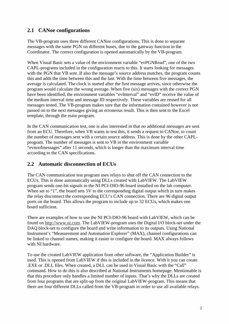
2
2.1 CANoe configurations The VB-program uses three different CANoe configurations. This is done to separate messages with the same PGN on different buses, due to the gateway function in the Coordinator. The correct configuration is opened automatically by the VB-program. When Visual Basic sets a value of the environment variable “evPGNRead”, one of the two CAPL-programs included in the configuration reacts to this. It starts looking for messages with the PGN that VB sent. If also the message’s source address matches, the program counts this and adds the time between this and the last. With the time between five messages, the average is calculated. The clock is started after the first message arrives, since otherwise the program would calculate the wrong average. When five (six) messages with the correct PGN have been identified, the environment variables “evInterval” and “evID” receive the value of the medium interval time and message ID respectively. These variables are reused for all messages tested. The VB-program makes sure that the information contained however is not passed on to the next messages giving an erroneous result. This is then sent to the Excel template, through the main program. In the CAN communication test, one is also interested in that no additional messages are sent from an ECU. Therefore, when VB wants to test this, it sends a request to CANoe, to count the number of messages sent with a certain source address. This is done by the other CAPL-program. The number of messages is sent to VB in the environment variable “evnoofmessages” after 11 seconds, which is longer than the maximum interval time according to the CAN specifications. 2.2 Automatic disconnection of ECUs The CAN communication test program uses relays to shut off the CAN connection to the ECUs. This is done automatically using DLLs created with LabVIEW. The LabVIEW program sends one-bit signals to the NI PCI-DIO-96 board installed on the lab computer. When set to “1”, the board sets 5V to the corresponding digital output which in turn makes the relay disconnect the corresponding ECU’s CAN connection. There are 96 digital output ports on the board. This allows the program to include up to 32 ECUs, which makes one board sufficient. There are examples of how to use the NI PCI-DIO-96 board with LabVIEW, which can be found on http://www.ni.com. The LabVIEW-program uses the Digital I/O block-set under the DAQ block-set to configure the board and write information to its outputs. Using National Instrument’s “Measurement and Automation Explorer” (MAX), channel configurations can be linked to channel names, making it easier to configure the board. MAX always follows with NI hardware. To use the created LabVIEW application from other software, the “Application Builder” is used. This is opened from LabVIEW if this is included in the licence. With it you can create .EXE or .DLL files. When created, a DLL can be used in Visual Basic with the “Call” command. How to do this is also described at National Instruments homepage. Mentionable is that this procedure only handles a limited number of inputs. That’s why the DLLs are created from four programs that are split-up from the original LabVIEW-program. This means that there are four different DLLs called from the VB-program in order to use all available relays.

3
2.3 Presenting the results The Visual Basic program is “controlled” from the Excel template. To know what to test, the program reads the information from Excel. For the program to know where to look however, the template has to have certain properties. These requirements on the template are described in Appendix C, together with an example of the test protocol. If this is followed, the program will not have to be altered each time the CAN specifications change, which is done several times during a truck development process. From the main program the template receives ID and medium interval time for each message, and the number of messages sent from each ECU. It also receives the number of messages tested for the ECU. With these results the status of the messages and ECUs are corrected automatically. All results are also collected automatically in a summary in the beginning of the template.
3 Robustness tests Not much work on the robustness test programs has been done in this project. However, much work is easily done as described below using the knowledge from the CAN communication test program. 3.1 Check CAN communication prior to changing conditions In this test, a CAPL-program will scan the buses in order to find at least one message that is sent from each ECU. Reading the source addresses from all messages and link each address to an ECU does this. If an ECU is identified, the test protocol will mark “Found” on that ECU. Otherwise “Not Found”. This way the tester knows that that ECU sends messages and is therefore supposed to do so also in the forthcoming robustness tests. 3.2 Temporary short-circuit on CAN bus This test is performed as the previous, but first short-circuiting each CAN bus for a couple of seconds before checking ECU status. This is now done manually with the relay program, but is easy to automate using the LabVIEW DLLs instead, being called from the VB-program. 3.3 Error frames on CAN bus There exists a CAPL-program, which transmits error frames on the CAN bus. Pressing certain keys on the keyboard increases or decreases the number of errorframes sent per second. This is easily automated by replacing pressing buttons with environment variables controlled from Visual Basic. While generating error frames, the CAN communication may be monitored as in the two previous robustness tests. 3.4 High message load on CAN bus This test works similar to the previous, but is supposed to check the CAN communication while data frames are sent on the buses instead of errorframes, in order to increase the busload up to certain levels. This is also possible to automate further. However, completely new CAPL-programs will have to be written, since the old ones do not follow the test procedure

4
correctly. The existing CAPL-program sends messages creating a busload up to 90%. This program is however very unstable, using CANoe only. This can be automated similarly as the error frame test. 3.5 Temporary open-circuit on CAN bus This test works similar to the temporary short-circuit test, but open-circuits the CAN buses temporarily instead. The automation possibilities are similar as well. 3.6 Low voltage This test lowers the voltage supply to the test rig, while monitoring messages sent from all ECUs. This is done to see if and in that case when, some ECUs stop working. When increasing the voltage again, it is also noticed when these ECUs start working again. An ECU is in this case said to be functional when it sends the specified CAN messages. The voltage is altered from a LabVIEW program, which controls the analog output of the NI-PCI-6024E board installed on the lab computer. The analog outputs are connected to a port on the back of the power supplier. To control the power supply from the computer instead of with the knobs on the front, a switch beside the control input of the power supplier has to be set to “PROG”. When testing, the batteries have to be disconnected from the rig. This is part of previous automation work, but can be automated further. Now, LabVIEW has to be opened, and is started at the same time as a CAPL-program in order to synchronise these. The results are displayed in a panel in the CANoe configuration. This can be replaced by filling the results into the Excel test protocol directly. However, the test will have to be remade completely in order to become more accurate from what it is now. Now a time buffer of one second is used between LabVIEW and CANoe as the voltage is altered. LabVIEW changes the voltage and one second later CANoe assumes that the voltage is one volt less. This can be done differently, by creating a new LabVIEW-program and make a DLL from it that is called from Visual Basic with the wanted voltage as input. Then when the voltage has been altered, CANoe would check the CAN communication. This should be looped, going through a set of voltages. The reference control input of the power supply is 5.16 V. Therefore all voltages have to be linked to their corresponding control voltages. 3.7 High voltage The high voltage test works similar to the previous, but instead increasing the voltage.
4 User function tests Much information of the functionality of testing the UFs automatically is presented in the main report. Here is presented some additional information of the CANoe configurations and the Excel template. 4.1 CANoe configurations The same configuration can be used for all UFs. A database with one environment variable for each interesting signal is created, so that the read information can be sent to Visual Basic. This database will become larger as more UFs are added. When called from VB, a CAPL-

5
program will send the wanted information back. The values of the different signals are sent each in its own environment variable. The information is sent only once, and is done as soon as it is read from the CAN bus. Often, VB will call for more than one message at the time. The environment variables are given in each signal’s own physical form, by using the CAN database containing all CAN messages defined in the Scania truck. This way the presented information is always displayed to the tester as defined in the CAN database and he will not need to do the conversions himself into percent, km/h or whatever information the signal contains. 4.2 Presenting the results The test protocol used for the automated tests is built up by one sheet for each UF. This is because VB writes the results to specific cells. If the same sheet was used for all tests, all code would have to be altered each time the template was edited. This way the results are also better structured and easier to follow. So far, information is only written to the template. Reading information would mean unnecessary work, since all UFs are different and no general keywords could be used. Since one sheet will be used for each test case there is also no need to do this. This is because editing does not affect other test cases. An example of a UF test template sheet is given in Appendix C.

6

1
Appendix C Below, two of the test templates are presented. The robustness test template is not presented since, even though it looks differently, it has the same requirements as the UF test template. The robustness tests however do not have any requirements on signal values. Instead only an “X” marked in an “OK”-box would signify that the communication is intact, i.e. that the ECU continues transmitting messages. Otherwise the “X” would be marked in the “Not OK”-box.
1 CAN communication test template The requirements on the CAN communication test template have to be met for the test program to work properly. Figure 7 below shows a template that has been filled in with test results. The last message, indexed “X” in the right corner has been ignored by the test program. This is an example of where the tester has to go through the test manually as well. The “Sub-test approved” box has been altered manually in this case, since the template otherwise would require also the last message to be sent. Depending on the configuration of the truck the message may not be supposed to be sent. If interested in understanding the requirements listed below, it helps to have the Excel file opened while reading.
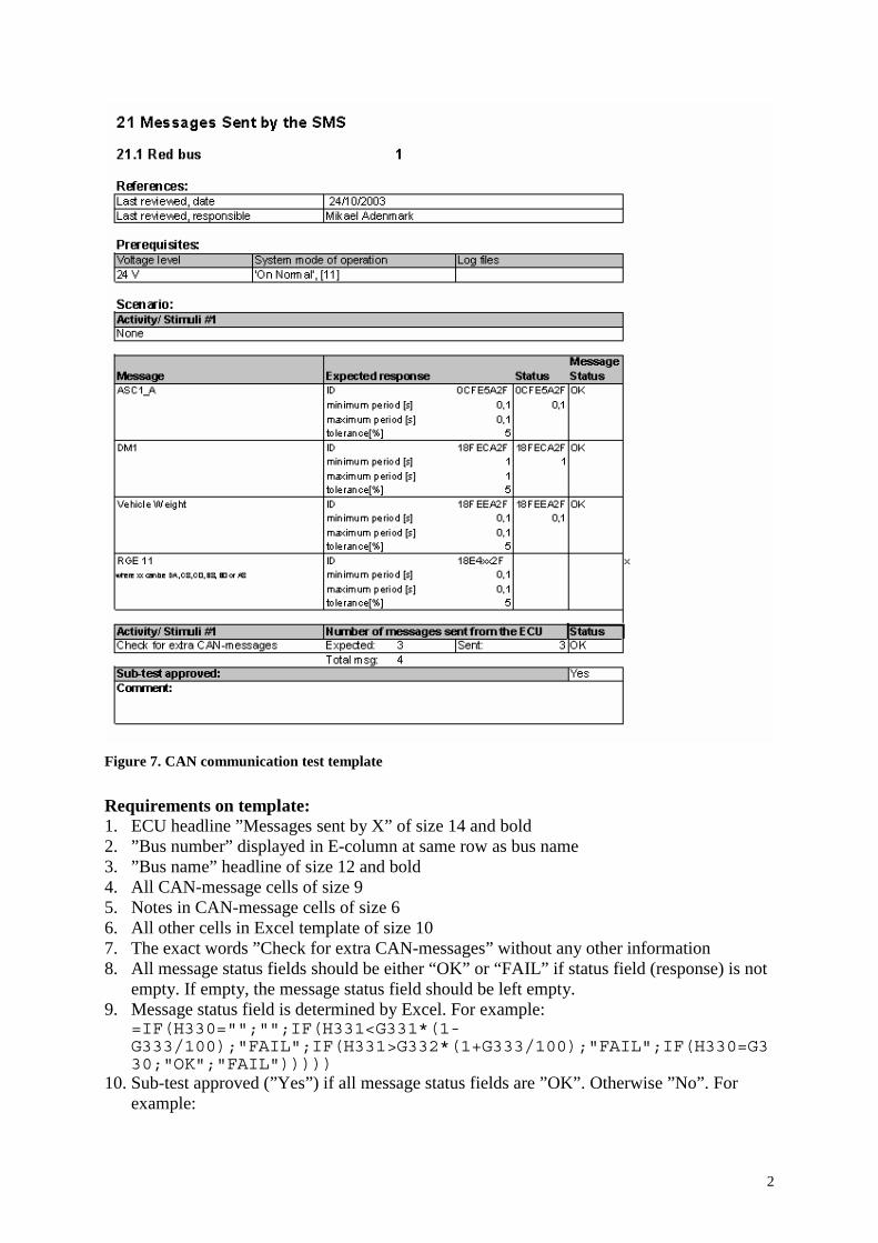
2
Figure 7. CAN communication test template
Requirements on template: 1. ECU headline ”Messages sent by X” of size 14 and bold 2. ”Bus number” displayed in E-column at same row as bus name 3. ”Bus name” headline of size 12 and bold 4. All CAN-message cells of size 9 5. Notes in CAN-message cells of size 6 6. All other cells in Excel template of size 10 7. The exact words ”Check for extra CAN-messages” without any other information 8. All message status fields should be either “OK” or “FAIL” if status field (response) is not
empty. If empty, the message status field should be left empty. 9. Message status field is determined by Excel. For example:
=IF(H330="";"";IF(H331<G331*(1-G333/100);"FAIL";IF(H331>G332*(1+G333/100);"FAIL";IF(H330=G330;"OK";"FAIL")))))
10. Sub-test approved (”Yes”) if all message status fields are ”OK”. Otherwise ”No”. For example:

3
=IF(I340="";"";IF(AND(I330="OK";I334="OK";I340="OK");"Yes";"No"))
2 User Function test template The user function test template does not have the same requirements as the CAN communication template has. Each UF should be written in its own Excel sheet. In this sheet, no changes must be made unless also the VB code is edited to match. This is since the VB code tells exactly which cells to write the results to. The template illustrated below is left blank. The Sub-test is approved if all settings are “OK”.
Figure 8. UF test template

4

1
Appendix D The following chapters are presented in order to make the reader acquainted with the programming environment of this master’s thesis project.
1 Communicating with the dSPACE hardware This command is used to control wheel speed from the VB program. The command runs an existing m-file that in turn calls the dSPACE hardware as defined in a Simulink model. The m-file (chwhtcospeed.m in this case) increases the speed with 1 km/h at the time, in short intervals, until the total wanted change is performed. MatLab.Execute ("mlib(chwhtcospeed(40,40,40,40))") Extract from chwhtcospeed.m: Function chwhTCOspeed(ch1,ch2,ch3,ch4) mlib('selectboard','ds1005') wh1=mlib('gettrcvar','Tunable Parameters/wheelspeed1'); .. for i=0:1:maxchange if i < abs(ch1) mlib('write',wh1,'data',mlib('read',wh1)+sign(ch1)) end .. pause(0.1) end Another m-file changes the wheel speeds instantly in order to simulate wheel locking or spinning wheel. There are also Matlab files for changing tachograph speed and engine speed. Another Matlab file initiates dSPACE and Controldesk, which is done only once: Extract from init-dspace.m: wheelspeed1=0; .. open_system('wheelspeed4wheels.mdl') make_rti close_system('wheelspeed4wheels') !ControlDesk c:\user_sw\inttest-dspace\wheelspeed4wheels.cdx -m ANIMATION & The last line opens Controldesk in order to visualise all generated vehicle signals to the tester. This is however not mandatory.
2 Disconnection of ECUs The ECU connections are controlled from a LabVIEW application that has been converted to a DLL. The following commands are examples of how the connection/disconnection may be performed. “SetVec” creates a byte vector (eight bits, with index 0-7). P1to47 is in this case the name of the LabVIEW DLL. There are four LabVIEW DLLs, each controlling three bytes of information. Together that makes 96 bits, which is the number of DIO-pins on the NI DIO-

2
96 board. TCOsuppl and the other inputs all have the values 0 or 1, depending on if their corresponding relays should be “open” or “closed”. Dim pin_1to15(7) As Byte ‘odd pins .. SetVec pin_1to15, TCOsuppl, TCOgnd, TCOcan, EBSsuppl, EBSgnd, EBScan, EMSsuppl, EMSgnd .. Call P1to47(pin_1to15(0), pin_17to31(0), pin_33to47(0))
3 Information from CANoe and presentation in Excel The following code acquires information from a CANoe environment variable (evEBC2WhSpeedProp_FrontAxleSpeed in this case). These have to be listed in a CANoe-database before used. Then the values are sent to a specified Excel cell. Private envvarEBC2WhSpeedProp_FrontAxleSpeed As EnvironmentVariable .. Set envvarEBC2WhSpeedProp_FrontAxleSpeed = CANEnv.GetVariable("evEBC2WhSpeedProp_FrontAxleSpeed") .. Worksheets("UF121C").Cells(rowindex + 10, 5) = envvarEBC2WhSpeedProp_FrontAxleSpeed The environment variables may also be handled “on change”. For instance, when the environment variable changes in CANoe, it may be written instantly to the Excel template. This is for example done in the CAN-communication test: Private Sub ID_OnChange(ByVal value As Variant) ResultStatus = 1 End Sub When “ResultStatus” changes to 1, the new ID is written to Excel. This is done in a loop that lets the system do external events until the ID changes or until the message should have been registered.
4 CAPL-programs This code is part of the CAN-communication CAPL-program scanning the red bus: on pg CAN1.* { .. if (this.PGN == getvalue(evPGNRead)) { .. putValue(evID, this.ID); write("ID of message with this PGN is %X",this.ID); }} The event on which the code is run, is any message sent on the red bus. The program checks if the registered message PGN matches the wanted (evPGNRead, sent from Excel via Visual Basic). When all other criteria is met, the response is sent with the environment variable with

3
the command putValue. The result is also written to the CANoe write window, so that the tester may follow the procedure.