automation - ican-motor.comican-motor.com/wp-content/uploads/2018/07/3mr8.pdf · 3mr8 3phase...
TRANSCRIPT

3MR8
Automation
3-PHASE STEPPER MOTOR DRIVE
Dongguan ICAN Technology Co., Ltd
User manual
ICAN July 2016 2
3MR8
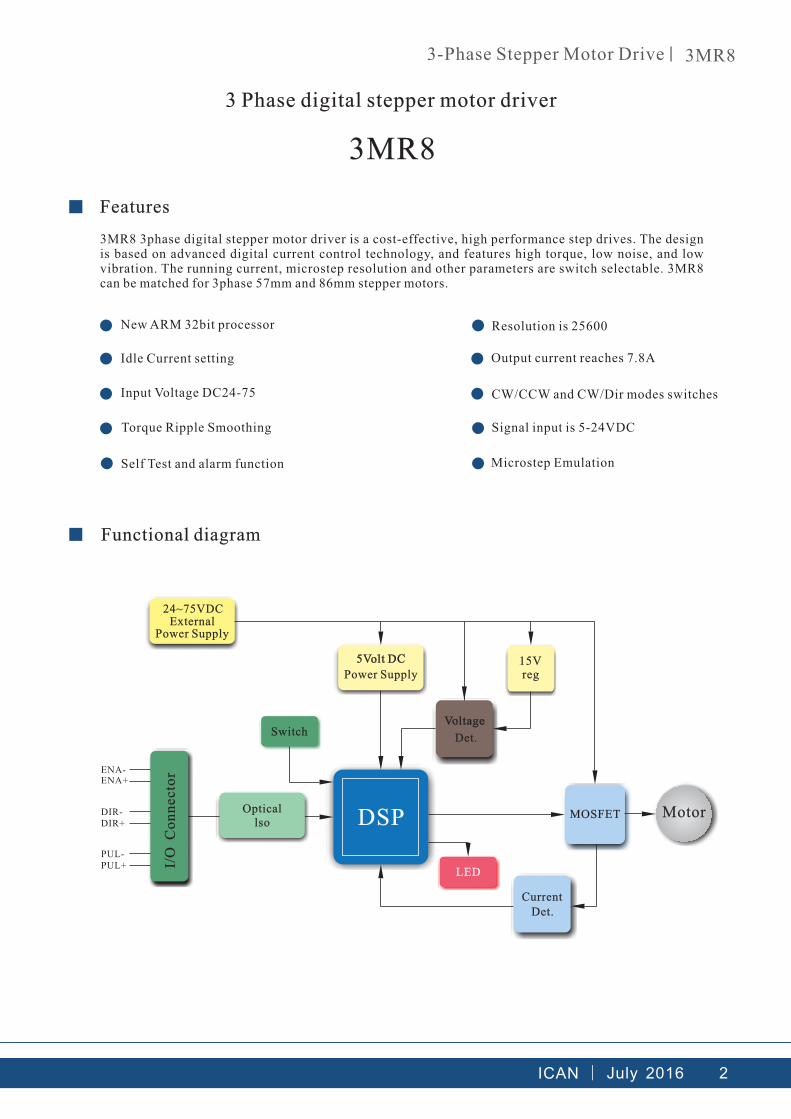
ExternalPower Supply
Power Supply
Det.
CurrentDet.
MotorMOSFET
15V reg
Switch
LED
DSP
I/O
Co
nn
ecto
r
Opticallso
ENA-ENA+
DIR-DIR+
PUL-PUL+
24~75VDC
3-Phase Stepper Motor Drive 3MR8
3 Phase digital stepper motor driver
■ Features
3MR8 3phase digital stepper motor driver is a cost-effective, high performance step drives. The design is based on advanced digital current control technology, and features high torque, low noise, and low vibration. The running current, microstep resolution and other parameters are switch selectable. 3MR8 can be matched for 3phase 57mm and 86mm stepper motors.
●
●
●
●
●
●
●
●
●
●
New ARM 32bit processor Resolution is 25600
Idle Current setting Output current reaches 7.8A
Input Voltage DC24-75 CW/CCW and CW/Dir modes switches
Torque Ripple Smoothing Signal input is 5-24VDC
Self Test and alarm function Microstep Emulation
■ Functional diagram
ICAN July 2016 3
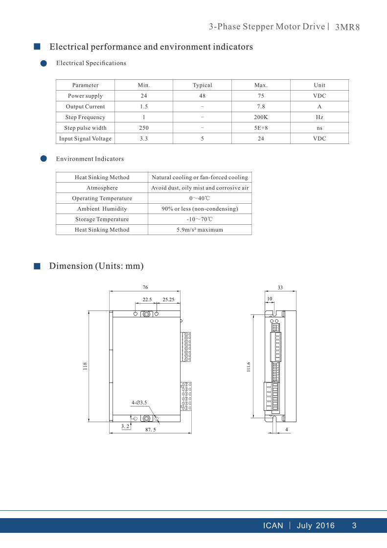
Parameter Min. Typical Max. Unit
Power supply 24 48 75 VDC
Output Current 1.5 - 7.8 A
Step Frequency 1 - 200K Hz
Step pulse width 250 - 5E+8 ns
Input Signal Voltage 3.3 5 24 VDC
10
33
12
34
56
78
N01
23
N0
76
22.5 25.25
4-∅3.5
3.287.5
111.
6
4
3-Phase Stepper Motor Drive 3MR8
■ Electrical performance and environment indicators
● Electrical Specifications
● Environment Indicators
Heat Sinking Method Natural cooling or fan-forced cooling
Atmosphere Avoid dust, oily mist and corrosive air
Operating Temperature 0~40℃
Ambient Humidity 90% or less (non-condensing)
Storage Temperature -10~70℃
Heat Sinking Method 5.9m/s² maximum
■ Dimension (Units: mm)
ICAN July 2016 4
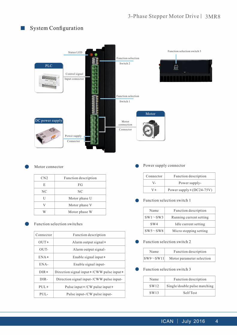
PLC
●
Name Function description
SW9~SW11 Motor parameter selection
●
Connector Function description
V- Power supply-
V+ Power supply+(DC24-75V)
●
Name Function description
SW1~SW3 Running current setting
SW4 Idle current setting
SW5~SW8 Micro stepping setting
●
Name Function description
SW12 Single/double pulse matching
SW13 Self Test
3-Phase Stepper Motor Drive 3MR8
■ System Configuration
Status LED
Control signal
Input connector
Function selection
Function selection switch 3
Function selection switch 1
Function selection switch 2
Function selection switch 3
Function selection
Switch 2
Switch 1
Power supply
Connector
DC power supply
Motor
Motor connection
Connector
CN2 Function description
E FG
NC NC
U Motor phase U
V Motor phase V
W Motor phase W
● Motor connector
● Function selection switches
Connector Function description
OUT+ Alarm output signal+
OUT- Alarm output signal-
ENA+ Enable signal input+
ENA- Enable signal input-
DIR+ Direction signal input+/CWW pulse input+
DIR- Direction signal input-/CWW pulse input-
PUL+ Pulse input+/CW pulse input+
PUL- Pulse input-/CW pulse input-
Power supply connector

ICAN July 2016 5
U
V W
U
V W
3-Phase Stepper Motor Drive 3MR8
To change the direction of motor, customers only need to change the line sequence of one of U V W phases. Star connection and triangular connection are available for 3 phase motors. Star connection is for low speed occasions and triangular connection is for high speed occasions.
Star connection Triangular connection
■ Connecting the motor

6ICAN July 2016ICAN
DIR+
DIR-
ENA+
ENA-
PUL+
PUL-
DIR/CWW
VCC
PUL/CW
ENA
DIR/CWW
PUL/CW
DIR+
DIR-
ENA+
ENA-
PUL+
PUL-
VCC
VCC
VCC
ENA
DIR+
DIR-
ENA+
ENA-
PUL+
PUL-
DIR/CWW
PUL/CW
ENA
3-Phase Stepper Motor Drive 3MR8
■ Control signal input
The control signal is OC input; the voltage ranges DC5-24V. The largest step frequency is 200KHz and rising edge is valid.
Common anode
Controller Motor driver
Common cathode
Controller
Motor driver
Difference
Controller Motor driver
Enable signal
Direction signal
Pulse

DC5~24V
ALM+
ALM-
ICAN July 2016 7
0V
DC5~24V
ALM+
ALM-
Vu
0V
Vu
ALM+
ALM-
DC5~24V电源 +
-
Vu
3-Phase Stepper Motor Drive 3MR8
●
Alarm signal output is OC. The maximum saturation voltage is 30V and maximum saturation current is 100mA.
Alarm signal output
Common anode
Controller Motor driver
Common cathode
Controller
Motor driver
Relay
Relay Motor driver

ICAN July 2016 8
SW12
K
E
SW13
K
E
SW4
K
E
3-Phase Stepper Motor Drive 3MR8
■ Function setting
● Pulse Input Mode
CW/CCW mode: SW12=ON PUL/DIR mode: SW12=OFF (factory setting)
The setting will take effect after recycle the power
CW/CCW Pulse
When pulse is input at PUL/CW terminal, the motor will rotate by one step in one direction.
When pulse is input at DIR/CWW terminal,the motor will rotate by one step in the other direction.
PUL/CWHL
H
LDIR/CWW
CW
CWWMotor Motion
Above 2μs
Pulse & Direction
When pulse is input at PUL terminal, and DIR terminal is high voltage, the motor will rotate by one step in one direction. When pulse is input at PUL terminal, and DIR terminal is low voltage, the motor will rotate by one step in the other direction.
HL
H
L
CW
CWW
Above 2μs Above 2μs
PUL input
DIR input
Motor Motion
Setting switch SW13 to ON after the drive is powered up will cause the drive to perform a self test rotate the motor back and forth, two turns in each direction, setting switch SW13to OFF will disable this feature.
● Self Test
●
The running current of the motor driver is automatically reduced whenever the motor hasn’t moved for 1 second. Setting the SW4 switch to ON reduces the current to 50% of its running value. Setting this switch to OFF maintains 90% of the running current. This 90% setting is useful when a high holding torque is required. To minimize motor and drive heating it is highly recommended that the idle current reduction feature be set to 50% unless the application requires the higher setting.
Idle Current
ICAN July 2016 9
Peak running current SW1 SW2 SW3
1.5A OFF OFF OFF
2.0A ON OFF OFF
3.0A OFF ON OFF
4.0A ON ON OFF
5.2A OFF OFF ON
5.8A ON OFF ON
7.0A OFF ON ON
7.8A ON ON ON
Resolution(step/r) SW5 SW6 SW7 SW8
200 ON ON ON ON
400 OFF ON ON ON
800 ON OFF ON ON
1600 OFF OFF ON ON
3200 ON ON OFF ON
6400 OFF ON OFF ON
12800 ON OFF OFF ON
25600 OFF OFF OFF ON
1000 ON ON ON OFF
2000 OFF ON ON OFF
4000 ON OFF ON OFF
5000 OFF OFF ON OFF
8000 ON ON OFF OFF
10000 OFF ON OFF OFF
20000 ON OFF OFF OFF
25000 OFF OFF OFF OFF
SW5
K
ESW6 SW7 SW8
SW2
K
ESW3SW1
3-Phase Stepper Motor Drive 3MR8
● EN Input
The EN input enables or disables the drive amplifier. When EN input is ON the drive amplifier. When EN input is ON the drive amplifier is deactivated. All the mosfets will shut down, and the motor will be free. When EN input is OFF, the drive is activated. A falling signal into the EN input will reset the error status and activate the drive amplifier again.
● Running current
The output current of the driver is set by the SW1, SW2 and SW3 switches and can be changed as necessary. There are 8 settings available according to the ON/OFF combination of the switches. Normally, customers set the current same with the motor rated current.
● Microstepping
The microstep resolution is set by the SW5, SW6, SW7 and SW8 switches. There are 16 settings.

ICAN July 2016 10
K
E
Recommended motorHolding
Torque(Nm)SW9 SW10 SW11 Flange size
Recommended voltage
57H3P4124A6 0.4Nm ON ON OFF
57
24VDC
57H3P5656A6 0.9Nm OFF ON OFF 24VDC
57H3P7652A3 1.2Nm ON OFF OFF 48VDC
60H3P7845A3 1.5Nm ON ON ON 60 48VDC
85H3P6831A3 1.6Nm OFF ON ON
85
48VDC
85H3P9758A3 4.5Nm ON OFF ON 68VDC
85H3P12752A3 6.0Nm OFF OFF ON 68VDC
SW9 10 11
3-Phase Stepper Motor Drive 3MR8
● Anti Resonance
To optimize the system performance to gain fastest feedback, customers are allowed to select parameters (based on SW9, SW10 and SW11) to match the motor size, motor inductance.
The recommended motors are our motors. If performance is not good after switching according to the above tab, please contact us with motor parameters.

11ICAN July 2016ICAN
3-Phase Stepper Motor Drive 3MR8
■ Troubleshooting
Situation Possible cause Suggestion
Motor disabled
Motor is in EN status Input a falling signal into the EN input.
Wrong wiring Check the wiring and make sure connection is right
Output current is low Set the switch to set suitable current
Microstep resolution is low Set the resolution higher
No pulse signal input Make sure pulse signal input
Input pulse signal is weak Make sure the input signal voltage DC5-24V, 7-16Ma
CW and CWW signal are input simultaneously Make sure the pulse input mode
No power supply Make sure power supply works
Motor motion is not
smooth
Motor speed is in resonance zone Set the microstep resolution higher
External interference existsMake sure the interference source and interference position
The amount of movement of the motor var ies wi th the set value
Microstep resolution is not right Set the right resolution
Output current is low Set the switch to set suitable current
Motor out of step
Acceleration / deceleration time is too short Set the Acceleration / deceleration time longer
Rated torque is low Select suitable motor
Start frequency is too high set the frequency lower when start
Current value is low Set the current higher
Voltage value is low Set the voltage higher
External interference existsMake sure the interference source and interference position

12ICAN July 2016ICAN
ModelHolding
Torque(Nm)Current/phase(A)
Resistance(Ω)
Inductance(mH)
Diameter of axle X(mm)
Axial length L1(mm)
Motor Length L(mm)
57H3P4124A3 0.4 2.4 3.4 4.0 6.35 20.6 41
57H3P5656A3 0.9 5.6 0.5 1.1 6.35 20.6 56
57H3P7652A3 1.2 5.2 0.5 1.4 8 20.6 76
L1 L
1.6
15
56.4±1
47.14±0.2
56.
4±1
47
.14±
0.2
4-∅55
400min
0+
∅3
8.1
_-
0.0
12
0+∅X_ -0.013
0 1.
0 2.
0 3.
0 4.
160 320 480 640 800 960
0 2.
0 4.
0 6.
0 8.
160 320 480 640 800 960
1 0.
0.25
0.50
0.75
1.00
160 320 480 640 800 960
1.25
0
0
0
24V
48V
24V
48V
24V
48V
3-Phase Stepper Motor Drive 3MR8
■ Recommended motor
● 3 phase hybrid nema 23 stepper motor
unit:mm
Motor:57H3P4124A3
Driver:3MR8
Subdivision 20 Step/r: 00
Current:2 0. A
Motor:57H3P5656A3
Driver:3MR8
Subdivision 2000 Step/r:
Current:5 2. A
Ho
ldin
g T
orq
ue
N.m
Ho
ldin
g T
orq
ue
N.m
Speed rpm Speed rpm
Motor:57H3P7652A3
Driver:3MR8
Subdivision 2000 Step/r:
Current:5 2. A
Speed rpm
Ho
ldin
g T
orq
ue
N.m

13ICAN July 2016ICAN
ModelHolding
Torque(Nm)Current/phase(A)
Resistance(Ω)
Inductance(mH)
Diameter of axle X(mm)
Axial length L1(mm)
Motor Length L(mm)
85H3P6858A3 2 5.8 0.52 1.5 12 31 68
85H3P9758A3 3.2 5.8 0.53 2.5 12 31 97
85H3P12558A3 6.0 5.8 0.87 6.1 14 31 125
L1 L
69.9±0.2
85
85
69.
9±0
.2
4-∅5.
5
400min
23
8
2
0+
∅7
3_
-0
.03
0+∅X_ -0.012
0.4
0.8
1.2
1.6
160 320 480 640 800 960
2.0
0.7
1.4
2.1
2.8
160 320 480 640 800 960
3.5
1.2
2.4
3.6
4.8
160 320 480 640 800 960
6.0
0
0
0
3-Phase Stepper Motor Drive 3MR8
● 3 phase hybrid nema 34 stepper motor
unit:mm
24V
48V
Motor:85H3P6858A3
Driver:3MR8
Subdivision 20 Step/r: 00
Current:5 8. A
24V
48V
Motor:85H3P9758A3
Driver:3MR8
Subdivision 2000 Step/r:
Current:5 8. A
Ho
ldin
g T
orq
ue
N.m
Speed rpm Speed rpm
Ho
ldin
g T
orq
ue
N.m
24V
48V
Motor:85H3P12558A3
Driver:3MR8
Subdivision 2000 Step/r:
Current:5 8. A
Ho
ldin
g T
orq
ue
N.m
Speed rpm

Add:4/F, Block B, RuiLian Zhenxing Industrial Park, Wanjiang District, Dongguan City, Guangdong Province, ChinaTel: 086-0769-22327568
Fax:086-0769-22327578
ican-tech.en.alibaba.com Website:
After sale service
Warranty period
Dongguan ICAN Technology provides warranty for 1 year from the date of shipping.
Maintenance process
1) Get the maintenance permission
2) Ship the package to the following address: 4/F, Block B, RuiLian Zhenxing Industrial Park,
Wanjiang District, Dongguan City, Guangdong Province
Tel: 86-0769-22327568
Return policy
1. After use or man-made damage condition (etc, wrong wiring), no return
2. ICAN Technology guarantees the product quality, but product incompatibility is not in the return or maintain condition.3. Customers don’t use the products under the specified electrical performance and environment indicators, no maintain condition
Automation
Dongguan ICAN Technology Co., Ltd
Scan the QR code to follow us on Wechat