automating the loading of business process data warehouses · process warehousing, the existing...
TRANSCRIPT

Automating the Loading of Business Process Data Warehouses
Malu Castellanos HP Labs
Palo Alto, Ca, USA [email protected]
Alkis Simitsis HP Labs
Palo Alto, Ca, USA [email protected]
Kevin Wilkinson HP Labs
Palo Alto, Ca, USA [email protected]
Umeshwar Dayal HP Labs
Palo Alto, Ca, USA [email protected]
ABSTRACT Business processes drive the operations of an enterprise. In the past, the focus was primarily on business process design, model-ing, and automation. Recently, enterprises have realized that they can benefit tremendously from analyzing the behavior of their business processes with the objective of optimizing or improving them. In our research, we address the problem of warehousing business process execution data so that we can analyze their be-havior using the analytic and reporting tools that are available in data warehouse environments. We build upon our previous work that described the design and implementation of a generic process data warehouse for use with any business processes. In this paper, we show how to automate the population of the generic process warehouse by tracking business events from an application envi-ronment. Typically, the source data consists of event streams that indicate changes in the business process state (i.e., progression of the process). The target schema is designed to allow querying of task and process execution data. The core of our approach for processing progression data relies on the construction of generic templates that specify the semantics of the event streams extrac-tion and the subsequent transformations that translate the underly-ing IT events into business data changes. Using this extensible template mechanism, we show how to automate the construction of mappings to populate the generic process warehouse using two-levels of mappings that are applied in two-phases. Interes-tingly, our approach of using ETL technology for warehousing process data can be seen the other way around. An arbitrary ETL process can be modeled as a business process. Hence, we describe the benefit of modeling ETL as a business process and illustrate how to use our approach to warehouse ETL execution data, and to monitor and analyze the progress of ETL processes. Finally, we discuss implementation issues.
1. INTRODUCTION Over the years enterprises have invested in technology to improve the business processes underlying their operations. In the nineties, the focus was on business process automation, whereas recently the focus has shifted towards business process monitoring, report-ing and optimization via analytics. Business processes typically involve a large number of people and systems (applications, data-
base systems, web servers, message brokers, etc.) Events generat-ed by these systems signal the start or end of steps of the process, and hence mark the progression of the process execution. By cap-turing these events, it is possible to load a data warehouse with process progression data derived from the events (see Figure 1). Once loaded, progression data can be queried to obtain process execution information including measures on the quality, effi-ciency, and timeliness of process execution, as well as to under-stand areas for improvements.
A solution for process warehousing addresses two problems: the design of the process data warehouse, and extracting process in-stance data and loading the process warehouse. In our previous work, we tackled the first problem and described the design of a generic process data warehouse that could be used for any busi-ness process [3]. In this paper, we address the second problem by automating the design and implementation of Extract-Transform-Load (ETL) scenarios to populate the process warehouse.
In general, ETL design for data warehouses is a time-consuming, non-trivial task performed manually by ETL experts who have a good understanding of the semantics of the source and target schemas. Efforts to automate this task have had limited success, since it is difficult to come up with a generic method that works for all source and target schemas. However, in the process ware-house context the target schema can be fixed, since the process data warehouse model described in [3] is generic, and the source data consists of streams of events that cause changes in the process state. Consequently, the automation of the ETL design is feasible in the process warehouse context, and in this work, we demonstrate how we can achieve that.
Three notions are central to our approach: data independence, genericity and abstraction. Data independence shields the process progression from the infrastructure so that changes in the infra-structure do not impact the mappings to process progression data. This is achieved through a level of indirection given by a two-phase mapping mechanism. Abstraction enables the user to have a high level view of the process and specify high level mappings without having to know the details of the process or the imple-mentation details. Genericity is obtained by factoring out the part that is common to all processes while leaving room for the part that is specific to a particular process.
The core of our approach relies on the construction of generic templates that specify the semantics of the extraction from event streams and the required two-phase transformations from the un-derlying IT events to business data changes to process progression data. Our mechanism includes (a) the extraction of stream events in a near real time fashion, (b) a two-phase, two-level mapping procedure that starts with high level (declarative) mappings and
Permission to copy without fee all or part of this material is granted provided that the copies are not made or distributed for direct commer-cial advantage, the ACM copyright notice and the title of the publication and its date appear, and notice is given that copying is by permission of the ACM. To copy otherwise, or to republish, to post on servers or to redistribute to lists, requires a fee and/or special permissions from the publisher, ACM. EDBT'09, March 24-26, 2009, Saint Petersburg, Russia. Copyright 2009 ACM 978-1-60558-422-5/09/0003 ...$5.00.
612

Figure 1. Business process warehousing context
ends with appropriate executable (prescriptive) ones, and (c) the loading of the mapped data into the process warehouse. The whole procedure is realized in a streaming fashion, which fits with the real-time nature of the business processes environment.
Contributions. Our main contributions are as follows:
- We propose a generic approach, based on templates and a two-phase, two-level mapping procedure, for automating the design and implementation of ETL for business processes.
- We present a novel mechanism for extracting business events from an application environment in near real-time.
- We describe a template language that includes useful con-structs for defining appropriate templates.
- We discuss how our approach can be used for monitoring the ETL processes themselves by modeling them as a business processes.
- We present a prototype implementation of our approach.
Outline. In Section 2, we give some notions relevant to business process warehousing and describe our two-phase-transformation, two-level-mapping framework. In Section 3, we describe our template-based approach for generating mappings, as well as a language to define transformation templates. In Section 4, we present our prototype implementation. We then adapt these con-cepts to arbitrary ETL applications. In Section 5, we show how ETL itself can be modeled as a process and use our approach to warehouse ETL execution data. Finally, we discuss related efforts (Section 6) and conclude with future directions (Section 7).
2. BUSINESS PROCESS WAREHOUSING In this section, we present the main concepts related to business process warehousing, the existing challenges, and the approach we follow for populating a process data warehouse.
2.1 Challenges There are three main challenges in business process warehousing: genericity, abstraction, and data independence.
Figure 2. Supply chain process
Genericity. Developing ad hoc, process-specific solutions for warehousing process data is not a sustainable model. Thus, one of the main challenges is that of developing a general and reusable solution for process data warehousing, applicable to most or all the processes in an enterprise. Furthermore, our approach can be extended to other applications that have similar characteristics.
Abstraction. A typical process executed in the underlying IT sys-tems is very detailed and consists of hundreds of steps, including manual operations (e.g., scanning invoices), database transactions, and application invocations. However, having visibility (report-ing, analytics, etc.) at this level of detail is confusing for analysts who have a much higher level abstract view of the process. The common wisdom is that business analysts and managers perceive a process as being composed of approximately 5 to 7 steps. Ser-vice level agreements (SLA’s) and key performance indicators (KPI’s) are also defined on abstracted views of a process. An appropriate example is presented in Section 2.2.
Data independence. The infrastructure underlying the process execution is subject to dynamic changes and it is important to shield the process warehouse from those changes. For example, the infrastructure that handles the notification of acceptance of an order could evolve from database technology where a purchase order record is updated, to a more proactive service-oriented technology where a message is sent to a web service that handles the notification. This change should not affect the process ware-house schema or the mappings to its tables. The challenge is in developing a solution that provides this kind of independence.
2.2 A Business Process Example Figure 2 shows an abstracted model of a simple supply chain process. (Note that we could define the process in a standard business process language such as BPEL [25]; however, this is irrelevant to our approach, indeed we do not require a BPEL or other execution engine to implement the process.) Each node represents a task (also called step or activity) of the supply chain process. Clearly, this is not the actual implemented version of the process since each step in the figure actually corresponds to sev-eral finer granularity steps. For example, the step CheckGoodsA-vailabilityWithVendor could correspond to the following sequence of steps: FillRequestForm, SubmitRequestForm, ReceiveVendor-Response.
IT events occur when a task starts or ends and cause transitions among tasks. Therefore, as events happen, process execution progresses. For example, at the moment a particular web page is accessed, the task Receive_and_check_PO_request is started, when the user leaves the page, the task ends. The occurrence of these two events (web page visit and web page exit) marks the execution of this task. As tasks are executed, the process progresses. Typically, events are recorded in logs which can then
613

be queried and mined to monitor and analyze the process flow. However, when near real-time is desired the events are captured in a streaming fashion directly from the event sources. These events are extracted by our ETL process and transformed into process and task execution data to reflect process progression.
2.3 Process Data Warehouse Model The process data warehouse model was designed to be generic to support the analysis of arbitrary business processes, and to sup-port the computation of a large variety of process metrics [3].
Figure 3 shows the most significant elements of the process data warehouse model. It consists of two main logical parts that represent the business data and the process progression data. In this paper, we focus on the latter part which includes all the tables in Figure 3 except the business tables Purchase_Order_Data and Vendor. The main fact table is TaskExecution, which captures the process progression in terms of the executed tasks (e.g., Receive_ and_check_PO_Request start), and ProcessInstance which is a fact table that records instances of a process (e.g., each processed order).These tables are generic in the sense that they apply to any business process. On the other hand, the part of the data ware-house responsible for the business data includes process-specific tables to track business data relevant for each process, e.g Pur-chase_Order_Data is specific to supply chain processes. Due to space limitations, we refer the interested reader to [3] for details.
2.4 Population of a Process Warehouse In this section, we present an overview of our solution to the problem of warehousing abstracted process representations, which relies on two main mechanisms. First, a modeling tool, like HP Business Process Insight (BPI) [1], is needed for letting the user describe an abstracted (high level) view of the process as well as how its progression maps to the underlying IT events. This procedure involves the following tasks:
− Describing the process flow. For example, the process model in Figure 2 was defined with the BPI modeler.
− Specifying high level (declarative) mappings between IT events and business data. For instance, mapping the event given by the submission of a form on a given URL to the creation of a new purchase order record.
− Specifying high level (declarative) mappings between changes in business data and the start and completion of each process task. For example, a change to the value “accepted” in the PO_status value of a Purchase_Order_Data instance is associated with the end of the NotifyAcceptance task.
− Defining the correlation logic to associate (a) events with the correct business data instance and (b) a change in a business data instance to the appropriate business process instance. For the previous example, the correlation logic would indi-cate that the identifier (PO_number attribute) of the purchase order instance should be the same as the process instance identifier (top_work_object_key attribute) of the NotifyAc-ceptance task instance in the Task_Execution fact table.
− Associating process tasks with human or automated re-sources. For example, associating a specific web server with the task Receive_and_check_PO_Request.
Figure 3. Process warehouse model [3]
The ETL mechanism for populating the process data warehouse with process execution data. is abstractly depicted in Figure 4. It relies on the abstract process definition and the events occurring at the different systems. A probing mechanism (e.g., OpenAdap-tor [12]) is needed for capturing the events from different source systems (e.g., a web or an application server). The next step is to gather the events (extraction stage) and then, to perform the ap-propriate mappings (transformation stage). For the first, we re-quire a means to gather the events in a streaming fashion. Hence, we provide an extraction component that has the capability to deal with streams of events in near real-time. For the next stage (i.e., transformation), the challenge is to find means for representing the high level specifications that only define what are the mappings, as low level ones that describe how to execute the mappings (i.e., how to interpret them at run-time to update business and process execution data in the warehouse). Our approach uses a two-level mapping process that distin-guishes a logical and a physical level. For the first level, of par-ticular importance is the template mechanism that automates the generation of logical mappings with specific types of events, business data and process data. In the second level a translator mechanism is used to automatically generate physical (executa-ble) mappings from the logical ones previously generated. Logical Mapping. The logical mappings are automatically gener-ated from the high level (declarative) mappings and the correla-tion logic defined by the user at modeling time and accessible from the modeling tool repository. We use a template-based ap-proach, described in Section 3.2, where the operational semantics of the mappings, given by high level transformations, are embed-ded in mapping templates. When a record enters this phase, the respective mapping template is instantiated and the resulting logi-cal mapping becomes readily available to feed the next phase. Logical mappings, although already prescriptive, are not executa-ble. The idea is to make this mapping level agnostic to any specif-ic ETL implementation tool or language.
614

Figure 4. Framework for warehousing business processes
Physical Mapping. The physical mappings are expressed in a specific ETL implementation language and are automatically generated from the logical ones (specifically, from the instantia-tedmapping templates which comprise the output of the previous level) using translators that combine the logical templates with appropriate physical operators of specific ETL engines (e.g., In-formatica Power Center, Oracle Warehouse Builder) or imple-mentation language (e.g., PL-SQL, C) constructs. The process is described in detail in Section 3.3. In addition to being a two-level mapping process as depicted in Figure 4, our approach for automating the design and implementa-tion of the ETL that populates the business process warehouse is also a two-phase transformation process. This mechanism ad-dresses the data independence requirement fulfilled by the intro-duction of an isolation layer formed by business data. By map-ping IT events to changes on business data (first phase) we achieve stability in the process warehouse schema and in the mappings from this layer to the process progression tables in the warehouse (second phase). For example, an acceptance notifica-tion event is mapped to an update on the PO_status attribute of a Purchase_ Order_Data record rather than to process execution data. It is then that the business data change is mapped to the process progression tables. For the same example, the update on the data record is now mapped to the end of the Noti-fy_acceptance task. Hence, the need for a two-phased mapping procedure that requires the specification of two types of declara-tive mappings as part of the abstracted process model: (a) map-pings from IT events data to business data changes, and (b) map-pings from the latter to process progression data. Our approach deals with both kinds of mappings in a uniform way. First, logical mappings are generated from thedeclarative ones by using tem-plates. Second, physical mappings are produced from the logical ones by specific translators. Note that the two-level mapping process is orthogonal to the two-phase transformation one: both levels of mappings (logical and physical) apply to each transfor-mation phase (from events to business data changes and from the latter to process progression).
The approach presented in this paper is applicable to data ware-housing in general. The idea of using a two phase, two level map-ping process, mapping templates and a near real-time extraction mechanism can be generalized to other data warehouse applica-tions. As long as appropriate templates capturing the operational semantics of user specified high level mappings can be pre-defined (which in turn requires knowledge about the semantics of the source and target data warehouse schemas), the whole machi-nery of this approach can be applied to automatically generate the design and implementation of ETL processes. In addition, we present a language powerful enough to define templates of any level of complexity.
3. ETL APPROACH In this section, we describe the near real-time extraction of stream events, and we elaborate on how the template and translation mechanisms cooperate to produce the corresponding mappings.
3.1 Data Extraction For business process data warehouses, the source data consists of event streams that cause changes in the process state. We describe two approaches for extracting event data from the sources: a batch oriented approach and a near real-time approach.
3.1.1 Batch-oriented approach Traditionally, ETL processes work in batch mode. Periodically, usually during the night, they collect data from different hetero-geneous sources and after massaging –e.g., cleaning and homoge-nizing– those data, they load them to a target data warehouse. During the extraction, the source data are extracted from the sources and are propagated to a data staging area (DSA) [10]. The propagation of data usually involves several operations like file transfer, compression, encryption, and so on. Whereas all these operations are performed in a pipelining fashion, when the data arrive into the staging area, they are stored into landing tables. Figure 5(a) depicts a typical extraction scenario.
The data, after their landing in Lnew are compared against a snap-shot of the previous landing Lold, to discriminate the newly in-serted, deleted, and updated tuples. This comparison is performed through a difference operator, Diff, which checks for equality only on a certain subset of the tuples’ attributes (e.g., the business keys). Let A be the set of attributes and B a subset of those, con-sidered for the equality check. For finding the newly inserted tuples, we use the expression:
ΔB(Lnew,Lold) = {x∈Lnew | ¬ y∈Lold: x[b1]=y[b1]∧...∧x[bn]=y[bn]}
where b1,…,bn∈B. For finding an updated tuple, we consider that for each such tuple, there already exists a tuple in Lold having the same values for B with the respective tuple in Lnew and at the same time, at least one attribute belonging to A\B has a changed value. (If A=B then we can use the classical relational difference operator.) By reversing the use of the difference operator, we obtain the deleted tuples.
After this step, appropriate timestamps are assigned to the data before their propagation to the upcoming transformation phase. (Note that another almost equivalent technique, which we won’t discuss further, is based on the data been time-stamped at the
615

eventLand
L_NEWDiff
L_OLD
deleterename
Δ(event)Get_Timestamp
Figure 5. Extraction phase: (a) batch mode and (b) near real-time mode
source sites.) The last step of this phase is to replace the old snap-shot Lold with the new one Lnew. Several methods can be used for that. One method deletes the old snapshot (first a logical deletion is performed so as not to affect the system’s workload, and then at a later idle point, the physical deletion is done) and simply renam-ing the newer to Lold.
The use of landing tables serves a twofold purpose. First, they can be considered as a back-up solution if anything goes wrong. In addition, they serve as a staging area (along with several other temporary and intermediate tables).
3.1.2 Near real-time approach The disadvantage of the batch approach is that the data warehouse is not consistently up-to-date. This may be a problem in a busi-ness process environment – where events happen at all times dur-ing the day – since information crucial for analytic purposes may be unavailable. The near real-time approach avoids this problem by minimizing the latency of the ETL process, and thus increas-ing the freshness of the information available for analysis [22].
The near real-time approach avoids the use of blocking operations (or at least, minimizes their use as much as possible). Clearly, for events that are available only at the time they occur, since all data are new, there is no need to identify newly inserted, updated, and deleted records. However, for events that persist for some time, including manipulation events on business data (e.g., insertion of a new purchase order record), the use of a landing becomes a blocking operation. Hence, we describe how we can avoid it, without losing the benefits previously mentioned.
Let’s consider that as the event data enter the staging area, they are processed in a streaming fashion. In this phase, the main blocking operation is the identification of the newly inserted, updated, and deleted records. In other words, we need to make the difference operator work as a pipeline operator. The core functio-nality of this operator is a join between the incoming data and the snapshot of the previous state. In previous work, we proposed a specialized join algorithm termed MeshJoin, which efficiently joins a stream of data with a static disk-based relation [13].
In a nutshell, MeshJoin works as follows. The two inputs are ac-cessed continuously and are meshed together for generating the results of the join. Specifically, the algorithm performs a cyclic scan of the relation and joins its tuples with a sliding window over the stream. The main idea is that a stream tuple enters the window when it arrives and is expired from the window after it has been probed with every tuple in the relation (and hence all of its results
have been computed). In doing so, MeshJoin compensates for the difference in the access cost of the two join inputs by relying entirely on fast sequential scans of the static relation, and sharing the I/O cost of accessing the relation across multiple tuples of the streaming data. MeshJoin fits perfectly in our case, since it makes no assumption of any order in either the stream or the relation; no indices are required; limited memory is used to allow multiple operations to operate simultaneously; the join condition can be arbitrary (e.g., equality, similarity, range); the join relationship is general (i.e., many-to-many, one-to-many, or many-to-one); and the result is exact. In terms of efficiency, the algorithm can process approximately 6,000 tuples per second, given a memory allocation equal to the 1% of the total relation size; still, it can scale up to 26,000 tuples per sec if more memory is available. Such throughput is sufficient for our purposes. However, approx-imate join processing techniques have been studied as well [14].
However, the aforementioned method has an important shortcom-ing. This join algorithm considers that the relation remains static during the whole process; i.e., the relation cannot be updated. If we rely on this operation, we would gain the benefit of the pipe-line process, but we lose the option of keeping a copy of the event data in a log relation. Clearly, we can improve this functionality.
Observe the abstract extraction scenario depicted in Figure 5(b), where the event data are coming in a streaming fashion. Instead of being landed, the data are compared against a log table L contain-ing an almost up-to-date image of the source data. This compari-son is performed via a difference operator, mDiff, having the same semantics with the corresponding one described for the traditional case, but its core join operation is performed using MeshJoin. mDiff outputs the newly inserted, updated or deleted tuples. If these tuples are marked with a timestamp, then they are ready for populating the upcoming phase. For maintaining the log table as up-to-date as possible, we consider a feedback flow that updates the log table with the already processed streaming data.
For creating the feedback flow, a composite operation is required. Naturally, we can achieve the same functionality with two differ-ent operations as well. First, the processed tuples are duplicated and then, a splitter operator routes them towards the log table. (The other output of the splitter operator propagates the deltas to the next phase.) The writing to the log table imposes an I/O cost to the whole process. We reduce this cost by delaying it until an appropriate group of tuples has been gathered, so that the respec-tive I/O cost is amortized conveniently across all tuples in the group. For that reason, we consider a buffer mechanism that tem-porarily stores the tuples of the feedback flow. When the buffer
616

becomes full, the tuples are flushed to the log table by using a MERGE command supported by all major DBMS systems; this is a composite DML operation that performs appropriately an insert or an update operation in a conditional fashion. The correct timing for flushing the buffer heavily depends on several physical as-pects, such as the available memory, or design decisions, such as a decided time threshold. For ensuring the correctness of the dif-ference operation, we need to join the output of the mDiff (with-out loss of generality, we can assume that this operator has lower selectivity since it checks a larger amount of tuples) with the con-tent of the buffer for checking also those tuples that have not been written yet to the log table. Since this operation is performed in memory, several techniques can be used such as the Symmetric Hash-Join [8], its XJoin variant [24], the Progressive Merge Join [5] or the more recent Rate-based Progressive Join [19].
The abovementioned extraction streaming process applies to both, atomic (i.e., simple) and complex events. However, a complex event signaling the start or end of a task has to wait for the arrival of all the atomic events that compose it. For instance, the end of task Replenish_stock_levels could be marked by the composition of a database update event and the arrival of a confirmation mes-sage from a supervisor. We consider that a complex event is formed before it enters the extraction phase and so, this phase doesn’t need additional mechanisms to handle this kind of events.
3.2 Logical Mapping A core functionality of our approach involves the construction and use of templates that specify the semantics of the extraction from event streams and the required transformations from the underlying IT events to business data changes to process progres-sion. After describing our generic mechanism for mapping gener-ation, we describe a template language extensible to a large varie-ty of ETL scenarios. We show its application to process data wa-rehousing. Then, we present a template mechanism for the auto-matic construction of appropriate logical mappings that drive the population of the process data warehouse.
3.2.1 Mapping generation An overview of the mapping generation is depicted in Figure 6. The tuples –i.e., event streams– coming from the extraction phase are associated to appropriate declarative mappings (defined dur-ing the modeling task). The declarative mapping is used for the automatic identification of an appropriate mapping template. Af-ter that, the template mechanism, presented next, is used for the instantiation of the mapping template. The procedure is driven by the corresponding correlation logic (specified during the modeling task, see Section 2.4) that indicates how to identify appropriate the target object of the mapping. For example, the logic specifies how to identify which Order process instance is progressed when a Purchase_Order_Data record is updated with ‘accepted’ on its PO_status attribute. In the rest, we elaborate on these issues. We stress that the whole procedure is realized in a pipelining fashion, since the core physical operators are mostly lookup and join operations, which can be performed analogously with those described for the extraction phase. Incoming Streams. As we discussed, the streaming tuples that enter the logical mapping phase can be of several kinds; e.g., IT events or business data changes. Our approach abstracts them in a generic schema with the following elements:
Figure 6. The logical mapping phase
− Category. It describes the category of the incoming tuple; e.g., IT event or business data change. The category deter-mines whether the tuple will map to a business data change or to process progression.
− Type. It characterizes the incoming tuple by indicating what it is about; e.g., “form submission”, “message”, “update”, “insert”, and so on.
− Subtype. It specializes the type by indicating the type of the entity associated with the incoming tuple; e.g., the entity type “Purchase_Order_Data”. Type and subtype together de-termine the corresponding declarative mapping, e.g., the mapping associated to an update on a purchase order record.
− Key. It is an attribute-value pair that represents the identifier of the entity associated with the incoming tuple; e.g., PO_number=123 of an updated purchase order. These iden-tifiers are used to establish the correlation with the corres-ponding target objects of the mappings as indicated by the correlation logic.
− Property. It is an attribute-value pair that specifies the condi-tion on the Subtype element entity that needs be mapped.; e.g., PO_status=“accepted”.
Example. Consider the example business data change described in Section 2.4. The Purchase_Order_Data record may contain sev-eral attributes but only the one(s) (PO_status) specified in the input attribute (InAtr) of the declarative mapping and the one(s) specified in the correlation logic (PO_number) are relevant for this mapping.
category : business data change Type update subtype : Purchase_order_data Key : PO_number=123 property : PO_status=“accepted”
The above elements are sufficient to identify the corresponding declarative mapping and instantiate the appropriate template.
Declarative Mappings. These are high level mappings stemming from the abstract representation of business processes. Usually, such mappings are captured by design and monitoring tools and are stored in their repository. For example, the HP BPI tool stores the abstracted process model (including declarative mappings) into its repository as XML snippets. When an incoming streaming tuple is to be processed, the corresponding XML mapping is re-trieved using an appropriate lookup operation. (Its core functio-nality is a join between the streaming data and a static relation containing the declarative mappings, and thus, this operation is performed in a pipelining fashion resembling the difference op-
617

eration described in the previous section.) The lookup is facili-tated by using an appropriate index for the mappings, which typi-cally are indexed by {input object type, input object attribute, input category}. The elements associated to a mapping depend on the mapping type. The type is determined by the source and target types, and thus we get the different mapping types like event to business data change, business data change to task start, business data change to task end, business data change to process instance start and business data change to process instance end. We illu-strate the concept with a declarative mapping of type business data change to task end whose elements are the following:
− Input Object Type, (InObjType). This element represents the name of the business data table where the input record to the mapping is located. This value is matched to the Subtype element of the incoming streaming tuple.
− Input Attribute, (InAttr). It represents a list of name(-s) of the business data attribute(-s) that will be mapped. These names are matched to the attribute names in the Property element and the Key element of the incoming streaming tuple.
− Operation, (Operation). It triggers the execution of the map-ping. Typical values for the business processes domain are ‘insertion’ and ‘update’. (In general, the ‘deletion’ is consi-dered as well.) The Type element of the incoming streaming tuple sets this trigger.
− Condition, (Cond). The condition needs to be satisfied for the mapping to be activated. It is typically a condition on the value(-s) of one or more attributes of the business data in-stance, but it could be a more complex condition as well.
− Input Category, (InCateg). This is the category of the input data to the mapping. In general, it can be an IT event, or a business data change. The Category element of the incoming streaming tuple is matched against this element.
− Output Object, (OutObj). It represents the qualified name of the abstract process step that will progress via the mapping execution.
− Output Attrbute, (OutAttr). It indicates the logical action on the process step instance. In this case, its value is task end (that will evolve to an update to the corresponding tuple). In the case of a task start a new tuple would be created.
− Output Type, (OutObjType). It is the name of the relation where the tuple obtained from the mapping is (if the tuple al-ready exists) or will be located (if it is a new tuple).
Example. The following declarative mapping establishes a corres-pondence between populating the Result attribute of a Purchase Order Data instance and the end of the NotifyAcceptance task. Being a mapping of type Business_Entity_Change_to_End_Step it contains the following elements:
InObjType : Purchase_Order_Data InAttr : PO_Status, PO_Number Operation : Update InCateg : Business_Data_Change OutObj : Orderiing.NotifyAcceptance OutAttr : End OutObjType : Task_Execution
Mapping Templates. The core of the mapping generation is an extensible set of mapping templates. The mapping templates are
parameterized logical scripts written in the template language presented next, and they specifically determine the execution of mappings. The parameters can be related to events, business enti-ties or processes. These templates are application specific and in general, they are designed, possibly once, by the designer or ad-ministrator of the system. A mapping template defines the opera-tional semantics of a mapping. It provides a logical specification of the set of actions that should be performed, in order to apply a respective mapping. However, such a template does not provide any means for implementing the corresponding mapping. The physical execution of a mapping depends on the implementation language chosen, as we describe in the next section.
Example. Regarding our running example, we present a mapping template of the type Business_Entity_Change_to_End_Step cor-responding to the declarative mapping previously described. The template is parameterized by the business entity type ($BE_T), the attribute name of the business entity identifier ($BE_I) and the task type ($TT). The actions prescribed in this template are the following (we assuming as a target schema, the process ware-house model presented in Figure 3):
− A lookup operation to obtain the surrogate key of the current system time in seconds.
− A lookup operation to obtain the business entity surrogate key for the instance to be mapped.
− A lookup operation to obtain the surrogate key for the given task type.
− Retrieve the start time of the process step to be updated to mark its progression.
− A lookup operation to retrieve the surrogate key of the start time obtained in the previous action.
− Update the end time of the process step instance with the sur-rogate key of the system time obtained in the first action.
− Update the duration of the process step instance with the value obtained from the difference of the end timestamp in seconds minus the start timestamp also in seconds.
The template itself represented in terms of our template language (described next) follows:
#Business_Entity_Change_to_End_Step($BE_T, $BE_I, $TT) ## lookup operations #set( $SK_T = #lookup($time,#to_time(#sysdate(),’ss’)) ) #set( $SK_BEI = #lookup($BE_T,$BE_I) ) #set( $SK_TT = #lookup($type,$TT) ) ## retrieve operation, but first construct the condition #set( $cnd1 = “${entity_data_key}=${SK_BEI} and ${task_type_key}=${SK_TT}” ) #set( $ent1 = “task_execution” ) #set( $start_time = #retrieve($time,$ent1,$cond1) ) ## lookup operation #set( $SK_ST = #lookup($time, $start_time) ) ## update operations #update($state_ended_tkey, $SK_ST, $ent1, $cnd1) #set( $dim = “time” ) #set( $cnd2 = “${tkey}=${SK_ST} and $cnd1” ) #set( $val1 = #retrieve(#to_time($time,’ss’), $dim, $cnd2) ) #update($state_dur, $val1, $ent1, $cnd2) #end
618

The abovementioned example is a simple one and it is presented just to give a flavor of the process. In real cases, we face several mapping types with quite complex execution semantics. For that reason, we have devised our own template language, which is a simple but powerful language that covers such complex cases.
3.2.2 Template language We consider a typical template language supporting constructs like variables, built-in functions, and macros, customized for the representation and construction of the mapping templates (e.g., as the one proposed in [17]).
Variables. A template may contain variables, which are denoted by their name preceded by the symbol $. When the template is instantiated, each variable is replaced by a corresponding, pro-vided, value.
Directives. A set of typical directives is supported, allowing for a high degree of flexibility in specifying templates. Specifically, the directives #set, #if - #elseif - #else, and #foreach are provided to set the value of a parameter, allow conditional output and iterate through a list of objects, respectively. The standard arithmetic, logic, and comparison operators are also supported.
Functions. The template language supports the usual arithmetic, date, and string manipulation functions. In addition, it provides a set of built-in functions specifically tailored for our environment. For example the functions: lookup ($type, $instance), re-trieve($attribute, $entity, $condition), update($attribute, $value, $entity, $condition) which can be used for finding a value of a certain type, for retrieving information based on some criteria, and for updating a certain instance of an entity. Macros. Macros allow us to encapsulate simple template scripts and reuse or combine them easily to define more complex ones. Thus, they significantly facilitate the creation of templates. For example, the macro LIST(L) is a simple general-purpose macro used for rendering a list of objects to a textual description.
#macro( LIST $L ) #set ( $size = #SIZE($L) ) #set ( $counter = 0 ) #foreach( $item in $L ) #if ( $counter == 0 ) #TEXT($item) #else , #TEXT($item) #end #set ( $counter = $counter + 1 ) #end #end
The result of this macro is a sentence containing the elements of the list L separated by a comma. The function #TEXT($E) pro-vides a textual representation (lexicalization) of an entity E, while the function #SIZE($L) provides the size of a list L. An instance of the macro, the macro LIST(L,tagname), creates XML snippets containing the list items. Essentially, this macro resembles the LIST(L), with the difference that the iterator creates phrases like:
<$tagname>#TEXT($item)</ $tagname>
Hence, it is evident that the designer may customize and extend the translation mechanism, by modifying these macros or defining new ones. In addition, we stress that standard programming knowledge is enough for the macro creation.
Table 1. Example macros used in the ETL environment.
Simple operations:filter join union sort group by diff function applicationCheck operations:key violation null values unique values
DW operations: SK assignment SCD-1/2/3 row (de-)normalize pivoting Flow operations: splitter duplicator merger Scripting operations: execute SQL script execute Java/C++ scrpit
System opera-tions: socket reader socket writer file reader file writer stream lookup Transfer opera-tions: (de-)compress encrypt/decrypt file transfer
Apart from such macros that concern generic functionalities, we do provide as well default macros for representing frequent ETL operations. Example macros that represent operations frequently used in an ETL environment are depicted in Table 1.
3.2.3 Template mechanism After having defined the mapping templates needed for the popu-lation of the process warehouse, an appropriate template mechan-ism is needed for the creation of their logical instances. This pro-cedure is performed by a template engine, and it requires that the template is used in synergy with the information carried by the stream events. The template is instantiated by expanding any contained macros, evaluating any contained functions and direc-tives, and assigning concrete values to its parameters. Thus, the template instantiation is realized in the following order. Macros are expanded first, in order to produce all the necessary expres-sions. Then, before executing any loop, we have to evaluate its boundaries. For doing the latter, we have first to instantiate the variables appearing in loop boundaries, and setting the counters (often by evaluating a function that defines them). Next, all the loops should be expanded for producing the appropriate lists of variables, and afterwards, the rest variables are instantiated.
For our running example, the instantiated mapping template is an instance of the Business_Data_Change_to_End_Step mapping template, where all parameters have assigned values. The business entity type parameter ($BE_T) obtains its value from the InObj-Type attribute of the declarative mapping. The attribute name parameter of the business entity identifier ($BE_I) gets its value-from the correlation logic. Finally, the task type parameter ($TT) obtains its value from the OutObj attribute of the declarative mapping. Let’s say that the incoming event is an update of a Pur-chaseOrderData instance to set its PO_status to ‘accept’ and that this event marks the end of the NotifyAcceptance task in the processing of an order. Then, it should be mapped to an update of this task for the corresponding Order process instance. The values of the parameters would be as follows: $BE_T = PurchaseOrder-Data, $BE_ID = 123, $TT = NotifyAcceptance.
3.3 Physical Mapping After generating the logical instance of a mapping, the actual execution of the mapping is performed. This step involves the translation of the logical mapping to a specific implementation called physical mapping, which is responsible for the actual popu-lation of the process warehouse.
619

Figure 7. Physical mapping generation
A generic overview of this phase is illustrated in Figure 7. In brief, the logical mappings generated in the previous step are translated to their physical implementations. For doing this, it is essential to choose a language, such as SQL, PL/SQL, C++, Java or any other procedural or scripting language. An alternative would be to import the ETL scenario composed by the logical templates into an ETL engine, and execute it there. For example, there exist both commercial (e.g., Informatica’s Powercenter) and open source ETL tools (e.g., Pentaho’s Kettle or PDI) that support the representation of an ETL scenario as an XML file, which can be imported in or exported from the repository of the ETL tool. In general, as one can easily understand, the physical mapping is dependent on the choice of technology used to implement the population of the process warehouse.
However, in our solution we consider a fairly abstract method that is agnostic to specific ETL implementations. This is accomplished by considering a repository that stores different implementation methods based on different languages for each mapping template.
A high level overview of the procedure is as follows: (a) an im-plementation method is chosen (i.e., an executable method or a physical language); (b) each logical mapping is translated into the selected language, by using a library of suitable physical imple-mentations for each operator; (c) the physical mapping (i.e., ex-ecutable script) is created; (d) the physical mapping is executed.
During the latter step, a crucial issue in terms of performance is the loading of the data warehouse. Traditional ETL processes load the data in a batch mode. However, in order to cope with the rate of the stream events, we need to perform the loading in a pipelin-ing fashion. For doing this, we customized a previously proposed method called RiTE, which uses a memory-based catalyst for providing fast temporal storage and concurrency control [20]. RiTE allows INSERT-like loading in bulk load speeds and im-proves the real-time loading in a data warehouse.
An obvious issue that characterizes this process is its optimiza-tion. There are several cases, where different physical methods expressed in the same implementation language, may exist for expressing the same logical operation. For example considering that we have to execute a logical join operator, this can be trans-lated to a number of different implementation choices, e.g., merge-join, hash-join, nested-loops, and so on. The final choice among them comprises an additional optimization challenge. Some preliminary steps have already been done in this context [21], but still, this topic is open to further exploration.
4. SYSTEM DESCRIPTION The generic architecture of our proof of concept is illustrated in Figure 8. Business processes are modeled using HP Business Process Insight (BPI), ver. 2.20 [1]. BPI is used as a simple process modeler tool to extend or define new process models, such as service desk incidents, help-desk service calls, change processes, problem calls, work orders, and so on. It can provide real-time process visibility and process-based threshold and alert-ing, including e-mail alerts. The stream events are captured by deploying a probing mechanism that monitors source systems for events of interest. When an event occurs, it is propagated to the ETL process as described in Section 3.1. For probing, we used a third party tool, the Openadaptor, ver. 3.4.2 [12]. This is a Java based toolkit, suitable for rapid business system integration with little or no custom programming. It provides several connectors (e.g., JDBC, IBM MQ Series, TCP/IP Sockets, HTTP and Files) and scriptable components for data filtering, transformation, and validation.
The stream events are represented as XML snippets and are prop-agated to the next phase using appropriate SQL statements. For the creation and execution of the ETL scenario we used Pentaho Data Integration (PDI), a.k.a. Kettle, ver 3.1 [9]. Kettle is an open source ETL tool that supports import and export of ETL designs as XML files. We exploited that feature for creating, modifying, and instantiating our own template ETL scenarios or equivalently, the respective XML files. (Note, that this feature is supported by a plethora of commercial ETL tools, and thus, with an appropriate parsing method our approach can be applied in those tools as well.) The ETL tool provides the execution engine and the physi cal implementation for the operators needed in our mapping tem-plates. As an example, consider the simplified case of the differ-ence operation. Figure 9(a) depicts the instantiated template, which is represented in XML, while Figure 9(b) depicts a part of the Java code that implements this transformation (essentially, the latter corresponds to the physical operator mentioned in Figure 7). As one can understand, the abstract (logical) representation of Figure 9(a) can be applied to other implementation methods too.
For the creation of the mapping templates and the implementation of the template mechanism, we used Apache’s Velocity template engine, ver. 1.5 [23]. Velocity provides an elegant mechanism for generating code. It supports macros, a.k.a. velocimacros, that cordially matches with our environment.
Figure 8. System architecture
620
<step> <name>mDiff</name> <type>MrgRows</type> <keys> <key>PID</key> <key>PNAME</key> </keys> <values> <value>PID</value> <value>PNAME</value> </values> <flag_field>Type</flag_field> <reference>Log</reference> <compare>SourceStream</compare>
</step> (a) (b)
Table 2. Example measures for a process DW
measures avg cnt min maxProcesses No Processes x x No Active x x No Terminated x x Duration x x x Duration to Cmpl x x x Steps No Steps x x x x No Active x x x x No Terminated x x x x Duration x x x Duration to Cmpl x x x
Figure 9. Example (a) logical and (b) physical representation for a template operation
The metadata needed for the whole process are stored in a com-mercial DBMS. We use the DBMS for storing the repository that contains the mapping templates, the declarative mappings, and the PL/SQL code that implements the correlation logic. The process data warehouse is located there as well.
For monitoring, analyzing, and visualizing the contents of the process data warehouse, we have relied on Pentaho’s Mondrian [11], which is an open source OLAP server. In Mondrian, the data warehouse schema is described in an XML file, containing infor-mation about the cubes, (shared) dimensions, hierarchies, meas-ures, and so on. A nice feature is that it supports virtual cubes (or multi-cubes) that can be used for exploring different cubes at the same time [16]. Such feature works seamlessly in our environ-ment for navigating through process progression data and busi-ness data at the same time. Mondrian runs on top of Apache Tom-cat and uses JSP and JPivot for rendering the warehouse informa-tion into tables and graphs in HTML pages.
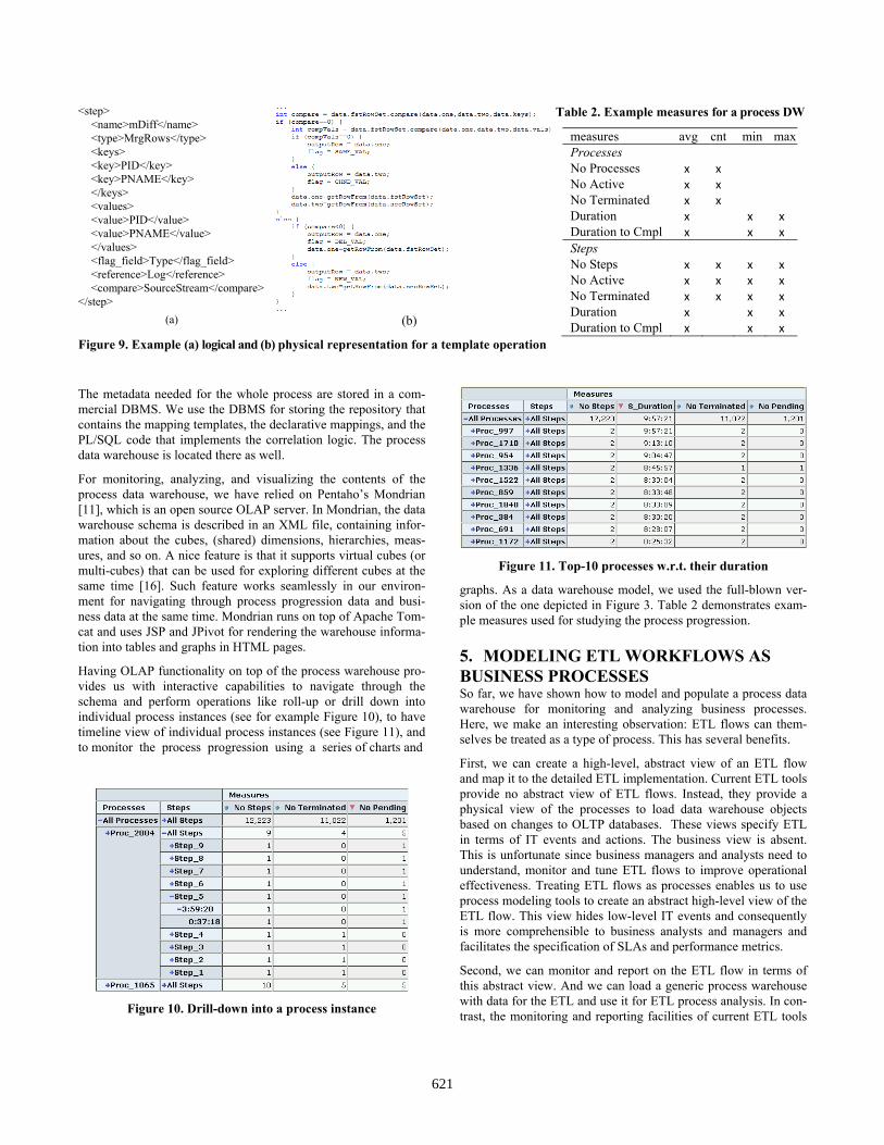
Having OLAP functionality on top of the process warehouse pro-vides us with interactive capabilities to navigate through the schema and perform operations like roll-up or drill down into individual process instances (see for example Figure 10), to have timeline view of individual process instances (see Figure 11), and to monitor the process progression using a series of charts and
Figure 10. Drill-down into a process instance
Figure 11. Top-10 processes w.r.t. their duration
graphs. As a data warehouse model, we used the full-blown ver-sion of the one depicted in Figure 3. Table 2 demonstrates exam-ple measures used for studying the process progression.
5. MODELING ETL WORKFLOWS AS BUSINESS PROCESSES So far, we have shown how to model and populate a process data warehouse for monitoring and analyzing business processes. Here, we make an interesting observation: ETL flows can them-selves be treated as a type of process. This has several benefits.
First, we can create a high-level, abstract view of an ETL flow and map it to the detailed ETL implementation. Current ETL tools provide no abstract view of ETL flows. Instead, they provide a physical view of the processes to load data warehouse objects based on changes to OLTP databases. These views specify ETL in terms of IT events and actions. The business view is absent. This is unfortunate since business managers and analysts need to understand, monitor and tune ETL flows to improve operational effectiveness. Treating ETL flows as processes enables us to use process modeling tools to create an abstract high-level view of the ETL flow. This view hides low-level IT events and consequently is more comprehensible to business analysts and managers and facilitates the specification of SLAs and performance metrics.
Second, we can monitor and report on the ETL flow in terms of this abstract view. And we can load a generic process warehouse with data for the ETL and use it for ETL process analysis. In con-trast, the monitoring and reporting facilities of current ETL tools
621

provide only a low-level view intended for ETL developers, but not suitable for business analysts.
In the rest, we sketch how to use the techniques we have de-scribed so far to model and analyze ETL flows.
Each ETL flow can be considered a separate business process. An operator in an ETL flow corresponds to a task (step) in a business process. A set of ETL flows with interdependencies (e.g., flow A must finish before flow B starts) could also be modeled as a high-er-level business process workflow.
We propose the use of an existing tool for business process mod-eling, such as HP BPI, to specify a high-level view of an ETL flow. Then, we can use correlation techniques as described earlier to link the abstract view to events in the ETL execution. We can trace the execution of an ETL flow by monitoring log and table activity. As with an arbitrary business process, these events are used to update “business data” for the ETL flow. The business data is then used to update the ETL process progression fact tables in the warehouse. The logical and physical mappings are generated from templates that are derived using declarative map-pings and correlation logic. By doing this, we obtain a real-time, business view of ETL processes that can be leveraged for moni-toring, analysis and reporting.
In order to track the ETL flow, we augment the ETL operators to emit step events to a separate log. The basic step events include operator start, operator end, operator error, operator checkpoint, and operator statistics but there may be operator-specific events as well. The step events can then be extracted and processed to update the generic process warehouse just as any other business process. An elegant means for augmenting the ETL operators is depicted in Figure 12. Although there is no standard representa-tion of ETL flows, in general, both the research and the commer-cial approaches use the same logical representation for ETL oper-ators: each transformation has one or more input and output schemata, a mapping among them, along with the operational semantics that describe its functionality. Our approach is to add one more level of abstraction, in which we consider one addition-al schema, called the event schema. The attributes of this schema represent the events previously mentioned.
Note that a major difference between conventional ETL and busi-ness processes is that ETL is batch-oriented. In ETL, pipeline parallelism is typically used to improve performance by streaming data among operators. Thus, many operators are active concur-rently. Business processes are event-oriented. Generally only one or a few actions are active concurrently and any single action is active only for processing a single event. Consequently, the active (or idle) time of an activity in a business process has a different meaning than the active time of an ETL operator. Similarly, the processing rate of an operator might be of interest in ETL but of less interest for a business process.
We note that as enterprises move toward operational business intelligence (BI), there will be reduced latency between OLTP events and warehouse loads. Consequently, we expect the batch size for ETL will shrink and, in the limit, perhaps be a single tuple. In other words, a stream-based approach using a workflow paradigm may be more appropriate for operational BI rather than today's conventional BI approach uses periodic batch loads.
Figure 12. An additional level of abstraction for ETL
Therefore, in the future, the batch-oriented vs. event-oriented difference may not be relevant.
Example. Consider the ETL flow that loads a purchase order to a warehouse order fact table. It might comprise three dependent ETL flows: (a) Extract: OLTP purchase order (PO) extract landing table; (b) Transform: extract landing table order land-ing table; (c) Load: order landing table load order fact table.
The Extract and Load flows are relatively simple and comprise a few ETL operators. However, the Transform flow would presum-ably be more complicated and include operators for validation checks, some surrogate key generation and retrieval, perhaps some banding and/or summarization. However, the business view could be as simple as Extract, Transform, Load. Alternatively, depending on business need, the Transform ETL flow could be viewed at a more detailed level, e.g., validation key lookup PO key generation. Of course, these steps could in turn be viewed at any even more detailed level if necessary, e.g., key lookup retrieves surrogate keys for a number of different dimensional tables.
Once the desired business view is established, correlation logic and declarative mappings can be used to convert the operator events into process progression data using mappings generated from the transformation language. The generic process warehouse can then be loaded and analysis and reporting can be performed on the ETL for the order fact table.
6. RELATED WORK The population of the data warehouses, so called the back stage of the data warehouse, has been studied in several research works during the last decade. The extract-transform-load (ETL) processes, which are responsible for this task, have two main challenges: the determination of their design and the optimization of their execution. For the first, several modeling solutions have been proposed at both the conceptual and the logical level [e.g., 10]. On the other hand, the existing commercial ETL tools only support the implementation of ETL flows given an existing de-sign. Regarding the optimization of ETL processes, despite its importance, less efforts have been proposed at both the logical [e.g., 18] and the physical [e.g., 21] level. More recently, several works have dealt with the novel trend of the (near) real-time data warehouse population, either by studying generic architectural issues [e.g., 22] or by proposing specialized operations for such cases [e.g., 13, 14, 20].
622

However, as far as we are aware, the issue of warehousing process data has not been studied earlier. In addition, the idea of leveraging business process models for representing ETL activi-ties and of populating a data warehouse with the metadata of their execution for analyzing their progression is novel as well. Any concepts stemming from the research on optimizing ETL processes (either traditional or real-time) are of great interest and can fit seamlessly in our approach.
There are some efforts sharing similar motives and techniques in the area of workflow analysis systems, e.g., Filenet [6]. Still, such systems provide a data warehouse model that depends on the process meta-model, as it is built into the workflow engine. In addition, there is no specific capability for collecting and aggre-gating source data that are not coming from the workflow engine. Finally, such systems do not support process abstraction, and it is not publicly known how they realize the ETL process.
Many research efforts have tackled the issue of automating the mapping generation [e.g., 7, 15]. Although, some of the proposed ideas can be considered in our approach as well, our work differs since it does not produce logical mappings according to user spe-cified correspondences. Instead, it captures correspondences that are part of the execution semantics of abstract process progression by factoring out commonalities derived from the predefined struc-ture and semantics of the process warehouse model and of the types of mappings specific to the process warehousing domain. We are not aware of any work done in this direction.
7. CONCLUSIONS In this paper, we have proposed a method for the automatic popu-lation of a process data warehouse. We have demonstrated how the whole approach can be realized in a near real-time fashion. We have presented an extensible and generic template mechanism that drives the ETL of stream events, using two-levels of map-pings that are applied in two-phases. We have presented a proof-of-concept that validates our approach. The feedback we have got from customers signifies that the process warehouse and the anal-ysis of process progression are of great interest, especially in business process outsourcing (BPO) environments. In addition, we have taken a further step, and shown that the same approach can be used for warehousing ETL execution data, which is useful for (a) representing ETL processes at the business level, (b) moni-toring ETL processes, and (c) analyzing results and statistics re-garding the execution of ETL processes. Finally, although we describe our approach in the context of process data warehousing, we believe that it can be generalized to generic real-time data warehousing scenarios in which incoming streams are captured, transformed, and integrated into a data warehouse.
For the future, we consider the following challenges. First, tuning the real-time mechanism is a topic for future work. Although the MeshJoin operator can handle 20k tuples per second, which is sufficient for BPO environments, we will explore how to scale these rates. We plan to incorporate our method into the HP Busi-ness Cockpit [4], a platform for intelligence business processes analysis and optimization. Finally, we will work further on the promising idea of representing ETL flows as business processes.
8. REFERENCES 1. BPI. HP Business Process Insight software. Available at:
http://www.managementsoftware.hp.com/products/bpi, 2008. 2. F. Casati, M. Castellanos, U. Dayal, M.C. Shan. A Metric Definition,
Computation & Reporting Model for Business Operations Analysis. In EDBT, 2006.
3. F. Casati, M. Castellanos, U. Dayal, N. Salazar. A Generic solution for Warehousing Business Process Data. In VLDB, pp. 1128-1137, 2007.
4. M. Castellanos, F. Casati, M.-C. Shan, U. Dayal. iBOM: A Platform for Intelligent Business Operation Management. In ICDE, pp. 1084-1095,
2005. 5. J.-P. Dittrich, B. Seeger, D. S. Taylor, P. Widmayer: Progressive
Merge Join: A Generic and Non-blocking Sort-based Join Algorithm. In VLDB, pp. 299-310, 2002.
6. Filenet. IBM FileNet Business Activity Monitor. Available at: http://www-01.ibm.com/software/data/content-management/filenet-business-activity-monitor/
7. L. M. Haas, M. A. Hernández, H. Ho, L. Popa, M. Roth. Clio Grows up: From Research Prototype to Industrial Tool. In SIGMOD, pp. 805-810, 2005.
8. W. Hong, M. Stonebraker. Optimization of Parallel Query Execution Plans in XPRS. In Distributed and Parallel Databases 1(1), pp. 9-32, 1993.
9. Kettle. Pentaho Data Integration. Available at: http://kettle.pentaho.org/, 2008.
10. R. Kimball, et al. The Data Warehouse Lifecycle Toolkit. John Wiley & Sons, 1998.
11. Mondrian. Pentaho’s Mondrian Project. Available at: http://mondrian.pentaho.org/, 2008.
12. Openadaptor. Available at: https://www.openadaptor.org/, 2008. 13. N. Polyzotis, S. Skiadopoulos, P. Vassiliadis, A. Simitsis, N.-E. Frant-
zell. Supporting Streaming Updates in an Active Data Warehouse. In ICDE, pp. 476-485, 2007.
14. N. Polyzotis, S. Skiadopoulos, P. Vassiliadis, A. Simitsis, N.-E. Frant-zell. Meshing Streaming Updates with Persistent Data in an Active Data Warehouse. In IEEE TKDE 20(7), pp. 976-991, 2008.
15. E. Rahm, P. A. Bernstein. A Survey of Approaches to Automatic Schema Matching. In VLDB J. 10(4), pp. 334-350, 2001.
16. A. Simitsis, A. Baid, Y. Sismanis, B. Reinwald. Multidimensional Content Exploration. In PVLDB 1(1), pp. 660-671, 2008.
17. A. Simitsis, D. Skoutas, M. Castellanos. Natural language reporting for ETL processes. In DOLAP, pp. 65-72, 2008.
18. A. Simitsis, P. Vassiliadis, T. K. Sellis. State-Space Optimization of ETL Workflows. In IEEE TKDE 17(10), pp. 1404-1419, 2005.
19. Y. Tao, M. L. Yiu, D. Papadias, M. Hadjieleftheriou, N. Mamoulis: RPJ: Producing Fast Join Results on Streams through Rate-based Op-timization. In SIGMOD, pp. 371-382, 2005.
20. C. Thomsen, T. B. Pedersen, W. Lehner. RiTE: Providing On-Demand Data for Right-Time Data Warehousing. In ICDE, pp. 456-465, 2008.
21. V. Tziovara, P. Vassiliadis, A. Simitsis. Deciding the Physical Imple-mentation of ETL Workflows. In DOLAP, pp. 49-56, 2007.
22. P. Vassiliadis, A. Simitsis. Near Real Time ETL. In Springer journal Annals of Information Systems, Volume 3, Special issue on "New Trends in Data Warehousing and Data Analysis", 2008.
23. Velocity. The Apache Velocity Project. Available at: http://velocity.apache.org/, 2008.
24. T. Urhan, M. J. Franklin: XJoin: A Reactively-Scheduled Pipelined Join Operator. In IEEE Data Eng. Bull. 23(2), pp. 27-33, 2000.
25. WS-BPEL Version 2.0, Oasis.. Available at: http://docs.oasis-open.org/wsbpel/2.0/wsbpel-v2.0.pdf
623