automatic voltage regulator compatible with leroy … manual.pdf · automatic voltage regulator...
TRANSCRIPT
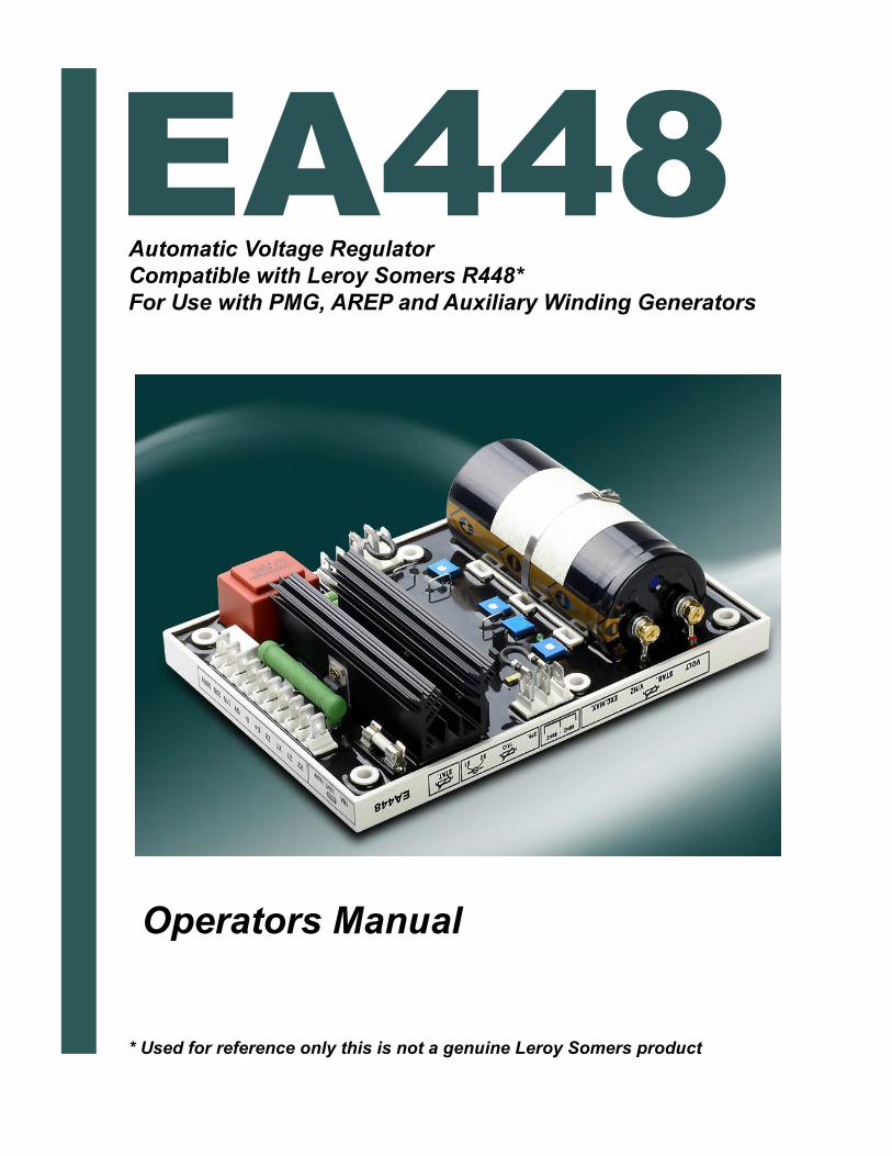
Automatic Voltage Regulator
Compatible with Leroy Somers R448*
For Use with PMG, AREP and Auxiliary Winding Generators
* Used for reference only this is not a genuine Leroy Somers product
Operators Manual
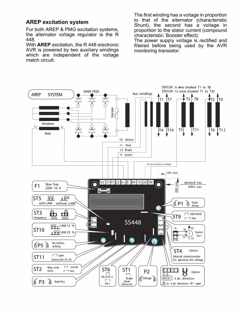
SPECIFICATIONS Normal AVR supply power: 2 auxiliary windings (X1, X2, and Z, Z2)
Shunt supply : 150V - 50/60Hz
Rated overload current: 10A, 10s.
Electronic built-in (overload, short circuit, and loss of sensing) protection: If excitation current raises over 10 Amps for more then 10 seconds, excitation current will drops automatically to about 1A.
To reset AVR protection, generator must be stopped (or by cutting supply voltage to the AVR).
Protection of power inputs by fuses F1
Voltage sensing: 5VA insulated transformer with input voltage taps at:
Terminals 0-110V = 95 to 140V
Terminals 0-220 V = 170 to 260 V
Terminals 0-380 V = 340 to 520V
Output Voltage adjustment by using pot P2
Other sensing voltages by using an adapting other
transformers
Current sensing (parallel operation) CT 2.5 VA class 1 secondary current xxx/1 (optional).
Adjustment of quadrature droop with pot P1
Under-speed (U/F) and LAM protection: for knee frequency adjustable use P4.
Excitation over current adjustment use P5: 4.5 to 10A
For 50/60 Hz (U/F) selection use jumper ST3.
Load acceptance module LAM is suppressed by cutting wire marked ST5
LAM (Load Acceptance Module) function.
When applying a step load to the generator, the
rotational speed (frequency) of the genset drops. If the speed is below the preset frequency, the "LAM" circuits drops the voltage about 15% and this way reducing the effective step to about 25%, as long as the speed has not recovered to normal values.
The "LAM" is used either to reduce the speed drop of the engine, during the step load, or to increase
the applicable step load for the same speed variation (turbo charged engines) so the engine can recover normal speed quickly.
To prevent voltage oscillations, the frequency threshold must be adjusted about 2 Hz below the lowest
frequency in normal operation.
Optional items for use with the AVR
CT for parallel operation with other generators
Remote voltage adjusting potentiometer 470 ohm .3W
(*) giving an adjustment range of +/- 5% (centering of the range by using internal P2 potentiometer). Remove wire ST4 to connect external potentiometer.
Three phase sensing available by using additional modulo Model R 730:200 to 500V. Cut ST1 to connect this module.
Generator output voltage is adjusted by using the voltage adjustment potentiometer on the AVR
Power factor regulator (2nd function) and voltage
equalization before paralleling with the mains (3rd function)
CT xxx/1 A. 5VA CL1
Module R 724: 2 functions.
Module R 725 A: 3 functions.
EMI suppression
(*)Note: For a wider voltage adjustment range and 1 k ohm/3W pot may be used.
The R 730 module is not compatible with paralleling.
Special applications
Field de-energizing
Cutting excitation current is accomplished by
switching off the supply power to AVR (1 lead on each auxiliary winding)
Contacts capacity: 10A. 250V AC
This is the same connection used to reset internal protection of AVR.
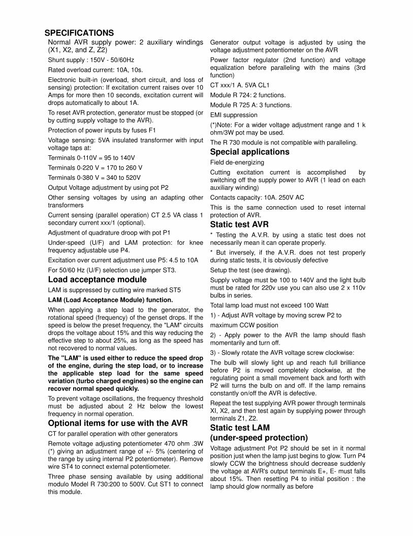
Static test AVR * Testing the A.V.R. by using a static test does not
necessarily mean it can operate properly.
* But inversely, if the A.V.R. does not test properly during static tests, it is obviously defective
Setup the test (see drawing).
Supply voltage must be 100 to 140V and the light bulb must be rated for 220v use you can also use 2 x 110v bulbs in series.
Total lamp load must not exceed 100 Watt
1) - Adjust AVR voltage by moving screw P2 to
maximum CCW position
2) - Apply power to the AVR the lamp should flash
momentarily and turn off.
3) - Slowly rotate the AVR voltage screw clockwise:
The bulb will slowly light up and reach full brilliance before P2 is moved completely clockwise, at the regulating point a small movement back and forth with P2 will turns the bulb on and off. If the lamp remains
constantly on/off the AVR is defective.
Repeat the test supplying AVR power through terminals XI, X2, and then test again by supplying power through terminals Z1, Z2.
Static test LAM
(under-speed protection) Voltage adjustment Pot P2 should be set in it normal position just when the lamp just begins to glow. Turn P4
slowly CCW the brightness should decrease suddenly the voltage at AVR's output terminals E+, E- must falls about 15%. Then resetting P4 to initial position : the lamp should glow normally as before

Adjustment procedure a) Initial setting of potentiometers
- P2 VOLTAGE: lowest fully CCW.
- P3 STABILITY: middle position.
- PI QUADRATURE VOLTAGE DROP : fully CCW
- P5 EXCITATION CURRENT LIMIT: to be adjusted only if necessary maximum fully CW.
- Remote voltage trimmer Rhe - 470 OHM (jumper ST4 removed): middle position.
b) Connect one analog (needle type) voltmeter cal. 50V D.C. across E+, E-terminals and another (300V-500V or
1000V) A.C. across the alternator output terminals.
c) Make sure that the 50/60 Hz link is correctly connected
d) (P2) potentiometer must be set maximum anti-clockwise
e) (P4) (V/Hz) must be set maximum clockwise
f) (P3) (Stability) has to be adjusted maximum
clockwise -1/3.
g) Start and adjust the engine speed corresponding to 48Hz for 50 Hz (nominal) or 58 for 60 Hz.
h) Adjust output voltage with (P2) to the required value
- rated voltage UN if generator operates alone
(for example 400V)
-or UN+2 to 4% for parallel operation with CT
(i.e. 410V - see below)
If voltage is unstable, adjust (P3) (try in both directions), noting voltage across E+, E- (approx.1OV dc) The fastest recovery time may be achieved when
(P3) is set close to the limit of instability. If there is no stable position try adjustment again after having cut or reconnecting link ST2 (normal / fast).
i) Turn (P4) anticlockwise until the voltage drops about 15%
j) Modify engine speed around 48 or 58 Hz in order to check the LAM voltage drop (~ 15%).
k) Readjust speed of genset to its normal no-load level
ADJUSTMENTS IN
PARALLEL OPERATION
Note: Preliminary to any adjustment on the AVR, make sure that engine speeds are similar.
l) Presetting for parallel operation (with CT connected to
terminals S1 ,S2 of terminal strip J2)
- Potentiometer P1 (Voltage droop) in middle position. Switch on the rated load (P.F. 0.8 inductive). The output voltage should drop 2% to 3%. If voltage rises, reverse
the 2 leads from the CT.
m) No load voltages must be identical on all gensets working together and in parallel.
- Synchronize and parallel the gensets together.
- By adjusting engine speed, reduce power exchange, to 0 KW
- By adjusting voltage pot (P2 or Rhe) on one of the
machines try to cancel (or minimize) circulating currents.
- Do not change voltage adjustments.
n) Switch on the load (adjustments cannot be made if there is no reactive load).
- By adjusting speed, balance the KW (proportionally to the rated powers of each genset).
- By adjusting voltage droop with pot. P1, balance the output currents.
Adjustment of maximum excitation current(Excitation ceiling)
- Static adjustment of excitation current limitation, potentiometer P5 (factory adjustment: 10 A, fuse caliber: 10A-10seconds).
The factory adjustment corresponds to the excitation current for a sustained 3 phase short circuit, of about 3 times the rated current, unless otherwise specified(*)
It is possible to reduce the maximum excitation level by a static method which is safer for the alternators and the network.
Disconnect the supply leads (XI X2, Z1, Z2) and sensing leads (0-110-220-380) on the AVR. Connect the supply as shown (XI, X2, 0,110V). Connect an ammeter (10A, dc) in series with the exciter field. Turn P5 fully CCW. Switch on the supply. If there is no output current from AVR, turn P2 (voltage) clockwise until
ammeter indicates a stabilized current.
Switch the supply off, then on again. Turn P5 clockwise until the required current is obtained in the exciter field,
(limit to 10A)
Checking internal protection:
Switch off (B): the excitation current must rise to the pre-set high level, and remain at this level for a period of more than 10 seconds, than fall to less than 1A.
To reset, switch off the supply by opening switch (A).
Note: After having adjusted the excitation current
limitation
(*): In many countries short-circuit current equal to 3 times IN is obligatory in order to allow selective tripping of circuit breakers.

S23phi n
3ph in
P2
VR1k
S1
VRVRP3
P4
P5
60HZ
380V
E-
0V
220V
110V
Z2
X1
E+
Z1
X2
50HZ
Frequency
VlotageSS448
(Supply 50/60Hz)
220VP<100W
VM
300Vdc
MainsLED
S2S2
LED
ST7
3phin
3ph in
ST1
P2
1k
S1
VRVR S1
ST2P3
ST6
P4J2
50HZ
P5
60HZ
J1 Z1
380V
P1
E-
0V
220V
110V
Z2
X1
E+
380V
E-
110V220V
0V
X1Z2E+
Z1
X2
Fuse 10A
X2
ST3
ST4
Static test AVR
Excite eld ~6 ohm
LED
Excit max
Voltage
3ph in
3phin
S1VR1 k
S 2
60HZ
P5
P2
P4
P3
VRVR
SS448
50HZ
X2
220V
380V
110V
0V
Z2
E+
E-
Z1
X1
(Supply 50/60Hz)
A
Mains
A
B
Adjustment of maximum excitation current


Set according to voltage
11 Red
9 Green
7.5MF
U
W
StatorC.T.
XX/1AR
S
T
Armature
Exciter field
200VAC max 50 to 500 Hz
PMG
380V
X2
Z1
X1
Z2
E+
E-
OV
110V220V
S1
S2
Fuse 10A
60Hz50Hz
AV
R E
A4
48
EXT VR 1k Ohm
480/277v
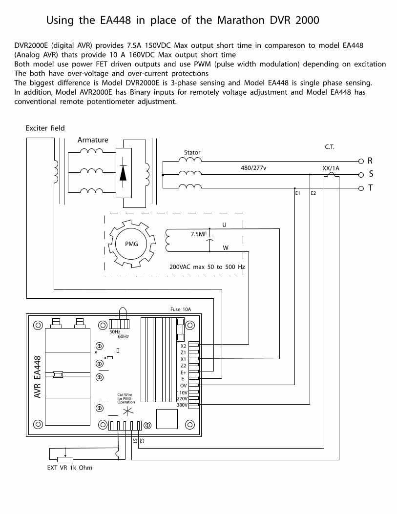
Using the EA448 in place of the Marathon DVR 2000
E1 E2
DVR2000E (digital AVR) provides 7.5A 150VDC Max output short time in compareson to model EA448
(Analog AVR) thats provide 10 A 160VDC Max output short time
Both model use power FET driven outputs and use PWM (pulse width modulation) depending on excitation
The both have over-voltage and over-current protections
The biggest difference is Model DVR2000E is 3-phase sensing and Model EA448 is single phase sensing.
In addition, Model AVR2000E has Binary inputs for remotely voltage adjustment and Model EA448 has
conventional remote potentiometer adjustment.