automatic transfer switch - electric generators direct · automatic transfer switch operation and...
TRANSCRIPT
Automatic Transfer Switch
Operation andInstallation
Model:
RXT100--400 Amp Automatic Transfer Switches
For use with Kohlerr generator sets equipped withRDC2 or DC2 generator/transfer switch controllers
TP-6807 1/16d

TP-6807 1/162
Product Identification Information
Product identification numbers determine service parts.Record the product identification numbers in the spacesbelow immediately after unpacking the products so thatthe numbers are readily available for future reference.Record field-installed kit numbers after installing thekits.
Transfer Switch Identification Numbers
Record the product identification numbers from thetransfer switch nameplate.
Model Designation
Serial Number

Table of Contents
TP-6807 1/16 Table of Contents 3
Product Identification Information 2. . . . . . . . . . . . . . . . . . . . . . . . . . . . . . . . . . . . . . . . . . . . . . . . . . . . . . . . . . . . .
Safety Precautions and Instructions 5. . . . . . . . . . . . . . . . . . . . . . . . . . . . . . . . . . . . . . . . . . . . . . . . . . . . . . . . .
Introduction 7. . . . . . . . . . . . . . . . . . . . . . . . . . . . . . . . . . . . . . . . . . . . . . . . . . . . . . . . . . . . . . . . . . . . . . . . . . . . . . .List of Related Literature 8. . . . . . . . . . . . . . . . . . . . . . . . . . . . . . . . . . . . . . . . . . . . . . . . . . . . .Nameplate 8. . . . . . . . . . . . . . . . . . . . . . . . . . . . . . . . . . . . . . . . . . . . . . . . . . . . . . . . . . . . . . . . .Model Designation 9. . . . . . . . . . . . . . . . . . . . . . . . . . . . . . . . . . . . . . . . . . . . . . . . . . . . . . . . . .
Service Assistance 10. . . . . . . . . . . . . . . . . . . . . . . . . . . . . . . . . . . . . . . . . . . . . . . . . . . . . . . . . . . . . . . . . . . . . . . . .
Section 1 Description 11. . . . . . . . . . . . . . . . . . . . . . . . . . . . . . . . . . . . . . . . . . . . . . . . . . . . . . . . . . . . . . . . . . . . . .1.1 Transfer Switch Description 11. . . . . . . . . . . . . . . . . . . . . . . . . . . . . . . . . . . . . . . . . . . . .1.2 Service Entrance Models 11. . . . . . . . . . . . . . . . . . . . . . . . . . . . . . . . . . . . . . . . . . . . . . .1.3 Load Centers 11. . . . . . . . . . . . . . . . . . . . . . . . . . . . . . . . . . . . . . . . . . . . . . . . . . . . . . . . .1.4 Controller Interface Board 12. . . . . . . . . . . . . . . . . . . . . . . . . . . . . . . . . . . . . . . . . . . . . . .
1.4.1 Standard Interface Board 12. . . . . . . . . . . . . . . . . . . . . . . . . . . . . . . . . . . . . . .1.4.2 Combined Interface/Load Management Board 12. . . . . . . . . . . . . . . . . . . . .
1.5 Optional Status Indicator Panels 14. . . . . . . . . . . . . . . . . . . . . . . . . . . . . . . . . . . . . . . . .1.5.1 Standard Status Indicator Panel 14. . . . . . . . . . . . . . . . . . . . . . . . . . . . . . . . .1.5.2 Status Indicator Panel for Combined Interface/Load Management Board . .
14
Section 2 Installation 15. . . . . . . . . . . . . . . . . . . . . . . . . . . . . . . . . . . . . . . . . . . . . . . . . . . . . . . . . . . . . . . . . . . . . .2.1 Introduction 15. . . . . . . . . . . . . . . . . . . . . . . . . . . . . . . . . . . . . . . . . . . . . . . . . . . . . . . . . . .2.2 Receipt of Unit 15. . . . . . . . . . . . . . . . . . . . . . . . . . . . . . . . . . . . . . . . . . . . . . . . . . . . . . . .
2.2.1 Inspection 15. . . . . . . . . . . . . . . . . . . . . . . . . . . . . . . . . . . . . . . . . . . . . . . . . . . .2.2.2 Storage 15. . . . . . . . . . . . . . . . . . . . . . . . . . . . . . . . . . . . . . . . . . . . . . . . . . . . . .2.2.3 Unpacking 15. . . . . . . . . . . . . . . . . . . . . . . . . . . . . . . . . . . . . . . . . . . . . . . . . . . .2.2.4 Lifting 15. . . . . . . . . . . . . . . . . . . . . . . . . . . . . . . . . . . . . . . . . . . . . . . . . . . . . . . .
2.3 Installation 16. . . . . . . . . . . . . . . . . . . . . . . . . . . . . . . . . . . . . . . . . . . . . . . . . . . . . . . . . . . .2.4 Manual Operation Check 17. . . . . . . . . . . . . . . . . . . . . . . . . . . . . . . . . . . . . . . . . . . . . . .
2.4.1 Manual Operation Procedure 1 17. . . . . . . . . . . . . . . . . . . . . . . . . . . . . . . . . .2.4.2 Manual Operation Procedure 2 17. . . . . . . . . . . . . . . . . . . . . . . . . . . . . . . . . .
2.5 Electrical Wiring 18. . . . . . . . . . . . . . . . . . . . . . . . . . . . . . . . . . . . . . . . . . . . . . . . . . . . . . .2.5.1 Load Center Circuit Breakers 19. . . . . . . . . . . . . . . . . . . . . . . . . . . . . . . . . . . .2.5.2 AC Power Connections 19. . . . . . . . . . . . . . . . . . . . . . . . . . . . . . . . . . . . . . . . .2.5.3 Neutral Connection 19. . . . . . . . . . . . . . . . . . . . . . . . . . . . . . . . . . . . . . . . . . . .2.5.4 Neutral Bonding Jumper, Service Entrance Models 19. . . . . . . . . . . . . . . . .2.5.5 Engine Start Function 19. . . . . . . . . . . . . . . . . . . . . . . . . . . . . . . . . . . . . . . . . .
2.6 Interface Module Connection 20. . . . . . . . . . . . . . . . . . . . . . . . . . . . . . . . . . . . . . . . . . . .2.7 Combined Interface/Load Management Board 22. . . . . . . . . . . . . . . . . . . . . . . . . . . . .
2.7.1 Relay Modules 22. . . . . . . . . . . . . . . . . . . . . . . . . . . . . . . . . . . . . . . . . . . . . . . .2.7.2 HVAC Loads 22. . . . . . . . . . . . . . . . . . . . . . . . . . . . . . . . . . . . . . . . . . . . . . . . . .2.7.3 Load Add/Shed Priority 22. . . . . . . . . . . . . . . . . . . . . . . . . . . . . . . . . . . . . . . . .2.7.4 Current Transformers (CTs) 23. . . . . . . . . . . . . . . . . . . . . . . . . . . . . . . . . . . . .2.7.5 Connection Procedure 23. . . . . . . . . . . . . . . . . . . . . . . . . . . . . . . . . . . . . . . . . .
2.8 Load Control Module (LCM) 26. . . . . . . . . . . . . . . . . . . . . . . . . . . . . . . . . . . . . . . . . . . . .2.8.1 LCM with Standard Interface Board 26. . . . . . . . . . . . . . . . . . . . . . . . . . . . . .2.8.2 LCM with Combined Interface Board 26. . . . . . . . . . . . . . . . . . . . . . . . . . . . .
2.9 Optional Load Control Connection 28. . . . . . . . . . . . . . . . . . . . . . . . . . . . . . . . . . . . . . .2.10 Accessory Module Connections 28. . . . . . . . . . . . . . . . . . . . . . . . . . . . . . . . . . . . . . . . .2.11 Test and Exercise 28. . . . . . . . . . . . . . . . . . . . . . . . . . . . . . . . . . . . . . . . . . . . . . . . . . . . . .2.12 Warranty Registration 28. . . . . . . . . . . . . . . . . . . . . . . . . . . . . . . . . . . . . . . . . . . . . . . . . .

Table of Contents, continued
TP-6807 1/16Table of Contents4
Section 3 Operation 29. . . . . . . . . . . . . . . . . . . . . . . . . . . . . . . . . . . . . . . . . . . . . . . . . . . . . . . . . . . . . . . . . . . . . . . .3.1 Model RXT Transfer Switch Operation 29. . . . . . . . . . . . . . . . . . . . . . . . . . . . . . . . . . . .3.2 Source Availability 29. . . . . . . . . . . . . . . . . . . . . . . . . . . . . . . . . . . . . . . . . . . . . . . . . . . . .3.3 ATS Control Sequence of Operation 29. . . . . . . . . . . . . . . . . . . . . . . . . . . . . . . . . . . . . .3.4 Load Management Operation 29. . . . . . . . . . . . . . . . . . . . . . . . . . . . . . . . . . . . . . . . . . .
3.4.1 Power Loads 30. . . . . . . . . . . . . . . . . . . . . . . . . . . . . . . . . . . . . . . . . . . . . . . . . .3.4.2 HVAC Loads 30. . . . . . . . . . . . . . . . . . . . . . . . . . . . . . . . . . . . . . . . . . . . . . . . . .3.4.3 Load Add/Shed Priority 30. . . . . . . . . . . . . . . . . . . . . . . . . . . . . . . . . . . . . . . . .3.4.4 Status Indicator and Test Button 30. . . . . . . . . . . . . . . . . . . . . . . . . . . . . . . . .
3.5 Load Management Theory of Operation 31. . . . . . . . . . . . . . . . . . . . . . . . . . . . . . . . . .3.5.1 Load Add 31. . . . . . . . . . . . . . . . . . . . . . . . . . . . . . . . . . . . . . . . . . . . . . . . . . . . .3.5.2 Load Shed 32. . . . . . . . . . . . . . . . . . . . . . . . . . . . . . . . . . . . . . . . . . . . . . . . . . . .3.5.3 Overload Shed 32. . . . . . . . . . . . . . . . . . . . . . . . . . . . . . . . . . . . . . . . . . . . . . . .3.5.4 Under Frequency Shed 32. . . . . . . . . . . . . . . . . . . . . . . . . . . . . . . . . . . . . . . . .3.5.5 Load Shed Acceleration 33. . . . . . . . . . . . . . . . . . . . . . . . . . . . . . . . . . . . . . . .3.5.6 Changing Settings 33. . . . . . . . . . . . . . . . . . . . . . . . . . . . . . . . . . . . . . . . . . . . .
3.6 Time Delays 34. . . . . . . . . . . . . . . . . . . . . . . . . . . . . . . . . . . . . . . . . . . . . . . . . . . . . . . . . .3.7 Load Control Time Delay 34. . . . . . . . . . . . . . . . . . . . . . . . . . . . . . . . . . . . . . . . . . . . . . .
Section 4 Service Disconnect, SE Model 35. . . . . . . . . . . . . . . . . . . . . . . . . . . . . . . . . . . . . . . . . . . . . . . . . . . .4.1 Service Disconnect Procedure 35. . . . . . . . . . . . . . . . . . . . . . . . . . . . . . . . . . . . . . . . . . .4.2 Source Circuit Breaker Reset 36. . . . . . . . . . . . . . . . . . . . . . . . . . . . . . . . . . . . . . . . . . . .
Section 5 Scheduled Maintenance 37. . . . . . . . . . . . . . . . . . . . . . . . . . . . . . . . . . . . . . . . . . . . . . . . . . . . . . . . . .5.1 Introduction 37. . . . . . . . . . . . . . . . . . . . . . . . . . . . . . . . . . . . . . . . . . . . . . . . . . . . . . . . . . .5.2 Testing 38. . . . . . . . . . . . . . . . . . . . . . . . . . . . . . . . . . . . . . . . . . . . . . . . . . . . . . . . . . . . . . .
5.2.1 Weekly Generator Set Exercise 38. . . . . . . . . . . . . . . . . . . . . . . . . . . . . . . . . .5.2.2 Monthly Automatic Control System Test 38. . . . . . . . . . . . . . . . . . . . . . . . . . .
5.3 Inspection and Service 38. . . . . . . . . . . . . . . . . . . . . . . . . . . . . . . . . . . . . . . . . . . . . . . . .5.3.1 General Inspection 38. . . . . . . . . . . . . . . . . . . . . . . . . . . . . . . . . . . . . . . . . . . . .5.3.2 Other Inspections and Service 38. . . . . . . . . . . . . . . . . . . . . . . . . . . . . . . . . . .
5.4 Service Schedule 39. . . . . . . . . . . . . . . . . . . . . . . . . . . . . . . . . . . . . . . . . . . . . . . . . . . . . .
Section 6 Diagrams and Drawings 41. . . . . . . . . . . . . . . . . . . . . . . . . . . . . . . . . . . . . . . . . . . . . . . . . . . . . . . . . .
Appendix A Abbreviations 77. . . . . . . . . . . . . . . . . . . . . . . . . . . . . . . . . . . . . . . . . . . . . . . . . . . . . . . . . . . . . . . .
TP-6807 1/16 5Safety Precautions and Instructions
Safety Precautions and Instructions
IMPORTANTSAFETY INSTRUCTIONS.Electromechanical equipment,including generator sets, transferswitches, switchgear, and accessories,can cause bodily harm and poselife-threatening danger whenimproperly installed, operated, ormaintained. To prevent accidents beaware of potential dangers and actsafely. Read and follow all safetyprecautions and instructions. SAVETHESE INSTRUCTIONS.
Thismanual has several types of safetyprecautions and instructions: Danger,Warning, Caution, and Notice.
DANGER
Danger indicates the presence of ahazard that will cause severepersonal injury, death, orsubstantialproperty damage.
WARNING
Warning indicates the presence of ahazard that can cause severepersonal injury, death, orsubstantialproperty damage.
CAUTION
Caution indicates the presence of ahazard that will or can cause minorpersonal injury or property damage.
NOTICENotice communicates installation,operation, or maintenance informationthat is safety related but not hazardrelated.
Safety decals affixed to the equipmentin prominent places alert the operatoror service technician to potentialhazards and explain how to act safely.The decals are shown throughout thispublication to improve operatorrecognition. Replace missing ordamaged decals.
Accidental Starting
Accidental starting.Can cause severe injury or death.
Disconnect the battery cables beforeworking on the generator set.Remove the negative (--) lead firstwhen disconnecting the battery.Reconnect the negative (--) lead lastwhen reconnecting the battery.
WARNING
Disabling the generator set.Accidental starting can causesevere injury or death. Beforeworking on the generator set orequipment connected to the set,disable the generator set as follows:(1) Press the generator set off/resetbutton to shut down the generator set.(2) Disconnect the power to the batterycharger, if equipped. (3) Remove thebattery cables, negative (--) lead first.Reconnect the negative (--) lead lastwhen reconnecting the battery. Followthese precautions to prevent thestarting of the generator set by theremote start/stop switch.
Hazardous Voltage/Moving Parts
Hazardous voltage.Will cause severe injury or death.
Disconnect all power sources beforeopening the enclosure.
DANGER
Hazardous voltage.Will cause severe injury or death.
Only authorized personnel shouldopen the enclosure.
DANGER
Hazardous voltage.Will cause severe injury or death.
This equipment must be installed andserviced by qualified electricalpersonnel.
DANGER
Grounding electrical equipment.Hazardous voltage can causesevere injury or death. Electrocutionis possible whenever electricity ispresent. Ensure you comply with allapplicable codes and standards.Electrically ground the generator set,transfer switch, and related equipmentand electrical circuits. Turn off themaincircuit breakers of all power sourcesbefore servicing the equipment. Nevercontact electrical leads or applianceswhen standing in water or on wetground because these conditionsincrease the risk of electrocution.
Short circuits. Hazardousvoltage/current can cause severeinjury or death. Short circuits cancause bodily injury and/or equipmentdamage. Do not contact electricalconnections with tools or jewelry whilemaking adjustments or repairs.Remove all jewelry before servicing theequipment.

TP-6807 1/166 Safety Precautions and Instructions
Making line or auxiliaryconnections. Hazardous voltagecan cause severe injury or death. Toprevent electrical shock deenergize thenormal power source before makingany line or auxiliary connections.
Servicing the transfer switch.Hazardous voltage can causesevere injuryor death. Deenergizeallpower sources before servicing. Turnoff the main circuit breakers of alltransfer switch power sources anddisable all generator sets as follows:(1) Press the generator set off/resetbutton to shut down the generator set.(2) Disconnect power to all batterychargers. (3) Disconnect all batterycables, negative (--) leads first.Reconnect negative (--) leads lastwhenreconnecting the battery cables afterservicing. Follow these precautions toprevent the starting of generator setsby an automatic transfer switch, remotestart/stop switch, or engine startcommand from a remote computer.Before servicing any componentsinside the enclosure: (1) Remove alljewelry. (2) Stand on a dry, approvedelectrically insulated mat. (3) Testcircuits with a voltmeter to verify thatthey are deenergized.
Heavy Equipment
Unbalanced weight.Improper lifting can cause severeinjury or death and equipmentdamage.
Use adequate lifting capacity.Never leave the transfer switchstanding upright unless it is securelybolted in place or stabilized.
WARNING
NoticeNOTICE
Foreign material contamination.Cover the transfer switch duringinstallation to keep dirt, grit, metal drillchips, and other debris out of thecomponents. Cover the solenoidmechanism during installation. Afterinstallation, use the manual operatinghandle to cycle the contactor to verifythat it operates freely. Do not use ascrewdriver to force the contactormechanism.
NOTICEElectrostatic discharge damage.Electrostatic discharge (ESD)damages electronic circuit boards.Prevent electrostatic dischargedamage by wearing an approvedgrounding wrist strap when handlingelectronic circuit boards or integratedcircuits. An approved grounding wriststrap provides a high resistance (about1 megohm), not a direct short, toground.

TP-6807 1/16 7Introduction
Introduction
This manual provides operation and installationinstructions for Kohlerr Model RXT automatic transferswitches. See Figure 2 for typical Model RXT transferswitches.
Model RXT transfer switches operate only with Kohlerrgenerator sets equipped with the RDC2 or DC2generator/transfer switch controller. See Figure 1 orFigure 3 for controller identification. The transfer switchis equipped with either a standard interface board or acombined interface/ load management board. Theinterface board communicates with the RDC2 or DC2controller on the generator set.
Information in this publication represents data availableat the time of print. Kohler Co. reserves the right tochange this literature and the products representedwithout notice and without any obligation or liabilitywhatsoever.
Read this manual and carefully follow all proceduresand safety precautions to ensure proper equipmentoperation and to avoid bodily injury. Readand follow theSafety Precautions and Instructions section at thebeginning of this manual. Keep this manual with theequipment for future reference.
The equipment service requirements are very importantto safe and efficient operation. Inspect parts often andperform required service at the prescribed intervals.Obtain service from an authorized service distributor/dealer to keep equipment in top condition.
GM77569
RDC2 DC2
Figure 1 Original (green-board) RDC2 and DC2Generator/ Transfer Switch Controllers(mounted on the generator set)
Figure 2 Typical Model RXT Transfer Switches(shown with optional status indicators)
RDC2 DC2GM89864
Figure 3 Revised (red-board) RDC2 and DC2Generator/ Transfer Switch Controllers(mounted on the generator set)
TP-6807 1/168 Introduction
List of Related Literature
Figure 4 identifies related literature available for theautomatic transfer switches and accessories covered inthis manual. Only trained and qualified personnelshould install or service the transfer switch andaccessories.
Literature Type Part Number
Specification Sheet, Model RXT G11-140
Service and Parts Manual, Model RXT TP-6808
Operation Manual,SiteTecht Software TP-6701
Installation Instructions,Status Indicator TT--1585
Installation Instructions,Load Shed Kit TT-1609
Installation Instructions,Power Relay Module TT-1646
Figure 4 Related Literature
Nameplate
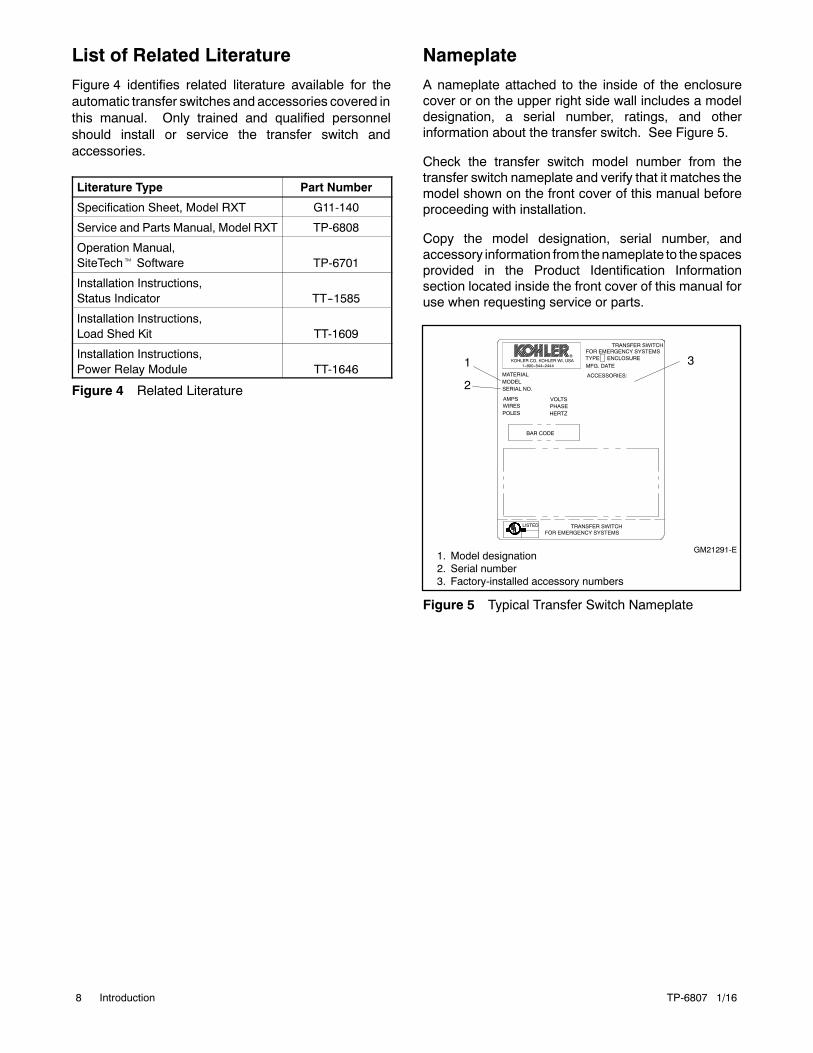
A nameplate attached to the inside of the enclosurecover or on the upper right side wall includes a modeldesignation, a serial number, ratings, and otherinformation about the transfer switch. See Figure 5.
Check the transfer switch model number from thetransfer switch nameplate and verify that it matches themodel shown on the front cover of this manual beforeproceeding with installation.
Copy the model designation, serial number, andaccessory information from thenameplate to thespacesprovided in the Product Identification Informationsection located inside the front cover of this manual foruse when requesting service or parts.
TRANSFER SWITCH
GM21291-E
1
2
3
1. Model designation2. Serial number3. Factory-installed accessory numbers
MATERIAL
FOR EMERGENCY SYSTEMSTRANSFER SWITCH
TYPE ENCLOSUREMFG. DATE
POLESWIRESAMPS
HERTZ
BAR CODE
PHASEVOLTS
SERIAL NO.MODEL
ACCESSORIES:
FOR EMERGENCY SYSTEMSLISTED
R
Figure 5 Typical Transfer Switch Nameplate

TP-6807 1/16 9Introduction
Model Designation
Figure 6 explains the model designation.
ModelRXT: Kohler Automatic Transfer Switch
ControlsJ: Interface board (standard or combined) for RDC2/DC2Controller
Number of Poles/Wires
Enclosure
ConnectionsA: No load centerB: With load center (100 amp single-phase only)ASE: Service entrance ratedCSE: Service entrance rated with CSA certification
(100/150/200 amp models only)
C: 208 Volts/60 Hz (3-phase only)F: 240 Volts/60 HzM: 480 Volts/60 Hz (3-phase only)
Voltage/Frequency
N: 2-pole, 3-wire, solid neutral (120/240 V only)T: 3-pole, 4-wire, solid neutralV: 4-pole, 4-wire, switched neutral
C: NEMA 3R
Model Controls Voltage Poles Enclosure Current Rating Connections
Current Rating: Numbers indicate the current ratingof the switch in amperes:
Record the transfer switch model designation in the boxes. The transfer switch model designation defines ratingsand characteristics as explained below.
Sample Model Designation: RXT-JFNC-0200A
01000150
02000300
0400
Note: GM85273-SA_ is a 100 amp single-phase model with a 12-circuit load center and NEMA 1 enclosure.
Figure 6 Model Designation

TP-6807 1/1610 Service Assistance
Service Assistance
For professional advice on generator set powerrequirementsandconscientiousservice, pleasecontactyour nearest Kohler distributor or dealer.
D Consult the Yellow Pages under the headingGenerators—Electric.
D Visit the Kohler Power Systems website atKOHLERPower.com.
D Look at the labels and decals on your Kohler productor review the appropriate literature or documentsincluded with the product.
D Call toll free in the US and Canada 1-800-544-2444.
D Outside theUSandCanada, call the nearest regionaloffice.
Headquarters Europe, Middle East, Africa(EMEA)Kohler Power Systems Netherlands B.V.Kristallaan 14761 ZC ZevenbergenThe NetherlandsPhone: (31) 168 331630Fax: (31) 168 331631
Asia PacificPower Systems Asia Pacific Regional OfficeSingapore, Republic of SingaporePhone: (65) 6264-6422Fax: (65) 6264-6455
ChinaNorth China Regional Office, BeijingPhone: (86) 10 6518 7950
(86) 10 6518 7951(86) 10 6518 7952
Fax: (86) 10 6518 7955
East China Regional Office, ShanghaiPhone: (86) 21 6288 0500Fax: (86) 21 6288 0550
India, Bangladesh, Sri LankaIndia Regional OfficeBangalore, IndiaPhone: (91) 80 3366208
(91) 80 3366231Fax: (91) 80 3315972
Japan, KoreaNorth Asia Regional OfficeTokyo, JapanPhone: (813) 3440-4515Fax: (813) 3440-2727
Latin AmericaLatin America Regional OfficeLakeland, Florida, USAPhone: (863) 619-7568Fax: (863) 701-7131

TP-6807 1/16 11Section 1 Description
Section 1 Description
1.1 Transfer Switch Description
An automatic transfer switch (ATS) transfers electricalloads from a normal source of electrical power to anemergency source when the normal source voltage orfrequency falls below an acceptable level. The normalsource is typically utility power. The emergency sourceis usually a generator set.
Model RXT transfer switches must be connected to agenerator set equipped with the Kohlerr RDC2 or DC2generator/transfer switch controller.
Voltage sensing data from the ATS is continuouslytransmitted to theRDC2/DC2 controller mounted on thegenerator set. When the normal source fails, theRDC2/DC2 controller signals the emergency sourcegenerator set to start. When the emergency sourcereaches acceptable levels and stabilizes, the ATStransfers the electrical load to the emergency source.
The RDC2/DC2 controller signals the ATS to transferthe load back when the normal source returns andstabilizes. See Section 3 for detailed operationdscriptions.
Figure 1-1 shows a typical installation block diagram.
PowerSwitchingDevice
To Load
Automatic Transfer Switch
InterfaceBoard
Normal(Utility)Power
Emergency(Generator)Power
Generator
TP-6751
ElectricalControls
Figure 1-1 Typical ATS Block Diagram
Service Entrance Model (UL)
Load Center Model Standard Model
Figure 1-2 Selected Transfer Switches(covers removed)
1.2 Service Entrance Models
Serviceentrancemodelsuseacircuit breaker toprovidethe service disconnect for the utility source. A serviceentrance model is shown in Figure 1-2.
1.3 Load Centers
ModelRXT100amp transfer switchesareavailablewitha built-in load center. A model with a built-in load centeris shown in Figure 1-2. Models without load centersrequire the installation of a separate load panel.

TP-6807 1/1612 Section 1 Description
Loads. The transfer switch can be connected to supplyall of the electrical loads in the home, or only theessential loads such as the furnace, refrigerator, wellpump, and selected light circuits. Identify the essentialcircuits that must be supplied during a power outage.Verify that the generator set and transfer switch areadequately rated to supply all of the selected loads.
Circuit breakers. Because the size and number ofcircuit breakers required will vary with each application,circuit breakers are not providedwith the transfer switchload center.
Determine the circuits that will be connected to thetransfer switch (essential loads). Identify the breakersfor those circuits in the main distribution panel.
The ATS load center requires Square D type QObreakers. If the main distribution panel uses the sametype of breakers, the breakers can be moved from themain panel to the load center. Otherwise, obtain newSquareD typeQOcircuit breakers. For each circuit, therating of the load center circuit breaker must match therating of the existing breaker in the main panel.
Up to 8 tandem breakers can be used in the 16-spaceload center. Use Square D typeQOT tandem breakers.
The 12-space load center uses only single breakers.
Verify that the total rating for all of the breakers used inthe load center doesnot exceed the ratingof the transferswitch.
1.4 Controller Interface Board
The Model RXT transfer switch is available with eitherthe standard interface board or the combinedinterface/ load management board. Both interfaceboards connect to the RDC2 or DC2 controller on thegenerator set.
1.4.1 Standard Interface Board
All ATS control functions are performed by theRDC2/DC2controllermounted on the generator set andcommunicated through the interface board. Thecontroller interface board sends voltage sensing data totheRDC2/DC2controller and receives transfer and loadcontrol signals from the RDC2/DC2 controller.
1.4.2 Combined Interface/LoadManagement Board
The combined interface/load management boardperfoms all of the functions of the standard interfaceboard and also provides load add and shed based ongenerator capacity. The combined interface/ loadmanagement board can be used with single-phasegenerator sets equipped with the RDC2 or DC2controller only.
Note: Do not install a load shed kit or a load controlmodule (LCM) on a system that includes thecombined interface/load management board.
Many appliances do not run continuously. Airconditioners and furnaces, refrigerators, sump pumps,and other appliances cycle on and off as needed. Withload management, less critical appliances can bepowered by the generator set when the more importantappliancesare not running, allowing the useof a smallergenerator set than would be needed to run all of thebuilding’s electrical equipment at the same time.
The combined interface/ load management boardprovides an automatic load management system tocomplywith Section 702.5 of NEC2008. The installer isresponsible for ensuring that the power systeminstallation complies with all applicable state and localcodes.
The combined interface/ load management boardautomatically manages up to six residential loads.
D Two relays are included to control two independentheating, ventilation, and air conditioning (HVAC)loads.
D Four (4) pilot relays are provided on the combinedinterface board for connection of customer-suppliedload-switching contactors/relays. See Figure 1-3 forthe specifications of the circuit board relays.
Up to four (4) Kohlerr 50 amp power relay modules(GM92001-KP1-QS) or customer-supplied normallyclosedpower relays canbeconnected throughnormallyopen relay contacts on the circuit board. SeeFigure 1-4for specifications for customer-supplied relays.Customer-supplied relays must be either normallyclosed or double-pole double-throw (DPDT) andmaximum 50 amps. Note that the load must beconnected to the normally closed contacts of the relay.Kohlerr Power Relay Modules are recommended.
Note: Connect only non-essential loads to the loadshed kit.

TP-6807 1/16 13Section 1 Description
Circuit Board Relays Rating
Pilot Relays and HVACRelays (qty. 2)
125VAC, 10 A (general purpose)120VAC, 125VA (pilot duty)
Figure 1-3 Combined Interface Board RelaySpecifications
Power Relay Specifications
Relay Rating 50 A @ 240 VAC
Relay Type DPST -- NC or DPDT
Coil Voltage 120 VAC
Figure 1-4 Customer-Supplied Power RelaySpecifications
Figure 1-5 shows a simple diagram of a power systemwith load management. For detailed installation andconnection instructions, refer to Section 2.7 and theinstructions provided with the power relay modules.
G6--143
CombinedInterface/Load
ManagementBoard
Kohler single-phasegenerator set
equipped with RDC2or DC2 controller
Power relaymodule #1
Non-criticalload, can addor shed
Connect up to 4 power relay modules.
Non-criticalload, can addor shed
Power relaymodule #2
Power relaymodule #3
Non-criticalload, can addor shed
Non-criticalload, can addor shed
Power relaymodule #4
HVAC load,can add or
shed
HVAC load,can add or
shedCritical loads,alwayspowered
Kohler Model RXTtransfer switch
Utility power
Figure 1-5 Power System with Load Management

TP-6807 1/1614 Section 1 Description
1.5 Optional Status IndicatorPanels
Two status indicator panels are available. One is forRXTs with the standard interface board, and the other isfor the RXT with the combined interface/ loadmanagement board.
The two types of indicator panels use differentconnectors and are not interchangeable. The standardindicator panel connects only to the standard board.The combined indicator panel connects only to thecombined interface/ load management board.
If the status indicator is purchased as a loose kit (notfactory-installed), refer to the installation instructionsprovided with the kit, TT-1585.
1.5.1 Standard Status Indicator Panel
A user interface panel that contains status-indicatingLEDs is available. See Figure 1-6. Source availableLEDs light to indicate that the utility and/or generatorsources are available. The utility or generator sourcesupplying load LED lights to show which source isconnected to the building load (i.e. contactor position,normal or emergency).
1
GM78649
1. Utility power available2. Utility source supplying load3. Generator source supplying load4. Generator power available
2
3
4
Figure 1-6 Optional Status Indicator Panel
1.5.2 Status Indicator Panel forCombined Interface/LoadManagement Board
The LED Indicator panel includes the source availableand source connection LEDs that are included on thestandard indicator panel. The combined panel alsoincudes load status LEDs and a Test button that cyclesthe load management relays. See Figure 1-7. SeeSection 3.4 for load management operation and testinformation.
1
GM90763
1. Utility power available2. Utility source supplying load3. Generator source supplying load4. Generator power available5. Load add/shed relay status indicators6. Load shed test button (cycles relays)
2
3
4
5
6
Figure 1-7 Optional Status Indicator Panel forCombined Board
TP-6807 1/16 15Section 2 Installation
Section 2 Installation
2.1 Introduction
Kohlerr transfer switches are shipped factory-wired,factory-tested, and ready for installation. Have theequipment installed only by trained and qualifiedpersonnel, and verify that the installation complies withapplicable codes and standards. Protect the switchagainst damage before and during installation.
2.2 Receipt of Unit
2.2.1 Inspection
At the time of delivery, inspect the packaging and thetransfer switch for signs of shipping damage. Unpackthe transfer switch as soon as possible and inspect theexterior and interior for shipping damage. If damageand/or rough handling is evident, immediately file adamage claim with the transportation company.
2.2.2 Storage
Store the transfer switch in its protective packing untilfinal installation. Protect the transfer switch at all timesfrommoisture, construction grit, andmetal chips. Avoidstorage in cold or damp areas where moisture couldcondense on the unit. See Figure 2-1 for acceptablestorage temperatures.
Item Specification
StorageTemperature
--40C to 85C (--40F to 185F)
OperatingTemperature
--20C to 70C (--4F to 158F)
Humidity 5% to 95% noncondensing
Altitude 0 to 3050 m (10000 ft.) without derating
Figure 2-1 Environmental Specifications
2.2.3 Unpacking
Allow the equipment to warm to room temperature for atleast 24 hours before unpacking to preventcondensation on the electrical apparatus. Use carewhen unpacking to avoid damaging transfer switchcomponents. Use a vacuum cleaner or a dry cloth toremove dirt and packing material that may haveaccumulated in the transfer switch or any of itscomponents.
Note: Do not use compressed air to clean the switch.Cleaning with compressed air can cause debristo lodge in the components and damage theswitch.
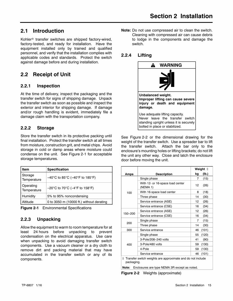
2.2.4 Lifting
Unbalanced weight.Improper lifting can cause severeinjury or death and equipmentdamage.
Use adequate lifting capacity.Never leave the transfer switchstanding upright unless it is securelybolted in place or stabilized.
WARNING
See Figure 2-2 or the dimensional drawing for theweight of the transfer switch. Use a spreader bar to liftthe transfer switch. Attach the bar only to theenclosure’s mounting holes or lifting brackets; do not liftthe unit any other way. Close and latch the enclosuredoor before moving the unit.
Amps Description
Weight ]
kg (lb.)
100
Single phase 7 (15)
With 12- or 16-space load center(NEMA 1)
12 (26)
With 16-space load center 8 (18)
Three phase 14 (30)
Service entrance (ASE) 12 (26)
Service entrance (CSE) 16 (34)
150--200Service entrance (ASE) 12 (26)
Service entrance (CSE) 16 (34)
200Single phase 7 (15)
Three phase 14 (30)
300 Service entrance 46 (101)
400
Single phase 55 (120)
3-Pole/208--240 volts 41 (90)
3-Pole/480 volts 59 (130)
4-Pole 59 (130)
Service entrance 46 (101)
] Transfer switch weights are approximate and do not includepackaging.
Note: Enclosures are type NEMA 3R except as noted.
Figure 2-2 Weights (approximate)
TP-6807 1/1616 Section 2 Installation
2.3 Installation
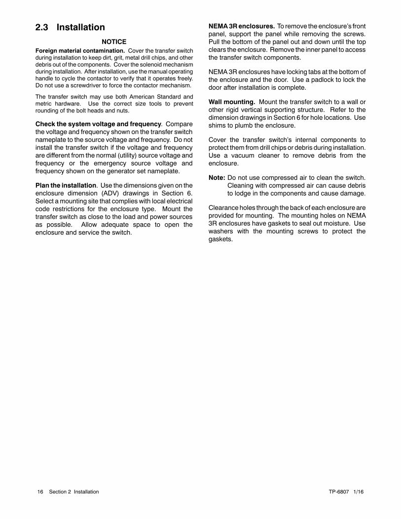
NOTICEForeign material contamination. Cover the transfer switchduring installation to keep dirt, grit, metal drill chips, and otherdebris out of the components. Cover the solenoidmechanismduring installation. After installation, use themanual operatinghandle to cycle the contactor to verify that it operates freely.Do not use a screwdriver to force the contactor mechanism.
The transfer switch may use both American Standard andmetric hardware. Use the correct size tools to preventrounding of the bolt heads and nuts.
Check the system voltage and frequency. Comparethe voltage and frequency shown on the transfer switchnameplate to the source voltage and frequency. Do notinstall the transfer switch if the voltage and frequencyare different from the normal (utility) source voltage andfrequency or the emergency source voltage andfrequency shown on the generator set nameplate.
Plan the installation. Use the dimensions given on theenclosure dimension (ADV) drawings in Section 6.Select amounting site that complies with local electricalcode restrictions for the enclosure type. Mount thetransfer switch as close to the load and power sourcesas possible. Allow adequate space to open theenclosure and service the switch.
NEMA3Renclosures. To remove the enclosure’s frontpanel, support the panel while removing the screws.Pull the bottom of the panel out and down until the topclears the enclosure. Remove the inner panel to accessthe transfer switch components.
NEMA3Renclosures have locking tabs at the bottomofthe enclosure and the door. Use a padlock to lock thedoor after installation is complete.
Wall mounting. Mount the transfer switch to a wall orother rigid vertical supporting structure. Refer to thedimension drawings in Section 6 for hole locations. Useshims to plumb the enclosure.
Cover the transfer switch’s internal components toprotect them fromdrill chips or debris during installation.Use a vacuum cleaner to remove debris from theenclosure.
Note: Do not use compressed air to clean the switch.Cleaning with compressed air can cause debristo lodge in the components and cause damage.
Clearanceholes through the backof eachenclosureareprovided for mounting. The mounting holes on NEMA3R enclosures have gaskets to seal out moisture. Usewashers with the mounting screws to protect thegaskets.
TP-6807 1/16 17Section 2 Installation
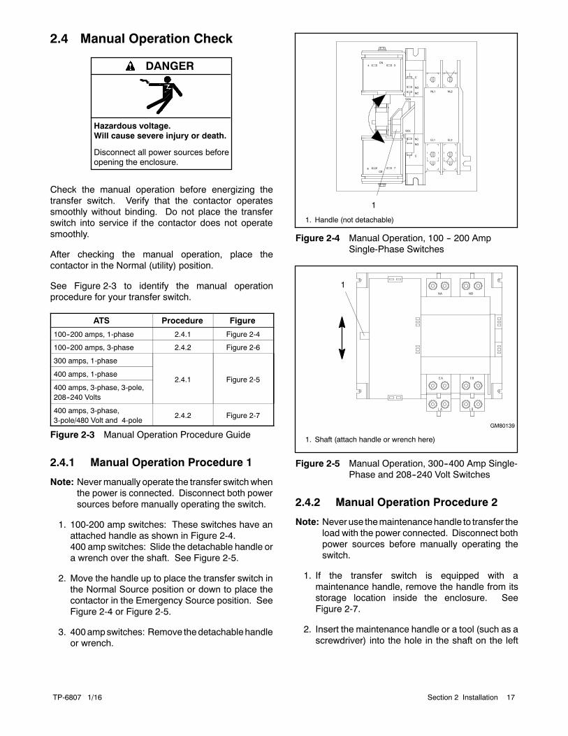
2.4 Manual Operation Check
Hazardous voltage.Will cause severe injury or death.
Disconnect all power sources beforeopening the enclosure.
DANGER
Check the manual operation before energizing thetransfer switch. Verify that the contactor operatessmoothly without binding. Do not place the transferswitch into service if the contactor does not operatesmoothly.
After checking the manual operation, place thecontactor in the Normal (utility) position.
See Figure 2-3 to identify the manual operationprocedure for your transfer switch.
ATS Procedure Figure
100--200 amps, 1-phase 2.4.1 Figure 2-4
100--200 amps, 3-phase 2.4.2 Figure 2-6
300 amps, 1-phase
2.4.1 Figure 2-5400 amps, 1-phase
400 amps, 3-phase, 3-pole,208--240 Volts
400 amps, 3-phase,3-pole/480 Volt and 4-pole
2.4.2 Figure 2-7
Figure 2-3 Manual Operation Procedure Guide
2.4.1 Manual Operation Procedure 1
Note: Nevermanually operate the transfer switchwhenthe power is connected. Disconnect both powersources before manually operating the switch.
1. 100-200 amp switches: These switches have anattached handle as shown in Figure 2-4.400 amp switches: Slide the detachable handle ora wrench over the shaft. See Figure 2-5.
2. Move the handle up to place the transfer switch inthe Normal Source position or down to place thecontactor in the Emergency Source position. SeeFigure 2-4 or Figure 2-5.
3. 400ampswitches: Remove thedetachablehandleor wrench.
4 3
78
CN
CE
NL1 NL2
EL2EL1
SCN
C
NO
NC
SCE
C
NC
NO
1
1. Handle (not detachable)
Figure 2-4 Manual Operation, 100 -- 200 AmpSingle-Phase Switches
1
GM80139
1. Shaft (attach handle or wrench here)
Figure 2-5 Manual Operation, 300--400 Amp Single-Phase and 208--240 Volt Switches
2.4.2 Manual Operation Procedure 2
Note: Never use themaintenancehandle to transfer theload with the power connected. Disconnect bothpower sources before manually operating theswitch.
1. If the transfer switch is equipped with amaintenance handle, remove the handle from itsstorage location inside the enclosure. SeeFigure 2-7.
2. Insert the maintenance handle or a tool (such as ascrewdriver) into the hole in the shaft on the left

TP-6807 1/1618 Section 2 Installation
side of the operator as shown in Figure 2-6 orFigure 2-7.
3. Move the maintenance handle (or tool) up or downasshown tomanually operate the transfer switch. Itshould operate smoothly without any binding. If itdoes not, check for shipping damage orconstruction debris.
4. Return the transfer switch to the Normal position.
5. Remove the maintenance handle and return it to thestorage location.
1. Insert handle or tool here for manual operation
GM78867
1
Figure 2-6 Manual Operation, 100--200 Amp3-Phase Switches
tp6225
1
2
1. Handle storage location2. Insert handle here for manual operation
Figure 2-7 Manual Operation, 400 Amp 3-PhaseSwitches
2.5 Electrical Wiring
Refer to the connection diagrams on the transfer switchenclosure door and the wiring diagrams in Section 6during installation.
All wiring must comply with applicable national, state,and local electrical codes. Use separate conduit for ACpower wiring and low-voltage DC, control, andcommunication system wiring.
Accidental starting.Can cause severe injury or death.
Disconnect the battery cables beforeworking on the generator set.Remove the negative (--) lead firstwhen disconnecting the battery.Reconnect the negative (--) lead lastwhen reconnecting the battery.
WARNING
Disabling the generator set. Accidental starting cancause severe injury or death. Before working on thegenerator set or equipment connected to the set, disable thegenerator set as follows: (1) Press the generator set off/resetbutton to shut down the generator set. (2) Disconnect thepower to the battery charger, if equipped. (3) Remove thebattery cables, negative (--) lead first. Reconnect the negative(--) lead last when reconnecting the battery. Follow theseprecautions to prevent the starting of the generator set by theremote start/stop switch.
Hazardous voltage.Will cause severe injury or death.
Disconnect all power sources beforeopening the enclosure.
DANGER
Making line or auxiliary connections. Hazardous voltagecan cause severe injury or death. To prevent electricalshock deenergize the normal power source beforemaking anyline or auxiliary connections.

TP-6807 1/16 19Section 2 Installation
Grounding electrical equipment. Hazardous voltage cancause severe injury or death. Electrocution is possiblewhenever electricity is present. Ensure you comply with allapplicable codes and standards. Electrically ground thegenerator set and related equipment and electrical circuits.Turn off the main circuit breakers of all power sources beforeservicing the equipment. Never contact electrical leads orappliances when standing in water or on wet ground becausethese conditions increase the risk of electrocution.
2.5.1 Load Center Circuit Breakers
The 100 amp Model RXT transfer switch is availablewith a built-in load center with room for up to 16single-pole circuit breakers. Up to 8 tandem breakerscan be used for a maximum of 24 circuits.
A 100 amp model with a 12-space load center is alsoavailable. The 12-space load center uses only singlebreakers. Do not install tandem breakers on the12-space load center.
The load centers useSquareD typeQOorQOT tandembreakers. In an essential load application, the breakerscan be moved from the main panel to the load center ifthe main distribution panel uses the same type ofbreakers. Otherwise, obtain and install new Square Dtype QO circuit breakers. The rating of the load centercircuit breaker must match the rating of the existingbreaker in the main panel for each circuit.
Verify that the total rating for all breakersused in the loadcenter does not exceed the rating of the transfer switch.
If circuit breakers are removed from the load panel,install cover plates over the vacant positions. Coverplates can be obtained from a local Square D supplier.
2.5.2 AC Power Connections
Determine the cable size. Refer to the ADV drawingsin Section 6 or the transfer switch specification sheet todetermine the cable size required for the transfer switch.Make sure the lugsprovided are suitable for usewith thecables being installed.
Conduit. Use separate conduit for AC power wiringand low-voltage DC, control, and communicationsystemwiring. Watertight conduit hubsmaybe requiredfor outdoor use.
Select the proper cable clamp or use other approvedmethods for securing the cable or conduit to theenclosure.
Source and load connections. Clean cables with awire brush to remove surface oxides before connectingthem to the terminals. Apply joint compound to theconnections of any aluminum conductors.
Refer to the connection diagrams on the transfer switchenclosure door and the wiring diagrams in Section 6.The connection points on the transfer switch contactorare labelled Normal, Emergency, and Load. Connectthe utility power toNormal. Connect the generator set toEmergency.
Single phase. For single-phase models, connect to Aand C.
Three phase. For three-phase models, be sure tofollow the phase markings (A, B, C, and N).
Note: Connect the sourceand loadphasesas indicatedby the markings and drawings to prevent shortcircuits and to prevent phase-sensitive devicesfrom malfunctioning or operating in reverse.
Serviceentrancemodels. Connect theutility source tothe lugs on the normal source disconnect circuitbreakers as shown in the service entrance switchwiringdiagram in Section 6.
Verify that all connections are consistent with drawingsbefore tightening the lugs. Tighten all cable lugconnections to the torque values shown on the label onthe switch. Carefully wipe off any excess jointcompound after tightening the terminal lugs.
On models with built-in load centers, the load lugs arefactory-wired to the load center. Connect the load leadsto the circuits in the load center and tighten theconnections. Check the labels on the breakers for thetightening torques.
2.5.3 Neutral Connection
Connect the neutral from the main panel to the neutrallug in the ATS enclosure.
Ground the system according to NEC and local codes.
2.5.4 Neutral Bonding Jumper, ServiceEntrance Models
The transfer switch is shipped with theneutral-to-ground jumper installed. For non-serviceentranceapplications, disconnect theneutral-to-groundbonding jumper. See the transfer switch dimensiondrawing.
2.5.5 Engine Start Function
Theengine start function is controlledby theRDC2/DC2controller on the generator set. There are no enginestart terminals on the Model RXT ATS.

TP-6807 1/1620 Section 2 Installation
2.6 Interface Module Connection
The interface module must be connected to a Kohlerrgenerator set equipped with the RDC2 or DC2controller. Connect P10 on the interface module to theA, B, PWR, and COM connections on the generatorset’s field-connection terminal block. See the generatorset Installation Manual for the location of the terminalblock. See Figure 2-8 for P10 connection identification.
Note: Engine start connections 3 and 4 on thegenerator set are not used with the Model RXTtransfer switch.
This document gives connection information for oneModel RXT transfer switch connected to a generator setequipped with an RDC2 or DC2 controller. If additionalaccessory modules such as a programmable interfacemodule (PIM) or a load control module (LCM) areconnected, refer to the generator set installationmanualfor connection instructions.
Accidental starting.Can cause severe injury or death.
Disconnect the battery cables beforeworking on the generator set.Remove the negative (--) lead firstwhen disconnecting the battery.Reconnect the negative (--) lead lastwhen reconnecting the battery.
WARNING
Disabling the generator set. Accidental starting cancause severe injury or death. Before working on thegenerator set or equipment connected to the set, disable thegenerator set as follows: (1) Press the generator set off/resetbutton to shut down the generator set. (2) Disconnect thepower to the battery charger, if equipped. (3) Remove thebattery cables, negative (--) lead first. Reconnect the negative(--) lead last when reconnecting the battery. Follow theseprecautions to prevent the starting of the generator set by theremote start/stop switch.
Hazardous voltage.Will cause severe injury or death.
Disconnect all power sources beforeopening the enclosure.
DANGER
Making line or auxiliary connections. Hazardous voltagecan cause severe injury or death. To prevent electricalshock deenergize the normal power source beforemaking anyline or auxiliary connections.
RBUS Connections A and B
See Figure 2-9 and Figure 2-10.
For the RBUS communication connections A and B tothe Model RXT transfer switch, optional PIM and/oroptional LCM or load shed kit, use 20 AWG shielded,twisted-pair communication cable. Belden #9402(two-pair) or Belden #8762 (single-pair) or equivalentcable is recommended.
For outdoor installations, including those with buriedcables and/or conduit, use outdoor-rated Belden#1075A or equivalent 20 AWG shielded, twisted-paircommunication cable.
PWR and COM Connections
For the PWR and COM connections, the cable size andmaximum cable length depends on the number ofmodules connected. See Figure 2-9.
D For short cable runs shown in the first two rows ofFigure 2-9, use one pair in the two-paircommunication cable for the A and B connections,and use the second pair for the PWR and COMconnections.
D For the longer cable runsshown in the last two rowsofFigure 2-9, use 12 or 14 AWG cable for PWR andCOM, and use the 20 AWG communication cablespecified above for the A and B connections only. Inthis case, single-pair communication cable such asBelden #8762 can be used for the A and Bconnections.
The maximum cable length depends on the number ofoptional modules connected. See Figure 2-9 for themaximumcable lengthswith1, 2, or 3modulesper cablerun.
Connection Designation Description
P10-1 A Communication Line
P10-2 B Communication Line
P10-3 PWR 12 VDC
P10-4 COM 12 VDC
Figure 2-8 Controller Interface Connections

TP-6807 1/16 21Section 2 Installation
Maximum cable length per run, meters (ft.)Indoor orOutdoor
Installation Cable Size for PWR and COM Connections
Number of Modules per Run
1 Module 2 Modules 3 Modules61 (200) 31 (100) 21 (67) Indoor 20 AWG Belden #9402 or equivalent, two-pair
61 (200) 31 (100) 21 (67) Outdoor 20 AWG Belden #1075A or equivalent, two-pair
152 (500) 152 (500) 122 (400) — 14 AWG *
152 (500) 152 (500) 152 (500) — 12 AWG *
* Use 12 or 14 AWG cable for PWR and COM connections only. For RBUS connections A and B, use shielded, twisted pair communicationcable specified in Section 2.6.
Figure 2-9 Cable Specifications for PWR and COM Connections
1. Communication cable Belden #9402 or equivalent 20 AWG shielded, twisted-pair cable.See Figure 2-9 for cable specifications.
Interface Board on the ModelRXT Transfer Switch
Note: Generator set terminal block connections 3 and 4 areNOT USED with the Model RXT ATS.
RXT
Leave one end of each cable shield disconnected.
If accessory modules are connected in series, connectthe cable shields as shown below and refer to thegenerator set installation manual.
Generator Set
COM
PWR
B
A
Connect one end of eachcable shield to GROUND atthe generator set.
RXT
COM
PWR
B
A
1
GND
Generator Set Terminal Block.See the generator set manuals for location.Check the decal on the generator set for terminalblock connections.
A
B
COM
PWR
3
4
Figure 2-10 Interface Module Connection to Generator Set Field-Connection Terminal Block

TP-6807 1/1622 Section 2 Installation
2.7 Combined Interface/LoadManagement Board
The combined interface/ load management board canbe usedwith single-phase generator sets equippedwiththeRDC2orDC2controller only. Follow the instructionsin this section to install the current transformer andconnect the loadmanagement relays. Thenconnect theinterface/ load management board to a Kohlerrgenerator set equipped with the RDC2 or DC2controller.
Up to four load relays and two HVAC relays can beconnected. The load management operation will cyclethrough all six connections regardless of the number ofloads connected. The load management timing isaffected by the generator’s capacity as described inSection 3.5.
Note: Only one load management option can be usedwith thegenerator. If a loadcontrolmodule (LCM)is connected, disable the load managementfunction on the combined interface/ loadmanagement board as described in Section 2.8and connect the LCM according to instructionsheet TT-1574, provided with the LCM.
2.7.1 Relay Modules
Up to four power relay modules (GM92001-KP1-QS)can be connected for management of non-essentialsecondary loads. Two (2) 120 VAC loads (shedsimultaneously) or a single 240 VAC load can be wiredto each relay. Customer-supplied relays must be eithernormally closed or double-pole double-trhow (DPDT)and maximum 50 amps. Note that the load must beconnected to the normally closed contacts of the relay.Kohlerr Power Relay Modules are recommended.
Circuit BoardRelays Rating
Pilot Relays andHVAC Relays
(qty. 2)
125VAC, 10 A (general purpose)120VAC, 125VA (pilot duty)
Figure 2-11 Combined Interface Board RelaySpecifications
Power Relay Specifications
Relay Rating 50 A @ 240 VAC
Relay Type DPST -- NC or DPDT
Coil Voltage 120 VAC
Figure 2-12 Customer-Supplied Power RelaySpecifications
Kohlerr power relay modules include one power relaymounted insideaNEMA type3Renclosure. Connect upto four (4) power relaymodules to the load shed kit. SeeFigure 2-13 for an illustration of a power relay module.
Before starting the installation, confirm that thegenerator set is equipped with an RDC2 or DC2controller. RDC2/DC2 controller firmware version 5.04or higher is required. Check the version number on thecontroller and update the firmware, if necessary.
An adequate electrical supply is required for operationof the customer-supplied relays connected to the loadshed kit. 120 VAC relays require a customer-suppliedvoltagesource. Check theelectrical requirementsof thecustomer-provided equipment prior to installation todetermine the wire size and circuit protection required.Verify that customer-provided equipment complies withapplicable local and national electrical codes.
Figure 2-13 Kohler Power Relay Module
2.7.2 HVAC Loads
There are two (2) relays available to control two (2)independent heating, ventilation, and air conditioning(HVAC) loads. The operation of the HVAC relaysincludes a five-minute start delay and different timing forload add compared to the power relays. SeeSection 3.5.1 for more details about the HVAC relayoperation.
2.7.3 Load Add/Shed Priority
Loads are prioritized from priority 1 to priority 6. SeeFigure 2-19 on page 25. Priority 1 is considered themost critical; it will add first and shed last. Priority 6 isconsidered the least critical; it will add last and shed first.

TP-6807 1/16 23Section 2 Installation
2.7.4 Current Transformers (CTs)
A current transformer is required for load management.A 400 amp current transformer is included with thecombined interface/ load management board. If theapplication requires cables that are too large for theinside diameter of the CT provided, or a 500 Amp CT isneeded for the 60RCL, order a current transformer orobtain a current transformer that meets thespecifications shown in Figure 2-14.
StandardCT
(included)
LargerDiameter CT*
(soldseparately)
500 Amp CT[(sold
separately)
Kit Number GM83929 GM17250-KP1-QS GM17250-KP2-QS
CT Service PartNumber GM83929 GM17250 GM60264
Primary Rating 400 Amps 400 Amps 500 Amps
SecondaryRating 3 VAC 3 VAC 3 VAC
BurdenResistor 16 Ohms 16 Ohms 16 Ohms
BurdenResistorLocation
Internal Internal Internal
Outer Diameter(O.D.)
63.5 mm(2.50 in.)
111.8 mm(4.40 in.)
171.5 mm(6.75 in.)
Inner Diameter(I.D.)
28.7 mm(1.13 in.)*
57.2 mm(2.25 in.)
108.0 mm(4.25 in.)
* Order GM17250--KP1--QS for applications that use larger cables.
[ Order GM17250--KP2--QS for 60RCL only.
Figure 2-14 Current Transformer (CT) Specifications
2.7.5 Connection Procedure
Accidental starting.Can cause severe injury or death.
Disconnect the battery cables beforeworking on the generator set.Remove the negative (--) lead firstwhen disconnecting the battery.Reconnect the negative (--) lead lastwhen reconnecting the battery.
WARNING
Disabling the generator set. Accidental starting cancause severe injury or death. Before working on thegenerator set or equipment connected to the set, disable thegenerator set as follows: (1) Press the generator set off/resetbutton to shut down the generator set. (2) Disconnect thepower to the battery charger, if equipped. (3) Remove thebattery cables, negative (--) lead first. Reconnect the negative(--) lead last when reconnecting the battery. Follow theseprecautions to prevent the starting of the generator set by theremote start/stop switch.
Hazardous voltage.Will cause severe injury or death.
Disconnect all power sources beforeopening the enclosure.
DANGER
Making line or auxiliary connections. Hazardous voltagecan cause severe injury or death. To prevent electricalshock deenergize the normal power source beforemaking anyline or auxiliary connections.
1. Press the OFF button on the generator setcontroller.
2. Disconnect the utility power to the generator set.
3. Disconnect the generator set engine startingbattery(ies), negative (--) lead first.
4. Disconnect power to the transfer switch.
5. Remove the ATS enclosure cover.
6. Install the current transformer (CT) on theemergency source lines. Installation inside thetransfer switch enclosure is recommended.
Note: Be sure to route the leads through thecurrent transformer from opposite sides asshown in Figure 2-15. The leadsmust crossin opposite directions as they pass throughthe transformer.
Note: See Section 2.7.4 for CT specifications.
Emergency sourceleads must crossthrough CT in oppositedirections as shown.
FROM GENERATOR
EMERGENCY LUGS ON ATS
GM88804
To TB1 on LoadShed Circuit Board
CTside view
Figure 2-15 Current Transformer (CT) Wiring

TP-6807 1/1624 Section 2 Installation
7. RBUS connections: Connect the controllerinterface connection to A, B, PWR, and COM onterminal block P10 on the interface/ loadmanagement board See Figure 2-16 andFigure 2-18. The RBUS connections to thegenerator set controller are the same for thestandard interface board and the combined board.See Section 2.6 for interface connectioninstructions.
Note: Use separate conduit for the low-voltagecontroller communication leadsand the loadconnection wiring.
Note: Refer to the wiring diagrams in Section 6.
8. Connect the CT leads to connector TB1 on theinterface/ load management circuit board. Extendthe leads, if necessary, using customer-suppliedwiring. See Figure 2-18 and/or the wiring diagramin Section 6 for the connector location.
9. Note the load priorities shown in Figure 2-19.Priority 1 is considered themost critical andwill addfirst and shed last. Priority 6 is considered the leastcritical and will add last and shed first.
Connect the customer-provided load relays toterminal block TB2 for Loads A, B, C, and D. SeeFigure 2-17 for the connections. SeeSection 2.7.1for the recommended relay specifications.
Note: The combination of four load relay outputscannot exceed 10 amps total current draw.
10. Connect 120 VAC power to TB2 connections AC1and N. See Figure 2-17. Connect 120 VAC linevoltage to terminal AC1. Connect the neutral to N.The power to this circuit must be backed up by thegenerator set andnot bepart of a sheddable circuit.
11. Verify that the jumper is installed acrossP11--2 andP11--3 on the combined interface board. SeeFigure 2-18.
1
ADV--8691
1. Combined interface / load management board inside theenclosure
SIDE VIEW
Figure 2-16 Typical Interface Board Location
GM95547
Figure 2-17 Power Relay Circuit on the CombinedInterface/Load Management Board
TP-6807 1/16 25Section 2 Installation
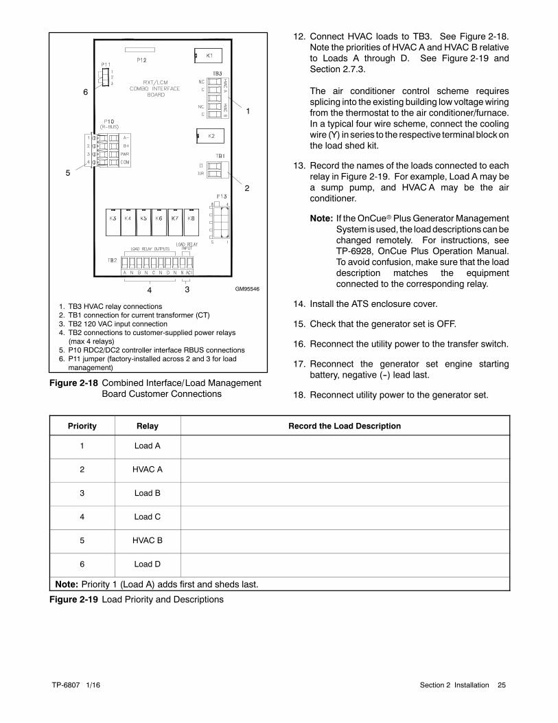
GM95546
1. TB3 HVAC relay connections2. TB1 connection for current transformer (CT)3. TB2 120 VAC input connection4. TB2 connections to customer-supplied power relays
(max 4 relays)5. P10 RDC2/DC2 controller interface RBUS connections6. P11 jumper (factory-installed across 2 and 3 for load
management)
4
1
5
2
3
6
Figure 2-18 Combined Interface/Load ManagementBoard Customer Connections
12. Connect HVAC loads to TB3. See Figure 2-18.Note the priorities of HVAC A and HVAC B relativeto Loads A through D. See Figure 2-19 andSection 2.7.3.
The air conditioner control scheme requiressplicing into the existing building low voltagewiringfrom the thermostat to the air conditioner/furnace.In a typical four wire scheme, connect the coolingwire (Y) in series to the respective terminal blockonthe load shed kit.
13. Record the names of the loads connected to eachrelay in Figure 2-19. For example, Load A may bea sump pump, and HVAC A may be the airconditioner.
Note: If the OnCuerPlus Generator ManagementSystem isused, the loaddescriptions canbechanged remotely. For instructions, seeTP-6928, OnCue Plus Operation Manual.To avoid confusion, make sure that the loaddescription matches the equipmentconnected to the corresponding relay.
14. Install the ATS enclosure cover.
15. Check that the generator set is OFF.
16. Reconnect the utility power to the transfer switch.
17. Reconnect the generator set engine startingbattery, negative (--) lead last.
18. Reconnect utility power to the generator set.
Priority Relay Record the Load Description
1 Load A
2 HVAC A
3 Load B
4 Load C
5 HVAC B
6 Load D
Note: Priority 1 (Load A) adds first and sheds last.
Figure 2-19 Load Priority and Descriptions

TP-6807 1/1626 Section 2 Installation
2.8 Load Control Module (LCM)
Note: Only one load management option can be usedwith the generator. If the LCM is connected to anRXT equipped with the combined interface/ loadmanagement board, disable the loadmanagement function on the combined board asdescribed in Section 2.8.2, below.
2.8.1 LCM with Standard InterfaceBoard
If the Load Control Module (LCM) is used with an RXTtransfer switch equipped with the standard interfaceboard, follow the instructions in TT-1574, provided withthe LCM, to connect the load control module and thecurrent transformer.
2.8.2 LCM with Combined InterfaceBoard
If the LCM is used with an RXT that is equipped with thecombined interface/ load management board, disablethe loadmanagement function on the interface board asdescribed in the procedure below. Connect the LCM asdescribed in TT-1574. Be sure to connect the currenttransformer to the LCM (not to the combinedinterface/ load management board on the RXT).
Note: The load status LEDs on the status indicator forthe combined interface/ load management boardwill not show the load control status of the LCM.
Accidental starting.Can cause severe injury or death.
Disconnect the battery cables beforeworking on the generator set.Remove the negative (--) lead firstwhen disconnecting the battery.Reconnect the negative (--) lead lastwhen reconnecting the battery.
WARNING
Disabling the generator set. Accidental starting cancause severe injury or death. Before working on thegenerator set or equipment connected to the set, disable thegenerator set as follows: (1) Press the generator set off/resetbutton to shut down the generator set. (2) Disconnect thepower to the battery charger, if equipped. (3) Remove thebattery cables, negative (--) lead first. Reconnect the negative(--) lead last when reconnecting the battery. Follow theseprecautions to prevent the starting of the generator set by theremote start/stop switch.
Hazardous voltage.Will cause severe injury or death.
Disconnect all power sources beforeopening the enclosure.
DANGER
Making line or auxiliary connections. Hazardous voltagecan cause severe injury or death. To prevent electricalshock deenergize the normal power source beforemaking anyline or auxiliary connections.
Procedure to connect an LCM if the combinedboard is used on the RXT
1. Press the OFF button on the generator setcontroller.
2. Disconnect the utility power to the generator set.
3. Disconnect the generator set engine startingbattery(ies), negative (--) lead first.
4. Disconnect power to the transfer switch.
5. Remove the ATS enclosure cover.
6. Find the combined interface/ load managementboard, which is typically mounted on the upper leftside of the enclosure. See Figure 2-16, ifnecessary.
7. See Figure 2-20. Move the P11 jumper fromterminals 2 and 3 to terminals 1 and 2 to disable theloadmanagement functionon thecombinedboard.

TP-6807 1/16 27Section 2 Installation
8. Connect RBUS communication cable to thecombined interface board: Connect the generatorcontroller’s interface connection to A, B, PWR, andCOM on terminal block P10 on the interface/ loadmanagement board. See Figure 2-20. SeeSection 2.6 for detailed RBUS connectioninstructions.
9. Follow the instructions in TT-1574, provided withthe LCM, to connect the load control module.
a. Connect the LCM RBUS connections to eitherthe combined interface board or to thegenerator’s RDC2 or DC2 controller.
b. Connect the current transformer (CT) to theLCM. Do not connect the CT to the combinedinterface board in the RXT enclosure.
c. Connect power relays,HVACconnections, and120 VAC power to the LCM as described inTT-1574.
10. Install the ATS enclosure cover.
11. Check that the generator set is OFF.
12. Reconnect the utility power to the transfer switch.
13. Reconnect the generator set engine startingbattery, negative (--) lead last.
14. Reconnect utility power to the generator set.
1
1. P11: Install jumper across pins 1 and 2 to disable loadmanagement
2. Connect RBUS communication cable to P10 on thecombined board.
Note: DONOTconnect power relays,HVACrelays, orcurrent transformer to the combined board.Connect to the LCM as described in the LCMinstruction sheet.
GM90773
2
DO NOTCONNECT
TB2: DO NOT CONNECT
Figure 2-20 Combined Interface/ Load ManagementBoard Connections with LCM

TP-6807 1/1628 Section 2 Installation
2.9 Optional Load ControlConnection
Connector P11 on the standard interface moduleprovides a connection point for optional load controlcircuits. The load control contact provides a delayedcontact closure to allow startup of selected loads 5minutes after transfer to the emergency power source(generator set). Use this contact to delay startup ofequipment with large motor-starting loads such as airconditioners.
See Figure 2-21 for the location of load controlconnector P11. See Figure 2-22 for contact ratings,connection, and wire size information.
Note: For load add and load shed operation based ongenerator capacity, use the load shed kit or thecombined interface/ load management board.See Sections 1.4.2, 2.7, and 3.4 for moreinformation about load management.
1. Load control connection P11
GM806631
Figure 2-21 Load Control Connection, StandardInterface Board
2.10 Accessory ModuleConnections
For connection of the optional programmable interfacemodule (PIM), refer to the instructions provided with themodule and to the generator set installation manual.
2.11 Test and Exercise
Refer to the generator set Operation Manual forinstructions to test the power system operation and toset theRDC2orDC2 controller for weekly exercise runsto keep the power system in good operating condition.
2.12 Warranty Registration
Startup Notification Form. The Startup NotificationForm covers all equipment in the standby system.Complete the Startup Notification Form and register theequipment in the Kohler online warranty system within60 days of the initial startup date.
Terminal Block Connection Designation Description Contact Rating Wire Size
P11P11-1 LC1
Load Control Output10 A @ 250 VAC1 A @ 30 VDC #12--18 AWG
P11-2 LC2
Figure 2-22 Load Control Contact P11 Connections

TP-6807 1/16 29Section 3 Operation
Section 3 Operation
3.1 Model RXT Transfer SwitchOperation
The Model RXT transfer switch must be connected to agenerator set equipped with the RDC2 or DC2controller. The RDC2/DC2 generator set/transferswitch controller manages automatic transfer switch(ATS) functions when connected to a Kohlerr ModelRXT transfer switch through the ATS interface board.The controller receives voltage sensing data from theModel RXT ATS and operates the generator set andtransfer switch to provide standby power when utilitypower is lost.
See the generator set operation manual for:
D ATS status screens and configuration menus.
D Information about loaded exercise.
3.2 Source Availability
The Model RXT transfer switch supplies voltagesensing data to the RDC2 or DC2 controller through theATS interface board. If the source voltage falls belowthe undervoltage dropout setting, the source isconsidered to have failed. See Figure 3-1.
Voltage Sensing Parameter Setting
Accuracy ±5%Undervoltage Dropout 90% of Pickup
Undervoltage Pickup 90% of Nominal
Figure 3-1 Voltage Sensing Parameters
3.3 ATS Control Sequence ofOperation
See Figure 3-10 for time delay settings.
Preferred Source Fails:
1. The load control contact opens.
2. The engine start time delay times out.
3. The generator set is signaled to start.
4. The generator starts and the emergency sourcebecomes available.
5. The normal-to-emergency time delay times out.
6. The transfer switch transfers to the emergencysource.
7. The load control contact time delay times out.
8. The load control contact closes.
Normal Source Returns:
1. The emergency-to-normal time delay times out.
2. The contactor transfers to the normal source.
3. The engine cooldown time delay times out.
4. The generator is signaled to stop.
3.4 Load Management Operation
The combined interface/ load management boardprovides load add and shed based on generatorcapacity as described in this section.
Many appliances do not run continuously. Airconditioners and furnaces, refrigerators, sump pumps,and other appliances cycle on and off as needed. Withload management, less critical appliances can bepowered by the generator set when the more importantappliancesare not running, allowing the useof a smallergenerator set than would be needed to run all of thebuilding’s electrical equipment at the same time.
TheRDC2/DC2generator controller receives input fromcurrent transformer (provided with the combinedinterface/ load management board for installation in theATS) anddetermineswhether to addor shed loads. Thecombined interface/load management board receivescommands from the generator controller and energizesor de-energizes the appropriate load relays.
The load management function is activated by the ATStransferring from the utility (normal) source to thegenerator. When activated, the load managementboard sheds all connected loads. After transfer to thegenerator set, loads are added according to theirpriority.
If the ATS fails to transfer from the utility source to thegenerator, the load management board will re-add allloads. When the ATS transfers to utility, the loadmanagement board adds all loads that have beenpreviously shed.

TP-6807 1/1630 Section 3 Operation
For more information about the load add and load shedtiming, see Section 3.5, Load Management Theory ofOperation.
3.4.1 Power Loads
Up to four customer-supplied power relays can beconnected for management of non-essential secondaryloads. If two-pole relays are used, two (2) 120 VACloads (shed simultaneously) or a single 240 VAC loadcan be wired to each relay. See Section 2.7.1 for morepower relay information.
3.4.2 HVAC Loads
There are two (2) relays available to control two (2)independent heating, ventilation, and air conditioning(HVAC) loads.
A5-minute timedelaypreventsHVAC loads fromaddingtoo quickly. Air conditioning compressors may bedamaged if they start too soon after being stopped dueto the necessity of starting the compressor against alarge residual pressure. Five minutes is a typicallyaccepted time required for an AC compressor to bleedoff to a pressure level that the motor can successfullystart against.
3.4.3 Load Add/Shed Priority
Loads are prioritized from priority 1 to priority 6. SeeFigure 2-19 on page 25. Priority 1 is considered themost critical; it will add first and shed last. Priority 6 isconsidered the least critical; it will add last and shed first.
3.4.4 Status Indicator and Test Button
The optional status indicator panel for the combinedinterface/ load management board includes the sourceavailable and source connection LEDs and load statusLEDs. The panel also includes a Test button that cyclesthe load management relays. See Figure 3-2.
1
GM90763
1. Utility power available2. Utility source supplying load3. Generator source supplying load4. Generator power available5. Load add/shed relay status indicators (see Figure 3-3)6. Load shed test button (cycles relays)
2
3
4
5
6
Figure 3-2 Optional Status Indicator Panel forCombined Board

TP-6807 1/16 31Section 3 Operation
LED State/Color Indicates
UtilityAvailable
On Utility power is available
Off Utility power is not available
UtilityConnected
OnUtility power is connected (ATS
in normal position)
Off Utility power is not connected
GeneratorAvailable
OnGenerator set is running and
producing power
OffGenerator set power is not
available
GeneratorConnected
OnGenerator is connected to the
load (ATS in Emergencyposition)
Off Generator not connected
Loads Athrough D
Red Load disconnected (shed)
Green Load connected (added)
Flashing red Disconnected (test)
HVAC LoadsA, B
Red Load disconnected (shed)
Green Load connected (added)
Flashing red Disconnected (test)
Figure 3-3 LED Operation
LEDsprovidevisual indicationof the statusof each load.See Figure 3-2 and Figure 3-3.
Use the TEST button to exercise the load shed relays insequence according to the assigned priorities. Run thegenerator set in RUNmode, not AUTO, during this test.The generator set must be running, but the ATS mustNOT transfer to the generator set for this test.
Test Procedure
1. Press RUN on the RDC2 or DC2 generator setcontroller to start the generator set.
2. Press the TEST button on the indicator panel toexercise the first relay.
3. Press TEST again for the next relay, and repeat tocycle through all of the relays in order.
The test mode ends automatically after 15 minutes. Toend the test manually, hold the TEST button for5 seconds or press OFF or AUTO on the RDC2 or DC2generator set controller.
3.5 Load Management Theory ofOperation
3.5.1 Load Add
The load management board adds and sheds loadsbased on the available capacity of the generator set.When thegenerator hasampleavailable capacity, loadsare added quickly. When the available capacity is low,
loads are added more slowly to give the generator timeto recover and to allow ample time to ensure that anyswitching loads will come on before adding more loadthan the generator can handle.
The load add time ranges from 15 to 120 secondsdepending on the loading of the generator set.Figure 3-4 showsanexampleof the loadadd timing for a20 kW generator set with the maximum capacity set tothe default setting of 70%. Figure 3-5 shows the HVACload add timing for a 20 kW generator set.
AvailableCapacity
(%) Load (%)
Load (kW) fora 20 kWGenerator
Time(Seconds)
70% 0% 0 15
50% 20% 4 23
37% 33% 6.6 34
30% 40% 8 40
20% 50% 10 48
5% 65% 13 60
<5% >65% >13 kW Never Add
Figure 3-4 Example: Power Relay Load Add Timingfor a 20 kW Generator
AvailableCapacity
(%) Load (%)
Load (kW) fora 20 kWGenerator
Time *(Seconds)
70% 0% 0 30
50% 20% 4 66
37% 33% 6.6 91
30% 40% 8 102
20% 50% 10 120
<20% >50% >10 kW Never Add
* After the 5-minute HVAC delay
Figure 3-5 Example: HVAC Load Add Timing for a20 kW Generator
Capacity
The Generator Maximum Percent Capacity settingdictates the maximum level that the load managementboard will automatically place on the generator. Thissetting is adjustable using a laptop computer connectedto the RDC2 or DC2 controller and Kohlerr SiteTechtsoftware. See Section 3.5.6.
The maximum load is calculated by multiplying theGenerator Maximum Percent Capacity by the GensetPower Rating, which is a setting in the RDC2/DC2controller. The Genset Power Rating, in kW, isfactory-set to the natural gas rating. If the 14RESA or20RESA has been converted to LP fuel, use SiteTech toverify that the fuel type has been changed on thecontroller and theGensetPowerRating is correct. Referto the generator set specification sheet for the newrating, and change the fuel type under the Genset

TP-6807 1/1632 Section 3 Operation
System Configuration in SiteTecht. See Figure 3-6and TP-6701, SiteTech Software Operation Manual.
The load management function will operate if the ratingsetting is not changed, but loads will be shed at a kWlevel based on the factory default rating, rather than therating of the reconfigured generator set.
1
1. Genset Power Rating setting2. Genset Fuel Type setting
2
Figure 3-6 Genset Power Rating in SiteTech
3.5.2 Load Shed
Less important (larger priority number) loads are shedwhen the generator is unable to support them. Thispermits more important loads to continue to receivepower from the generator. The less important loads arere-added after the generator loading has gone downenough to support them again. The load managementboard sheds less important loads before the powerquality of the generator suffers from the overload.
Loads are shed in two ways – Overload and UnderFrequency.
3.5.3 Overload Shed
Loads are shed on a time scale which is based on thetotal generator overload. The loads will shed slowlywhen the generator is not heavily overloaded. Loadsare shed much more quickly when the overload ishigher. The timing variation allows consistent overloadsto be removed, instantaneous excessive overloads tobe very quickly removed and normal overloads (such asmotor inrush) to remain online until the transientoverload condition is removed.
Figure 3-7 shows the overload shed timing for a 20 kWgenerator set with the generator overloaded percent setto the default setting of 85%. If the overload conditionpersists, the load shed timing can be affected by loadshed acceleration. See Section 3.5.5.
The Generator Overload Percent setting is themaximum load that the load management board willacceptwithout shedding. Thesetting isadjustableusinga laptop computer connected to the RDC2 or DC2controller and Kohler SiteTech software. See Section3.5.6. Set theGenerator Overload Percent at least 10%higher than the Generator Maximum Percent Capacity.
GeneratorOverload
(%)Load (%)
Load (kW) fora 20 kWGenerator
Time(seconds)
0% <85% <17 kW Never Shed
0% 85% 17 40
10% 95% 19 28
13% 98% 19.6 24
15% 100% 20 22
20% 105% 21 17
>35% >120% >24 kW 0.5
Figure 3-7 Overload Shed Timing for a 20 kWGenerator
3.5.4 Under Frequency Shed
Loads are shed on a time scale which is based on thegenerator frequency droop. The loads will shed quicklywhen the frequency droop is high (output frequency islower), and more slowly when the generator is runningclose to rated frequency. The timing variation allowslarge overloads to be shed very quickly, while allowingthe generator to ride through normal transients (such asstarting an AC compressor).

TP-6807 1/16 33Section 3 Operation
Figure 3-8 shows the under frequency shed timing for a60 Hz generator set. If the underfrequency conditionpersists, the load shed timing can be affected by loadshed acceleration. See Section 3.5.5.
Frequency (Hz)FrequencyDroop (Hz) Time (seconds)
>59 Hz <1 Hz Never Shed
58.5 1.5 5.4
57 3 4.3
56 4 3.4
54 6 1.8
<52.5 Hz >7.5 Hz 0.3
Figure 3-8 Under Frequency Shed Timing for a60Hz Generator
3.5.5 Load Shed Acceleration
Load shed acceleration is used to shed loads morequickly if an overload or underfrequency conditionpersists. If an overload condition is not cleared byshedding a load, each subsequent load will shed morequickly. The acceleration is more pronounced for anunderfrequency shed.
3.5.6 Changing Settings
The Generator Maximum Percent Capacity andGenerator Overloaded Percent settings can bechanged using a laptop computer connected to theRDC2 or DC2 controller and Kohlerr SiteTechtsoftware. The load control settings are found in theGenset System Configuration group. See Figure 3-9and TP-6701, SiteTech Software Operation Manual.
Set theGeneratorOverloadPercent at least 10%higherthan the Generator Maximum Percent Capacity.
1tt1574
1. Load shed settings
Figure 3-9 SiteTech Screen
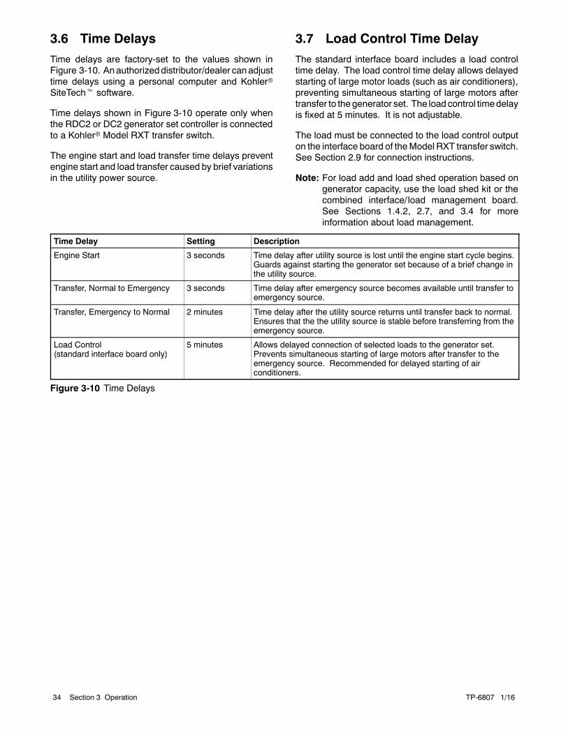
TP-6807 1/1634 Section 3 Operation
3.6 Time Delays
Time delays are factory-set to the values shown inFigure 3-10. Anauthorizeddistributor/dealer canadjusttime delays using a personal computer and KohlerrSiteTecht software.
Time delays shown in Figure 3-10 operate only whenthe RDC2 or DC2 generator set controller is connectedto a Kohlerr Model RXT transfer switch.
The engine start and load transfer time delays preventengine start and load transfer caused by brief variationsin the utility power source.
3.7 Load Control Time Delay
The standard interface board includes a load controltime delay. The load control time delay allows delayedstarting of large motor loads (such as air conditioners),preventing simultaneous starting of large motors aftertransfer to thegenerator set. The loadcontrol timedelayis fixed at 5 minutes. It is not adjustable.
The load must be connected to the load control outputon the interface board of theModel RXT transfer switch.See Section 2.9 for connection instructions.
Note: For load add and load shed operation based ongenerator capacity, use the load shed kit or thecombined interface/ load management board.See Sections 1.4.2, 2.7, and 3.4 for moreinformation about load management.
Time Delay Setting Description
Engine Start 3 seconds Time delay after utility source is lost until the engine start cycle begins.Guards against starting the generator set because of a brief change inthe utility source.
Transfer, Normal to Emergency 3 seconds Time delay after emergency source becomes available until transfer toemergency source.
Transfer, Emergency to Normal 2 minutes Time delay after the utility source returns until transfer back to normal.Ensures that the the utility source is stable before transferring from theemergency source.
Load Control(standard interface board only)
5 minutes Allows delayed connection of selected loads to the generator set.Prevents simultaneous starting of large motors after transfer to theemergency source. Recommended for delayed starting of airconditioners.
Figure 3-10 Time Delays

TP-6807 1/16 35Section 4 Service Disconnect, SE Model
Section 4 Service Disconnect, SE Model
Note: This section applies only to service entrancemodel transfer switches, which are identifiedwiththe lettersSEat theendof themodel designation.
Hazardous voltage.Will cause severe injury or death.
This equipment must be installed andserviced by qualified electricalpersonnel.
DANGER
Accidental starting.Can cause severe injury or death.
Disconnect the battery cables beforeworking on the generator set.Remove the negative (--) lead firstwhen disconnecting the battery.Reconnect the negative (--) lead lastwhen reconnecting the battery.
WARNING
Disabling the generator set. Accidental starting cancause severe injury or death. Before working on thegenerator set or equipment connected to the set, disable thegenerator set as follows: (1) Press the generator set off/resetbutton to shut down the generator set. (2) Disconnect thepower to the battery charger, if equipped. (3) Remove thebattery cables, negative (--) lead first. Reconnect the negative(--) lead last when reconnecting the battery. Follow theseprecautions to prevent the starting of the generator set by theremote start/stop switch.
4.1 Service Disconnect Procedure
Use the following procedure to disconnect the utilitysource on service entrance model transfer switches.
Note: Power is still present on the input side of the utilitysource circuit breaker after this procedure.
1. Prevent the emergency generator set fromstarting:
a. Press the OFF button on the generator setcontroller.
b. Disconnect power to the generator set batterycharger.
c. Disconnect the generator set engine startingbattery, negative (--) lead first.
2. On the transfer switch, remove the outer enclosuredoor only.
3. Move the utility source circuit breaker to the OFFposition.
Note: Power is still present on the input side of theutility source circuit breaker. Do not removethe protective barrier around the utilitysource connection lugs.
4. To lock out the transfer switch, replace the outerdoor and attach a padlock to the hasp.
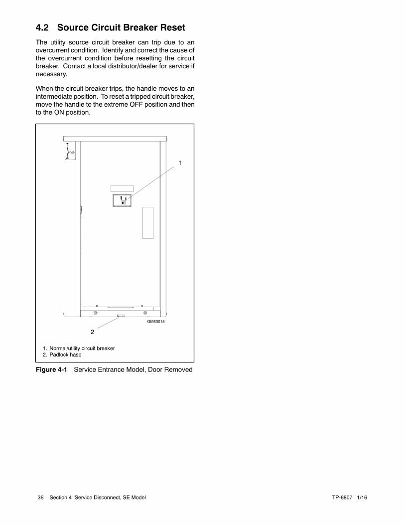
TP-6807 1/1636 Section 4 Service Disconnect, SE Model
4.2 Source Circuit Breaker Reset
The utility source circuit breaker can trip due to anovercurrent condition. Identify and correct the cause ofthe overcurrent condition before resetting the circuitbreaker. Contact a local distributor/dealer for service ifnecessary.
When the circuit breaker trips, the handle moves to anintermediate position. To reset a tripped circuit breaker,move the handle to the extreme OFF position and thento the ON position.
1
GM80015
1. Normal/utility circuit breaker2. Padlock hasp
2
Figure 4-1 Service Entrance Model, Door Removed

TP-6807 1/16 37Section 5 Scheduled Maintenance
Section 5 Scheduled Maintenance
5.1 Introduction
Regular preventive maintenance ensures safe andreliable operation and extends the life of the transferswitch. Preventive maintenance includes periodictesting, cleaning, inspection, and replacement of wornor missing components. Section 5.4 contains a serviceschedule for recommended maintenance tasks.
A local authorized distributor/dealer can providecomplete preventive maintenance and service to keepthe transfer switch in top condition. Unless otherwisespecified, havemaintenanceor serviceperformedbyanauthorized distributor/dealer in accordance with allapplicable codes and standards. See the ServiceAssistance section in this manual for how to locate alocal distributor/dealer.
Keep records of all maintenance or service.
Replace all barriers and close and lock the enclosuredooraftermaintenanceor serviceandbefore reapplyingpower.
Accidental starting.Can cause severe injury or death.
Disconnect the battery cables beforeworking on the generator set.Remove the negative (--) lead firstwhen disconnecting the battery.Reconnect the negative (--) lead lastwhen reconnecting the battery.
WARNING
Disabling the generator set. Accidental starting cancause severe injury or death. Before working on thegenerator set or equipment connected to the set, disable thegenerator set as follows: (1) Press the generator set off/resetbutton to shut down the generator set. (2) Disconnect thepower to the battery charger, if equipped. (3) Remove thebattery cables, negative (--) lead first. Reconnect the negative(--) lead last when reconnecting the battery. Follow theseprecautions to prevent the starting of the generator set by theremote start/stop switch.
Hazardous voltage.Will cause severe injury or death.
Disconnect all power sources beforeopening the enclosure.
DANGER
Hazardous voltage.Will cause severe injury or death.
Only authorized personnel shouldopen the enclosure.
DANGER
Grounding the transfer switch. Hazardous voltage cancause severe injury or death. Electrocution is possiblewhenever electricity is present. Open main circuit breakers ofall power sources before servicing equipment. Configure theinstallation to electrically ground the transfer switch andrelated equipment and electrical circuits to comply withapplicable codes and standards. Never contact electricalleads or appliances when standing in water or on wet ground,as the chance of electrocution increases under suchconditions.
Servicing the transfer switch. Hazardous voltage cancause severe injury or death. Deenergize all power sourcesbefore servicing. Turn off the main circuit breakers of alltransfer switch power sources and disable all generator setsas follows: (1) Press the generator set off/reset button to shutdown the generator set. (2) Disconnect power to all batterychargers. (3) Disconnect all battery cables, negative (--) leadsfirst. Reconnect negative (--) leads last when reconnecting thebattery cables after servicing. Follow these precautions toprevent the starting of generator sets by an automatic transferswitch, remote start/stop switch, or engine start commandfrom a remote computer. Before servicing any componentsinside the enclosure: (1) Remove all jewelry. (2) Stand on adry, approved electrically insulatedmat. (3) Test circuits with avoltmeter to verify that they are deenergized.

TP-6807 1/1638 Section 5 Scheduled Maintenance
Short circuits. Hazardous voltage/current can causesevere injury or death. Short circuits can cause bodily injuryand/or equipment damage. Do not contact electricalconnections with tools or jewelry while making adjustments orrepairs. Remove all jewelry before servicing the equipment.
NOTICEElectrostatic discharge damage. Electrostatic discharge(ESD) damages electronic circuit boards. Preventelectrostatic discharge damage by wearing an approvedgrounding wrist strap when handling electronic circuit boardsor integrated circuits. An approved grounding wrist strapprovides a high resistance (about 1 megohm), not a directshort, to ground.
The transfer switch may use both American Standard andmetric hardware. Use the correct size tools to preventrounding of the bolt heads and nuts.
Screws and nuts are available in different hardnessratings. To indicate hardness, American Standardhardware uses a series of markings and metrichardware uses a numeric system. Check the markingson the bolt heads and nuts for identification.
5.2 Testing
5.2.1 Weekly Generator Set ExerciseUse the exerciser or a manual test to start and run thegenerator set under load once a week to maximize thereliability of the emergency power system.
5.2.2 Monthly Automatic ControlSystem Test
Test the transfer switch’s automatic control systemmonthly. Refer to the RDC2/DC2 controller operationmanual for the test procedure.
D Verify that the expected sequence of operationsoccurs as the switch transfers the load to theemergency source when a preferred source failureoccurs or is simulated.
D Watch and listen for signs of excessive noise orvibration during operation.
D After the switch transfers the load to the standbysource, end the test and verify that the expectedsequence of operations occurs as the transfer switchretransfers to the preferred source.
5.3 Inspection and Service
Contact an authorized distributor/dealer to inspect andservice the transfer switch annually and also when anywear, damage, deterioration, or malfunction of thetransfer switch or its components is evident orsuspected.
5.3.1 General Inspection
External Inspection. Keep the transfer switch cleanand in good condition by performing a weekly generalexternal inspection of the transfer switch. Check for anycondition of vibration, leakage, excessive temperature,contamination, or deterioration. Remove accumulationsof dirt, dust, and other contaminants from the transferswitch’s external components or enclosure with avacuum cleaner or by wiping with a dry cloth or brush.
Note: Do not use compressed air to clean the transferswitch because it can cause debris to lodge in thecomponents and damage the switch.
Tighten loose external hardware. Replace worn, missing,or broken external components with manufacturer-recommended replacement parts. Contact anauthorized distributor/dealer for specific partinformation and ordering.
Internal Inspection. Disconnect all power sources,open the transfer switch enclosure door, and inspectinternal components monthly or when any conditionnoticed during anexternal inspectionmayhaveaffectedinternal components.
Contact an authorized distributor/dealer to inspect andservice the transfer switch if any of the followingconditions are found inside the transfer switch.
D Accumulations of dirt, dust, moisture, or othercontaminants.
D Signs of corrosion.
D Worn, missing, or broken components.
D Loose hardware.
D Wire or cable insulation deterioration, cuts, orabrasion.
D Signs of overheating or loose connections:discoloration of metal, melted plastic, or a burningodor.
D Other evidence of wear, damage, deterioration, ormalfunction of the transfer switch or its components.
If the application does not allow a power interruption forthe time required for the internal inspection, have anauthorized distributor/dealer perform the internalinspection.
5.3.2 Other Inspections and ServiceHave an authorized distributor/dealer performscheduled maintenance, service, and other

TP-6807 1/16 39Section 5 Scheduled Maintenance
maintenance that ensures the safe and reliableoperation of the transfer switch. See Section 5.4,Service Schedule, for the recommended maintenanceitems and service intervals.
Have an authorized distributor/dealer repair or replacedamaged or worn internal components withmanufacturer-recommended replacement parts.
5.4 Service Schedule
Follow the service schedule in Figure 5-1 for therecommended service intervals. Have all serviceperformedbyanauthorized distributor/dealer except foractivities designated by an X, which may be performedby the switch operator.
System Component or ProcedureSee
SectionVisuallyInspect Check
Adjust,Repair,Replace Clean Test Frequency
Electrical System
Check for signs of overheating or loose connections:discoloration of metal, melted plastic, or a burning odor 5.3.1 X X Y
Check the contactor’s external operating mechanismfor cleanliness; clean and relubricate if dirty * 5.3.1 X
D (cleanand lube) Y
Inspect wiring insulation for deterioration, cuts, orabrasion. Repair or replace deteriorated or damagedwiring
5.3.1 X D D Y
Tighten control and power wiring connections tospecifications 2.5 D D Y
Check the transfer switch’s main power switchingcontacts’ condition; clean or replace the main contactsor replace the contactor assembly as necessary
S/M D D D Y
General Equipment Condition
Inspect the outside of the transfer switch for any signsof excessive vibration, leakage, high temperature,contamination, or deterioration *
5.3 X X M
Check that all external hardware is in place, tightened,and not badly worn 5.3 X X X M
Inspect the inside of transfer switch for any signs ofexcessive vibration, leakage, high temperature,contamination, or deterioration *
5.3 D D D Y
Check that all internal hardware is in place, tightened,and not badly worn 5.3 X D D Y
* Service more frequently if the transfer switch is operated in dusty or dirty areas.
See Section: Read these sections carefully for additional information before attempting maintenance or service.Visually Inspect: Examine these items visually.Check: Requires physical contact with or movement of system components, or the use of nonvisual indications.Adjust, Repair, Replace: Includes tightening hardware and lubricating the mechanism. May require replacement of componentsdepending upon the severity of the problem.Clean: Remove accumulations of dirt and contaminants from external transfer switch’s components or enclosure with a vacuum cleaner orby wiping with a dry cloth or brush. Do not use compressed air to clean the switch because it can cause debris to lodge in the componentsand cause damage.Test: May require tools, equipment, or training available only through an authorized distributor/dealer.
Symbols used in the chart:X=The transfer switch operator can perform these tasks.D=Authorized distributor/dealer must perform these tasks.W=WeeklyM=Monthly
Q=QuarterlyS=Semiannually (every six months)Y=Yearly (annually)W/D=Wiring diagram
Figure 5-1 Service Schedule

TP-6807 1/1640 Section 5 Scheduled Maintenance
Notes
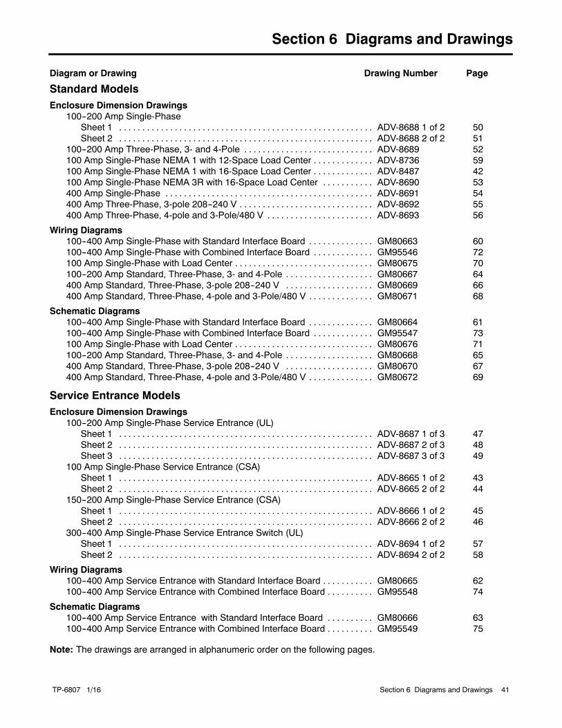
TP-6807 1/16 41Section 6 Diagrams and Drawings
Section 6 Diagrams and Drawings
Diagram or Drawing Drawing Number Page
Standard ModelsEnclosure Dimension Drawings
100--200 Amp Single-PhaseSheet 1 ADV-8688 1 of 2 50. . . . . . . . . . . . . . . . . . . . . . . . . . . . . . . . . . . . . . . . . . . . . . . . . . . . . . .Sheet 2 ADV-8688 2 of 2 51. . . . . . . . . . . . . . . . . . . . . . . . . . . . . . . . . . . . . . . . . . . . . . . . . . . . . . .
100--200 Amp Three-Phase, 3- and 4-Pole ADV-8689 52. . . . . . . . . . . . . . . . . . . . . . . . . . . .100 Amp Single-Phase NEMA 1 with 12-Space Load Center ADV-8736 59. . . . . . . . . . . . .100 Amp Single-Phase NEMA 1 with 16-Space Load Center ADV-8487 42. . . . . . . . . . . . .100 Amp Single-Phase NEMA 3R with 16-Space Load Center ADV-8690 53. . . . . . . . . . .400 Amp Single-Phase ADV-8691 54. . . . . . . . . . . . . . . . . . . . . . . . . . . . . . . . . . . . . . . . . . . . .400 Amp Three-Phase, 3-pole 208--240 V ADV-8692 55. . . . . . . . . . . . . . . . . . . . . . . . . . . . .400 Amp Three-Phase, 4-pole and 3-Pole/480 V ADV-8693 56. . . . . . . . . . . . . . . . . . . . . . .
Wiring Diagrams100--400 Amp Single-Phase with Standard Interface Board GM80663 60. . . . . . . . . . . . . .100--400 Amp Single-Phase with Combined Interface Board GM95546 72. . . . . . . . . . . . .100 Amp Single-Phase with Load Center GM80675 70. . . . . . . . . . . . . . . . . . . . . . . . . . . . . .100--200 Amp Standard, Three-Phase, 3- and 4-Pole GM80667 64. . . . . . . . . . . . . . . . . . .400 Amp Standard, Three-Phase, 3-pole 208--240 V GM80669 66. . . . . . . . . . . . . . . . . . .400 Amp Standard, Three-Phase, 4-pole and 3-Pole/480 V GM80671 68. . . . . . . . . . . . . .
Schematic Diagrams100--400 Amp Single-Phase with Standard Interface Board GM80664 61. . . . . . . . . . . . . .100--400 Amp Single-Phase with Combined Interface Board GM95547 73. . . . . . . . . . . . .100 Amp Single-Phase with Load Center GM80676 71. . . . . . . . . . . . . . . . . . . . . . . . . . . . . .100--200 Amp Standard, Three-Phase, 3- and 4-Pole GM80668 65. . . . . . . . . . . . . . . . . . .400 Amp Standard, Three-Phase, 3-pole 208--240 V GM80670 67. . . . . . . . . . . . . . . . . . .400 Amp Standard, Three-Phase, 4-pole and 3-Pole/480 V GM80672 69. . . . . . . . . . . . . .
Service Entrance ModelsEnclosure Dimension Drawings
100--200 Amp Single-Phase Service Entrance (UL)Sheet 1 ADV-8687 1 of 3 47. . . . . . . . . . . . . . . . . . . . . . . . . . . . . . . . . . . . . . . . . . . . . . . . . . . . . . .Sheet 2 ADV-8687 2 of 3 48. . . . . . . . . . . . . . . . . . . . . . . . . . . . . . . . . . . . . . . . . . . . . . . . . . . . . . .Sheet 3 ADV-8687 3 of 3 49. . . . . . . . . . . . . . . . . . . . . . . . . . . . . . . . . . . . . . . . . . . . . . . . . . . . . . .
100 Amp Single-Phase Service Entrance (CSA)Sheet 1 ADV-8665 1 of 2 43. . . . . . . . . . . . . . . . . . . . . . . . . . . . . . . . . . . . . . . . . . . . . . . . . . . . . . .Sheet 2 ADV-8665 2 of 2 44. . . . . . . . . . . . . . . . . . . . . . . . . . . . . . . . . . . . . . . . . . . . . . . . . . . . . . .
150--200 Amp Single-Phase Service Entrance (CSA)Sheet 1 ADV-8666 1 of 2 45. . . . . . . . . . . . . . . . . . . . . . . . . . . . . . . . . . . . . . . . . . . . . . . . . . . . . . .Sheet 2 ADV-8666 2 of 2 46. . . . . . . . . . . . . . . . . . . . . . . . . . . . . . . . . . . . . . . . . . . . . . . . . . . . . . .
300--400 Amp Single-Phase Service Entrance Switch (UL)Sheet 1 ADV-8694 1 of 2 57. . . . . . . . . . . . . . . . . . . . . . . . . . . . . . . . . . . . . . . . . . . . . . . . . . . . . . .Sheet 2 ADV-8694 2 of 2 58. . . . . . . . . . . . . . . . . . . . . . . . . . . . . . . . . . . . . . . . . . . . . . . . . . . . . . .
Wiring Diagrams100--400 Amp Service Entrance with Standard Interface Board GM80665 62. . . . . . . . . . .100--400 Amp Service Entrance with Combined Interface Board GM95548 74. . . . . . . . . .
Schematic Diagrams100--400 Amp Service Entrance with Standard Interface Board GM80666 63. . . . . . . . . .100--400 Amp Service Entrance with Combined Interface Board GM95549 75. . . . . . . . . .
Note: The drawings are arranged in alphanumeric order on the following pages.

TP-6807 1/1642 Section 5 Diagrams and Drawings
Figure 6-1 Enclosure Dimensions, 100 Amp NEMA 1 with 16-Space Load Center, ADV-8487

TP-6807 1/16 43Section 5 Diagrams and Drawings
Figure 6-2 Enclosure Dimensions, 100 Amp, CSA Certified Service Entrance, ADV-8665, Sheet 1 of 2

TP-6807 1/1644 Section 5 Diagrams and Drawings
Figure 6-3 Enclosure Dimensions, 100 Amp, CSA Certified Service Entrance, ADV-8665, Sheet 2 of 2

TP-6807 1/16 45Section 5 Diagrams and Drawings
Figure 6-4 Enclosure Dimensions, 150--200 Amp CSA Certified Service Entrance, ADV-8666, Sheet 1 of 2

TP-6807 1/1646 Section 5 Diagrams and Drawings
Figure 6-5 Enclosure Dimensions, 150--200 Amp CSA Certified Service Entrance, ADV-8666, Sheet 2 of 2

TP-6807 1/16 47Section 5 Diagrams and Drawings
Figure 6-6 Enclosure Dimensions, 100--200 Amp Single-Phase, Service Entrance, ADV-8687, Sheet 1 of 3

TP-6807 1/1648 Section 5 Diagrams and Drawings
Figure 6-7 Enclosure Dimensions, 100--200 Amp Single-Phase, Service Entrance, ADV-8687, Sheet 2 of 3

TP-6807 1/16 49Section 5 Diagrams and Drawings
Figure 6-8 Enclosure Dimensions, 100--200 Amp Single-Phase, Service Entrance, ADV-8687, Sheet 3 of 3

TP-6807 1/1650 Section 5 Diagrams and Drawings
Figure 6-9 Enclosure Dimensions, 100--200 Amp Single-Phase, ADV-8688, Sheet 1 of 2

TP-6807 1/16 51Section 5 Diagrams and Drawings
Figure 6-10 Enclosure Dimensions, 100--200 Amp Single-Phase, ADV-8688, Sheet 2 of 2

TP-6807 1/1652 Section 5 Diagrams and Drawings
Figure 6-11 Enclosure Dimensions, 100--200 Amp Three-Phase, 3- and 4-Pole, ADV-8689

TP-6807 1/16 53Section 5 Diagrams and Drawings
Figure 6-12 Enclosure Dimensions, 100 Amp Single-Phase with Load Center, ADV-8690
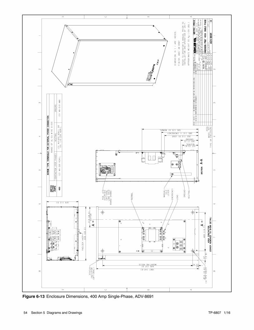
TP-6807 1/1654 Section 5 Diagrams and Drawings
Figure 6-13 Enclosure Dimensions, 400 Amp Single-Phase, ADV-8691
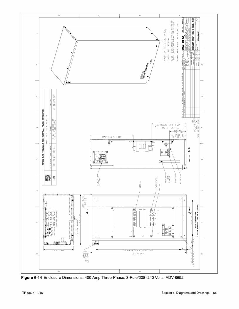
TP-6807 1/16 55Section 5 Diagrams and Drawings
Figure 6-14 Enclosure Dimensions, 400 Amp Three-Phase, 3-Pole/208--240 Volts, ADV-8692
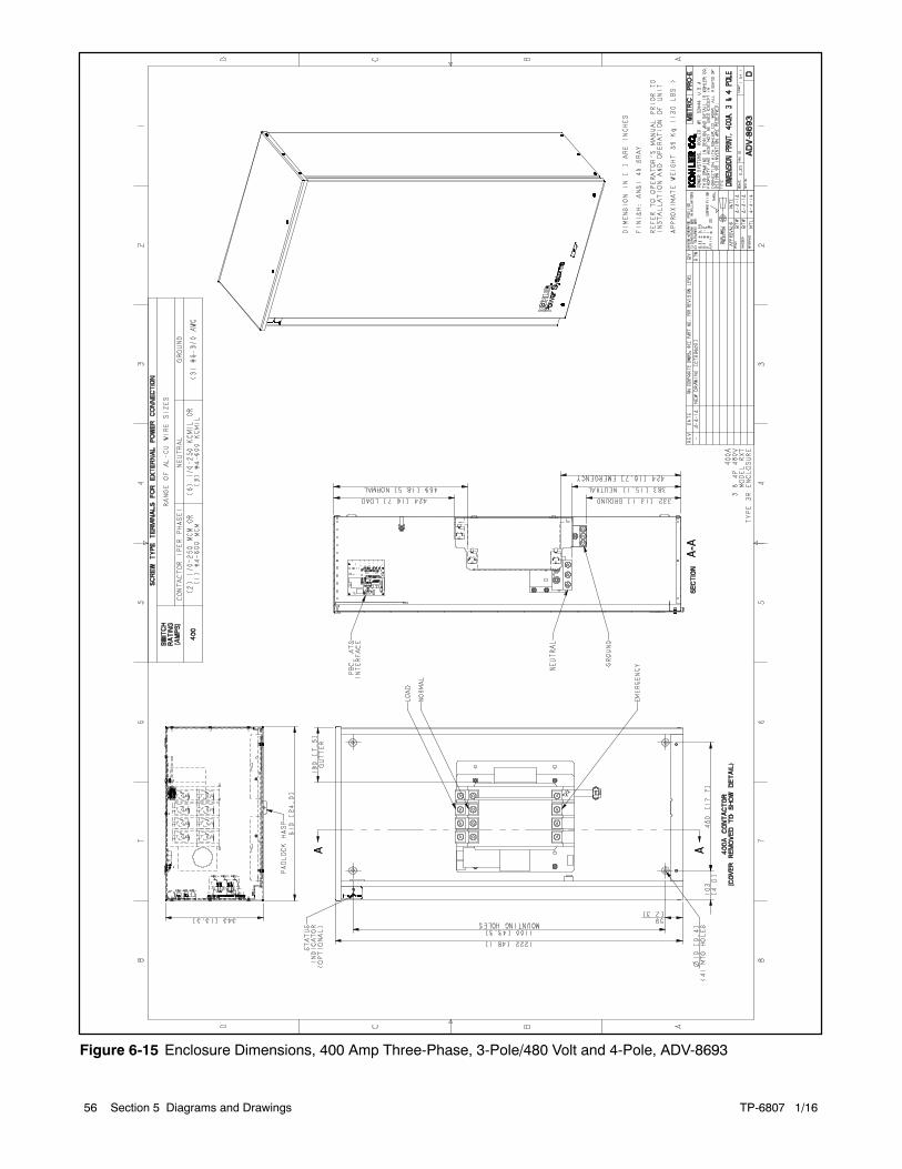
TP-6807 1/1656 Section 5 Diagrams and Drawings
Figure 6-15 Enclosure Dimensions, 400 Amp Three-Phase, 3-Pole/480 Volt and 4-Pole, ADV-8693
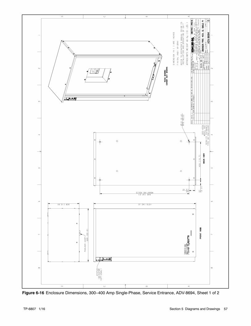
TP-6807 1/16 57Section 5 Diagrams and Drawings
Figure 6-16 Enclosure Dimensions, 300--400 Amp Single-Phase, Service Entrance, ADV-8694, Sheet 1 of 2
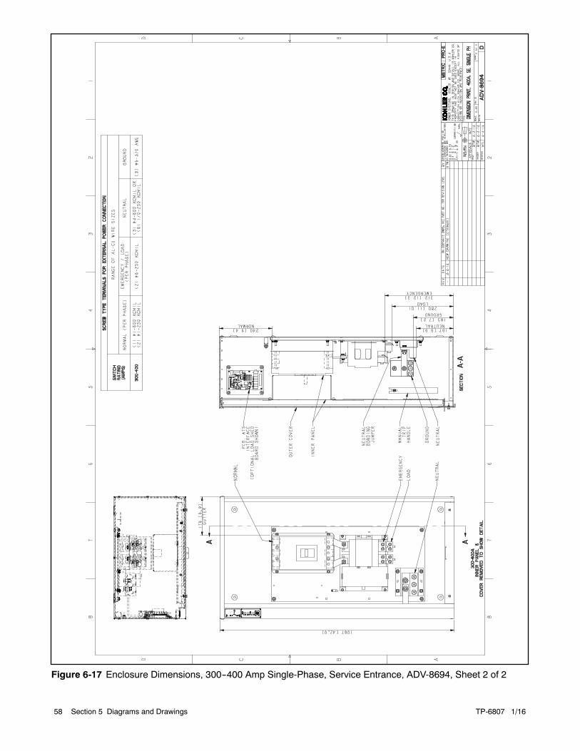
TP-6807 1/1658 Section 5 Diagrams and Drawings
Figure 6-17 Enclosure Dimensions, 300--400 Amp Single-Phase, Service Entrance, ADV-8694, Sheet 2 of 2

TP-6807 1/16 59Section 5 Diagrams and Drawings
Figure 6-18 Enclosure Dimensions, 100 Amp NEMA 1 with 12-Space Load Center, ADV-8736

TP-6807 1/1660 Section 5 Diagrams and Drawings
Figure 6-19 Wiring Diagram, 100--400 Amp Single-Phase, GM80663

TP-6807 1/16 61Section 5 Diagrams and Drawings
Figure 6-20 Schematic Diagram, 100--400 Amp Single-Phase, GM80664

TP-6807 1/1662 Section 5 Diagrams and Drawings
Figure 6-21 Wiring Diagram, 100--400 Amp Service Entrance, GM80665

TP-6807 1/16 63Section 5 Diagrams and Drawings
Figure 6-22 Schematic Diagram, 100--400 Amp Service Entrance, GM80666

TP-6807 1/1664 Section 5 Diagrams and Drawings
Figure 6-23 Wiring Diagram, 100--200 Amp Three-Phase, 3- and 4-Pole, GM80667

TP-6807 1/16 65Section 5 Diagrams and Drawings
Figure 6-24 Schematic Diagram, 100--200 Amp Three-Phase, 3- and 4-Pole, GM80668

TP-6807 1/1666 Section 5 Diagrams and Drawings
Figure 6-25 Wiring Diagram, 400 Amp Three-Phase, 3-Pole/208--240 Volts, GM80669

TP-6807 1/16 67Section 5 Diagrams and Drawings
Figure 6-26 Schematic Diagram, 400 Amp Three-Phase, 3-Pole/208--240 Volts, GM80670

TP-6807 1/1668 Section 5 Diagrams and Drawings
Figure 6-27 Wiring Diagram, 400 Amp Three-Phase, 3-Pole/480 Volts and 4-Pole, GM80671

TP-6807 1/16 69Section 5 Diagrams and Drawings
Figure 6-28 Schematic Diagram, 400 Amp Three-Phase, 3-Pole/480 Volts and 4-Pole, GM80672
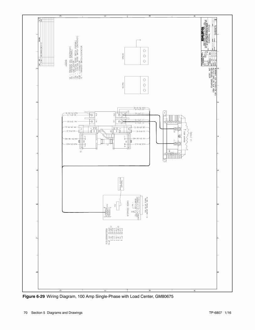
TP-6807 1/1670 Section 5 Diagrams and Drawings
Figure 6-29 Wiring Diagram, 100 Amp Single-Phase with Load Center, GM80675
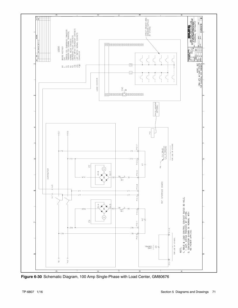
TP-6807 1/16 71Section 5 Diagrams and Drawings
Figure 6-30 Schematic Diagram, 100 Amp Single-Phase with Load Center, GM80676

TP-6807 1/1672 Section 5 Diagrams and Drawings
Figure 6-31 Wiring Diagram, 100--400 Amp Single-Phase with Combined Interface Board, GM95546

TP-6807 1/16 73Section 5 Diagrams and Drawings
Figure 6-32 Schematic Diagram, 100--400 Amp Single-Phase with Combined Interface Board, GM95547
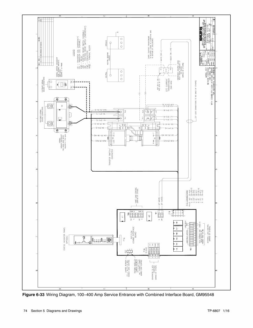
TP-6807 1/1674 Section 5 Diagrams and Drawings
Figure 6-33 Wiring Diagram, 100--400 Amp Service Entrance with Combined Interface Board, GM95548

TP-6807 1/16 75Section 5 Diagrams and Drawings
Figure 6-34 Schematic Diagram, 100--400 Amp Service Entrance with Combined Interface Board, GM95549

TP-6807 1/1676 Section 5 Diagrams and Drawings
Notes

TP-6807 1/16 Appendix 77
Appendix A Abbreviations
The following list contains abbreviations that may appear in this publication.
A, amp ampereABDC after bottom dead centerAC alternating currentA/D analog to digitalADC advanced digital control;
analog to digital converteradj. adjust, adjustmentADV advertising dimensional
drawingAh amp-hourAHWT anticipatory high water
temperatureAISI American Iron and Steel
InstituteALOP anticipatory low oil pressurealt. alternatorAl aluminumANSI American National Standards
Institute (formerly AmericanStandards Association, ASA)
AO anticipatory onlyAPDC Air Pollution Control DistrictAPI American Petroleum Instituteapprox. approximate, approximatelyAQMD Air Quality Management DistrictAR as required, as requestedAS as supplied, as stated, as
suggestedASE American Society of EngineersASME American Society of
Mechanical Engineersassy. assemblyASTM American Society for Testing
MaterialsATDC after top dead centerATS automatic transfer switchauto. automaticaux. auxiliaryavg. averageAVR automatic voltage regulatorAWG American Wire GaugeAWM appliance wiring materialbat. batteryBBDC before bottom dead centerBC battery charger, battery
chargingBCA battery charging alternatorBCI Battery Council InternationalBDC before dead centerBHP brake horsepowerblk. black (paint color), block
(engine)blk. htr. block heaterBMEP brake mean effective pressurebps bits per secondbr. brassBTDC before top dead centerBtu British thermal unitBtu/min. British thermal units per minuteC Celsius, centigradecal. calorieCAN controller area networkCARB California Air Resources BoardCB circuit breakercc cubic centimeterCCA cold cranking ampsccw. counterclockwiseCEC Canadian Electrical Codecert. certificate, certification, certifiedcfh cubic feet per hour
cfm cubic feet per minuteCG center of gravityCID cubic inch displacementCL centerlinecm centimeterCMOS complementary metal oxide
substrate (semiconductor)cogen. cogenerationcom communications (port)coml commercialComl/Rec Commercial/Recreationalconn. connectioncont. continuedCPVC chlorinated polyvinyl chloridecrit. criticalCRT cathode ray tubeCSA Canadian Standards
AssociationCT current transformerCu coppercUL Canadian Underwriter’s
LaboratoriesCUL Canadian Underwriter’s
Laboratoriescu. in. cubic inchcw. clockwiseCWC city water-cooledcyl. cylinderD/A digital to analogDAC digital to analog converterdB decibeldB(A) decibel (A weighted)DC direct currentDCR direct current resistancedeg., degreedept. departmentDFMEA Design Failure Mode and
Effects Analysisdia. diameterDI/EO dual inlet/end outletDIN Deutsches Institut fur Normung
e. V. (also Deutsche IndustrieNormenausschuss)
DIP dual inline packageDPDT double-pole, double-throwDPST double-pole, single-throwDS disconnect switchDVR digital voltage regulatorE, emer. emergency (power source)ECM electronic control module,
engine control moduleEDI electronic data interchangeEFR emergency frequency relaye.g. for example (exempli gratia)EG electronic governorEGSA Electrical Generating Systems
AssociationEIA Electronic Industries
AssociationEI/EO end inlet/end outletEMI electromagnetic interferenceemiss. emissioneng. engineEPA Environmental Protection
AgencyEPS emergency power systemER emergency relayES engineering special,
engineered specialESD electrostatic discharge
est. estimatedE-Stop emergency stopetc. et cetera (and so forth)exh. exhaustext. externalF Fahrenheit, femalefglass. fiberglassFHM flat head machine (screw)fl. oz. fluid ounceflex. flexiblefreq. frequencyFS full scaleft. foot, feetft. lb. foot pounds (torque)ft./min. feet per minuteftp file transfer protocolg gramga. gauge (meters, wire size)gal. gallongen. generatorgenset generator setGFI ground fault interrupter
GND, groundgov. governorgph gallons per hourgpm gallons per minutegr. grade, grossGRD equipment groundgr. wt. gross weightH x W x D height by width by depthHC hex capHCHT high cylinder head temperatureHD heavy dutyHET high exhaust temp., high
engine temp.hex hexagonHg mercury (element)HH hex headHHC hex head capHP horsepowerhr. hourHS heat shrinkhsg. housingHVAC heating, ventilation, and air
conditioningHWT high water temperatureHz hertz (cycles per second)IC integrated circuitID inside diameter, identificationIEC International Electrotechnical
CommissionIEEE Institute of Electrical and
Electronics EngineersIMS improved motor startingin. inchin. H2O inches of waterin. Hg inches of mercuryin. lb. inch poundsInc. incorporatedind. industrialint. internalint./ext. internal/externalI/O input/outputIP iron pipeISO International Organization for
StandardizationJ jouleJIS Japanese Industry Standard

TP-6807 1/1678 Appendix
k kilo (1000)K kelvinkA kiloampereKB kilobyte (210 bytes)KBus Kohler communication protocolkg kilogramkg/cm2 kilograms per square
centimeterkgm kilogram-meterkg/m3 kilograms per cubic meterkHz kilohertzkJ kilojoulekm kilometerkOhm, k kilo-ohmkPa kilopascalkph kilometers per hourkV kilovoltkVA kilovolt amperekVAR kilovolt ampere reactivekW kilowattkWh kilowatt-hourkWm kilowatt mechanicalkWth kilowatt-thermalL literLAN local area networkL x W x H length by width by heightlb. pound, poundslbm/ft3 pounds mass per cubic feetLCB line circuit breakerLCD liquid crystal displayld. shd. load shedLED light emitting diodeLph liters per hourLpm liters per minuteLOP low oil pressureLP liquefied petroleumLPG liquefied petroleum gasLS left sideLwa sound power level, A weightedLWL low water levelLWT low water temperaturem meter, milli (1/1000)M mega (106 when used with SI
units), malem3 cubic meterm3/hr. cubic meters per hourm3/min. cubic meters per minutemA milliampereman. manualmax. maximumMB megabyte (220 bytes)MCCB molded-case circuit breakerMCM one thousand circular milsmeggar megohmmeterMHz megahertzmi. milemil one one-thousandth of an inchmin. minimum, minutemisc. miscellaneousMJ megajoulemJ millijoulemm millimetermOhm, mmilliohmMOhm, MmegohmMOV metal oxide varistorMPa megapascalmpg miles per gallonmph miles per hourMS military standardms millisecondm/sec. meters per secondMTBF mean time between failure
MTBO mean time between overhaulsmtg. mountingMTU Motoren-und Turbinen-UnionMW megawattmW milliwattF microfaradN, norm. normal (power source)NA not available, not applicablenat. gas natural gasNBS National Bureau of StandardsNC normally closedNEC National Electrical CodeNEMA National Electrical
Manufacturers AssociationNFPA National Fire Protection
AssociationNm newton meterNO normally openno., nos. number, numbersNPS National Pipe, StraightNPSC National Pipe, Straight-couplingNPT National Standard taper pipe
thread per general useNPTF National Pipe, Taper-FineNR not required, normal relayns nanosecondOC overcrankOD outside diameterOEM original equipment
manufacturerOF overfrequencyopt. option, optionalOS oversize, overspeedOSHA Occupational Safety and Health
AdministrationOV overvoltageoz. ouncep., pp. page, pagesPC personal computerPCB printed circuit boardpF picofaradPF power factorph., phasePHC Phillipsr head Crimptiter
(screw)PHH Phillipsr hex head (screw)PHM pan head machine (screw)PLC programmable logic controlPMG permanent magnet generatorpot potentiometer, potentialppm parts per millionPROM programmable read-only
memorypsi pounds per square inchpsig pounds per square inch gaugept. pintPTC positive temperature coefficientPTO power takeoffPVC polyvinyl chlorideqt. quart, quartsqty. quantityR replacement (emergency)
power sourcerad. radiator, radiusRAM random access memoryRDO relay driver outputref. referencerem. remoteRes/Coml Residential/CommercialRFI radio frequency interferenceRH round headRHM round head machine (screw)rly. relay
rms root mean squarernd. roundROM read only memoryrot. rotate, rotatingrpm revolutions per minuteRS right sideRTU remote terminal unitRTV room temperature vulcanizationRW read/writeSAE Society of Automotive
Engineersscfm standard cubic feet per minuteSCR silicon controlled rectifiers, sec. secondSI Systeme international d’unites,
International System of UnitsSI/EO side in/end outsil. silencerSN serial numberSNMP simple network management
protocolSPDT single-pole, double-throwSPST single-pole, single-throwspec specificationspecs specification(s)sq. squaresq. cm square centimetersq. in. square inchSS stainless steelstd. standardstl. steeltach. tachometerTD time delayTDC top dead centerTDEC time delay engine cooldownTDEN time delay emergency to
normalTDES time delay engine startTDNE time delay normal to
emergencyTDOE time delay off to emergencyTDON time delay off to normaltemp. temperatureterm. terminalTHD total harmonic distortionTIF telephone influence factorTIR total indicator readingtol. toleranceturbo. turbochargertyp. typical (same in multiple
locations)UF underfrequencyUHF ultrahigh frequencyUL Underwriter’s Laboratories, Inc.UNC unified coarse thread (was NC)UNF unified fine thread (was NF)univ. universalUS undersize, underspeedUV ultraviolet, undervoltageV voltVAC volts alternating currentVAR voltampere reactiveVDC volts direct currentVFD vacuum fluorescent displayVGA video graphics adapterVHF very high frequencyW wattWCR withstand and closing ratingw/ withw/o withoutwt. weightxfmr transformer


E 2011, 2014, 2015, 2016 by Kohler Co. All rights reserved.
TP-6807 1/16d
KOHLER CO. Kohler, Wisconsin 53044Phone 920-457-4441, Fax 920-459-1646For the nearest sales/service outlet in theUS and Canada, phone 1-800-544-2444KOHLERPower.com
Kohler Power SystemsAsia Pacific Headquarters7 Jurong Pier RoadSingapore 619159Phone (65) 6264-6422, Fax (65) 6264-6455