automatic sprinklers chapter 1 - fire notes · pdf file4 chapter 1 automatic sprinklers...
TRANSCRIPT
3
NFPA statistics indicate that sprinkler systems function exceptionally well when prop-erly maintained. The few instances of system failure are found to be directly related to shut water supply control valves and inadequate maintenance, which can be con-strued as a misunderstanding of the operational needs of the system. Commissioning, beginning in the planning stages of a construction project, is intended not only to address the operational requirements for sprinkler systems but to also provide for the documentation of the concepts employed in the system design and the installa-tion and testing of the system. This documentation, when combined with appropri-ate training during project closeout, is intended to ensure peak system performance throughout the life cycle of the building and system.
This chapter provides excerpts from NFPA 13, Standard for the Installation of Sprin-kler Systems, that directly relate to the commissioning of sprinkler systems. The chapter begins with a discussion of plans and calculations and concludes with testing require-ments and project closeout documentation.
OVERVIEWAutomatic Sprinkler System Defined
A sprinkler system can be described as a system employing automatic sprinklers attached to a piping system containing water and connected to a water supply so that water dis-charges immediately from sprinklers opened by heat from a fire (commonly referred to as a wet-pipe system). For unheated spaces, such a system employs automatic sprinklers attached to a piping system containing air or nitrogen under pressure.
The release of this air or nitrogen (as from the opening of a sprinkler) permits the water pressure to open a dry-pipe valve, and the water then flows into the piping system and out of the opened sprinklers (a dry-pipe system).
For high hazard areas, a deluge sprinkler system employs open sprinklers attached to a piping system connected to a water supply through a valve. The valve is opened by the opera-tion of a detection system installed in the same areas as the sprinklers. When this valve opens, water flows into the piping system and discharges from all sprinklers attached thereto.
A preaction sprinkler system employs automatic sprinklers attached to a piping sys-tem containing air that may or may not be under pressure. A supplemental detection system is installed in the same areas as the sprinklers.
Each of these system types will have specific commissioning requirements, because each employs different types of valves and activation mechanisms.
CHAPTER
1Automatic Sprinklers

4 Chapter 1 ● Automatic Sprinklers
Program for Individual Systems
Level of Protection
NFPA 13 requires protection of all areas of a building with only specific omissions allowed, such as noncombustible concealed spaces. The basis of design (BOD), project specifica-tions, and preliminary plans should clearly document areas where sprinklers are omitted.
A building, where protected by an automatic sprinkler system installation, shall be provided with sprinklers in all areas except where specifi c sections of this standard permit the omission of sprinklers. [NFPA 13-10: 4.1]
When partial sprinkler systems are installed, the requirements of this standard shall be used insofar as they are applicable. [NFPA 13-10: 4.2.1]
The authority having jurisdiction shall be consulted in each case. [NFPA 13-10: 4.2.2]
Owner Requirements
The owner(s) of a building or structure where the fi re sprinkler system is going to be installed or their authorized agent shall provide the sprinkler system installer with the following information prior to the layout and detailing of the fi re sprinkler system [see NFPA 13-10: Figure A.22.1(b)] [Exhibit 1.1]:
(1) Intended use of the building including the materials within the building and the maximum height of any storage
(2) A preliminary plan of the building or structure along with the design concepts necessary to perform the layout and detail for the fire sprinkler system
(3) Any special knowledge of the water supply, including known environmental conditions that might be responsible for corrosion, including microbiologically influenced corrosion (MIC) [NFPA 13-10: 4.3]
For new construction, this information is sent to the registered design professional (RDP) for inclusion in the project plans and specifications. This information is used to develop the BOD documentation. Exhibit 1.1 can be included as a section of the BOD.
PLANSConstruction Documents Defined
Documents that consist of scaled design drawings and specifi cations for the pur-pose of construction of new facilities or modifi cation to existing facilities. [NFPA 1-12: 3.3.69]
Preliminary Plans
Preliminary plans should be submitted for review to the authority having ju-risdiction prior to the development of working plans [see NFPA 13-10: Figure
A.22.1(a)][Exhibit 1.2]. The preliminary plans can be part of the construction docu-ments submitted in order to obtain a building permit. However, working drawings in accordance with Section 22.1 should be submitted and approved prior to the installa-tion of system equipment. Preliminary plans should include as much information as is required to provide a clear representation of the hazard to be protected, the system design concept, the proposed water supply confi guration, and building construction information pertinent to system layout and detailing.
The owner’s information certificate [see NFPA 13-10: Figure A.22.1(b)][Exhibit 1.1]: should be used to obtain a declaration of the intended use of the occupancy to be protected. Drawings that accompany the certificate should include the following:
13
13
1
13 A

Chapter 1 ● Automatic Sprinklers 5
Program for Individual Systems
EXHIBIT 1.1 Owner’s Information Certifi cate Source: Adapted from NFPA 13, 2010, Figure A.14.1(b).
NFPA 13 (p. 1 of 2)© 2009 National Fire Protection Association
OWNER’S INFORMATION CERTIFICATE
Name/address of property to be protected with sprinkler protection:
Name of owner:
Existing or planned construction is:
❏ Fire resistive or noncombustible
❏ Wood frame or ordinary (masonry walls with wood beams)
❏ Unknown
Describe the intended use of the building:
Note regarding speculative buildings: The design and installation of the fire sprinkler system is dependent on an accurate description of the likely use of the building. Without specific information, assumptions will need to be made that will limit the actual use of the building. Make sure that you communicate any and all use considerations to the fire sprinkler contractor in this form and that you abide by all limitations regarding the use of the building based on the limitations of the fire sprinkler system that is eventually designed and installed.
Is the system installation intended for one of the following special occupancies:
Aircraft hangar ❏ Yes ❏ No Fixed guideway transit system ❏ Yes ❏ No Race track stable ❏ Yes ❏ No Marine terminal, pier, or wharf ❏ Yes ❏ No Airport terminal ❏ Yes ❏ No Aircraft engine test facility ❏ Yes ❏ No Power plant ❏ Yes ❏ No Water-cooling tower ❏ Yes ❏ No
If the answer to any of the above is “yes,” the appropriate NFPA standard should be referenced for sprinkler density/area criteria.
Indicate whether any of the following special materials are intended to be present:
Flammable or combustible liquids ❏ Yes ❏ No Aerosol products ❏ Yes ❏ No Nitrate film ❏ Yes ❏ No Pyroxylin plastic ❏ Yes ❏ No Compressed or liquefied gas cylinders ❏ Yes ❏ No Liquid or solid oxidizers ❏ Yes ❏ No Organic peroxide formulations ❏ Yes ❏ No Idle pallets ❏ Yes ❏ No
If the answer to any of the above is “yes,” describe type, location, arrangement, and intended maximum quantities.

6 Chapter 1 ● Automatic Sprinklers
Program for Individual Systems
EXHIBIT 1.1 Continued
NFPA 13 (p. 2 of 2)© 2009 National Fire Protection Association
Indicate whether the protection is intended for one of the following specialized occupancies or areas:
Spray area or mixing room ❏ Yes ❏ No Solvent extraction ❏ Yes ❏ No Laboratory using chemicals ❏ Yes ❏ No Oxygen-fuel gas system for welding or cutting ❏ Yes ❏ No Acetylene cylinder charging ❏ Yes ❏ No Production or use of compressed or liquefied gases ❏ Yes ❏ No Commercial cooking operation ❏ Yes ❏ No Class A hyperbaric chamber ❏ Yes ❏ No Cleanroom ❏ Yes ❏ No Incinerator or waste handling system ❏ Yes ❏ No Linen handling system ❏ Yes ❏ No Industrial furnace ❏ Yes ❏ No Water-cooling tower ❏ Yes ❏ No
If the answer to any of the above is “yes,” describe type, location, arrangement, and intended maximum quantities.
Will there be any storage of products over 12 ft (3.6 m) in height? ❏ Yes ❏ No
If the answer is “yes,” describe product, intended storage arrangement, and height.
Will there be any storage of plastic, rubber, or similar products over 5 ft (1.5 m) high except as described above? ❏ Yes ❏ No
If the answer is “yes,” describe product, intended storage arrangement, and height.
Is there any special information concerning the water supply? ❏ Yes ❏ No
If the answer is “yes,” provide the information, including known environmental conditions that might be responsiblefor corrosion, including microbiologically influenced corrosion (MIC).
I certify that I have knowledge of the intended use of the property and that the above information is correct.
Signature of owner’s representative or agent: Date:
Name of owner’s representative or agent completing certificate (print):
Relationship and firm of agent (print):
Chapter 1 ● Automatic Sprinklers 7
Program for Individual Systems
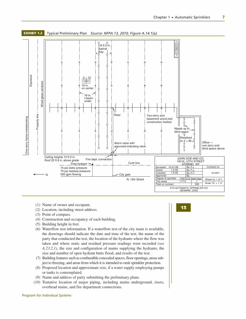
EXHIBIT 1.2 Typical Preliminary Plan Source: NFPA 13, 2010, Figure A.14.1(a).
(1) Name of owner and occupant. (2) Location, including street address. (3) Point of compass. (4) Construction and occupancy of each building. (5) Building height in feet. (6) Waterflow test information. If a waterflow test of the city main is available,
the drawings should indicate the date and time of the test, the name of the party that conducted the test, the location of the hydrants where the flow was taken and where static and residual pressure readings were recorded (see A.23.2.1), the size and configuration of mains supplying the hydrants, the size and number of open hydrant butts flood, and results of the test.
(7) Building features such as combustible concealed spaces, floor openings, areas sub-ject to freezing, and areas from which it is intended to omit sprinkler protection.
(8) Proposed location and approximate size, if a water supply employing pumps or tanks is contemplated.
(9) Name and address of party submitting the preliminary plans. (10) Tentative location of major piping, including mains underground, risers,
overhead mains, and fire department connections.
2 ¥ 12
16 in.on center
18 in. I-beamunder
Two-story and basement wood joistconstruction heated
75 psi static pressure70 psi residual pressure 500 gpm flowing
Flow hydrant
N
Ceiling heights 10 ft 0 in.Roof 22 ft 6 in. above grade Fire dept. connection
Curb line
City gate
N. 12th Street
Alarm valve withapproved indicating valve
One
-sto
ry fr
ame-
met
alw
orki
ng
Pro
pert
y lin
e
Wire
dgl
ass
win
dow
s
Exp
osur
e
Riser
Sheathed on 2 ¥ 90.J. Office —
one story and blind space above
Nipple up toblind space
16 ft 0 in.typical bay
JOHN DOE AND CO.100 N. 12TH STREET
STRAND, NYSurveyed 12-31-08Drawn 1-4-09Checked 1-5-09ApprovedDegree of sprinklerThis sheetTotal on contract
XYZ AUTOMATIC SPRINKLER CO.NEWARK, OHIO
160∞ 212∞ 280∞ 360∞171
528
Contract no.
N-4341
Sheet no. 1 of 1
Scale ¹⁄₈" = 1' 0"
By: F.J.By: F.J.By: H.T.By:
13
8 Chapter 1 ● Automatic Sprinklers
Program for Individual Systems
The preliminary plan discussed here is usually submitted by the RDP with the complete set of bid documents for the project. This set ordinarily includes the architectural, structural plans and all building systems, such as electrical; plumbing; heating, ventilation, and air conditioning (HVAC); fire protection; and so on. The preliminary plans should include suf-ficient information to permit an initial plan review for the issuance of a building permit.
Working Plans
Working plans are much more detailed than preliminary plans. As the name suggests, these are the plans normally used for installation and submission as the final as-built drawings during project closeout. They must, therefore, contain exact dimensions and instructions for the installer.
These plans can also be used for the fabrication of precut pipe and pipe supports. Ordinarily, sprinkler pipe is fabricated in a fabrication shop off-site and shipped to the project with pipe lengths cut based on the dimensions shown on the working drawing; pipe threads are fabricated onto the pipe and one fitting “made-on” or attached. The sprinkler system is assembled based on the order of installation indicated on the working plans with few, if any, deviations.
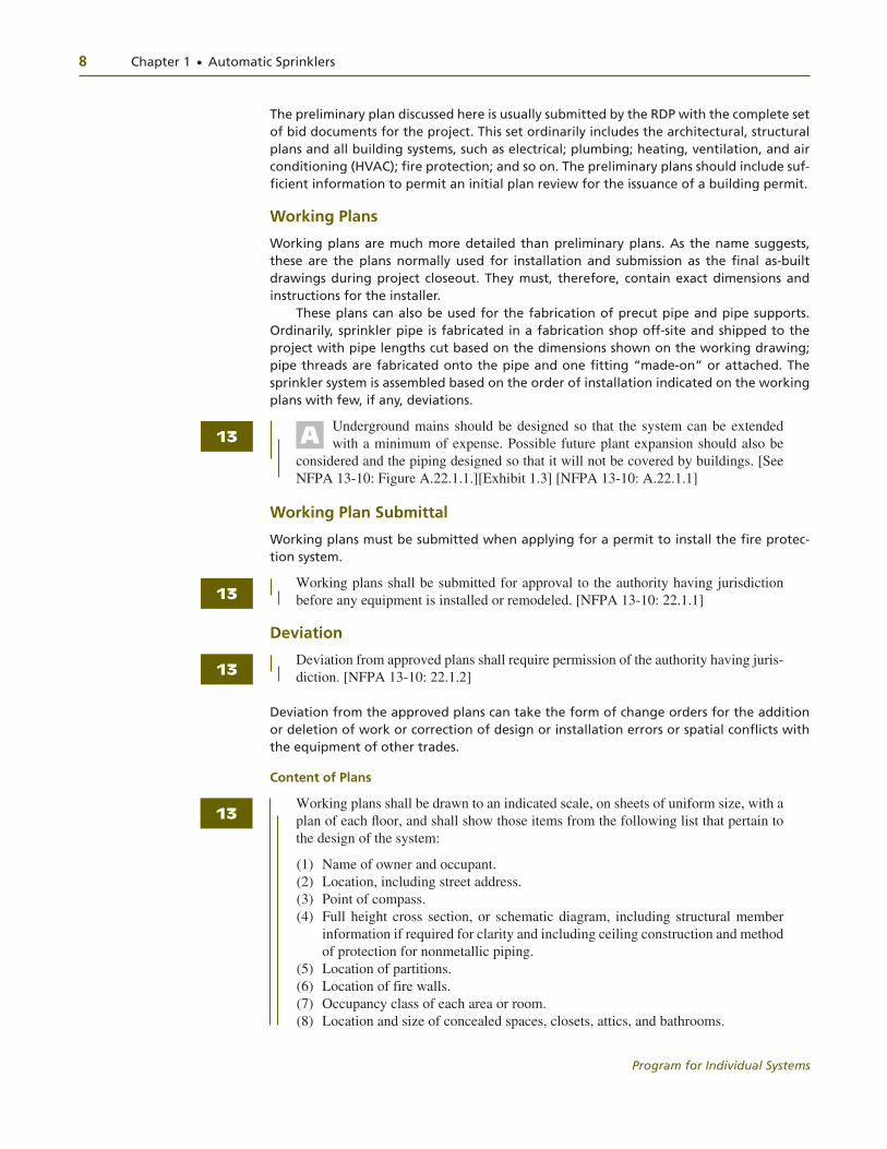
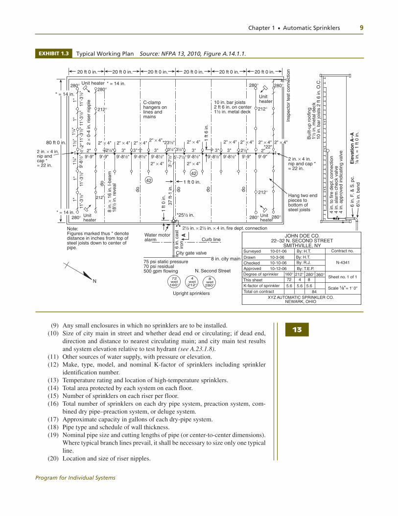
Underground mains should be designed so that the system can be extended with a minimum of expense. Possible future plant expansion should also be
considered and the piping designed so that it will not be covered by buildings. [See NFPA 13-10: Figure A.22.1.1.][Exhibit 1.3] [NFPA 13-10: A.22.1.1]
Working Plan Submittal
Working plans must be submitted when applying for a permit to install the fire protec-tion system.
Working plans shall be submitted for approval to the authority having jurisdiction before any equipment is installed or remodeled. [NFPA 13-10: 22.1.1]
Deviation
Deviation from approved plans shall require permission of the authority having juris-diction. [NFPA 13-10: 22.1.2]
Deviation from the approved plans can take the form of change orders for the addition or deletion of work or correction of design or installation errors or spatial conflicts with the equipment of other trades.
Content of Plans
Working plans shall be drawn to an indicated scale, on sheets of uniform size, with a plan of each fl oor, and shall show those items from the following list that pertain to the design of the system:
(1) Name of owner and occupant. (2) Location, including street address. (3) Point of compass. (4) Full height cross section, or schematic diagram, including structural member
information if required for clarity and including ceiling construction and method of protection for nonmetallic piping.
(5) Location of partitions. (6) Location of fire walls. (7) Occupancy class of each area or room. (8) Location and size of concealed spaces, closets, attics, and bathrooms.
13
13
13
13
A
Chapter 1 ● Automatic Sprinklers 9
Program for Individual Systems
(9) Any small enclosures in which no sprinklers are to be installed. (10) Size of city main in street and whether dead end or circulating; if dead end,
direction and distance to nearest circulating main; and city main test results and system elevation relative to test hydrant (see A.23.1.8).
(11) Other sources of water supply, with pressure or elevation. (12) Make, type, model, and nominal K-factor of sprinklers including sprinkler
identification number. (13) Temperature rating and location of high-temperature sprinklers. (14) Total area protected by each system on each floor. (15) Number of sprinklers on each riser per floor. (16) Total number of sprinklers on each dry pipe system, preaction system, com-
bined dry pipe–preaction system, or deluge system. (17) Approximate capacity in gallons of each dry-pipe system. (18) Pipe type and schedule of wall thickness. (19) Nominal pipe size and cutting lengths of pipe (or center-to-center dimensions).
Where typical branch lines prevail, it shall be necessary to size only one typical line.
(20) Location and size of riser nipples.
11'-3
¹⁄₂"
1"
1"
1¹⁄₄"
1"
2" ¥ 4"
• • • • • • • • • • • •
42
do do do do
do
* = 14 in.280∞
1"
1¹⁄₄"
212o
9'-8¹⁄₂"
3'-7
¹⁄₂"
2" ¥ 4"
42
8 in
.¥ 1
6 in
. I-b
eam
18¹⁄₂
in. r
evea
l
2¹⁄₂" 3¹⁄₂"3"2 in. ¥ 4 in. nip and cap * = 22 in.
80 ft 0 in.
212∞
9'-8
¹⁄₂"
2"1'-2
"
* = 14 in.
11'-3
¹⁄₂"
280∞280∞
* = 14 in.Unit heater2 ¥
0-4
in. r
iser
nip
ple C-clamp
hangers on lines and mains
20 ft 0 in.
A
280∞
212∞
1 ft
6 in
.
*23¹⁄₂"
Unit heater
280∞
2" ¥ 4"*22"
2 in. ¥ 4 in. nip and cap * = 22 in.
1 ft 0 in.
1 ft
0 in
.37
ft-1
in.
*25¹⁄₂ in.
2¹⁄₂ in. ¥ 2¹⁄₂ in. ¥ 4 in. fire dept. connection
Curb line
AWater motoralarm
City gate valve
75 psi static pressure70 psi residual500 gpm flowing N. Second Street
72 wet 160∞
4 wet 212∞
8 wet 280∞
Upright sprinklers
Note: Figures marked thus * denotedistance in inches from top ofsteel joists down to center ofpipe.
N
212∞
280∞ 280∞Unit heater
Hang two endpieces to bottom of steel joists
Insp
ecto
r te
st c
onne
ctio
n
Bui
lt-up
roo
fing
1¹⁄₂ in
. met
al d
eck
10 in
. bar
jois
ts 2
ft 6
in. O
.C.
Ele
vati
on
A–A
¹⁄₈
in. =
1 ft
0 in
.
4 in
. to
fire
dept
. con
nect
ion
4 in
. ala
rm c
heck
val
ve4
in. a
ppro
ved
indi
catin
g va
lve
6 in
. F. &
S. p
c.6¹
⁄₄ in
. ben
d
20 ft 0 in. 20 ft 0 in. 20 ft 0 in. 20 ft 0 in. 20 ft 0 in.
Unit heater
6 in
. cas
t iro
n
Scale ¹⁄₈"= 1' 0"
JOHN DOE CO.22–32 N. SECOND STREET
SMITHVILLE, NYSurveyed 10-01-06
Drawn 10-3-06Checked 10-10-06ApprovedDegree of sprinkler
K-factor of sprinklerTotal on contract
XYZ AUTOMATIC SPRINKLER CO.NEWARK, OHIO
160∞ 212∞ 280∞ 360∞
5.684
Contract no.
N-4341
Sheet no. 1 of 1
By: H.T.By: H.T.By: R.J.
By: T.E.P.
8 in. city main
10-12-06
This sheet 72 4 8
5.6 5.6
10 in. bar joists2 ft 6 in. on center1¹⁄₂ in. metal deck
9'-9"9'-9" 9'-8¹⁄₂" 9'-8¹⁄₂" 9'-8¹⁄₂" 9'-8¹⁄₂"
2" ¥ 4"
9'-8¹⁄₂" 9'-9"9'-9"
2" ¥ 4"2" ¥ 4"2" ¥ 4"2" ¥ 4"2" ¥ 4"2" ¥ 4"2" ¥ 4"
3" 3" 3¹⁄₂"
5'-7¹⁄₂"
3" 3" 3" 2"2¹⁄₂"
1¹⁄₂"
11'-3
¹⁄₂"
11'-3
¹⁄₂"
11'-3
¹⁄₂"
13
EXHIBIT 1.3 Typical Working Plan Source: NFPA 13, 2010, Figure A.14.1.1.
10 Chapter 1 ● Automatic Sprinklers
Program for Individual Systems
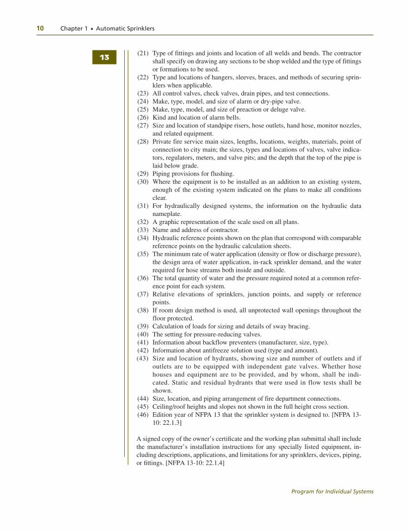
(21) Type of fittings and joints and location of all welds and bends. The contractor shall specify on drawing any sections to be shop welded and the type of fittings or formations to be used.
(22) Type and locations of hangers, sleeves, braces, and methods of securing sprin-klers when applicable.
(23) All control valves, check valves, drain pipes, and test connections. (24) Make, type, model, and size of alarm or dry-pipe valve. (25) Make, type, model, and size of preaction or deluge valve. (26) Kind and location of alarm bells. (27) Size and location of standpipe risers, hose outlets, hand hose, monitor nozzles,
and related equipment. (28) Private fire service main sizes, lengths, locations, weights, materials, point of
connection to city main; the sizes, types and locations of valves, valve indica-tors, regulators, meters, and valve pits; and the depth that the top of the pipe is laid below grade.
(29) Piping provisions for flushing. (30) Where the equipment is to be installed as an addition to an existing system,
enough of the existing system indicated on the plans to make all conditions clear.
(31) For hydraulically designed systems, the information on the hydraulic data nameplate.
(32) A graphic representation of the scale used on all plans. (33) Name and address of contractor. (34) Hydraulic reference points shown on the plan that correspond with comparable
reference points on the hydraulic calculation sheets. (35) The minimum rate of water application (density or flow or discharge pressure),
the design area of water application, in-rack sprinkler demand, and the water required for hose streams both inside and outside.
(36) The total quantity of water and the pressure required noted at a common refer-ence point for each system.
(37) Relative elevations of sprinklers, junction points, and supply or reference points.
(38) If room design method is used, all unprotected wall openings throughout the floor protected.
(39) Calculation of loads for sizing and details of sway bracing. (40) The setting for pressure-reducing valves. (41) Information about backflow preventers (manufacturer, size, type). (42) Information about antifreeze solution used (type and amount). (43) Size and location of hydrants, showing size and number of outlets and if
outlets are to be equipped with independent gate valves. Whether hose houses and equipment are to be provided, and by whom, shall be indi-cated. Static and residual hydrants that were used in flow tests shall be shown.
(44) Size, location, and piping arrangement of fire department connections. (45) Ceiling/roof heights and slopes not shown in the full height cross section. (46) Edition year of NFPA 13 that the sprinkler system is designed to. [NFPA 13-
10: 22.1.3]
A signed copy of the owner’s certifi cate and the working plan submittal shall include the manufacturer’s installation instructions for any specially listed equipment, in-cluding descriptions, applications, and limitations for any sprinklers, devices, piping, or fi ttings. [NFPA 13-10: 22.1.4]
13
Chapter 1 ● Automatic Sprinklers 11
Program for Individual Systems
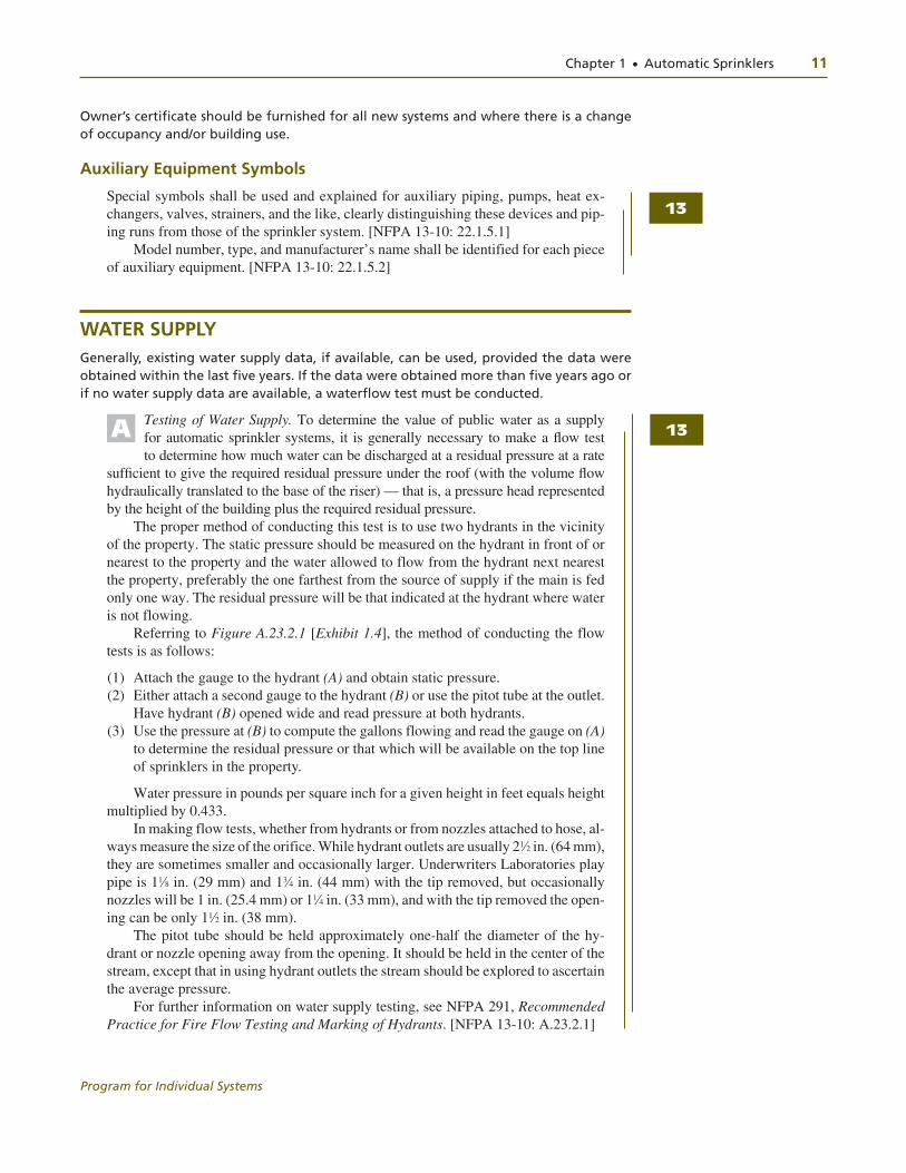
Owner’s certificate should be furnished for all new systems and where there is a change of occupancy and/or building use.
Auxiliary Equipment Symbols
Special symbols shall be used and explained for auxiliary piping, pumps, heat ex-changers, valves, strainers, and the like, clearly distinguishing these devices and pip-ing runs from those of the sprinkler system. [NFPA 13-10: 22.1.5.1]
Model number, type, and manufacturer’s name shall be identified for each piece of auxiliary equipment. [NFPA 13-10: 22.1.5.2]
WATER SUPPLYGenerally, existing water supply data, if available, can be used, provided the data were obtained within the last five years. If the data were obtained more than five years ago or if no water supply data are available, a waterflow test must be conducted.
Testing of Water Supply. To determine the value of public water as a supply for automatic sprinkler systems, it is generally necessary to make a fl ow test to determine how much water can be discharged at a residual pressure at a rate
suffi cient to give the required residual pressure under the roof (with the volume fl ow hydraulically translated to the base of the riser) — that is, a pressure head represented by the height of the building plus the required residual pressure.
The proper method of conducting this test is to use two hydrants in the vicinity of the property. The static pressure should be measured on the hydrant in front of or nearest to the property and the water allowed to flow from the hydrant next nearest the property, preferably the one farthest from the source of supply if the main is fed only one way. The residual pressure will be that indicated at the hydrant where water is not flowing.
Referring to Figure A.23.2.1 [Exhibit 1.4], the method of conducting the flow tests is as follows:
(1) Attach the gauge to the hydrant (A) and obtain static pressure. (2) Either attach a second gauge to the hydrant (B) or use the pitot tube at the outlet.
Have hydrant (B) opened wide and read pressure at both hydrants. (3) Use the pressure at (B) to compute the gallons flowing and read the gauge on (A)
to determine the residual pressure or that which will be available on the top line of sprinklers in the property.
Water pressure in pounds per square inch for a given height in feet equals height multiplied by 0.433.
In making flow tests, whether from hydrants or from nozzles attached to hose, al-ways measure the size of the orifice. While hydrant outlets are usually 21⁄2 in. (64 mm), they are sometimes smaller and occasionally larger. Underwriters Laboratories play pipe is 11⁄8 in. (29 mm) and 13⁄4 in. (44 mm) with the tip removed, but occasionally nozzles will be 1 in. (25.4 mm) or 11⁄4 in. (33 mm), and with the tip removed the open-ing can be only 11⁄2 in. (38 mm).
The pitot tube should be held approximately one-half the diameter of the hy-drant or nozzle opening away from the opening. It should be held in the center of the stream, except that in using hydrant outlets the stream should be explored to ascertain the average pressure.
For further information on water supply testing, see NFPA 291, Recommended Practice for Fire Flow Testing and Marking of Hydrants. [NFPA 13-10: A.23.2.1]
13
A 13

12 Chapter 1 ● Automatic Sprinklers
Program for Individual Systems
Capacity Data
The following information shall be included:
(1) Location and elevation of static and residual test gauge with relation to the riser reference point
(2) Flow location (3) Static pressure, psi (bar) (4) Residual pressure, psi (bar) (5) Flow, gpm (L/min) (6) Date (7) Time (8) Name of person who conducted the test or supplied the information (9) Other sources of water supply, with pressure or elevation [NFPA 13-10: 22.2.1]
Where a water fl ow test is used for the purposes of system design, the test shall be conducted no more than 12 months prior to working plan submittal. [NFPA 13-10: 22.2.1.1]
Treatment Data
The following information shall be included when water supply treatment is pro-vided in accordance with NFPA 13-10: 23.1.5:
(1) Type of condition that requires treatment (2) Type of treatment needed to address the problem (3) Details of treatment plan [NFPA 13-10: 22.2.2]
HYDRAULIC CALCULATION FORMSHydraulic calculation forms provide written, mathematical verification of the system’s pipe diameters and demonstrate that the attached water supply meets or exceeds the required flow and pressure of the fire protection system. The hydraulic calculations must be submitted any time the plans are submitted, because the plans cannot be reviewed completely without a review of the hydraulic characteristics of the system.
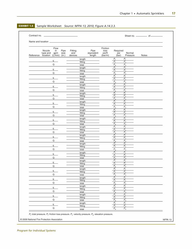
Hydraulic calculations shall be prepared on form sheets that include a summary sheet, detailed worksheets, and a graph sheet. [See copies of typical forms in Figure A.22.3.2(a), Figure A.22.3.3, and Figure A.22.3.4.][Exhibits 1.5, 1.6, 1.7], [NFPA 13-10: 22.3.1]
EXHIBIT 1.4 Method of Conducting Flow Tests
Gauge attachedto hydrant toshow static andresidual pressures
Gauge attached tohydrant or pitot tubeto register flowingpressure
Pitot tube
Public main
Source: NFPA 13, 2010, Figure A.15.2.1.
13
13
13

Chapter 1 ● Automatic Sprinklers 13
Program for Individual Systems
EXSummary Sheet
The summary sheet shall contain the following information, where applicable:
(1) Date (2) Location (3) Name of owner and occupant (4) Building number or other identification (5) Description of hazard (for storage applications, the commodity classification,
storage height, and rack configuration shall be included) (6) Name and address of contractor or designer (7) Name of approving agency (8) System design requirements, as follows:
(a) Design area of water application, ft2 (m2) (b) Minimum rate of water application (density), gpm/ft2 (mm/min). Where
sprinklers are listed with minimum water application in gpm (L/min) or pressure in psi (bar), the minimum rate of water application shall be indi-cated in gpm (L/min) or pressure, psi (bar).
(c) Area per sprinkler, ft2 (m2)
EXHIBIT 1.5 Sample Filled-Out Summary Sheet
Contract No.
Date
for
Design data:
Occupancy classification
Name of contractor
Name of designer
Address
Authority having jurisdiction
Density gpm/ft2
Area of application ft2
Coverage per sprinkler ft2
Special sprinklers
No. of sprinklers calculated
In-rack demand
Hose streams
Total water required gpmincluding hose streams
Hydraulic Calculations
ABC Company, employee garage
7499 Franklin Road
Charleston, SC
4001
1 – 7 – 08
ORD. GR. 10.15
1500
130
12
250 gpm
510.4
Source: NFPA 13, 2010, Figure A.14.3.2(a).
13

14 Chapter 1 ● Automatic Sprinklers
Program for Individual Systems
EXHIBIT 1.5 Continued
(9) Total water requirements as calculated, including allowance for inside hose, outside hydrants, and water curtain and exposure sprinklers
(10) Allowance for in-rack sprinklers, gpm (L/min) (11) Limitations (dimension, flow, and pressure) on extended coverage or other listed
special sprinklers [NFPA 13-10: 22.3.2]
1¹⁄₂ in
.
1¹⁄₂ in
.
1¹⁄₂ in
.
2 in. 2¹�₂ in. 2¹�₂ in. 2¹�₂ in. 2¹�₂ in. 2¹�₂ in. 2¹�₂ in. 3 in. 3 in. 3 in. 3 in. 3 in. 3 in. 3 in. 3 in. 3 in. 3 in.
4 5 6
3 in. riser
City
wat
er
mai
n
93 in.
#4
#3
#2
#1
Sprinkler #
#3#2#11f
t 0 in
.¥ 1
¹⁄₂
in. r
iser
nip
ple
130
ft0
in.
10 ft bays at 20 ft 0 in. = 200 ft 0 in.
Not
e: U
nder
grou
nd to
be
copp
er,
lined
cas
t iro
n, c
emen
t-as
best
os,
or fi
berg
lass
Calculated area — 1500 ft2
Spacing 13 ft ¥ 10 ft = 130 ft2
1500130
= 11.54 — Calculate 12 sprinklers
Use four sprinklers/line1.2 ÷1500 = 3.58
45 ft 0 in.
Group I — 1500 ft2
Density 0.15 gpm/ft2from Figure 11.2.3.1.1
13
8
16ft
0in
.
Elevation View
Reference step
260.4 gpm
See calculationsin Figure A.22.3.2(c) Alarm
valve
Indicating gate valve
3 in.
260.4 gpm
1¹⁄₂ in
.B
ranc
h lin
e
Bra
nch
line
Bra
nch
line
3 in.2¹�₂ in.2¹�₂ in.
1¹⁄₂ in
.
1¹⁄₂ in
.
1¹⁄₂ in
.1¹
⁄₄ in
.
1¹⁄₄ in
.
1¹⁄₄ in
.1
in.
1 in
.
1 in
.
1¹⁄₂ in
.
1¹⁄₂ in
.
13

Chapter 1 ● Automatic Sprinklers 15
Program for Individual Systems
Worksheet
Detailed worksheets or computer printout sheets shall contain the following informa-tion:
(1) Sheet number (2) Sprinkler description and discharge constant (K) (3) Hydraulic reference points
13
EXHIBIT 1.5 Continued
Contract Name Sheet Of
Ref
. Ste
p
NotesNormal Pressure
Pressure Summary
FrictionLosspsi
Foot
Equiv.Pipe
Length
Pipe Fittings
and Devices
Pipe Size
Flow in
gpm
Nozzle Ident. and
LocationSte
p N
o.
q
Q
q
Q
q
Q
q
q
Q
q
Q
q
Q
q
Q
q
Q
q
Q
q
Q
L
F
TL
F
TL
F
TL
F
TL
F
TL
F
TL
F
TL
F
T
LF
T
L
F
T
LF
T
Pt
Pe
Pf
Pt
Pe
Pt
Pt
Pe
Pt
Pt
Pt
Pt
Pt
Pt
Pt
Pt
Pt
Pv
Pt
Pt
Pt
Pt
Pv
Pt
Pt
Pt
Pt
Pt
Pn
2 3GROUP I 1500 ft2
1
2
3
4
5
6
7
8
9THROUGH
UNDER-GROUND
TOCITY MAIN
CM TOFIS
BL-3CM
BL-2CMTO
BL-3
CM TO
BL-2
DN RN
BL-1
19.5
20.7
40.2
21.9
62.1
23.1
85.2
86.3
171.5
88.1
259.6
259.6
259.63
3
2
11/4
1
13.0
13.013.0
13.013.0
13.020.52T-1616.0
36.510.0
10.010.0
10.070.0
70.0119.0E5
AV15
GV1E5GV1T15 77.6
27.650.0140.0
0.061TYPE'M'C=1500.081
0.231
0.107
0.07
0.236
0.131
0.125
0.124
C=120 12.1
1.613.7
1.615.3
1.717.0
8.626.0
0.726.7
1.127.8
16.244.0
6.511.2
61.7
4.766.4
D = 0.15 gpm/ft2
K = 5.6
Q = 130 x 0.15 = 19.5
q = 5.6
15.3q = 5.6
17q = 5.6
K = 85.226
K = 16.71
26.7q = 16.71
27.8q = 16.7
Pe = 15 x 0.433
F = F40 x 1.51 x FcFc = [2.981/3.068]4.87 = 0.869F = 21 x 1.51 x 0.869F = 27.6
9
8
6
5
4
1
2
3
4
÷
÷
÷
÷
÷
Q 85.2
11/2
11/2
21/2
21/2
21
0.4Pe = 1 x 0.433
P = (19.5/5.6)2 = 12.1 psi
13.7÷
Pt
Pe
Pe
Pe
Pe
Pe
Pe
Pe
Pe
Pf
Pf
Pf
Pf
Pf
Pf
Pf
Pf
Pf
Pf
Pv
Pv
Pv
Pv
Pv
Pv
Pn
Pn
Pn
Pn
Pn
Pn
Pn
Pn
Pn
Pn
Pv
Pv
Pv

16 Chapter 1 ● Automatic Sprinklers
Program for Individual Systems
(4) Flow in gpm (L/min) (5) Pipe size (6) Pipe lengths, center-to-center of fittings (7) Equivalent pipe lengths for fittings and devices (8) Friction loss in psi/ft (bar/m) of pipe (9) Total friction loss between reference points (10) In-rack sprinkler demand balanced to ceiling demand (11) Elevation head in psi (bar) between reference points (12) Required pressure in psi (bar) at each reference point (13) Velocity pressure and normal pressure if included in calculations (14) Notes to indicate starting points or reference to other sheets or to clarify data
shown (15) Diagram to accompany gridded system calculations to indicate flow quantities
and directions for lines with sprinklers operating in the remote area (16) Combined K-factor calculations for sprinklers on drops, armovers, or sprigs
where calculations do not begin at the sprinkler [NFPA 13-10: 22.3.3]
Graph Sheet
A graphic representation of the complete hydraulic calculation shall be plotted on semi-exponential graph paper (Q1.85) and shall include the following:
(1) Water supply curve (2) Sprinkler system demand (3) Hose allowance (where applicable) (4) In-rack sprinkler demand (where applicable) [NFPA 13-10: 22.3.4]
EXHIBIT 1.5 Continued
100
90
80
70
60
50
40
30
95
85
75
65
55
45
35
20
10
05
15
25
Scale AScale BScale C
100 200 400
200 400 800
300 600
1200
400 800
1600
500 1000 2000
600 1200 2400
700 1400 2800
800 1600 3200
Waterflow (gpm)
Pre
ssur
e (p
si)
260 gpm at 66.4 psi
1000 gpm at 60 psi
City water supply curve
System demand curve
Available for hose streams (must be minimum of 250 gpm fromTable 11.2.3.1.2)
Scale B
Static pressure due to elevation (Pe)
13
13
Chapter 1 ● Automatic Sprinklers 17
Program for Individual Systems
EXHIBIT 1.6 Sample Worksheet Source: NFPA 13, 2010, Figure A.14.3.3.
NFPA 13© 2009 National Fire Protection Association
q
Q
lengthfittingtotal
q
Q
q
Q
q
Q
q
Q
q
Q
q
Q
q
Q
q
Q
q
Q
q
Q
q
Q
q
Q
q
Q
q
Q
q
Q
q
Q
q
Q
Contract no. Sheet no. of
Name and location
Reference
Flow in
gpm (L/min)
Nozzle type andlocation
Pipe size(in.)
Fitting and
devices
Pipe equivalent
length
Frictionlosspsi/ft
(bar/m)
Required psi
(bar)Normal
Pressure Notes
lengthfittingtotallengthfittingtotallengthfittingtotallengthfittingtotallengthfittingtotallengthfittingtotallengthfittingtotallengthfittingtotallengthfittingtotallengthfittingtotal
lengthfittingtotallengthfittingtotallengthfittingtotallengthfittingtotallengthfittingtotallengthfittingtotallengthfitting
total
Pt: total pressure. Pf: friction loss pressure. Pv: velocity pressure. Pe: elevation pressure.
PtPf
Pe
PtPf
PePtPf
PePtPf
PePtPfPePtPf
Pe
PtPfPe
PtPfPe
Pt
PfPePtPf
PePtPf
Pe
Pt
PfPePt
PfPePtPfPe
PtPf
PePtPfPe
PtPfPe
PtPf
Pe
PtPv
PnPtPvPn
PtPvPn
PtPv
PnPtPv
PnPtPv
Pn
PtPvPn
PtPv
PnPtPvPn
PtPv
PnPtPv
Pn
PtPvPn
PtPvPn
PtPvPn
PtPv
Pn
PtPv
Pn
PtPvPn
PtPvPn

18 Chapter 1 ● Automatic Sprinklers
Program for Individual Systems
APPROVAL AND ACCEPTANCEInspections and Action Items
In addition to acceptance testing, approval and acceptance involves a number of inspec-tions or action items that must be documented on the contractor’s material and test cer-tificate (Exhibit 1.8) or other project closeout documentation These items are as follows:
● Installation of spare sprinklers ● Verification of pipe and fitting types ● Verification of test blank removal (if applicable) ● Welding certification (if applicable) ● Hydraulic data nameplate installation ● Field verification of as-built drawings ● Verification of approved equipment and components ● Verification of training of maintenance personnel ● Project closeout submittals, such as system component maintenance instructions,
general system care, maintenance instructions, and copy of NFPA 25, Standard for the Inspection, Testing, and Maintenance of Water-Based Fire Protection Systems
● Valve identification (installation of valve signs)
Although these items can be verified and documented on the Contractor’s Material and Test Certificate, training of operations personnel and submission of as-built plans and operation and maintenance manuals should be completed as discussed in Chapter 1.
EXHIBIT 1.7 Sample Graph Sheet
100 (378.5)
200 (757)
300 (1136)
400 (1514)
500 (1893)
600 (2271)
700 (2650)
800 (3028)
900 (3407)
1000 (3785)
Q1.85 Flow, gpm (L/min) (Multiply this scale by_______.)
Pre
ssur
e, p
si (
bar)
0
10 (0.69)
20 (1.4)
30 (2.1)
40 (2.8)
50 (3.5)
60 (4.1)
70 (4.8)
80 (5.5)
90 (6.2)
100 (6.9)
110(7.6)
120 (8.3)
Source: NFPA 13, 2010, Figure A.14.3.4.
Chapter 1 ● Automatic Sprinklers 19
Program for Individual Systems
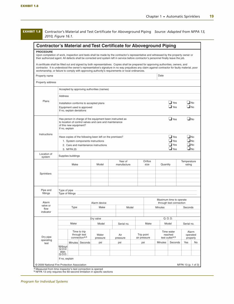
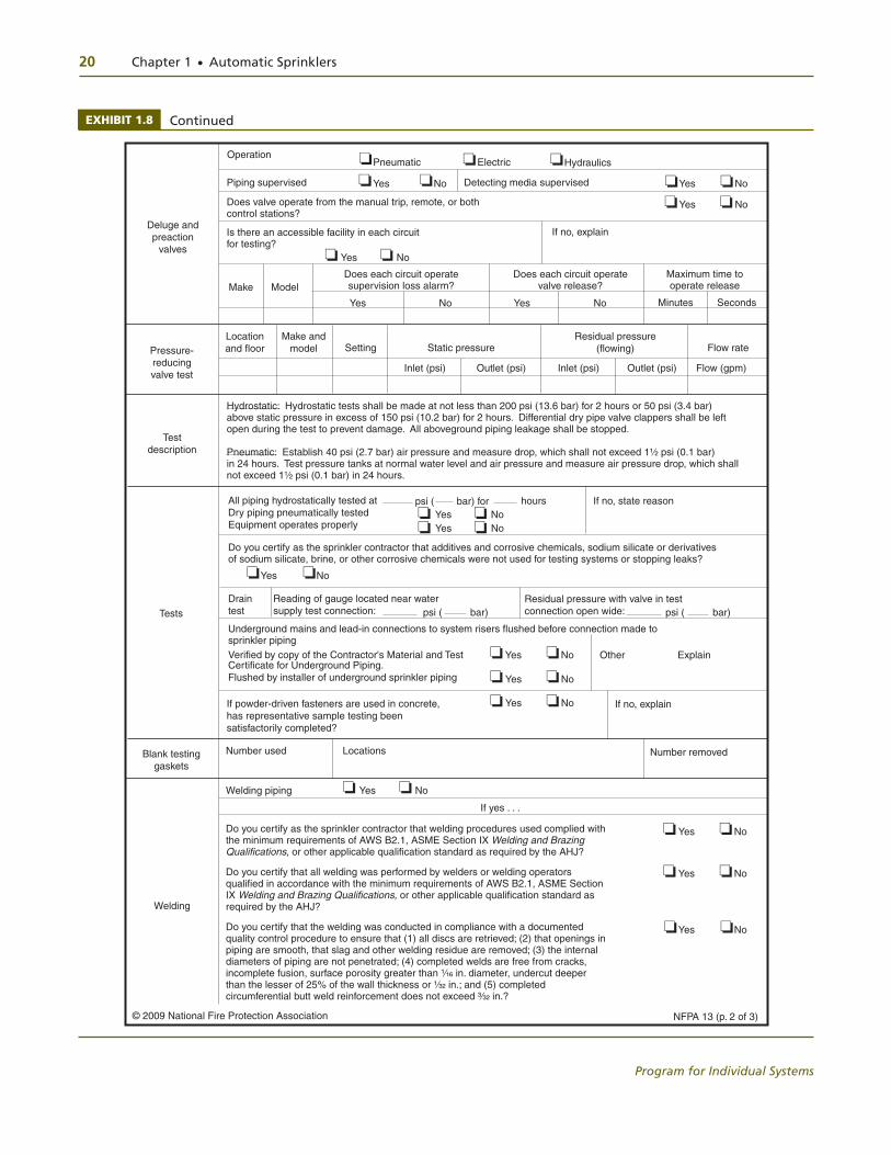
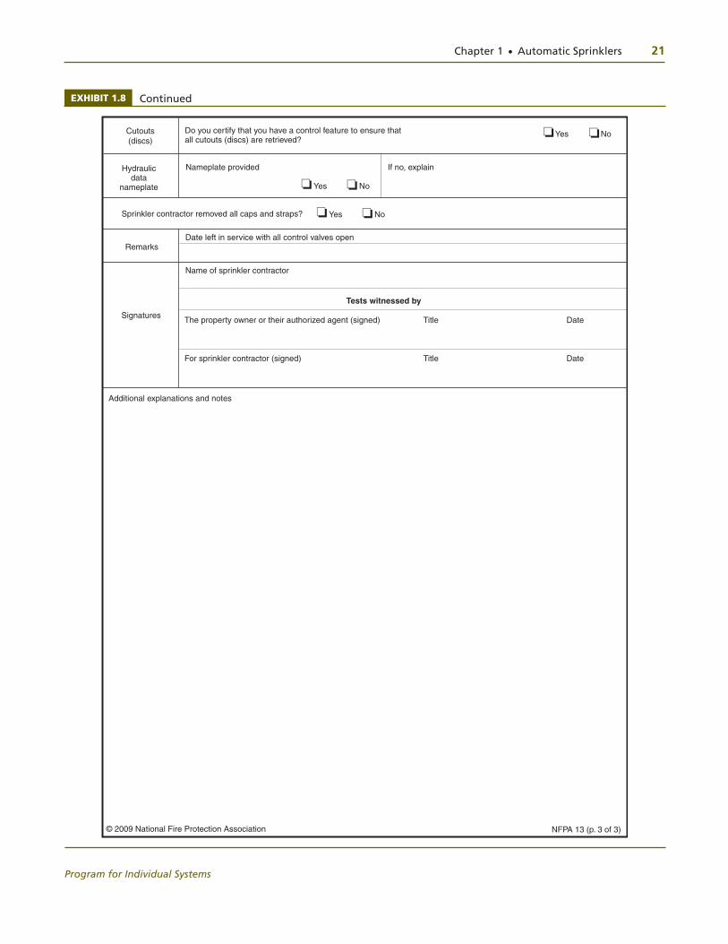
EXHIBIT 1.8 Contractor’s Material and Test Certifi cate for Aboveground Piping Source: Adapted from NFPA 13, 2010, Figure 16.1.
NFPA 13 (p. 1 of 3)
Contractor’s Material and Test Certificate for Aboveground Piping
a Measured from time inspector’s test connection is openedb NFPA 13 only requires the 60-second limitation in specific sections
PROCEDUREUpon completion of work, inspection and tests shall be made by the contractor’s representative and witnessed by the property owner or their authorized agent. All defects shall be corrected and system left in service before contractor’s personnel finally leave the job.
A certificate shall be filled out and signed by both representatives. Copies shall be prepared for approving authorities, owners, and contractor. It is understood the owner’s representative’s signature in no way prejudices any claim against contractor for faulty material, poor workmanship, or failure to comply with approving authority’s requirements or local ordinances.
Property address
Date
Accepted by approving authorities (names)
Address
Installation conforms to accepted plans
Equipment used is approvedIf no, explain deviations
Yes No
Yes No
Has person in charge of fire equipment been instructed asto location of control valves and care and maintenanceof this new equipment?If no, explain
Yes No
Have copies of the following been left on the premises?
1. System components instructions
2. Care and maintenance instructions
3. NFPA 25
Yes No
Yes No
Yes No
Yes No
Location of system Supplies buildings
Make ModelYear of
manufactureOrifice
size QuantityTemperature
rating
Sprinklers
Pipe andfittings
Alarmvalve or
flow indicator
Maximum time to operatethrough test connection
Make ModelType Minutes Seconds
Dry pipeoperating
test
Q. O. D.
Make Serial no. Make Model Serial no.
Time to tripthrough test
connectiona,bWater
pressureAir
pressureTrip point
air pressure
Time waterreached
test outleta,b
Alarmoperated properly
Minutes Seconds psi psi psi Minutes Seconds Yes No
Without Q.O.D.With
Q.O.D.
If no, explain
Type of pipeType of fittings
Alarm device
Model
Dry valve
Property name
Instructions
Plans
© 2009 National Fire Protection Association
❏❏❏❏
❏❏
❏❏❏❏❏❏❏❏
EXHIBIT 1.8
20 Chapter 1 ● Automatic Sprinklers
Program for Individual Systems
EXHIBIT 1.8 Continued
NFPA 13 (p. 2 of 3)
Deluge and preaction
valves
OperationPneumatic Electric Hydraulics
Piping supervised Yes No Detecting media supervised Yes No
Does valve operate from the manual trip, remote, or bothcontrol stations?
Yes No
Is there an accessible facility in each circuitfor testing?
If no, explain
Yes No
Make ModelDoes each circuit operatesupervision loss alarm?
Does each circuit operate valve release?
Maximum time to operate release
Yes No Yes No Minutes Seconds
Test description
Hydrostatic: Hydrostatic tests shall be made at not less than 200 psi (13.6 bar) for 2 hours or 50 psi (3.4 bar)above static pressure in excess of 150 psi (10.2 bar) for 2 hours. Differential dry pipe valve clappers shall be leftopen during the test to prevent damage. All aboveground piping leakage shall be stopped.
Pneumatic: Establish 40 psi (2.7 bar) air pressure and measure drop, which shall not exceed 1¹⁄₂ psi (0.1 bar)in 24 hours. Test pressure tanks at normal water level and air pressure and measure air pressure drop, which shallnot exceed 1¹⁄₂ psi (0.1 bar) in 24 hours.
Tests
All piping hydrostatically tested atDry piping pneumatically testedEquipment operates properly
psi ( bar) for hours If no, state reason
Do you certify as the sprinkler contractor that additives and corrosive chemicals, sodium silicate or derivatives of sodium silicate, brine, or other corrosive chemicals were not used for testing systems or stopping leaks?
Drain test
Reading of gauge located near watersupply test connection:
Yes No
psi ( bar)Residual pressure with valve in testconnection open wide:
Underground mains and lead-in connections to system risers flushed before connection made to sprinkler pipingVerified by copy of the Contractor's Material and Test Certificate for Underground Piping. Flushed by installer of underground sprinkler piping
Yes No
Yes No
Other Explain
Blank testing gaskets
Number used Locations Number removed
Welding
Do you certify as the sprinkler contractor that welding procedures used complied with the minimum requirements of AWS B2.1, ASME Section IX Welding and Brazing Qualifications, or other applicable qualification standard as required by the AHJ?
Do you certify that all welding was performed by welders or welding operators qualified in accordance with the minimum requirements of AWS B2.1, ASME Section IX Welding and Brazing Qualifications, or other applicable qualification standard as required by the AHJ?
Do you certify that the welding was conducted in compliance with a documented quality control procedure to ensure that (1) all discs are retrieved; (2) that openings in piping are smooth, that slag and other welding residue are removed; (3) the internal diameters of piping are not penetrated; (4) completed welds are free from cracks, incomplete fusion, surface porosity greater than ¹⁄₁₆ in. diameter, undercut deeper than the lesser of 25% of the wall thickness or ¹⁄₃₂ in.; and (5) completed circumferential butt weld reinforcement does not exceed ³⁄₃₂ in.?
Welding piping Yes No
If yes . . .
Yes No
Yes No
Yes No
Pressure- reducing valve test
Make and model Setting
Location and floor Static pressure
Residual pressure(flowing) Flow rate
Inlet (psi) Outlet (psi) Inlet (psi) Outlet (psi)
If powder-driven fasteners are used in concrete, has representative sample testing been satisfactorily completed?
If no, explainYes No
Flow (gpm)
psi ( bar)
Yes NoYes No
© 2009 National Fire Protection Association
❏
❏ ❏ ❏
❏ ❏ ❏❏ ❏
❏ ❏
❏❏❏❏
❏❏
❏❏
❏❏
❏❏
❏❏
❏❏
❏❏
❏❏
Chapter 1 ● Automatic Sprinklers 21
Program for Individual Systems
EXHIBIT 1.8 Continued
NFPA 13 (p. 3 of 3)
Cutouts (discs)
Do you certify that you have a control feature to ensure thatall cutouts (discs) are retrieved?
Yes No
Nameplate providedHydraulic data
nameplate Yes No
If no, explain
Remarks
Sprinkler contractor removed all caps and straps?
Date left in service with all control valves open
Signatures
Name of sprinkler contractor
Tests witnessed by
The property owner or their authorized agent (signed) Title Date
For sprinkler contractor (signed) Title Date
Additional explanations and notes
© 2009 National Fire Protection Association
❏ ❏
❏ ❏
Yes No❏ ❏
22 Chapter 1 ● Automatic Sprinklers
Program for Individual Systems
Acceptance Testing Activities
Acceptance testing involves a number of activities that must be performed, witnessed, and documented. These activities are as follows:
● Functional test of the system alarm device ● Trip and water transit time for dry-pipe systems ● Trip test for deluge/preaction systems ● Pressure-reducing valve test (if present) ● Hydrostatic test ● Main drain test
The completion of these tests can be documented on the contractor’s material and test certificate (Exhibit 1.8).
Approval Requirements
As defined by NFPA, approved means acceptable to the authority having jurisdiction (AHJ). During acceptance testing, it is customary to schedule the tests to allow the AHJ to witness the tests and sign the contractor’s material and test certificate. By witnessing the acceptance tests, the AHJ can verify that the system has been designed and installed in accordance with the plans, specifications, and all applicable codes and standards and functions to the satisfaction of the AHJ.
In addition to the preceding requirements, the project specifications may also require documentation in the form of a punch list for the following specialties:
● Installation of sprinkler and wall escutcheons ● Installation of sprinkler guards (where required) ● Pipe identification (where required) ● Installation of sleeves including appropriate packing material
The sprinkler checklist in Appendix D can be used for project closeout.
Contractor’s Responsibilities
By code, the contractor is responsible for scheduling the test and coordinating this sched-ule with all of the AHJs. The contractor will perform the test, complete the test reports, and have the AHJ sign the test report if satisfactory. If the system test fails, the contractor is usually responsible for any needed repairs or corrective action and subsequent retest.
The installing contractor shall do the following:
(1) Notify the authority having jurisdiction and the property owner or the property owner’s authorized representative of the time and date testing will be performed
(2) Perform all required acceptance tests [see NFPA 13-10: 24.2] (3) Complete and sign the appropriate contractor’s material and test certificate(s)
[see NFPA 13-10: Figure 24.1] [Exhibit 1.8] (4) Remove all caps and straps prior to placing the sprinkler system in service
[NFPA 13-10: 24.1]
Hydrostatic Tests
Testing PressureA hydrostatic test is a pressure test to reveal the presence of leaks in the piping system. For fire protection systems, the piping is pressurized to 200 psi (13.8 bar) for a period of 2 hours. During this time period, the system piping is inspected for leaks. Leaks in the pip-ing system are revealed either by observation of water droplets or by a reduction in test
13

Chapter 1 ● Automatic Sprinklers 23
Program for Individual Systems
pressure. Any leaks or reduction in test pressure necessitates a repair of the pipe joint in-volved and a retest to verify that the leak has been repaired. In cases where high pressure exists, the standard requires that the test pressure be 50 psi (3.5 bar) in excess of the nor-mal system pressure if the resultant test pressure will be greater than 200 psi (13.8 bar).
In the case of underground piping, a certain amount of leakage is allowed due to the type of valves and fittings permitted by the design standard. During the hydrostatic test of underground piping, a slight pressure loss should be anticipated. The system should be pressurized such that this slight pressure loss does not permit the test pressure to drop below the specified 200 psi (13.8 bar). Following the 2-hour test period, the pressure loss should be simulated by opening a small drain valve installed for the test and draining the water into a calibrated container. The water volume should be measured and compared to the values permitted by NFPA 13. If the amount of water drained from the system is less than permitted, the test can be considered to be acceptable.
Unless permitted by 24.2.1.2 through 24.2.1.8, all piping and attached appurtenances subjected to system working pressure shall be hydrostatically tested at 200 psi (13.8 bar) and shall maintain that pressure without loss for 2 hours. [NFPA 13-10: 24.2.1.1]
Portions of systems normally subjected to system working pressures in excess of 150 psi (10.4 bar) shall be tested as described in 24.2.1.1, at a pressure of 50 psi (3.5 bar) in excess of system working pressure. [NFPA 13-10: 24.2.1.2]
Where cold weather will not permit testing with water, an interim air test shall be permitted to be conducted as described in 24.2.2. This provision shall not remove or replace the requirement for conducting the hydrostatic test as described in 24.2.1.1. [NFPA 13-10: 24.2.1.3]
Modifications affecting 20 or fewer sprinklers shall not require testing in excess of system working pressure. [NFPA 13-10: 24.2.1.4]
Where addition or modification is made to an existing system affecting more than 20 sprinklers, the new portion shall be isolated and tested at not less than 200 psi (13.8 bar) for 2 hours. [NFPA 13-10: 24.2.1.5]
Modifications that cannot be isolated, such as relocated drops, shall not require testing in excess of system working pressure. [NFPA 13-10: 24.2.1.6]
While there are multiple methods for conducting the hydrostatic test, basic procedures for conducting these are as follows.
Hydrostatic Test Procedure for Water-Based Fire Protection Systems
Description ● General acceptance test of water-based fire protection systems ● Accomplished by visual inspection and hydrostatic pressure
Objective ● To ensure piping integrity and absence of leaks
Conditions/Assumptions ● Piping system, including all valves, drains, and accessories, are installed ● Underground supply has been installed, flushed, tested, and activated
Specifications ● Appropriate NFPA installation standard • Underwriters Laboratories (UL) Fire Protection Equipment Directory • Factory Mutual (FM) Approval Guide • Local/state building codes (as applicable) ● Approved fire protection shop drawings ● Project specifications
13
24 Chapter 1 ● Automatic Sprinklers
Program for Individual Systems
Test Equipment ● Pressure pump ● Calibrated test gauges ● Fittings, hose, plugs, valves, and tools, as required
Test Parameters ● This procedure delineates the method for hydrostatic testing of a water-based
fire protection system.
– The system installation shall be complete and verified by visual inspection. – All openings shall be plugged, and valves shall be closed. – Test blanks shall be installed, as necessary, to isolate the system being tested. – Whenever a test blank is used, it shall be of the self-indicating type. – Test blanks shall have red painted lugs protruding beyond the flange in
such a way as to clearly indicate their presence. – The installer shall have all test blanks numbered to assure their removal
after the test is completed. – A written log should be used to monitor the use of test blanks.
● Water used for testing the system should be taken from the same source that will supply the system wherever possible.
● A test pump will be used to achieve the required test pressure.
– A calibrated test gauge shall be used. – The calibration tolerance shall be +/-5%. – Test gauges supplied by the owner or commissioning agent may be used. – The dial of the test gauge shall be graduated over a range of at least 1.5
times the intended test pressure, but not more than 4 times that pressure.
Test Procedure ● Inspect the system to verify that openings are plugged and valves are closed. ● Connect the test pump to a convenient location in the system. ● Connect the water source to the test pump. ● Open the main control valve to fill the system. (If the water service is not installed
or has not been flushed, fill the system through the test pump water source.) ● Fill the system slowly to avoid entrapment of air. ● Open a valve (such as the inspector’s test connection or a temporary valve) to
vent any trapped air. ● Close the valve when water flows continuously through it. ● When the system pressure equals that of the water source, close the supply
valve and inspect the entire system for leaks.
– Leaks may result from flanges not bolted properly, plugs not properly in-stalled, cracked or improperly tightened fittings, etc.
– If leaks are found, open the 2-in. main drain connection or other low-point drain connection and allow the system to drain. Repair any leaks found and repeat this procedure.
– If no leaks are detected, begin to increase pressure with the test pump up to 200 psi or 50 psi in excess of the static pressure when static pressure exceeds 150 psi.
● Monitor the test gauge to determine that the system pressure is stable. If pres-sure drops, check for leaks in the system, for open valves, or for leaks in the test apparatus.
● Once it is determined that the test pressure has stabilized, disconnect the power to the test pump and notify the commissioning agent or authority hav-ing jurisdiction that the 2-hour test period has begun.
Chapter 1 ● Automatic Sprinklers 25
Program for Individual Systems
● Record the time of day and test pressure at this time. ● Hold the test pressure for 2 hours. ● After the test, open the drain valve to drain the system, or, if the system is to
be commissioned immediately, relieve the test pressure and leave the water in the system.
● Disconnect the test pump and plug the outlet or test port through which the system was tested.
Measurements ● Test pressure is to be maintained for 2 hours without any visible leaks.
Pass/Fail Criteria ● The system must hold the test pressure for 2 hours without loss of pressure. ● Absence of water leakage is verified by visual examination of the system.
Hydrostatic Test Procedure for Underground Fire Service Mains
Description ● General acceptance of underground fire service main ● System acceptance in sections or in entirety as authorized by authority having
jurisdiction ● Ensure city main valves are closed and locked before opening fire pump valves
Objective ● To ensure piping integrity and absence of leaks
Conditions/Assumptions ● Adequate water supply is available ● Isolation valves are open or closed as appropriate ● Thrust blocks (as required) are properly installed ● Pipe or pipe segments are properly installed
Specifications ● Appropriate NFPA installation standard ● Underwriters Laboratories (UL) Fire Protection Equipment Directory ● Factory Mutual (FM) Approval Guide ● Local/state building codes (as applicable) ● Approved fire protection shop drawings ● Project specifications
Test Equipment ● Pressure pump ● Calibrated gauges ● Flanges, connectors, hose, and tools required to connect to system ● Calibrated liquid container
Test Parameters ● This procedure describes the method used to flush and test underground sys-
tems in accordance with the project specification.
– The underground piping is flushed using the hydraulic method, consisting of flowing water through the underground piping in the same direction in which it would flow during a fire.
– The purpose of flushing is to remove obstructive material from the pipe. – Successful flushing is dependent on establishing sufficient velocity of flow
to remove the obstructing materials. – When the water supply cannot produce the stipulated flow rates, the maxi-
mum available must be used. Table 9.1.1 of NFPA 24 provides the required water flow for flushing piping.
26 Chapter 1 ● Automatic Sprinklers
Program for Individual Systems
– The owner’s representative shall be notified at least 24 hours prior to the start of flushing.
– The flushing may be accomplished by using the existing fire water supply system feeding the system being flushed.
– Water used for flushing shall be that contained in the existing fire water supply system feeding the system being flushed.
– After making the appropriate water supply connections, provisions are made for the disposal of the water issuing from the test outlets to avoid property damage.
– Water is allowed to flow 4 or 5 minutes or until water is clean.
● This procedure delineates the method for hydrostatic testing of the under-ground supply to fire protection systems.
● The test should be made before the joints are covered, if practical, so any leaks may be readily detected.
● Thrust blocks should be sufficiently hardened before testing is begun.
– Inspect the system to ensure that openings are plugged and valves are closed. – Connect the test pump to a convenient location in the system. – Connect the water source to the test pump. – Open the main control valve to fill the system (if water service is not com-
pleted, fill the system through test water source). – Fill the system slowly. – Vent the air from the system through a temporary valved connection or
other appropriate means. – Close the vent when water flows continuously through it. – Begin to increase pressure with the test pump up to 200 psi or 50 psi in
excess of the maximum static pressure when static pressure exceeds 150 psi. – Monitor the test gauge to determine that the system pressure is not escaping. – If pressure drops, check for leaks in the system, for open valves, or for leaks
on the test apparatus. – If the system holds the required test pressure, disconnect the power to the
pump and notify the commissioning agent or authority having jurisdiction designated to witness the test that the 2-hour test period has begun.
– Record the time of day and test pressure at this time.
● Measure the amount of leakage in the system at the specified test pressure by pumping from a calibrated container.
– For new pipe, the amount of leakage at the joints should not exceed 2 quarts per hour per 100 gaskets or joints, irrespective of pipe diameter.
– The amount of allowable leakage may be increased by 1 fluid ounce per inch valve diameter per hour for each metal-seated valve isolating the test section. If dry barrel hydrants are tested with the main valve open, so the hydrants are under pressure, an additional 5 ounces per minute leakage is permitted for each hydrant.
– New pipe installed with rubber gasketed joints should, if the workmanship is satisfactory, have no leakage at the joints. Unsatisfactory amounts of leakage usually result from twisted, pinched, or cut gaskets. Some leakage might result from small amounts of grit or small imperfections in the sur-faces of the pipe joints.
● After the test, open the drain valve to drain system. ● Once the system is drained, disconnect test pump and plug opening through
which the system is tested.

Chapter 1 ● Automatic Sprinklers 27
Program for Individual Systems
Measurements ● System pressure ● Quantity of liquid required from calibrated container to maintain the test
pressure
Pass/Fail Requirements ● Test pressure is maintained without significant decrease. ● Quantity of water required to maintain system does not exceed allowable. ● No visible leakage is observed.
Air Testing
It is important to note that an interim air test is permitted only where there is concern for freezing. When possible, a hydrostatic test using water must be completed.
Where cold weather will not permit testing with water, an interim air test shall be per-mitted to be conducted as described in NFPA 13-10: 24.2.2. This provision shall not remove or replace the requirement for conducting the hydrostatic test as described in NFPA 13-10: 24.2.1.1. [NFPA 13-10: 24.2.1.3]
A sample test procedure for an air test is as follows.
Pneumatic Test Procedure for Water-Based Fire Protection Systems
Description ● General acceptance test of water-based fire protection system. ● Accomplished by visual inspection and pneumatic pressure. ● This is an interim test during seasons when freezing may occur; hydrostatic
testing is required when weather permits.
Objective ● To ensure piping integrity and absence of leaks
Conditions/Assumptions ● Piping system, including all valves, drains, and accessories, is installed. ● Underground supply has been installed, flushed, tested, and activated. ● Available air supply is adequate to test the system.
Specifications ● Appropriate NFPA installation standard ● Underwriters Laboratories (UL) Fire Protection Equipment Directory ● Factory Mutual (FM) Approval Guide ● Local/state building codes (as applicable) ● Approved fire protection shop drawings ● Project specifications ● ASTM specifications
Test Equipment ● Supply air in excess of 50 psi or air compressor ● Calibrated test gauges ● Fittings, hose, plugs, valves, and tools, as required
Test Parameters ● This procedure delineates the method for pneumatic testing of a water-based
fire protection system.
– The system installation shall be complete and verified by visual inspection. – All openings shall be plugged, and valves shall be closed. – Test blanks shall be installed, as necessary, to isolate the system being tested.
13

28 Chapter 1 ● Automatic Sprinklers
Program for Individual Systems
– Whenever a test blank is used, it shall be of the self-indicating type. – Test blanks shall have red painted lugs protruding beyond the flange in
such a way as to clearly indicate their presence. – The installer shall have all test blanks numbered to assure their removal
after the test is completed. – A written log should be used to monitor the use of test blanks.
● The clapper of a differential type dry-pipe valve shall be held off its seat dur-ing any test in excess of 50 psi to prevent damaging the valve.
● A test pump will be used to achieve the required test pressure. ● A calibrated test gauge shall be used.
– The calibration tolerance shall be +/-5%. – Test gauges supplied by the owner or commissioning agent may be used. – The dial of the test gauge shall be graduated over a range of at least 1.5
times the intended test pressure, but not more than 4 times that pressure.
Test Procedure ● Inspect the system to verify that openings are plugged and valves are closed. ● Connect the air supply to a convenient location in the system. ● Fill the system slowly. ● When the system reaches 40 psi, close the supply valve and inspect the entire
system for leaks.
– Leaks may result from flanges not bolted properly, plugs not properly in-stalled, cracked or improperly tightened fittings, etc.
– If leaks are found, bleed off air pressure. Repair any leaks found and repeat the test.
– A soap solution or any acceptable indicating solution may be used on areas suspected to be leaking to determine the exact location of leaks.
● Monitor the test gauge to determine that the system pressure is stable. If pres-sure drops over 1.5 psi in 24 hours, check for leaks in the system, open valves, or leaks in the test apparatus.
● Once it has been determined that the test pressure has stabilized, shut off the air supply and notify the commissioning agent or authority having jurisdiction that the 24-hour test period has begun.
● Record the time of day and the pressure at this time. ● Hold the test pressure for 24 hours. ● After the test, open the drain valve to bleed air from the system. ● Once the air pressure is bled off, disconnect the air supply and plug the open-
ing through which the system was tested.
Measurements ● Test pressure is to be maintained for 24 hours without any visible leaks in the
system or loss of 1.5 psi during the 24-hour test period.
Pass/Fail Criteria ● The system must hold the test pressure for 24 hours without loss of more than 1.5 psi. ● Absence of leakage is verified by visual examination of the system.
Pressure Loss
Loss shall be determined by a drop in gauge pressure or visual leakage. [NFPA 13-10: 24.2.1.7]
The test pressure shall be read from a gauge located at the low elevation point of the system or portion being tested. The pressures in piping at higher elevations shall
13

Chapter 1 ● Automatic Sprinklers 29
Program for Individual Systems
be permitted to be less than 200 psi (13.8 bar) when accounting for elevation losses. Systems or portions of systems that can be isolated shall be permitted to be tested separately. [NFPA 13-10: 24.2.1.8]
Additives or Chemicals
Additives, corrosive chemicals such as sodium silicate, or derivatives of sodium sili-cate, brine, or similar acting chemicals shall not be used while hydrostatically testing systems or for stopping leaks. 24.2.1.9. [NFPA 13-10: 24.2.1.9]
Piping Testing
Piping between the exterior fi re department connection and the check valve in the fi re department inlet pipe shall be hydrostatically tested in the same manner as the balance of the system. After repair or replacement work affecting the fi re department connection, the piping between the exterior and the check valve in the fi re department inlet pipe shall be isolated and hydrostatically tested at 150 psi (10.3 bar). [NFPA 13-10: 24.2.1.10]
Deluge Systems Testing
When deluge systems are being hydrostatically tested, plugs shall be installed in fi t-tings and replaced with open sprinklers after the test is completed, or the operating elements of automatic sprinklers shall be removed after the test is completed. [NFPA 13-10: 24.2.1.12]
In order to test the pipe shown in Exhibit 1.9, the trench should be backfilled in such a way as to reveal the pipe joints for inspection for leaks when hydrotesting is taking place. Upon completion of the hydrostatic test, backfill and compaction of earth can be completed.
Hydrostatic tests should be made before the joints are covered, so that any leaks can be readily detected. Thrust blocks should be suffi ciently hardened
before hydrostatic testing is begun. If the joints are covered with backfi ll prior to testing, the contractor remains responsible for locating and correcting any leakage in excess of that permitted. [NFPA 13-10: A.10.10.2.2.4]
System Operational Tests
Commonly referred to as an alarm test, the system operational test is completed by opening the inspector’s test connection. The inspector’s test connection is a length of pipe usually installed on the portion of the system most remote from the water supply connection. This pipe terminates in a smooth-bore, corrosion-resistant outlet that is sized to simulate the flow of a single sprinkler. The purpose of this test is to approxi-mate the flow of a single sprinkler to verify that such a small flow of water will activate the water flow alarm.
The acceptance criterion, as stated earlier, is an alarm that must sound within 5 min-utes. The 5-minute criterion is acceptable only when the alarm is composed of a local alarm bell or water motor alarm gong. It is important to note that if the sprinkler sys-tem is connected to a fire alarm system, then the water flow alarm must sound within 90 seconds. Sprinkler systems are frequently connected to fire alarm systems by means of a pressure switch or vane-type flow switch. Both devices are equipped with a retard set-ting, which is intended to compensate for momentary pressure surges, thus preventing false alarms. The delay setting, however, should be adjusted to sound an alarm within the 90 seconds required by NFPA 72®, National Fire Alarm Code®.
13
13
13
13
13A

30 Chapter 1 ● Automatic Sprinklers
Program for Individual Systems
Waterfl ow detecting devices including the associated alarm circuits shall be fl ow tested through the inspector’s test connection and shall result in an audible alarm on the premises within 5 minutes after such fl ow begins and until such fl ow stops. [NFPA 13-10: 24.2.3.1]
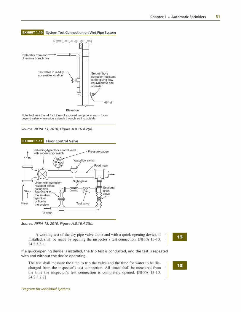
Exhibit 1.10 illustrates a system test connection on a wet pipe system, and Exhibit 1.11 illustrates the operation of a floor control valve.
Dry Pipe
Dry-pipe systems are used to protect unheated spaces. The system is pressurized with air to hold the dry-pipe valve closed. It is not desirable to fill the system piping with water in cold weather, since the water in the pipe may freeze. This section of NFPA 13 permits a trip test without filling the system so that operation of the dry-pipe valve may be dem-onstrated. To accomplish this test, the water supply control valve is opened only partially (a few turns of the valve handle). The system is tripped by releasing the air pressure in the system. Immediately upon dry-pipe valve actuation, the water supply control valve is closed, thus preventing water from entering the system.
When the acceptance test is being performed during freezing conditions, a partial fl ow trip test should be conducted at that time and the full fl ow trip
test specifi ed should be conducted as soon as conditions permit. [NFPA 13-10: A.24.2.3.2]
EXHIBIT 1.9 Bearing Thrust Block
Undisturbed soil b
SbBearing pressure
Sb
q
45∞
45∞
Sb
Sb
Ht
h
T = thrust force resulting from the change in direction of flow Sb = horizontal bearing strength of the soil h = block height
Ht = total depth to bottom of block
T
Source: NFPA 24, 2010, Figure A.10.8.2(c).
A
13
13
Chapter 1 ● Automatic Sprinklers 31
Program for Individual Systems
A working test of the dry pipe valve alone and with a quick-opening device, if installed, shall be made by opening the inspector’s test connection. [NFPA 13-10: 24.2.3.2.1]
If a quick-opening device is installed, the trip test is conducted, and the test is repeated with and without the device operating.
The test shall measure the time to trip the valve and the time for water to be dis-charged from the inspector’s test connection. All times shall be measured from the time the inspector’s test connection is completely opened. [NFPA 13-10: 24.2.3.2.2]
EXHIBIT 1.10 System Test Connection on Wet Pipe System
Preferably from endof remote branch line
Test valve in readilyaccessible location
45∞ ell
Smooth borecorrosion-resistantoutlet giving flowequivalent to onesprinkler
Elevation
Note: Not less than 4 ft (1.2 m) of exposed test pipe in warm roombeyond valve where pipe extends through wall to outside.
Source: NFPA 13, 2010, Figure A.8.16.4.2(a).
EXHIBIT 1.11 Floor Control Valve
300 150
1209060
Indicating-type floor control valvewith supervisory switch
Waterflow switch
Pressure gauge
Feed main
Sectional drain valve
To drain
Riser Test valve
Sight glassUnion with corrosion-resistant orificegiving flowequivalent tothe smallestsprinkler orifice inthe system
Source: NFPA 13, 2010, Figure A.8.16.4.2(b).
13
13
32 Chapter 1 ● Automatic Sprinklers
Program for Individual Systems
Dry systems calculated for water delivery in accordance with 7.2.3.6 shall be exempt from any specific delivery time requirement. [NFPA 13-10: 24.2.3.2.2.1]
The results shall be recorded using the contractor’s material and test certificate for aboveground piping [see Figure 24.]. [Exhibit 1.8] [NFPA 13-10: 24.2.3.2.3]
Deluge Systems
The automatic operation of a deluge or preaction valve shall be tested in ac-cordance with the manufacturer’s instructions. [NFPA 13-10: A.24.2.3.3.1]
The manual and remote control operation, where present, shall also be tested.[NFPA 13-10: 24.2.3.3.2]
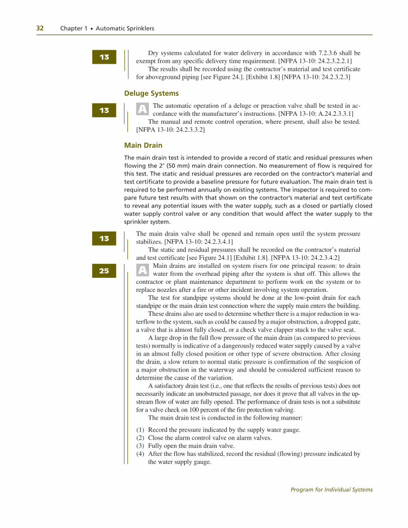
Main Drain
The main drain test is intended to provide a record of static and residual pressures when flowing the 2� (50 mm) main drain connection. No measurement of flow is required for this test. The static and residual pressures are recorded on the contractor’s material and test certificate to provide a baseline pressure for future evaluation. The main drain test is required to be performed annually on existing systems. The inspector is required to com-pare future test results with that shown on the contractor’s material and test certificate to reveal any potential issues with the water supply, such as a closed or partially closed water supply control valve or any condition that would affect the water supply to the sprinkler system.
The main drain valve shall be opened and remain open until the system pressure stabilizes. [NFPA 13-10: 24.2.3.4.1]
The static and residual pressures shall be recorded on the contractor’s material and test certificate [see Figure 24.1] [Exhibit 1.8]. [NFPA 13-10: 24.2.3.4.2]
Main drains are installed on system risers for one principal reason: to drain water from the overhead piping after the system is shut off. This allows the
contractor or plant maintenance department to perform work on the system or to replace nozzles after a fire or other incident involving system operation.
The test for standpipe systems should be done at the low-point drain for each standpipe or the main drain test connection where the supply main enters the building.
These drains also are used to determine whether there is a major reduction in wa-terflow to the system, such as could be caused by a major obstruction, a dropped gate, a valve that is almost fully closed, or a check valve clapper stuck to the valve seat.
A large drop in the full flow pressure of the main drain (as compared to previous tests) normally is indicative of a dangerously reduced water supply caused by a valve in an almost fully closed position or other type of severe obstruction. After closing the drain, a slow return to normal static pressure is confirmation of the suspicion of a major obstruction in the waterway and should be considered sufficient reason to determine the cause of the variation.
A satisfactory drain test (i.e., one that reflects the results of previous tests) does not necessarily indicate an unobstructed passage, nor does it prove that all valves in the up-stream flow of water are fully opened. The performance of drain tests is not a substitute for a valve check on 100 percent of the fire protection valving.
The main drain test is conducted in the following manner:
(1) Record the pressure indicated by the supply water gauge. (2) Close the alarm control valve on alarm valves. (3) Fully open the main drain valve. (4) After the flow has stabilized, record the residual (flowing) pressure indicated by
the water supply gauge.
13
13
13
A
A25

Chapter 1 ● Automatic Sprinklers 33
Program for Individual Systems
(5) Close the main drain valve slowly. (6) Record the time taken for the supply water pressure to return to the original
static (nonflowing) pressure. (7) Open the alarm control valve. [NFPA 25-11: A.13.2.5]
Operating Test
Hydrants and Control Valves
Each hydrant shall be fully opened and closed under system water pressure. [NFPA 24-10:10.10.2.4.1]
Dry barrel hydrants shall be checked for proper drainage. [NFPA 24-10:10.10.2.4.2]
All control valves shall be fully closed and opened under system water pressure to ensure proper operation. [NFPA 24-10:10.10.2.4.3]
Where fire pumps are available, the operating tests required by 10.10.2.4 shall be completed with the pumps running. [NFPA 24-10:10.10.2.4.4]
All control valves shall be fully closed and opened under system water pressure to ensure proper operation. [NFPA 13-10: 24.2.3.5]
Pressure-Reducing Valves
Pressure-reducing valves must be flow tested to verify the correct pressure setting. Failure to perform this test can result in system damage.
Each pressure-reducing valve shall be tested upon completion of installation to en-sure proper operation under fl ow and no-fl ow conditions. [NFPA 13-10: 24.2.4.1]
Testing shall verify that the device properly regulates outlet pressure at both maximum and normal inlet pressure conditions. [NFPA 13-10: 24.2.4.2]
The results of the flow test of each pressure-reducing valve shall be recorded on the contractor’s material and test certificate [see Figure 24.]). [Exhibit 1.8] [NFPA 13-10: 24.2.4.3]
The results shall include the static and residual inlet pressures, static and residual outlet pressures, and the flow rate. [NFPA 13-10: 24.2.4.4]
Backflow Prevention Devices
Backflow prevention devices are not fire protection devices and add nothing to the pro-tection features of a sprinkler system. Under the requirements of NFPA 13, these valves must be subject to a flow test to verify that they are operating correctly and the friction loss associated with these devices has been taken into consideration in the hydraulic de-sign. As part of the system commissioning, a backflow prevention test may be required by other regulations, such as environmental or health authority requirements.
The backfl ow prevention assembly shall be forward fl ow tested to ensure proper operation. [NFPA 13-10: 24.2.5.1]
The minimum flow rate shall be the system demand, including hose stream al-lowance where applicable. [NFPA 13-10: 24.2.5.2]
Exposure Systems
Operating tests shall be made of exposure protection systems upon completion of the installation, where such tests do not risk water damage to the building on which they are installed or to adjacent buildings. [NFPA 13-10: 24.2.6]
25
24
13
13
13
13
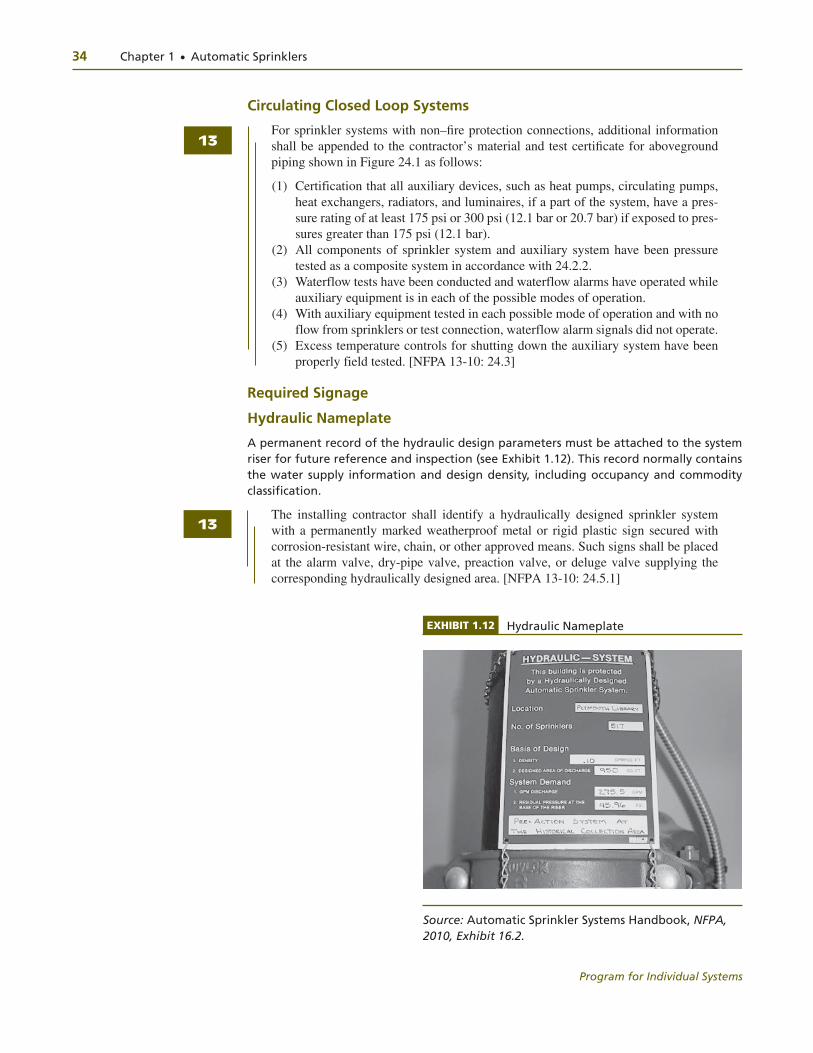
34 Chapter 1 ● Automatic Sprinklers
Program for Individual Systems
Circulating Closed Loop Systems
For sprinkler systems with non–fi re protection connections, additional information shall be appended to the contractor’s material and test certifi cate for aboveground piping shown in Figure 24.1 as follows:
(1) Certification that all auxiliary devices, such as heat pumps, circulating pumps, heat exchangers, radiators, and luminaires, if a part of the system, have a pres-sure rating of at least 175 psi or 300 psi (12.1 bar or 20.7 bar) if exposed to pres-sures greater than 175 psi (12.1 bar).
(2) All components of sprinkler system and auxiliary system have been pressure tested as a composite system in accordance with 24.2.2.
(3) Waterflow tests have been conducted and waterflow alarms have operated while auxiliary equipment is in each of the possible modes of operation.
(4) With auxiliary equipment tested in each possible mode of operation and with no flow from sprinklers or test connection, waterflow alarm signals did not operate.
(5) Excess temperature controls for shutting down the auxiliary system have been properly field tested. [NFPA 13-10: 24.3]
Required Signage
Hydraulic Nameplate
A permanent record of the hydraulic design parameters must be attached to the system riser for future reference and inspection (see Exhibit 1.12). This record normally contains the water supply information and design density, including occupancy and commodity classification.
The installing contractor shall identify a hydraulically designed sprinkler system with a permanently marked weatherproof metal or rigid plastic sign secured with corrosion-resistant wire, chain, or other approved means. Such signs shall be placed at the alarm valve, dry-pipe valve, preaction valve, or deluge valve supplying the corresponding hydraulically designed area. [NFPA 13-10: 24.5.1]
EXHIBIT 1.12 Hydraulic Nameplate
Source: Automatic Sprinkler Systems Handbook, NFPA, 2010, Exhibit 16.2.
13
13

Chapter 1 ● Automatic Sprinklers 35
Program for Individual Systems
As-built drawings often become lost or misplaced over time. By keeping a permanent record of the design parameters attached to the system riser, as required by NFPA 13-10: 24.5.1, it is much easier and less costly to perform any future modifications or work on the system. The information contained on such a nameplate is also of vital importance in assessing the ability of the system to control fires as the building’s occupancy changes or the water supply’s strength deteriorates.
The sign shall include the following information:
(1) Location of the design area or areas (2) Discharge densities over the design area or areas (3) Required flow and residual pressure demand at the base of the riser (4) Occupancy classification or commodity classification and maximum permitted
storage height and configuration (5) Hose stream allowance included in addition to the sprinkler demand (6) The name of the installing contractor [NFPA 13-10: 24.5.2]
A sample nameplate is provided in Exhibit 1.13.
SUMMARYThe minimum requirements for commissioning a sprinkler system involve a number of tests, including a hydrostatic pressure test to verify piping integrity, a main drain test to establish baseline water supply pressures (static and residual), and a water flow test to
EXHIBIT 1.13 Sample Nameplate
Hose stream allowance of . . . . . . . . . . . . . . . . . . . gpm (L/min)
is included in the above.
Occupancy classification . . . . . . . . . . . . . . . . . . . . . . . . . . . . . . . .
Commodity classification . . . . . . . . . . . . . . . . . . . . . . . . . . . . . . . .
Maximum storage height . . . . . . . . . . . . . . . . . . . . . . . . . . . . . . . .
This system as shown on . . . . . . . . . . . . . . . . . . . . . . . company
print no . . . . . . . . . . . . . . . . . . . . . . . . . . .
for . . . . . . . . . . . . . . . . . . . . . . . . . . . . . . . . . . . . . . . . . . . . . . . . . . . .
at . . . . . . . . . . . . . . . . . . . . . . . . . . . . . . . . contract no . . . . . . . . .
is designed to discharge at a rate of . . . . . . . . . . . . . . . gpm/ft2
(L/min/m2) of floor area over a maximum area of . . . . . . . . . .
ft2 (m2) when supplied with water at a rate of . . . . . . . . . . . . . .
gpm (L/min) at . . . . . . . . . . . . psi (bar) at the base of the riser.
dated . . . . . . . . . . . . . .
Source: NFPA 13, 2010, Figure A.16.5.
13

36 Chapter 1 ● Automatic Sprinklers
Program for Individual Systems
confirm operation of system alarms. These tests are usually documented on the contrac-tor’s material and test certificate. This test certificate also requires verification of other checks of the system, such as as-built drawings and care and maintenance instructions.
In addition to the information required by the test certificate, NFPA 13 requires other components to be installed, such as pipe sleeves and valve signs. The installation and adequacy of these components or other equipment and components can be verified by a checklist. Also, the training and documentation recommendations in Part One of NFPA 3 should be followed to properly document the commissioning activities for the system.