automatic room temperature controller abd....
TRANSCRIPT

AUTOMATIC ROOM TEMPERATURE CONTROLLER
ABD. HALIM BIN ZAKARIA
This report is submitted in partial fulfillment of the requirements for the award
of Bachelor of Electronic Engineering (Industrial Electronics) With Honours
Faculty of Electronic and Computer Engineering
Universiti Teknikal Malaysia Melaka
UNIVERSTI TEKNIKAL MALAYSIA MELAKA FAKULTI KEJURUTERAAN ELEKTRONIK DAN KEJURUTERAAN KOMPUTER
BORANG PENGESAHAN STATUS LAPORAN
PROJEK SARJANA MUDA II
Tajuk Projek :
AUTOMATIC ROOM TEMPERATURE CONTROLLER
Sesi
Pengajian : 2008/2011
Saya ………………………..........ABD. HALIM BIN ZAKARIA…………………………..……..
mengaku membenarkan Laporan Projek Sarjana Muda ini disimpan di Perpustakaan dengan syarat-
syarat kegunaan seperti berikut:
1. Laporan adalah hakmilik Universiti Teknikal Malaysia Melaka.
2. Perpustakaan dibenarkan membuat salinan untuk tujuan pengajian sahaja.
3. Perpustakaan dibenarkan membuat salinan laporan ini sebagai bahan pertukaran antara institusi
pengajian tinggi.
4. Sila tandakan ( √ ) :
SULIT*
(Mengandungi maklumat yang berdarjah keselamatan atau
kepentingan Malaysia seperti yang termaktub di dalam AKTA
RAHSIA RASMI 1972)
TERHAD*
(Mengandungi maklumat terhad yang telah ditentukan oleh
organisasi/badan di mana penyelidikan dijalankan)
TIDAK TERHAD
Disahkan oleh:
__________________________ ___________________________________
(TANDATANGAN PENULIS) (COP DAN TANDATANGAN PENYELIA)
Alamat : 113, LORONG SMK
SEMERAH, 83600
SEMERAH BATU PAHAT
JOHOR.
Tarikh: 20 April 2011 Tarikh:

iii
“I hereby declare that this report is the result of my own work except for quotes as
cited in the reference”
Signature : ………………………………..
Author : ABD. HALIM BIN ZAKARIA
Date : 20th April 2011
iv
“I hereby declare that I have read this report and in my opinion this report is
sufficient in terms scope and quality for the award of Bachelor of Electronic
Engineering (Industrial Electronics) With Honours”
Signature : ………………………………………
Name : ENGR. FAKRULRADZI BIN IDRIS
Date : ……………………………………….

v
Special dedication to my beloved father and mom, my entire sibling and my kind
hearted supervisor Engr. Fakrulradzi Bin Idris, and all my dearest friends.

vi
ACKNOWLEDGEMENTS
Firstly, a very grateful to Allah for his blessing me for this report completion.
I would like to extend my sincere gratitude to my supervisor, Engr. Fakrulradzi Bin
Idris, for him assistance and guidance toward the progress of this thesis project.
Through one semester, Engr. Fakrulradzi has been patiently monitoring my progress
and guided me in the right direction and offering encouragement. Obviously the
progress I had now will be uncertain without him assistance. My special appreciation
and thank to my entire friends for their invaluable assistances towards this thesis
project. I also would like to thank to my family especially to my parents, without
their support and understanding this would not have been possible.
vii
ABSTRACT
Nowadays, the changing of temperature in Malaysia is unpredictable.
However, the usage of product such as fan and air conditioner are not enough to
solve this problem because of the operation of the product are manually. Because of
that, an automatic product of fan is build. The product is an inexpensive and also
gives comfortable to the user. The product is operates automatically based on the
changing of room temperature. For the detection of room temperature, a temperature
sensor (type: LM35DZ) is used. The temperature sensor will sends signal to
microcontroller (model: PIC16F876A) and microcontroller will determine to
increase or decrease the speed of the fan based on the received signal from
temperature sensor.
viii
ABSTRAK
Perubahan suhu yang berlaku di Malaysia sentiasa tidak menentu. Namun,
penggunaan produk seperti kipas dan penghawa dingin kurang mampu
menyelesaikan masalah ini kerana ia beroperasi secara manual. Oleh itu, satu produk
kipas automatik dibina untuk mengatasi masalah ini. Bukan sahaja murah malah
teknologi ini perlulah berkualiti dan mampu memenuhi kehendak dan keselesaan
setiap pelanggan. Produk kipas ini beroperasi secara automatik berdasarkan kepada
perubahan suhu bilik. Untuk mengesan perubahan suhu bilik, pengesan suhu (jenis:
LM35DZ) digunakan. Pengesan suhu ini akan menghantar isyarat pada
mikropengawal (model: PIC16F876A) dan mikropengawal akan menentukan tahap
kelajuan kipas samaada lebih tinggi, sederhana dan laju berdasarkan isyarat yang
diterima daripada pengesan suhu.

ix
CONTENTS
CHAPTER TITLE PAGES
PROJECT TITLE i
DECLARATION FORM
DECLARATION
ii
iii
SUPERVISOR DECLARATION iv
DEDICATION v
ACKNOWLEDGEMENT vi
ABSTRACT
ABSTRAK
vii
viii
CONTENT ix
TABLE LIST xiii
FIGURE LIST xiv
ABBREVIATIONS LIST xvi
APPENDIX LIST xvii
I INTRODUCTION
1.1 Project Background 1
1.2 Project Objective 1
1.3 Problem Statement 2
1.4 Scope of Work 2
II LITERATURE REVIEW
2.1 Introduction 3
x
2.2 Reference Circuit 1 4
2.3 Reference Circuit 2 6
2.4 Reference Circuit 3 8
2.5 Reference Circuit 4 9
2.6 Reference Circuit for PSM Project 11
2.7 Microcontroller 13
2.7.1 Memory 13
2.8 Introduction to PIC Microcontroller 14
2.9 Temperature Sensor (LM35DZ) 16
III PROJECT METHODOLOGY
3.1 Flow Chart Methodology 18
3.2 Identify the Title 21
3.3 Searches for Information 21
3.4 Understanding Basic Matter of Project 21
3.5 Identify the Circuits and Buy Electronic
Components
21
3.6 Develop Program for PIC
3.6.1 MPLAB IDE Compiler
22
23
3.7 Circuit Simulation and PCB Design
by Proteus 7 Professional
25
3.8 Circuit Construction on Breadboard 27
3.9 Circuit Construction on PCB and Integration
to Prototype
27
IV PROJECT’S CIRCUIT OPERATION
4.1 General Description 29
4.2 Temperature Sensor (LM35) 31

xi
4.3 Power Transistor (BD135) 32
4.4 PIC16F876A (Microcontroller) 32
4.5 Interface PIC16F876A with Temperature
Sensor (LM35)
34
4.6 Interface PIC16F876A with LCD
(2X16 character)
34
4.7 Power Supply for Circuit 35
4.8 ICSP for Programming PIC Microcontroller 36
IV PROJECT’S CIRCUIT OPERATION
4.9 Push Button as Input for PIC microcontroller 37
4.10 LED as Output for PIC Microcontroller 37
4.11 Interface PIC16F876A with DC Brushless Fan 38
4.12 Software / Source Code 38
V RESULT
5.1 Expected result 40
5.2 Obtained Result
5.2.1 Software Result
5.2.2 Hardware Result
41
41
44
5.3 Hardware Development 48
5.4 Software Programming 49
VI CONCLUSION AND RECOMMENDATION
6.1 Conclusion 50
6.2 Recommendation 51
REFERENCES 52

xii
APPENDICES 53
xiii
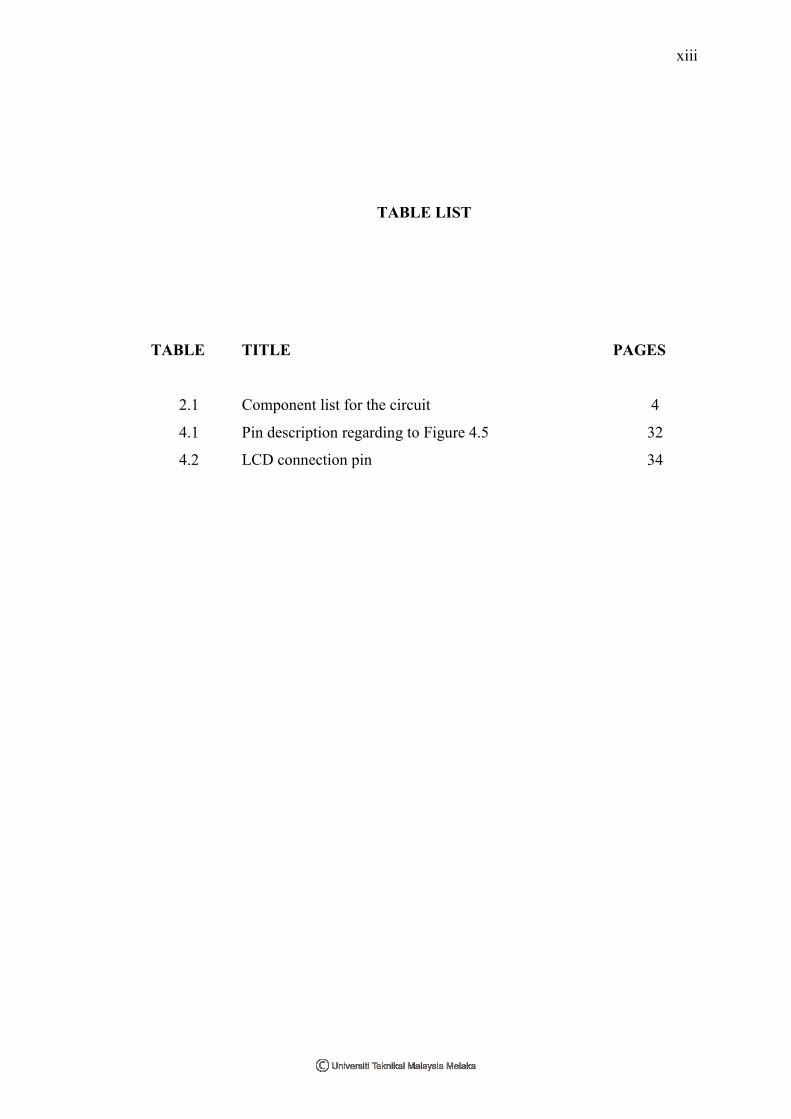
TABLE LIST
TABLE TITLE PAGES
2.1 Component list for the circuit 4
4.1 Pin description regarding to Figure 4.5 32
4.2 LCD connection pin 34

xiv
FIGURE LIST
FIGURE TITLE PAGES
2.1 Temperature Controlled Auto Fan [1] 4
2.2 Automatic Temperature Controlled Fan 6
2.3 Temperature Monitoring Control System 8
2.4 Automatic Temperature Controlled Fan 9
2.5 Automatic Temperature Controlled Fan 11
2.6 PIC burner 15
2.7 PIC16F876A 16
2.8 LM35DZ schematic diagram 16
3.1 Flowchart of project methodology 19
3.2 Continue from flowchart of project methodology 20
3.3 Several components that related to circuit project 22
3.4
3.5
Process of communication between man and a PIC
MP LAB IDE Desktop
23
24
3.6 Circuit design with the ISIS 7 Professional 26
3.7
3.8
3.9
PCB Design with ARES 7 Professional
Circuit Construction on Breadboard
Complete Prototype
26
27
28
4.1 Block diagram for the circuit 30
4.2 Circuit Diagram 30
4.3 Connection for LM35 31
4.4 Pin position for LM35 31
4.5 Pin position for BD 135 32
xv
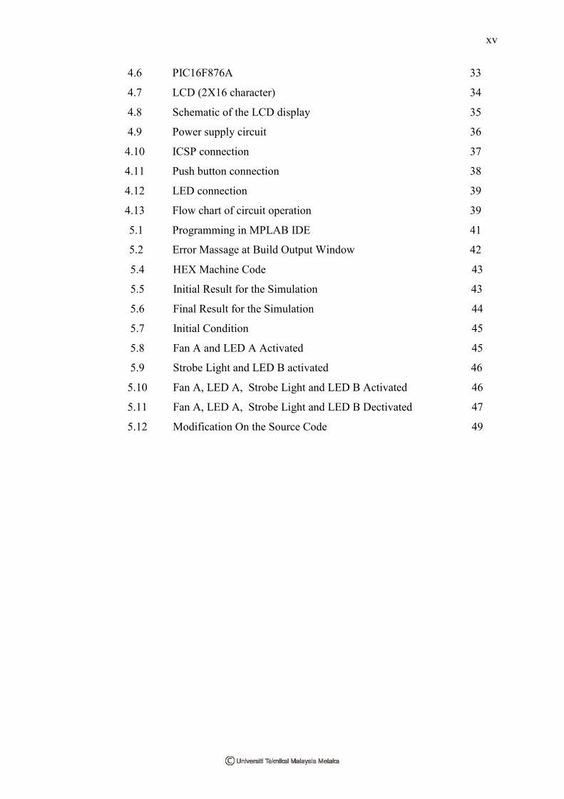
4.6 PIC16F876A 33
4.7 LCD (2X16 character) 34
4.8 Schematic of the LCD display 35
4.9 Power supply circuit 36
4.10 ICSP connection 37
4.11 Push button connection 38
4.12 LED connection 39
4.13 Flow chart of circuit operation 39
5.1
5.2
Programming in MPLAB IDE
Error Massage at Build Output Window
41
42
5.4 HEX Machine Code 43
5.5 Initial Result for the Simulation 43
5.6 Final Result for the Simulation 44
5.7 Initial Condition 45
5.8 Fan A and LED A Activated 45
5.9 Strobe Light and LED B activated 46
5.10 Fan A, LED A, Strobe Light and LED B Activated 46
5.11 Fan A, LED A, Strobe Light and LED B Dectivated 47
5.12 Modification On the Source Code 49
xvi
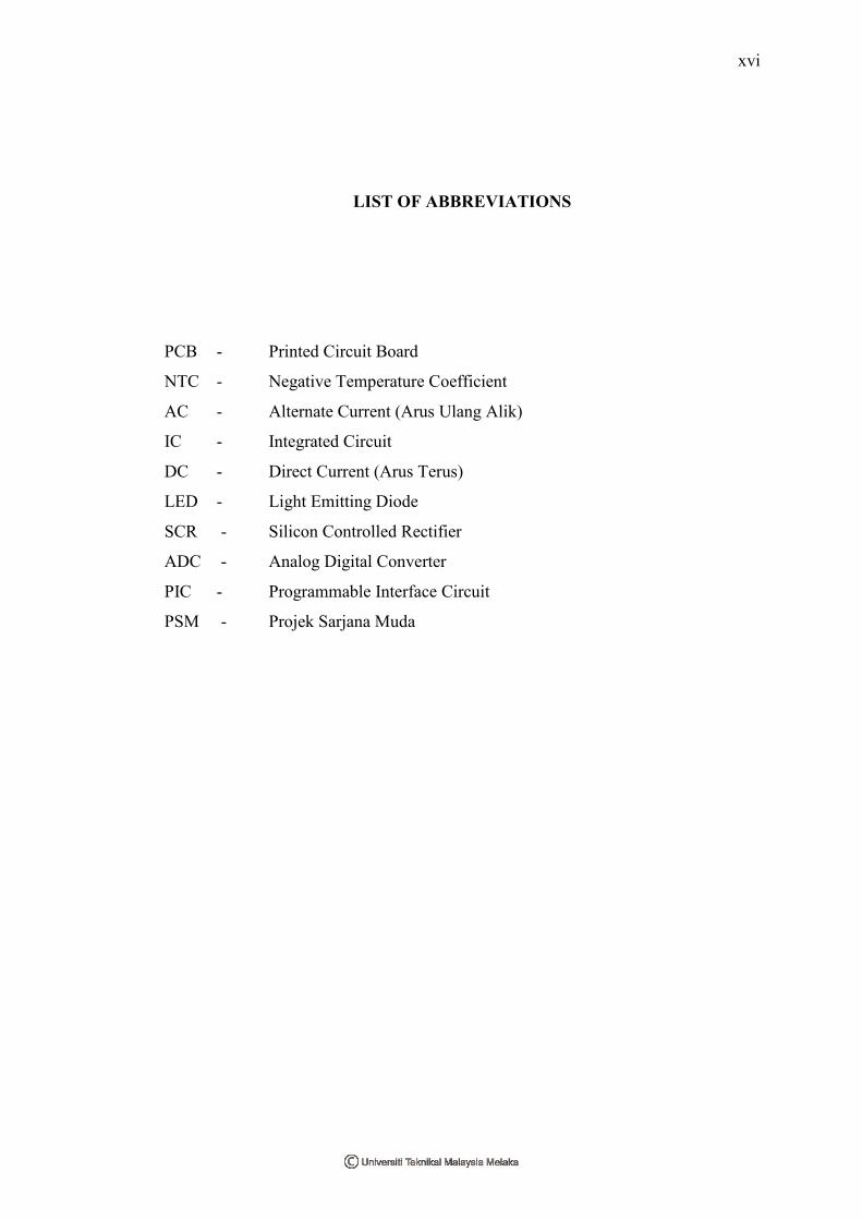
LIST OF ABBREVIATIONS
PCB - Printed Circuit Board
NTC - Negative Temperature Coefficient
AC - Alternate Current (Arus Ulang Alik)
IC - Integrated Circuit
DC - Direct Current (Arus Terus)
LED - Light Emitting Diode
SCR - Silicon Controlled Rectifier
ADC - Analog Digital Converter
PIC - Programmable Interface Circuit
PSM - Projek Sarjana Muda

xvii
APPENDIX LIST
APPENDIX TITLE PAGES
A PIC16F876A Data sheet 54
B LM35DZ temperature sensor Data sheet 58
C COMPONENTS PRICE ESTIMATION 61
D Source Code 62
E Gantt Chart 70
1
CHAPTER I
INTRODUCTION
1.1 PROJECT BACKGROUND
Room temperature (also referred to as ambient temperature) is a common
term to denote a certain temperature within enclosed space at which humans are
accustomed. Room temperature is thus often indicated by general human comfort,
with the common range of 22°C (71.6 °F) to 28°C (82.4 °F), though climate may
acclimatize people to higher or lower temperatures. For human comfort, desirable
room temperature greatly depends on individual needs and various other factors.
Because of changing effect of temperature, an automatic control room temperature is
needed to solve the problem of uncomfortable for human life.
1.2 PROJECT OBJECTIVES
Due to the problem statement, it’s cleared that the objectives of the project is:
1. To design an accurate and sensitive circuit to control the room’s temperature
according to any changes of temperature. The suitable reference temperature
is in the range of 22°C to 28°C.
2. To simulate the simplest temperature controller circuit with specific software.
2
1.3 PROBLEM STATEMENTS
Room temperature always changes and sometimes it occurs drastically (for
example: rainy day at the night). Thus, uncomfortable environment will be happen to
the human life. Secondly, human aided control are commonly use but in certain time
there are some unexpected matter occur. For this reason, automatic control system is
needed. Another that the circuit of automatic control room temperature previously is
less stable and less sensitive. Thus the measurement temperature of the circuit is also
not accurate.
1.4 SCOPES OF WORK
This project will focus on controlling temperature changing inside a room and
speed changing for the fan. Temperature sensor and microcontroller are the main
components to execute the task. Thus, the function and operation of temperature
sensor (type: LM35DZ) and microcontroller PIC16F876A will be study to
accomplish this project. Four conditions of temperature had chosen to implement in
this project. A signal from the input (temperature sensor) will be sent to
microcontroller and microcontroller will be sent back the action signal to increase or
decrease the fan’s speed according to the temperature. In order to relate the hardware
(temperature sensor and microcontroller) with the software, the understanding of
source code that will be create using C compiler like MikroC or MPLAB IDE/PICC-
Lite is also important. The function of the compiler is to translate C language
commands to HEX machine code.

3
CHAPTER II
LITERATURE REVIEW
2.1 Introduction
Literature Review is important in each project as a base for gathering
information necessary to complete the project. All information is gathered from
various sources such as:-
1. Journal
2. Books
3. Conference Transcript
4. Thesis
5. Patent
6. Website
After searching through all this various material, all information will be
filtered to be related to automatic controlled room temperature. The information that
will be focused on this chapter is about some reference circuit of automatic
controlled room temperature and its main components that to be used.

4
2.2 Reference Circuit 1
Figure 2.1 Temperature Controlled Auto Fan [1]
Table 2.1 Component list for the circuit
Part Description NotesIC1 LM741 Op-Amp NE741,µA741, etc.Q1 2N2222A transistor See textD1 1N4148 Diode 1N4001, or othersTh1 50K Thermistor KC005T in prototypeRe1 12V Relay RS is 1AR1 15K, 5% resistor brown-green-orange
R2,R5 10K, 5% resistor brown-black-orangeR3 150K, 5% resistor brown-green-yellowR4 4K7, 5% resistor yellow-purple-redR6 1K, 5% resistor brown-black-redR7 1K8, 5% resistor brown-gray-redP1 100K Trimmer Pot BournsC1 10uF/25V Capacitor ElectrolyticC2 0.01uF, Capacitor CeramicLed Red, 3mm Light Emitting Diode
5
Figure 2.1 show a circuit of Temperature Controlled Auto Fan design by Tony
Van Roon [1]. This circuit uses one temperature sensor, thermistor 48K made by
Fenwal (#197-503LAG-A01). This 48K was measured at exactly 25°C and with 10%
tolerance. The resistance increases as the surrounding temperature decreases.
Another name for this thermistor is 'NTC'. NTC stands for "Negative Temperature
Coefficient" which means when the surrounding temperature decreases the resistance
of this thermistor will increase. P1 is a regular Bourns trimmer and adjusts a wide
range of temperatures for this circuit. R1 is a 'security' resistor just in case the
trimmer pot P1 is adjusted all the way to '0' ohms. At which time the thermistor
would get the full 12 volt and it will get too hot [1].
The function of R3 is to feeds a bit of hysteresis back into the op-amp to
eliminate relay 'chatter' when the temperature of the thermistor reaches its threshold
point. Depending on which application and the type to use for Q1 and Re1, start with
330K or so and the value is adjusted it’s downwards until it satisfied. The value of
150K shown in the diagram worked for this circuit. Decreasing the value of R2
means more hysteresis, just don't use more then necessary. Or temporarily use a
trimmer pot and read off the value. In this case 120K is suitable fot this circuit.
Transistor Q1 can be a 2N2222(A), 2N3904, NTE123A, and ECG123A. Not critical
at all. It acts only as a switch for the relay so almost any type will work, as long as it
can provide the current needed to activate the relay's coil [1].
For the diode, D1 the 1N4148, acts as a spark arrestor when the contacts of the
relay open and eliminates false triggering. For this application the 1N4148 was good
enough since the tiny relay that had used was only 1 amp. However, the large variety
of diodes can be as next choice for example 1N4001 or something and should be
used if your relay type can handle more then 1 amp. This circuit was designed to
automatically activate a set of three or four small DC fans to cool a large cool-rib for
a 10 Amp power supply. It can be used in a variety of other applications as well [1].

6
2.3 Reference Circuit 2
Figure 2.2 Automatic Temperature Controlled Fan
7
Here (Figure 2.2) is a circuit through which the speed of a fan can be linearly
controlled automatically, depending on the room temperature. The circuit is highly
efficient as it uses thyristors for power control. Alternatively, the same circuit can be
used for automatic temperature controlled AC power control. In this circuit, the
temperature sensor used is an NTC thermistor, i.e. one having a negative temperature
coefficient. The value of thermistor resistance at 25°C is about 1 kilo-ohm. Op-amp
A1 works as current-to-voltage converter and converts temperature variations into
voltage variations. Other side, Op-amps A2, A3 and A4 work as an instrumentation
amplifier to amplify the change in voltage due to change in temperature [2].
The combination of resistor R2 and diode D2 is used for generating reference
voltage as we want to amplify only change in voltage due to the change in
temperature. Op-amp µA741 (IC2) works as a comparator. One input to the
comparator is the output from the instrumentation amplifier while the other input is
the stepped down, rectified and suitably attenuated sample of AC voltage. IC2 also
functions as a pulse width modulator in this circuit. The output from the comparator
is coupled to an optocoupler, which in turn controls the AC power delivered to fan
(load) [2].
The circuit has a high sensitivity and the output RMS voltage (across load)
can be varied from 120V to 230V (for a temp. range of 22 to 36°C), and hence wide
variations in speed are available. VR1 and VR2 can be adjusting to a desired value
for any given temperature the speed of fan (i.e. voltage across load). VR1 should be
initially kept in its mid position to realize a gain of approximately 40 from the
instrumentation amplifier. It may be subsequently trimmed slightly to obtain linear
variation of the fan speed [2].