automatic railway crossing system - latest seminar topics ... · automatic railway crossing system...
TRANSCRIPT
Automatic Railway Crossing System Page | i
Automatic Railway Crossing System
Submitted by
1. Patel Nimeshkumar Rameshbhai (080290109038)
2. Patel Tejaskumar Manubhai (090293109003)
3. Patel Gajendrakumar Madhabhai (080290109005)
4. Jayswal Nitishkumar Maheshkumar (080290109024)
Guided by
Mr. Maheshbhai S. Patel
Assistant Prof
Specialization in M.E. in Electrical Power system
In fulfillment for the award of the degree
Of
BACHELOR OF ENGINEERING
In
Department of Electrical Engineering
L. C. Institute of Technology, Bhandu – 384 120 Ta: Visnagar, Dist.: Mahesana,
Gujarat, India
Gujarat Technological University, Ahmedabad
April, 2012
Automatic Railway Crossing System Page | ii
CERTIFICATE
This is to certify that the dissertation entitled "AUTOMATIC RAILWAY CROSSING
SYSTEM” has been carried out by Mr. Patel Nimeshkumar Rameshbhai (Enrollment No. : -
080290109038) at L. C. Institute of Technology, Bhandu under my guidance in fulfillment of the
degree of Bachelor of Engineering in ELECTRICAL ENGINEERING (7th Semester/8th Semester)
of Gujarat Technological University, Ahmedabad during the academic year 2011-12.
Date:
Signature and Name of Guide Signature and Name of Head of Department
Seal of Institute
Automatic Railway Crossing System Page | iii
CERTIFICATE
This is to certify that the dissertation entitled "AUTOMATIC RAILWAY CROSSING
SYSTEM” has been carried out by Mr. Patel Tejaskumar Manubhai (Enrollment No.:-
090293109003) at L. C. Institute of Technology, Bhandu under my guidance in fulfillment of the
degree of Bachelor of Engineering in ELECTRICAL ENGINEERING (7th Semester/8th Semester)
of Gujarat Technological University, Ahmedabad during the academic year 2011-12.
Date:
Signature and Name of Guide Signature and Name of Head of Department
Seal of Institute
Automatic Railway Crossing System Page | iv
CERTIFICATE
This is to certify that the dissertation entitled "AUTOMATIC RAILWAY CROSSING
SYSTEM” has been carried out by Mr. Jayswal Nitishkumar Maheshkumar (Enrollment No.:-
080290109005) at L. C. Institute of Technology, Bhandu under my guidance in fulfillment of the
degree of Bachelor of Engineering in ELECTRICAL ENGINEERING (7th Semester/8th Semester)
of Gujarat Technological University, Ahmedabad during the academic year 2011-12.
Date:
Signature and Name of Guide Signature and Name of Head of Department
Seal of Institute
Automatic Railway Crossing System Page | v
CERTIFICATE
This is to certify that the dissertation entitled "AUTOMATIC RAILWAY CROSSING
SYSTEM” has been carried out by Mr. Patel Gajendrakumar Madhbhai (Enrollment No.:-
080290109024) at L. C. Institute of Technology, Bhandu under my guidance in fulfillment of the
degree of Bachelor of Engineering in ELECTRICAL ENGINEERING (7th Semester/8th Semester)
of Gujarat Technological University, Ahmedabad during the academic year 2011-12.
Date:
Signature and Name of Guide Signature and Name of Head of Department
Seal of Institute
Automatic Railway Crossing System Page | vi
ACKNOWLEDGEMENT
During this project work, we would like to project report on the title-AUTOMATIC RAILWAY
CROSSING SYSTEM, We acknowledge with sincere thanks to our project guide M.S. Patel for
excellent guidance and selfless efforts. Without their co-operative attitude, constant inspiration and
dedicated at each and every stage of this project it would not possible to make this project complete.
We would also like to express our gratitude and thanks toward the staff and H.O.D. of Electrical
Engineering department for their supper. In this project my parents & my friend‟s also help to me I
also thanks to that for helping me support.
By
Nimesh R. Patel (080290109038)
Tejas M. Patel (090293109003)
Nitish M. Jayswal (080290109005)
Gajendra M. Patel (080290109024)

Automatic Railway Crossing System Page | vii
ABSTRACT
The objective of this project is to provide an automatic railway gate at a level crossing replacing the
gates operated by the gatekeeper. It deals with two things. Firstly, it deals with the reduction of time
for which the gate is being kept closed. And secondly, to provide safety to the road users by reducing
the accidents.
By the presently existing system once the train leaves the station, the stationmaster informs the
gatekeeper about the arrival of the train through the telephone. Once the gatekeeper receives the
information, he closes the gate depending on the timing at which the train arrives. Hence, if the train
is late due to certain reasons, then gate remain closed for a long time causing traffic near the gates.
By employing the automatic railway gate control at the level crossing the arrival of the train is
detected by the sensor placed near to the gate. Hence, the time for which it is closed is less compared
to the manually operated gates and also reduces the human labor. This type of gates can be employed
in an unmanned level crossing where the chances of accidents are higher and reliable operation is
required. Since, the operation is automatic; error due to manual operation is prevented Automatic
railway gate control is highly economical microcontroller based arrangement, designed for use in
almost all the unmanned level crossings in the country.
Automatic Railway Crossing System Page | viii
TABLE OF CONTENTS
Title Page i
Certificate Page ii
Acknowledgements vi
Abstract vii
Table of Contents viii
List of Figures x
List of Tables xi
Chapter 1 Introduction 1
1.1 Introduction 1
1.2 Automatic control system 1
1.3 Working of automatic control system 2
Chapter 2 Overview of project 3
2.1 Introduction of oldest technique 3
2.2 Introduction of automatic railway crossing system 4
2.3 Basic block diagram of automatic railway crossing system 5
2.4 Working of block diagram 6
2.5 Working of block diagram 8
Chapter 3 Basic block diagram design 9
3.1 Circuit diagram of power supply circuit 9
3.2 Description of Power Circuit Diagram 9
3.3 Simulation of power circuit in Protious 11
3.4 Circuit diagram of automatic railway crossing system 12
3.4.1 Description of main circuit 14
3.4.2:- Sensor connection diagram on IC LM324 14
3.4.3:- Working of main circuit 15
Chapter 4 Detail of equipment 16
4.1 Introduction 16
4.2 Microcontroller AT89S52 16
4.2.1 Description 16
4.2.2 Pin diagram of microcontroller AT89S52 17
Automatic Railway Crossing System Page | ix
4.2.3 Block diagram of AT89S52 18
4.2.4 Pin Description 19
4.2.5 Special Function Registers 24
4.2.6 Memory organization 25
4.2.7 Interrupts 26
4.2.8 Features 27
4.3 PIR Motion sensor 28
4.4 IC LM324 30
4.5 IC LM7805 31
4.6 IC L293D 33
4.7 Infrared sensor 35
Chapter 5 Conclusion and future work 36
APPENDIX A: Programming code 37
APPENDIX B: Photograph of hardware 43
References 47
Automatic Railway Crossing System Page | x
LIST OF FIGURES
Fig. No. Fig. Name Page No.
2.1 Single diagram of oldest railway crossing technique 3
2.2 Basic block diagram of automatic railway crossing System 5
2.3 Simple block diagram of system 6
3.1 Schematic diagram of supply circuit 9
3.2 Power simulation circuit in protious 11
3.3 Schematic diagram of main circuit of automatic Railway crossing system 12
3.4 Schematic diagram for sensor circuit 13
3.5 Sensor connection diagram 14
4.1 Pin diagram of Microcontroller AT89S52 17
4.2 Block diagram of Microcontroller AT89S52 18
4.3 Oscillator connection 23
4.4 External clock drive configuration 23
4.5 Symbol and equivalent circuit of crystal 24
4.6 PIR motion sensor 29
4.7 Pin diagram of LM324 IC 30
4.8 Pin diagram of LM7805 IC 31
4.9 Inter block diagram of IC LM7805 32
4.10 Pin diagram of IC L293D 33
4.11 H bridge connection diagram of motor driver IC 34
Automatic Railway Crossing System Page | xi
LIST OF TABLE
Table No. Name Page No.
4.1 Alternating function of port 1 20
4.2 Alternating function of port 3 21
4.3 Pin configuration of PIR motion sensor 29

Automatic Railway Crossing System Page | 1
Chapter 1: INTRODUCTION
1.1:- Introduction
Now a days, India is the country which having world‟s largest railway network. Over
hundreds of railways running on track every day. As railway has straightway running as
well as it has somewhat risky and dangerous as per as general public and traffic concern.
As we know that it is surely impossible to stop the running train at instant is some critical
situation or emergency arises. Therefore at the places of traffic density, suburban areas
and crossings there is severe need to install a railway gate in view of protection purpose.
Obviously at each and every gate there must be an attendant to operate and maintain it.
But, India, our country is a progressive country. It has already enough economical
problems which are ever been unsolved. So, to avoid all these things some sort of
automatic and independent system comes in picture. Now a day‟s automatic system
occupies each and every sector of applications as it is reliable, accurate and no need to
pay high attention.
So, keeping all these things and aspects and need of such system our project batch tries to
make such type of system with the help of various electrical, electronic and mechanical
components. The thorough and detail in formation as per as construction and working is
concerned, it is discussed fatherly.
1.2:- Automatic control system
An automatic control system is an arrangement of physical components connected in
such a manner so as to direct or regular itself or some another system i.e. some controlled
condition forming part of the system is maintained in a prescribed manner. Automatic
control system has influenced the current way of life. In recent year automatic control
systems have been rapidly increasing importance in all fields of engineering. Its
application covers a very wide range from design of precision control devices to design
of massive equipments used for manufacture of steel and other industries.
Automatic Railway Crossing System Page | 2
Advantages of automatic control system:
The need of automation is due to or advantages of automatic control system are:
1. It results in economy of operation.
2. Elimination of human error.
3. If frees human beings from mental tasks.
4. Saving in energy requirements.
5. Increase in efficiency
1.3:-Working of automatic rail control system
In this project to lift the railway crossing gate D.C. series motor. Gear arrangement is
used. The IR sensor at two points on the either side of railway crossing gate is used. The
IR sensor transmitter transmit the signal which placed in engine and gard, and IR receiver
is placed on track which received a data and complete the circuit when railway will pass
through it and the gate will be closed and similarly when the rail will pass through the
another receiver which is mounted on the other side of gate, the receiver take a signal to
controller and get operated. Hence the motor will operate and with help of gear, and the
gate will open. In this way the automatic operation of gate takes place. The gate which is
unguarded, at such place the percentage of accidents is more. Therefore to overcome
this problem this system is capable. As it is fully automatic there is no chance of failure
due to human mistake.
Automatic Railway Crossing System Page | 3
Chapter 2: OVERVIEW OF PROJECT
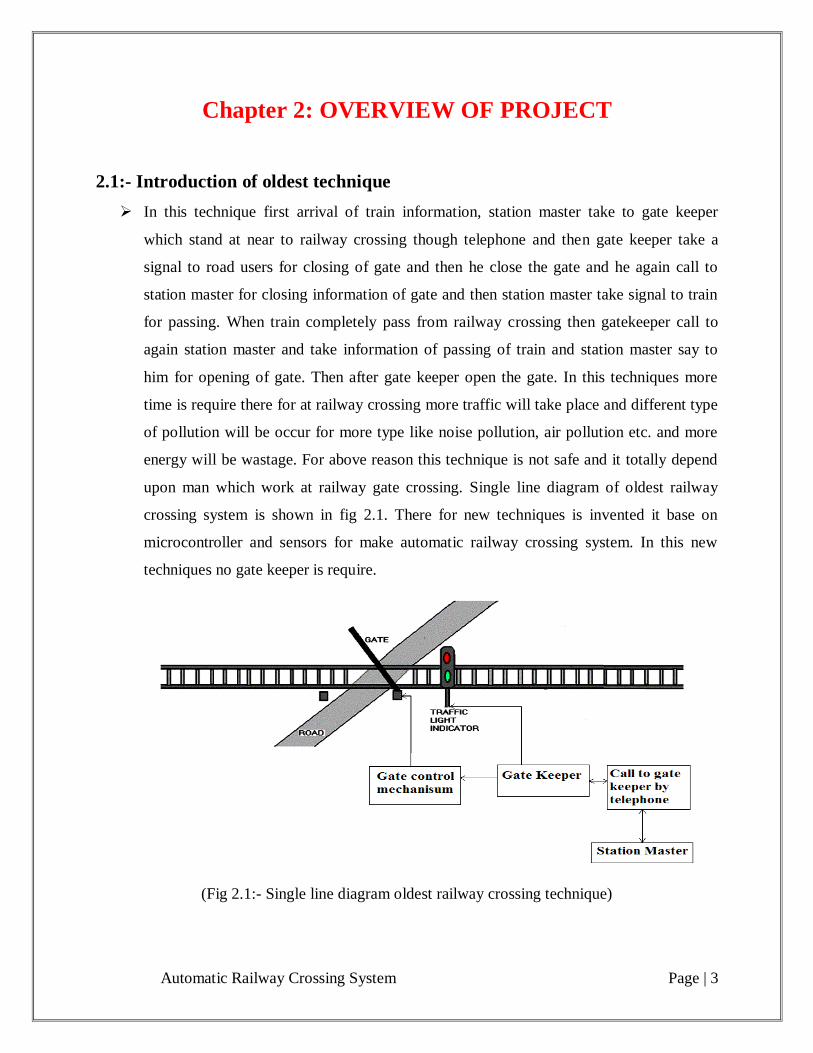
2.1:- Introduction of oldest technique
In this technique first arrival of train information, station master take to gate keeper
which stand at near to railway crossing though telephone and then gate keeper take a
signal to road users for closing of gate and then he close the gate and he again call to
station master for closing information of gate and then station master take signal to train
for passing. When train completely pass from railway crossing then gatekeeper call to
again station master and take information of passing of train and station master say to
him for opening of gate. Then after gate keeper open the gate. In this techniques more
time is require there for at railway crossing more traffic will take place and different type
of pollution will be occur for more type like noise pollution, air pollution etc. and more
energy will be wastage. For above reason this technique is not safe and it totally depend
upon man which work at railway gate crossing. Single line diagram of oldest railway
crossing system is shown in fig 2.1. There for new techniques is invented it base on
microcontroller and sensors for make automatic railway crossing system. In this new
techniques no gate keeper is require.
(Fig 2.1:- Single line diagram oldest railway crossing technique)
Automatic Railway Crossing System Page | 4
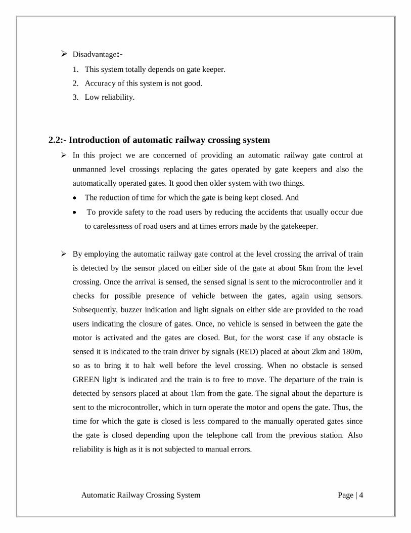
Disadvantage:-
1. This system totally depends on gate keeper.
2. Accuracy of this system is not good.
3. Low reliability.
2.2:- Introduction of automatic railway crossing system
In this project we are concerned of providing an automatic railway gate control at
unmanned level crossings replacing the gates operated by gate keepers and also the
automatically operated gates. It good then older system with two things.
The reduction of time for which the gate is being kept closed. And
To provide safety to the road users by reducing the accidents that usually occur due
to carelessness of road users and at times errors made by the gatekeeper.
By employing the automatic railway gate control at the level crossing the arrival of train
is detected by the sensor placed on either side of the gate at about 5km from the level
crossing. Once the arrival is sensed, the sensed signal is sent to the microcontroller and it
checks for possible presence of vehicle between the gates, again using sensors.
Subsequently, buzzer indication and light signals on either side are provided to the road
users indicating the closure of gates. Once, no vehicle is sensed in between the gate the
motor is activated and the gates are closed. But, for the worst case if any obstacle is
sensed it is indicated to the train driver by signals (RED) placed at about 2km and 180m,
so as to bring it to halt well before the level crossing. When no obstacle is sensed
GREEN light is indicated and the train is to free to move. The departure of the train is
detected by sensors placed at about 1km from the gate. The signal about the departure is
sent to the microcontroller, which in turn operate the motor and opens the gate. Thus, the
time for which the gate is closed is less compared to the manually operated gates since
the gate is closed depending upon the telephone call from the previous station. Also
reliability is high as it is not subjected to manual errors.
Automatic Railway Crossing System Page | 5
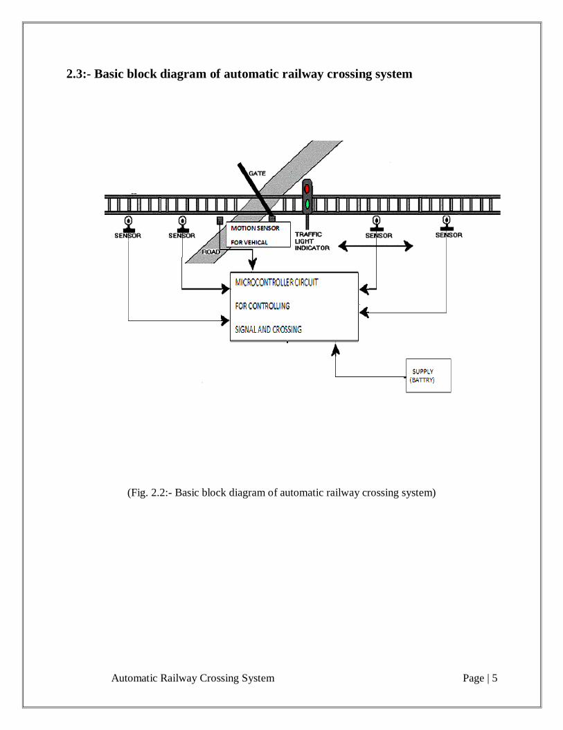
2.3:- Basic block diagram of automatic railway crossing system
(Fig. 2.2:- Basic block diagram of automatic railway crossing system)
Automatic Railway Crossing System Page | 6
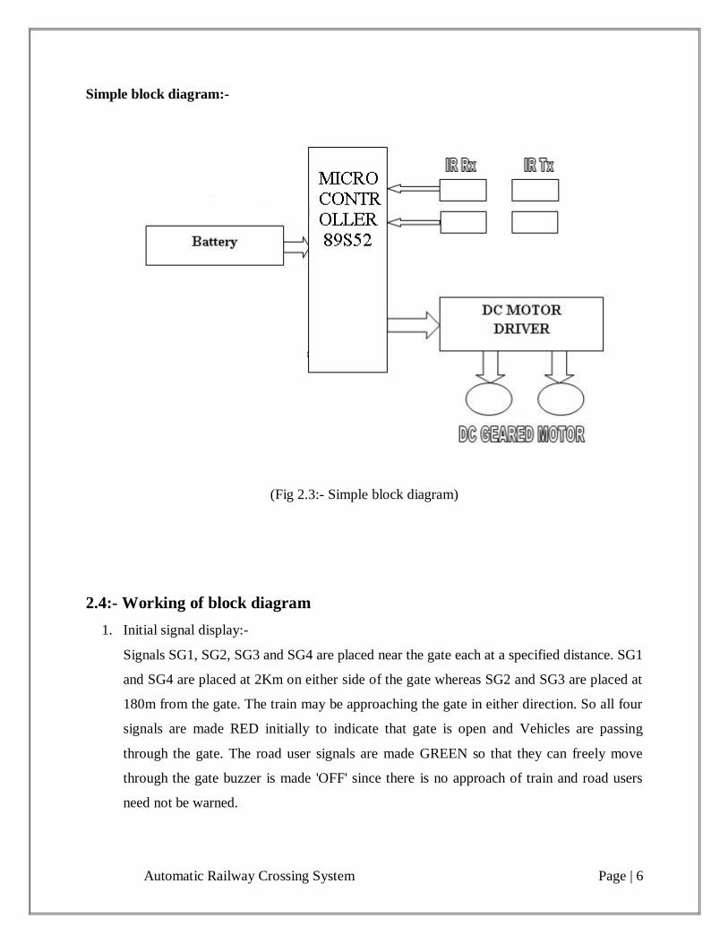
Simple block diagram:-
(Fig 2.3:- Simple block diagram)
2.4:- Working of block diagram
1. Initial signal display:-
Signals SG1, SG2, SG3 and SG4 are placed near the gate each at a specified distance. SG1
and SG4 are placed at 2Km on either side of the gate whereas SG2 and SG3 are placed at
180m from the gate. The train may be approaching the gate in either direction. So all four
signals are made RED initially to indicate that gate is open and Vehicles are passing
through the gate. The road user signals are made GREEN so that they can freely move
through the gate buzzer is made 'OFF' since there is no approach of train and road users
need not be warned.
Automatic Railway Crossing System Page | 7
2. Train arrival detections:-
The Detection of a train total four R1, R2, R3 and R4 sensors required. R1 arrival and R3
departure of train by the sensors. In the same way, R4 senses the approach and R2 the
departure respectively in the other direction of train arrival.
3. Warning for road users:-
At the moment the train arrival is sensed on either side of the gate, road users are warned
about the train approach by RED signals placed to caution the road users passing through
the gate. RED signal appears for the road user once the train cuts the sensor placed 5Km
before the gate. A buzzer is made ON as a precautionary measure for the road user and
that nobody should enter the gate at that moment.
4. Sensing for vehicles:-
For sensing the vehicle on railway crossing system uses a motion sensor. And these
motion sensors take a signal to microcontroller AT89S52. Since there is no vehicle or
obstacle, signal is made GREEN for the train to pass through the gate. The same is applied
for in the other direction and SG3 and SG4 are made GREEN and gates are closed. Due to
some unavoidable circumstances, if there is a sudden breakdown of a vehicle between the
gates, then the motion sensor sense the availability of vehicle on the crossing system . It
indicates the presence of vehicle and the signal for train should be made RED in order to
slow down the train to avoid collision. Then the obstacle should be warned to clear the
path.
5. Gate closing operation:-
Once the microcontroller senses that there is no vehicle inside, then it automatically
produces the signal to operate the motor through relay circuit and hence close the gate for
the passage of train. When any presence of obstacle is sensed, AT89S52 controller gives
signal for obstacle to clear the path and once the path is cleaned, motor is operated to close
the gate. Actually rotary motion occurs in a motor. This rotary motion is converted to
linear motion of the gate using a gear.
Automatic Railway Crossing System Page | 8
6. Signal for train:-
When the path is clear inside the gate, GREEN signal is produced for the train when there
is any obstacle; signal is made RED for the train in order to slow down its speed before 5
Km from the gate. Another signal placed at 180 m before the gate, when it is still RED
when train approaches if then provisions if then provisions should be stopping the train.
7. Train Departure Detection:-
Detection of train departure is also done using relay technique as explained under the head
of train arrival detection. Train departure sensing is done by sensors R3 and R2
respectively considering the directions of train approach.
8. Gate operating:-
When the train departure is sensed by the sensors, signal is given to the Microcontroller
which operates the motor in reverse direction and the gates are opened. Once the gate is
opened signal for road users are made GREEN so that the vehicles can pass through the
gate.
2.5:- Application
Railway gate controlling.
Parking gate controlling.
Automatic Railway Crossing System Page | 9
Chapter 3: Basic Block Diagram Design
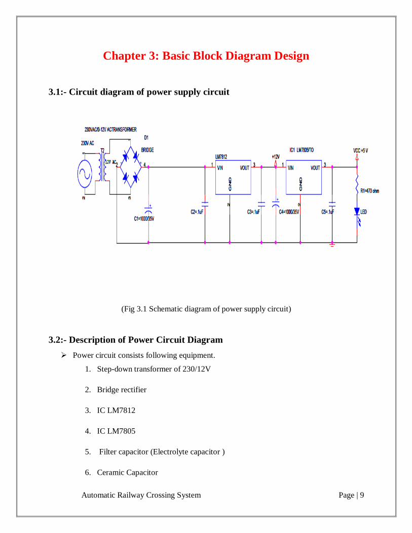
3.1:- Circuit diagram of power supply circuit
(Fig 3.1 Schematic diagram of power supply circuit)
3.2:- Description of Power Circuit Diagram
Power circuit consists following equipment.
1. Step-down transformer of 230/12V
2. Bridge rectifier
3. IC LM7812
4. IC LM7805
5. Filter capacitor (Electrolyte capacitor )
6. Ceramic Capacitor
Automatic Railway Crossing System Page | 10
The AC supply of 230V is step-downed to 12V by the step-down transformer. And the
12v is now given to bridge rectifier to convert the AC source to DC source. The bridge
rectifier consists of four diodes, which two of them comprises forward bias and other two
of them reverse bias during the positive half cycle of AC voltage. And vice versa during
the negative half cycle of the AC source. After rectification, the 12v DC is given to
regulator IC LM7812. The positive voltage regulator IC LM7812, provides a constant
12v DC to the load. This 12v DC supply is used for to drive the motor. Since the output
may be pulsated DC, the filters capacitor filters the AC components present in the output
to provide a pure DC. And ceramic capacitor used for to reduce the harmonic. Then after
another regulated IC LM7805 Is connected which provide 5v DC to the load. 5v DC
supply is used for to operate the microcontroller circuit.
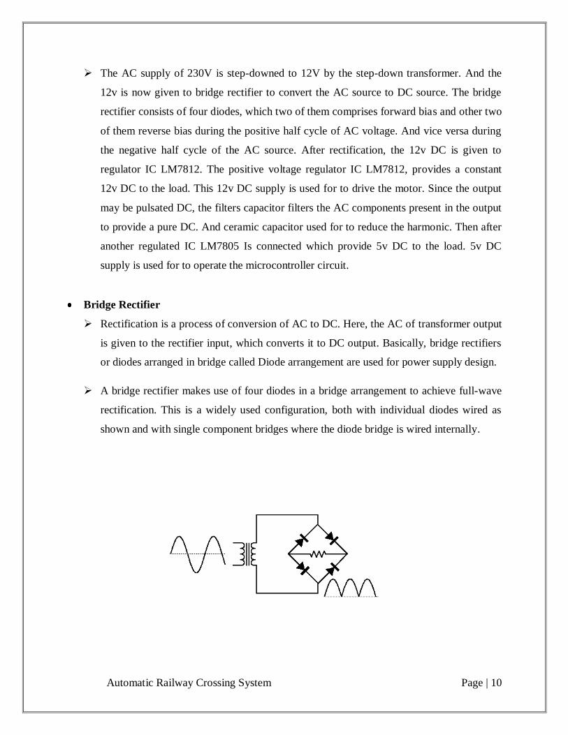
Bridge Rectifier
Rectification is a process of conversion of AC to DC. Here, the AC of transformer output
is given to the rectifier input, which converts it to DC output. Basically, bridge rectifiers
or diodes arranged in bridge called Diode arrangement are used for power supply design.
A bridge rectifier makes use of four diodes in a bridge arrangement to achieve full-wave
rectification. This is a widely used configuration, both with individual diodes wired as
shown and with single component bridges where the diode bridge is wired internally.
Automatic Railway Crossing System Page | 11
Current Flow in the Bridge Rectifier
For both positive and negative swings of the transformer, there is a forward path through
the diode bridge. Both conduction paths cause current to flow in the same direction
through the load resistor, accomplishing full-wave rectification. While one set of diodes
is forward biased, the other set is reverse biased and effectively eliminated from the
circuit.
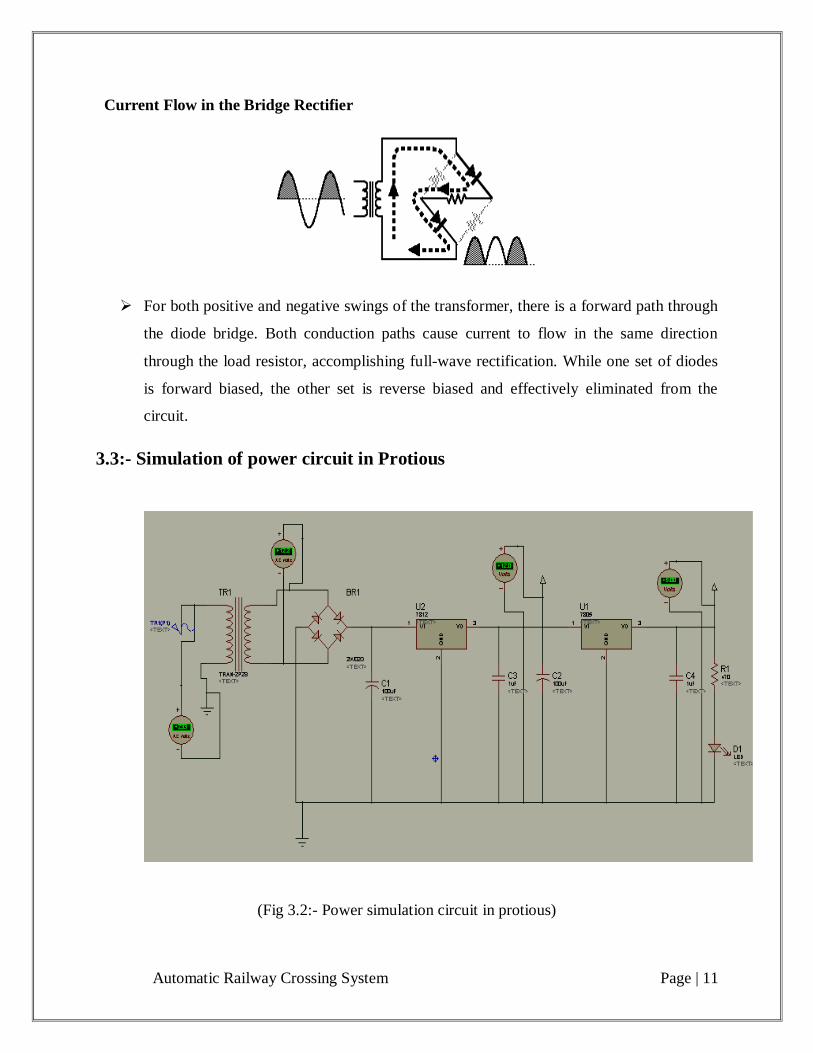
3.3:- Simulation of power circuit in Protious
(Fig 3.2:- Power simulation circuit in protious)
Automatic Railway Crossing System Page | 12
3.4:- Circuit diagram of automatic railway crossing system
Circuit diagram of main circuit
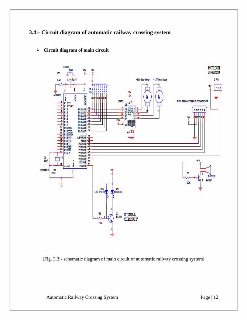
(Fig. 3.3:- schematic diagram of main circuit of automatic railway crossing system)
Automatic Railway Crossing System Page | 13
Circuit diagram of sensor circuit
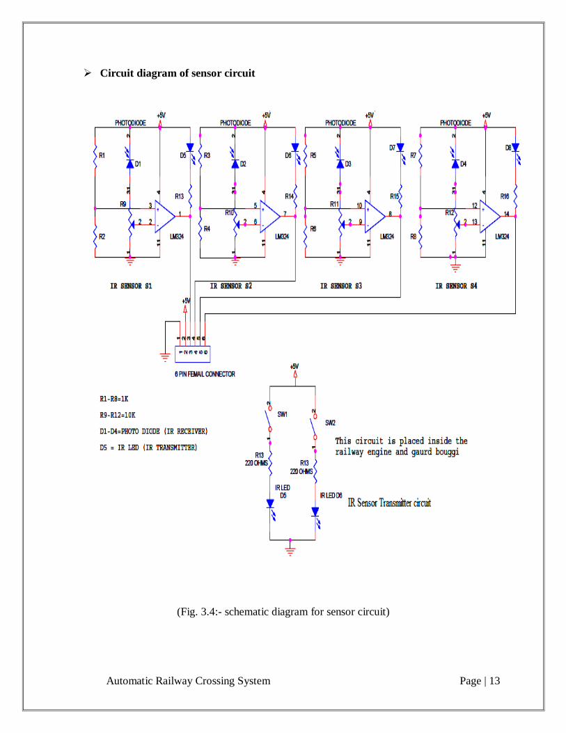
(Fig. 3.4:- schematic diagram for sensor circuit)
Automatic Railway Crossing System Page | 14
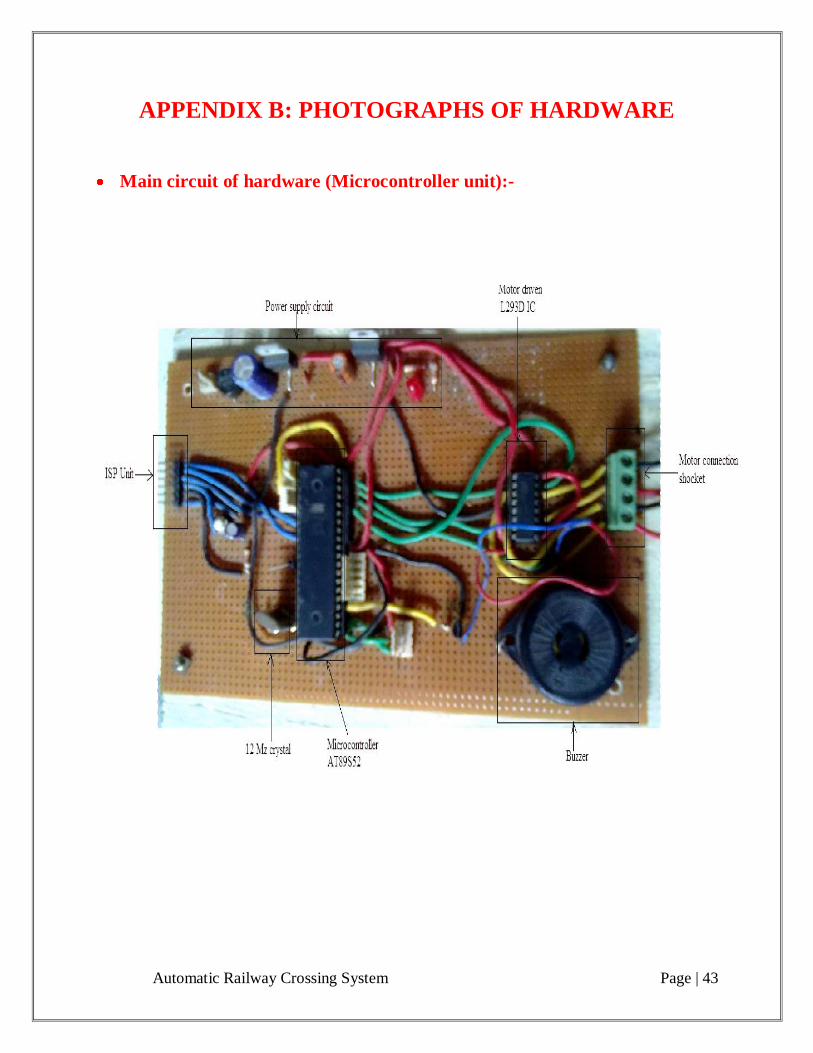
3.4.1:- Description of main circuit:-
In main circuit microcontroller unit is connected it is 40 pin IC and it have four input
output port are available. In my project we use port 0 for motor connection. IC L293D is
used for rotate the motor in by directional.
On port 2 IR sensor circuit, PIR motion sensor, buzzer and signal circuit for road user is
connected.
On XTAL1 and XTAL2 pin 12Mz crystal is connected.
On port 1 signal circuit for train is connected.
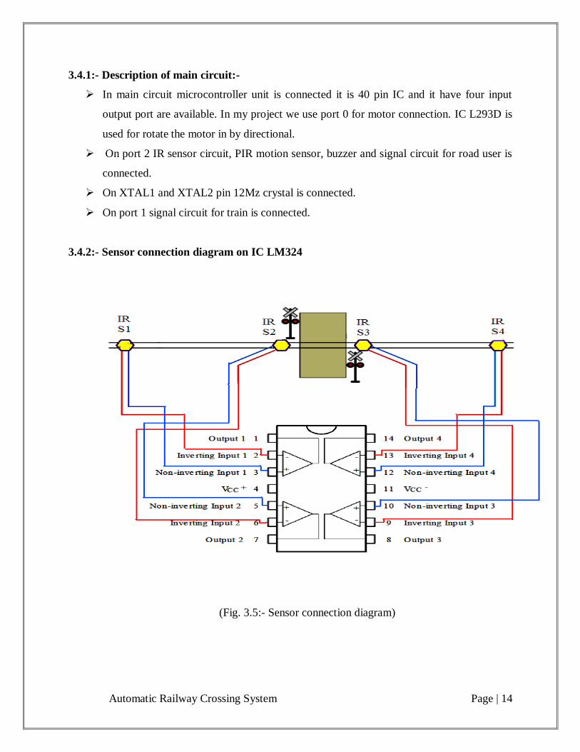
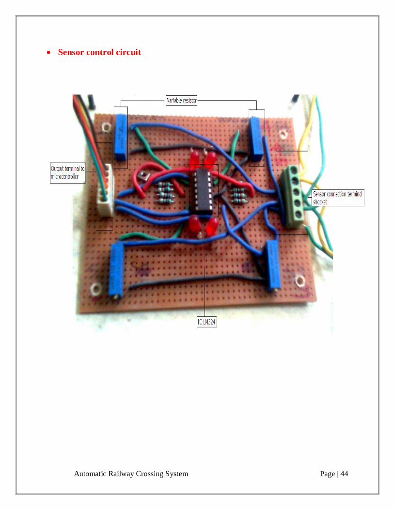
3.4.2:- Sensor connection diagram on IC LM324
(Fig. 3.5:- Sensor connection diagram)
Automatic Railway Crossing System Page | 15
3.4.3:- Working of main circuit:-
First IR sensor transmitter which are connected in railway engine and gard, and IR
receiver which are connected on track. On track four receivers are connected tow receiver
are in left side S1, S2 and another tow receiver are one right side S3, S4 of railway
crossing. S1, S4 use for closing the gate and S2, S3 use for opening the gate. Train arrival
in left side direction then sensor S1, S3 operates and for right side S4, S2 operate.
If train is come from left side. When train engine come on receiver S1 and transmitter is
transmit a signal to S1 and it take a signal to controller for arrival of train and buzzer and
motor operate then DC motor close the gate. Buzzer is take a signal to road users which
near to crossing for arrival of train. And red light of signal circuit is on which connected
on road. For closing gate I use a16 step. In 8 steps any obstacle or vehicle in working
condition on track is sense by PIR motion sensor and suddenly stop the closing of gate.
After 2sec motion sensor again check and vehicle completely pass on track than after gate
is completely closed. And then signal circuit take signal to train for pass from railway
crossing.
When train is pass from the crossing reviver S3 cont 1 when engine pass on S3 and when
gard is pass from S3 then it count 2 and receiver take a signal to controller for passing of
train and gate is open.

Automatic Railway Crossing System Page | 16
Chapter 4: Detail of equipment
4.1:- Introduction
In the automatic railway crossing system circuit fooling equipment are uses.
1) Microcontroller AT89S52
2) Infrared sensor
3) PIR Motion sensor
4) 12v 300rpm D.C. gear motor
5) 230v A.C./ 0-12v A.C. step down transformer
6) IC LM324
7) IC Lm7812
8) IC LM 7805
9) 12 MHz crystal
10) IC L293D
4.2:- Microcontroller AT89S52
4.2.1:- Description
The AT89S52 is a low-power, high-performance CMOS 8-bit microcontroller with
8Kbytes of in-system programmable Flash memory. The device is manufactured
using Atmel‟s high-density nonvolatile memory technology and is compatible with
the industry-standard 80C51 instruction set and pin out. The on-chip Flash allows the
program memory to be reprogrammed in-system or by a conventional nonvolatile
memory programmer. By combining a versatile 8-bit CPU with in-system
programmable Flash on a monolithic chip, the Atmel AT89S52 is a powerful
microcontroller which provides a highly-flexible and cost-effective solution to many
embedded control applications.
The AT89S52 provides the following standard features: 8K bytes of Flash, 256 bytes
of RAM, 32 I/O lines, Watchdog timer, two data pointers, three 16-bit timer/counters,
a six-vector two-level interrupt architecture, a full duplex serial port, on-chip
oscillator, and clock circuitry. In addition, the AT89S52 is designed with static logic
for operation down to zero frequency and supports two software selectable power
Automatic Railway Crossing System Page | 17
saving modes. The Idle Mode stops the CPU while allowing the RAM,
timer/counters, serial port, and interrupt system to continue functioning. The Power-
down mode saves the RAM contents but freezes the oscillator, disabling all other chip
functions until the next interrupt or hardware reset.
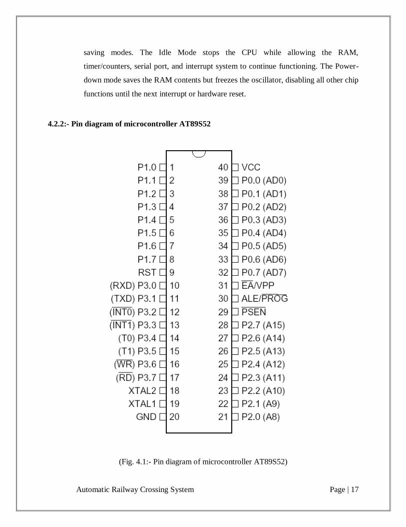
4.2.2:- Pin diagram of microcontroller AT89S52
(Fig. 4.1:- Pin diagram of microcontroller AT89S52)
Automatic Railway Crossing System Page | 18
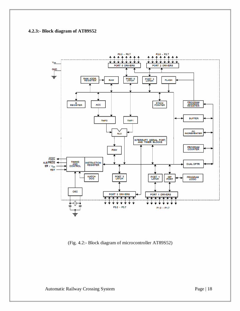
4.2.3:- Block diagram of AT89S52
(Fig. 4.2:- Block diagram of microcontroller AT89S52)

Automatic Railway Crossing System Page | 19
4.2.4:- Pin Description
VCC
Supply voltage.
GND
Ground.
Port 0
Port 0 is an 8-bit open drain bidirectional I/O port. As an output port, each pin can
sink eight TTL inputs. When 1s are written to port 0 pins, the pins can be used as high
impedance inputs.
Port 0 can also be configured to be the multiplexed low order address/data bus during
accesses to external program and data memory. In this mode, P0 has internal pull-ups.
Port 0 also receives the code bytes during Flash programming and outputs the code
bytes during program verification. External pull-ups are required during program
verification.
Port 1
Port 1 is an 8-bit bidirectional I/O port with internal pull-ups. The Port 1 output
buffers can sink/source four TTL inputs. When 1s are written to Port 1 pins, they are
pulled high by the internal pull-ups and can be used as inputs. As inputs, Port 1 pins
that are externally being pulled low will source current (IIL) because of the internal
pull-ups.
In addition, P1.0 and P1.1 can be configured to be the timer/counter 2 external count
input (P1.0/T2) and the timer/counter 2 trigger input (P1.1/T2EX), respectively, as
shown in the following table.
Port 1 also receives the low-order address bytes during Flash programming and
verification.

Automatic Railway Crossing System Page | 20
(Table 4.1:- Alternating function of port 1)
Port 2
Port 2 is an 8-bit bidirectional I/O port with internal pull-ups. The Port 2 output
buffers can sink/source four TTL inputs. When 1s are written to Port 2 pins, they are
pulled high by the internal pull-ups and can be used as inputs. As inputs, Port 2 pins
that are externally being pulled low will source current (IIL) because of the internal
pull-ups.
Port 2 emits the high-order address byte during fetches from external program
memory and during accesses to external data memory that uses 16-bit addresses
(MOVX @ DPTR). In this application, Port 2 uses strong internal pull-ups when
emitting 1s. During accesses to external data memory that uses 8-bit addresses
(MOVX @ RI); Port 2 emits the contents of the P2 Special Function Register.
Port 2 also receives the high-order address bits and some control signals during Flash
programming and verification.
Port 3
Port 3 is an 8-bit bidirectional I/O port with internal pull-ups. The Port 3 output
buffers can sink/source four TTL inputs. When 1s are written to Port 3 pins, they are
pulled high by the internal pull-ups and can be used as inputs. As inputs, Port 3 pins
that are externally being pulled low will source current (IIL) because of the pull-ups.
Automatic Railway Crossing System Page | 21
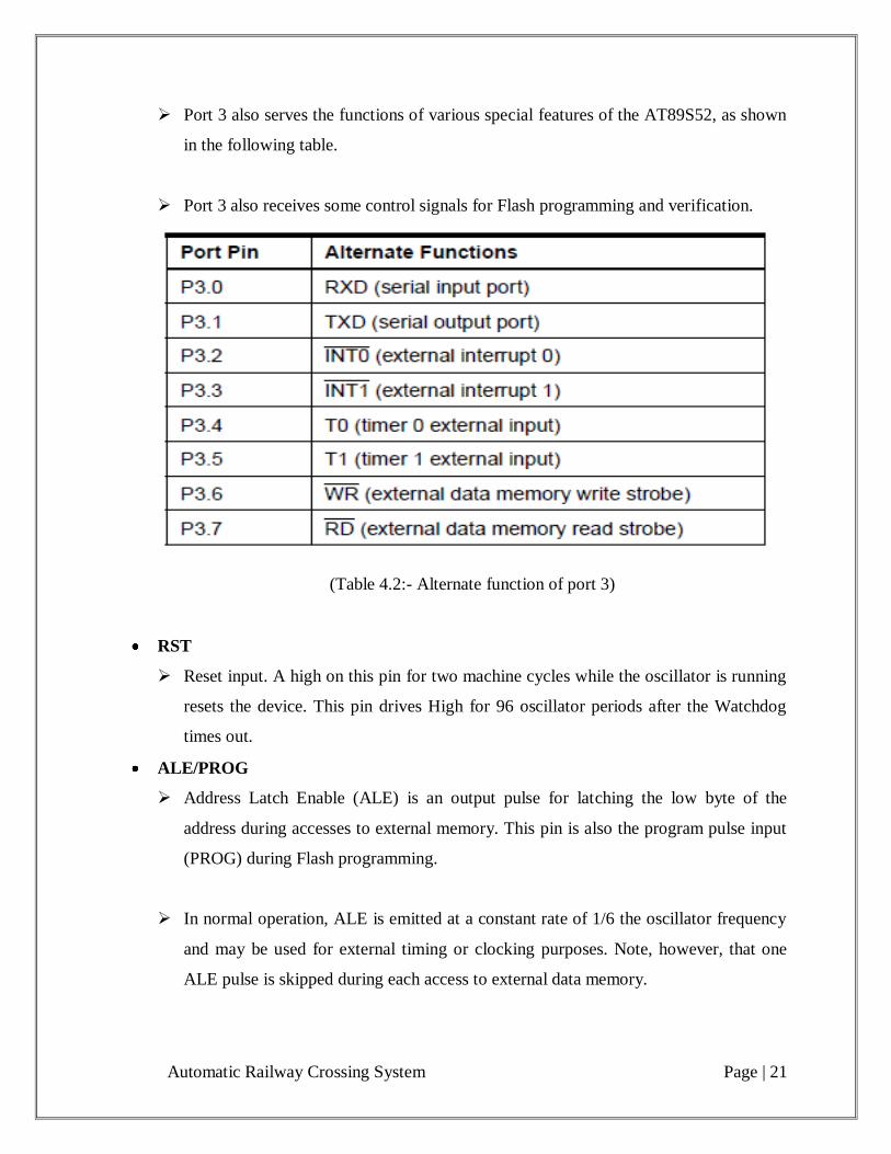
Port 3 also serves the functions of various special features of the AT89S52, as shown
in the following table.
Port 3 also receives some control signals for Flash programming and verification.
(Table 4.2:- Alternate function of port 3)
RST
Reset input. A high on this pin for two machine cycles while the oscillator is running
resets the device. This pin drives High for 96 oscillator periods after the Watchdog
times out.
ALE/PROG
Address Latch Enable (ALE) is an output pulse for latching the low byte of the
address during accesses to external memory. This pin is also the program pulse input
(PROG) during Flash programming.
In normal operation, ALE is emitted at a constant rate of 1/6 the oscillator frequency
and may be used for external timing or clocking purposes. Note, however, that one
ALE pulse is skipped during each access to external data memory.
Automatic Railway Crossing System Page | 22
If desired, ALE operation can be disabled by setting bit 0 of SFR location 8EH. With
the bit set, ALE is active only during a MOVX or MOVC Instruction. Otherwise, the
pin is weakly pulled high. Setting the ALE-disable bit has no effect if the
microcontroller is in external execution mode.
PSEN
Program Store Enable (PSEN) is the read strobe to external program memory. When
the AT89S52 is executing code from external program memory, PSEN is activated
twice each machine cycle, except that two PSEN activations are skipped during each
access to external data memory.
EA/VPP
External Access Enable. EA must be strapped to GND in order to enable the device to
fetch code from external program memory locations starting at 0000H up to FFFFH.
Note, however, that if lock bit 1 is programmed, EA will be internally latched on
reset.
EA should be strapped to VCC for internal program executions. This pin also receives
the 12-volt programming enable voltage (VPP) during Flash programming.
XTAL1
Input to the inverting oscillator amplifier and input to the internal clock operating
circuit.
XTAL2
Output from the inverting oscillator amplifier.
Oscillator characteristics
XTAL1 and XTAL2 are the input and output, respectively, of an inverting amplifier
which can be configured for use as an on-chip oscillator, as shown in Figure 1. Either
a quartz crystal or ceramic resonator may be used.
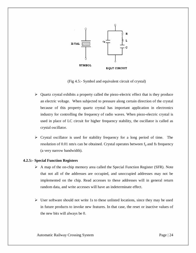
To drive the device from an external clock source, XTAL2 should be left
unconnected while XTAL1 is driven as shown in Figure 2. There are no requirements
on the duty cycle of the external clock signal, since the input to the internal clocking
Automatic Railway Crossing System Page | 23
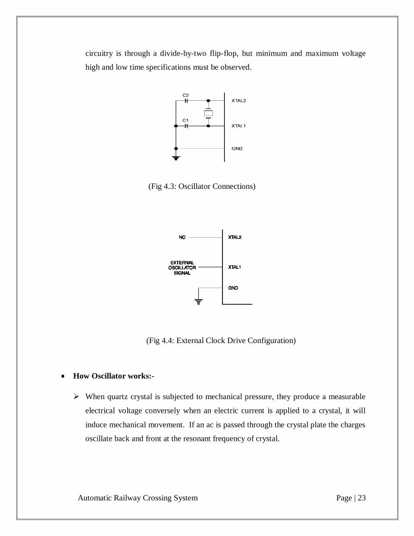
circuitry is through a divide-by-two flip-flop, but minimum and maximum voltage
high and low time specifications must be observed.
(Fig 4.3: Oscillator Connections)
(Fig 4.4: External Clock Drive Configuration)
How Oscillator works:-
When quartz crystal is subjected to mechanical pressure, they produce a measurable
electrical voltage conversely when an electric current is applied to a crystal, it will
induce mechanical movement. If an ac is passed through the crystal plate the charges
oscillate back and front at the resonant frequency of crystal.
Automatic Railway Crossing System Page | 24
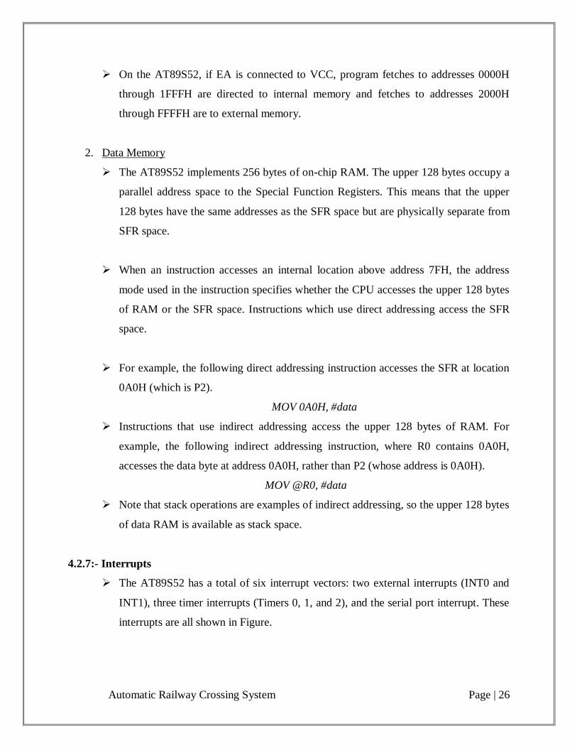
(Fig 4.5:- Symbol and equivalent circuit of crystal)
Quartz crystal exhibits a property called the piezo-electric effect that is they produce
an electric voltage. When subjected to pressure along certain direction of the crystal
because of this property quartz crystal has important application in electronics
industry for controlling the frequency of radio waves. When piezo-electric crystal is
used in place of LC circuit for higher frequency stability, the oscillator is called as
crystal oscillator.
Crystal oscillator is used for stability frequency for a long period of time. The
resolution of 0.01 nm/s can be obtained. Crystal operates between fp and fs frequency
(a very narrow bandwidth).
4.2.5:- Special Function Registers
A map of the on-chip memory area called the Special Function Register (SFR). Note
that not all of the addresses are occupied, and unoccupied addresses may not be
implemented on the chip. Read accesses to these addresses will in general return
random data, and write accesses will have an indeterminate effect.
User software should not write 1s to these unlisted locations, since they may be used
in future products to invoke new features. In that case, the reset or inactive values of
the new bits will always be 0.

Automatic Railway Crossing System Page | 25
1. Timer 2 Registers:-
Control and status bits are contained in registers T2CON (shown in Table II) and
T2MOD for Timer 2. The register pair (RCAP2H, RCAP2L) is the Capture/Reload
registers for Timer 2 in 16-bit capture mode or 16-bit auto-reload mode.
2. Interrupt Registers:-
The individual interrupt enable bits are in the IE register. Two priorities can be set for
each of the six interrupt sources in the IP register.
3. Dual Data Pointer Registers:-
To facilitate accessing both internal and external data memory, two banks of 16-bit
Data Pointer Registers are provided: DP0 at SFR address locations 82H-83H and DP1
at 84H-85H. Bit DPS = 0 in SFR AUXR1 selects DP0 and DPS = 1 selects DP1. The
user should ALWAYS initialize the DPS bit to the appropriate value before accessing
the respective Data Pointer Register.
4. Power off Flag:-
The Power off Flag (POF) is located at bit 4 (PCON.4) in the PCON SFR. POF is set
to “1” during power up. It can be set and rest under software control and is not
affected by reset.
4.2.6:- Memory Organization
MCS-51 devices have a separate address space for Program and Data Memory. Up to
64K bytes each of external Program and Data Memory can be addressed.
1. Program Memory
If the EA pin is connected to GND, all program fetches are directed to external
memory.
Automatic Railway Crossing System Page | 26
On the AT89S52, if EA is connected to VCC, program fetches to addresses 0000H
through 1FFFH are directed to internal memory and fetches to addresses 2000H
through FFFFH are to external memory.
2. Data Memory
The AT89S52 implements 256 bytes of on-chip RAM. The upper 128 bytes occupy a
parallel address space to the Special Function Registers. This means that the upper
128 bytes have the same addresses as the SFR space but are physically separate from
SFR space.
When an instruction accesses an internal location above address 7FH, the address
mode used in the instruction specifies whether the CPU accesses the upper 128 bytes
of RAM or the SFR space. Instructions which use direct addressing access the SFR
space.
For example, the following direct addressing instruction accesses the SFR at location
0A0H (which is P2).
MOV 0A0H, #data
Instructions that use indirect addressing access the upper 128 bytes of RAM. For
example, the following indirect addressing instruction, where R0 contains 0A0H,
accesses the data byte at address 0A0H, rather than P2 (whose address is 0A0H).
MOV @R0, #data
Note that stack operations are examples of indirect addressing, so the upper 128 bytes
of data RAM is available as stack space.
4.2.7:- Interrupts
The AT89S52 has a total of six interrupt vectors: two external interrupts (INT0 and
INT1), three timer interrupts (Timers 0, 1, and 2), and the serial port interrupt. These
interrupts are all shown in Figure.
Automatic Railway Crossing System Page | 27
Each of these interrupt sources can be individually enabled or disabled by setting or
clearing a bit in Special Function Register IE. IE also contains a global disable bit,
EA, which disables all interrupts at once.
Note that Table I shows that bit position IE.6 is unimplemented. User software should
not write a 1 to this bit position, since it may be used in future AT89 products.
Timer 2 interrupt is generated by the logical OR of bits TF2 and EXF2 in register
T2CON. Neither of these flags is cleared by hardware when the service routine is
vectored to. In fact, the service routine may have to determine whether it was TF2 or
EXF2 that generated the interrupt, and that bit will have to be cleared in software.
The Timer 0 and Timer 1 flags, TF0 and TF1, are set at S5P2 of the cycle in which
the timers overflow. The values are then polled by the circuitry in the next cycle.
However, the Timer 2 flag, TF2, is set at S2P2 and is polled in the same cycle in
which the timer overflows.
4.2.8:- Features:-
• 8K Bytes of In-System Programmable (ISP) Flash Memory
• 4.0V to 5.5V Operating Range
• Fully Static Operation: 0 Hz to 33 MHz
• Three-level Program Memory Lock
• 256 x 8-bit Internal RAM
• 32 Programmable I/O Lines
• Three 16-bit Timer/Counters
• Eight Interrupt Sources
• Full Duplex UART Serial Channel
• Low-power Idle and Power-down Modes
• Interrupt Recovery from Power-down Mode
• Dual Data Pointer
• Power-off Flag
Automatic Railway Crossing System Page | 28
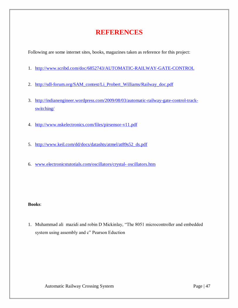
4.3:- PIR Motion sensor
General Description
The PIR (Passive Infra-Red) Sensor is a pyroelectric device that detects motion by
measuring changes in the infrared levels emitted by surrounding objects. This motion
can be detected by checking for a high signal on a single I/O pin.
Features
Single bit output
Small size makes it easy to conceal
Compatible with all Parallax microcontrollers
Application
Alarm Systems
Halloween Props
Robotics
Theory of Operation
Pyroelectric devices, such as the PIR sensor, have elements made of a crystalline
material that generates an electric charge when exposed to infrared radiation. The
changes in the amount of infrared striking the element change the voltages generated,
which are measured by an on-board amplifier. The device contains a special filter
called a Fresnel lens, which focuses the infrared signals onto the element. As the
ambient infrared signals change rapidly, the on-board amplifier trips the output to
indicate motion.
Automatic Railway Crossing System Page | 29
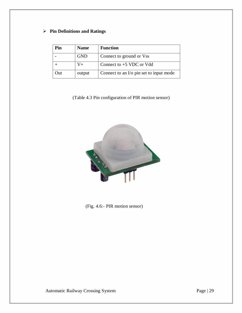
Pin Definitions and Ratings
Pin Name Function
- GND Connect to ground or Vss
+ V+ Connect to +5 VDC or Vdd
Out output Connect to an I/o pin set to input mode
(Table 4.3 Pin configuration of PIR motion sensor)
(Fig. 4.6:- PIR motion sensor)
Automatic Railway Crossing System Page | 30
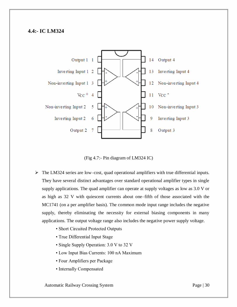
4.4:- IC LM324
(Fig 4.7:- Pin diagram of LM324 IC)
The LM324 series are low–cost, quad operational amplifiers with true differential inputs.
They have several distinct advantages over standard operational amplifier types in single
supply applications. The quad amplifier can operate at supply voltages as low as 3.0 V or
as high as 32 V with quiescent currents about one–fifth of those associated with the
MC1741 (on a per amplifier basis). The common mode input range includes the negative
supply, thereby eliminating the necessity for external biasing components in many
applications. The output voltage range also includes the negative power supply voltage.
• Short Circuited Protected Outputs
• True Differential Input Stage
• Single Supply Operation: 3.0 V to 32 V
• Low Input Bias Currents: 100 nA Maximum
• Four Amplifiers per Package
• Internally Compensated
Automatic Railway Crossing System Page | 31
• Common Mode Range Extends to Negative Supply
• Industry Standard Pin outs
• ESD Clamps on the Inputs Increase Ruggedness without Affecting Device
Operation
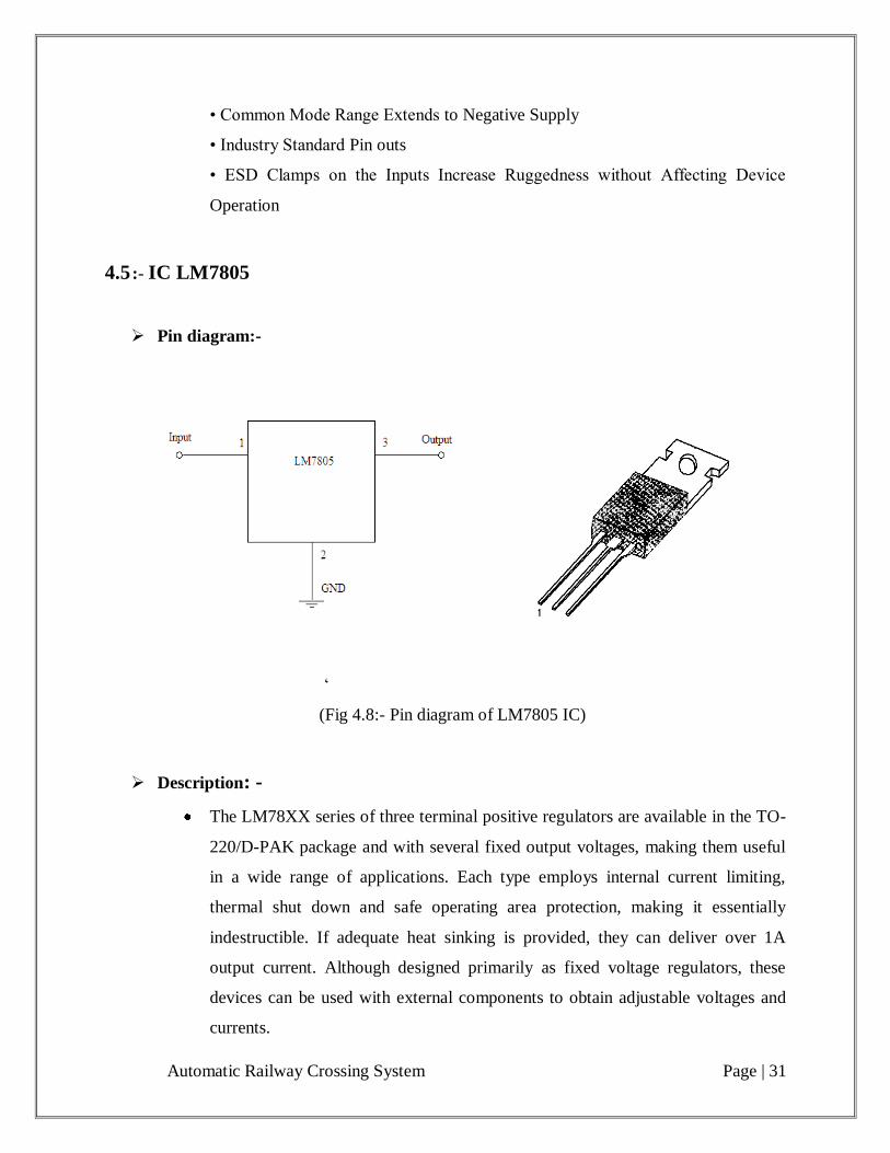
4.5 :- IC LM7805
Pin diagram:-
„
(Fig 4.8:- Pin diagram of LM7805 IC)
Description: -
The LM78XX series of three terminal positive regulators are available in the TO-
220/D-PAK package and with several fixed output voltages, making them useful
in a wide range of applications. Each type employs internal current limiting,
thermal shut down and safe operating area protection, making it essentially
indestructible. If adequate heat sinking is provided, they can deliver over 1A
output current. Although designed primarily as fixed voltage regulators, these
devices can be used with external components to obtain adjustable voltages and
currents.
Automatic Railway Crossing System Page | 32
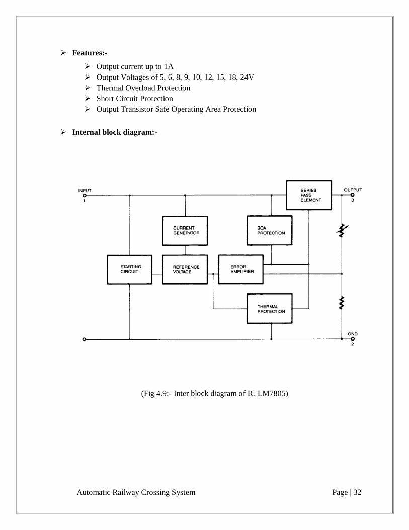
Features:-
Output current up to 1A
Output Voltages of 5, 6, 8, 9, 10, 12, 15, 18, 24V
Thermal Overload Protection
Short Circuit Protection
Output Transistor Safe Operating Area Protection
Internal block diagram:-
(Fig 4.9:- Inter block diagram of IC LM7805)
Automatic Railway Crossing System Page | 33
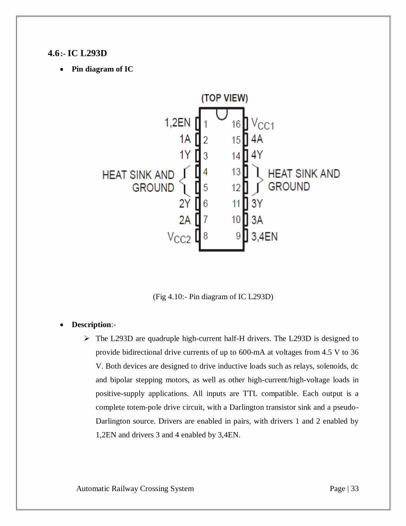
4.6 :- IC L293D
Pin diagram of IC
(Fig 4.10:- Pin diagram of IC L293D)
Description:-
The L293D are quadruple high-current half-H drivers. The L293D is designed to
provide bidirectional drive currents of up to 600-mA at voltages from 4.5 V to 36
V. Both devices are designed to drive inductive loads such as relays, solenoids, dc
and bipolar stepping motors, as well as other high-current/high-voltage loads in
positive-supply applications. All inputs are TTL compatible. Each output is a
complete totem-pole drive circuit, with a Darlington transistor sink and a pseudo-
Darlington source. Drivers are enabled in pairs, with drivers 1 and 2 enabled by
1,2EN and drivers 3 and 4 enabled by 3,4EN.
Automatic Railway Crossing System Page | 34
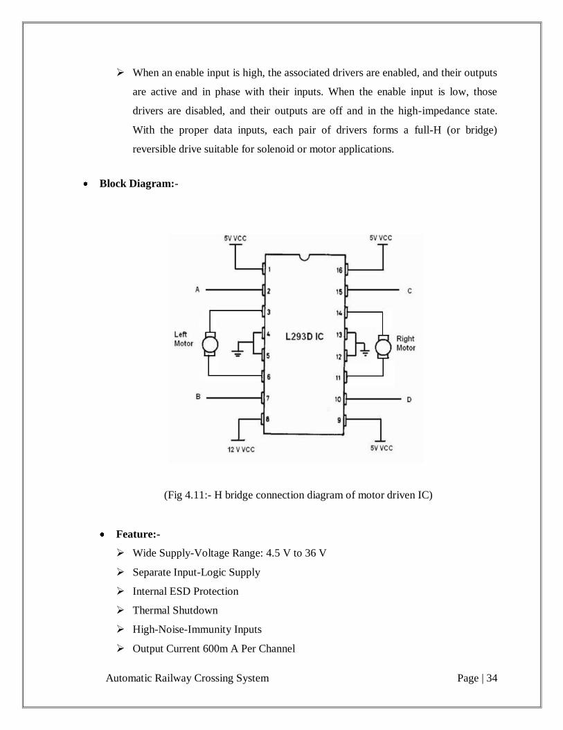
When an enable input is high, the associated drivers are enabled, and their outputs
are active and in phase with their inputs. When the enable input is low, those
drivers are disabled, and their outputs are off and in the high-impedance state.
With the proper data inputs, each pair of drivers forms a full-H (or bridge)
reversible drive suitable for solenoid or motor applications.
Block Diagram:-
(Fig 4.11:- H bridge connection diagram of motor driven IC)
Feature:-
Wide Supply-Voltage Range: 4.5 V to 36 V
Separate Input-Logic Supply
Internal ESD Protection
Thermal Shutdown
High-Noise-Immunity Inputs
Output Current 600m A Per Channel
Automatic Railway Crossing System Page | 35
Peak Output Current 1.2 A Per Channel
Output Clamp Diodes for Inductive Transient Suppression
4.7:- Infrared sensor
Infrared Radiation is electromagnetic radiation of a wavelength longer than a that of
visible light, but shorter than that of micro-wave. The name means “below red” red being
the red the color visible light with the longest wavelength. Infrared radiation has
wavelengths between about 750 nm and 1 mm, spanning five orders of magnitudes. A
longer wavelength means it has a lower frequency than red, hence “below”. Objects
generally emit infrared radiation across a spectrum of wavelengths but only a specific
region of the spectrum is of the spectrum is of interest because sensors are usually
designed only to collect radiation within a specific bandwidth.
Remote controls and IrDA device use infrared light-emitting diodes to emit infrared
radiation which is focused by a plastic lens into a narrow beam. The receiver uses a
silicon photodiode to convert the infrared radiation to an electric current. It responds only
to the rapidly pulsing signal created by the transmitter, and filters out slowly charging
infrared radiation from ambient light. IR does not penetrate walls and so does not
interfere with other devices in adjoining rooms
Automatic Railway Crossing System Page | 36
Chapter 5: Conclusion
5.1:- Conclusion:-
Using this project automatic railway crossing system we improve the rail road
transportation facility and this technique has fast operation thane oldest system and we
reduce the accident. This technique is most suitable in rural and suburban area. These
techniques do not require any gatekeeper at the railway crossing.

Automatic Railway Crossing System Page | 37
APPENDIX A.: PROGRAMMING
Assembly Programming Language
#include <reg52.h>
unsigned char k;
sbit m1h=P0^0; //motor 1 high bit for crossing
sbit m1l=P0^1; //motor 1 low bit
sbit m2h=P0^2; //motor 2 high bit for crossing
sbit m2l=P0^3; //motor 2 low bit
sbit red=P2^1; //signal bit which shows red or green light
sbit green = P2^0; //signal bit which shows red or green light
sbit buzzer=P2^3; //buzzer bit so when crossing is going
to close than its start
sbit motion=P2^2; //motion sensor for when crossing is start
to close at that time some one is coming
then suddenly pause the crossing
sbit s4=P2^4; //south sensor far away from crossing for
sense if train is coming from south side
sbit s3=P2^5; //south sensor near to crossing
sbit s2=P2^6; //north sensor far away from crossing for
sense if train is coming from north side
sbit s1=P2^7; //north sensor near to crossing
sbit gr1=P1^1;
sbit rd1=P1^0;
sbit gr2=P1^4;
sbit rd2=P1^3;
unsigned char direction;
void delay (unsigned int);
void check_north();
void check_south();
void cr_open();
Automatic Railway Crossing System Page | 38
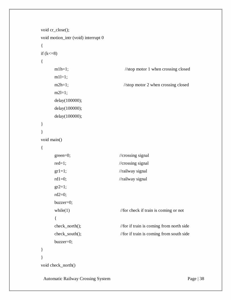
void cr_close();
void motion_intr (void) interrupt 0
{
if (k<=8)
{
m1h=1; //stop motor 1 when crossing closed
m1l=1;
m2h=1; //stop motor 2 when crossing closed
m2l=1;
delay(100000);
delay(100000);
delay(100000);
}
}
void main()
{
green=0; //crossing signal
red=1; //crossing signal
gr1=1; //railway signal
rd1=0; //railway signal
gr2=1;
rd2=0;
buzzer=0;
while(1) //for check if train is coming or not
{
check_north(); //for if train is coming from north side
check_south(); //for if train is coming from south side
buzzer=0;
}
}
void check_north()

Automatic Railway Crossing System Page | 39
{
if (s1==0) //check if train coming from north side if it
is coming than it sense and start to close
crossing
{
green=1;
red=0;
direction='n'; //training is coming from north
cr_close();
while(s3!=0); //wait for 1st railway coach if it will pass
so it will do nothing
while(s3!=1);
while(s3!=0); //wait for last guard if it will pass away
than crossing will open
cr_open();
green=0;
red=1;
while(s4!=0); //if 1st coach will pass from south sensor
then it will interrupted and will not order
to close crossing
while(s4!=1);
while(s4!=0); //same as previous but for last guard
while(s4!=1); // gaurd gone
buzzer=1;
delay(20000);
buzzer=0;
}
else
{
}
}

Automatic Railway Crossing System Page | 40
void check_south()
{
if(s4==0) //check if train coming from south side if it
coming than it sense and start to close crossing
{
green=1;
red=0;
direction='s';
cr_close();
while(s2!=0); //wait for 1st railway coach if it will pass so it
will do nothing
while(s2!=1);
while(s2!=0); //wait for last guard if it will pass away than
crossing will open
cr_open();
green=0;
red=1;
while(s1!=0); //if 1st coach will pass from south sensor
then it will interrupted and will not order
to close crossing
while(s1!=1);
while(s1!=0); //same as previous but for last guard
while(s1!=1);
buzzer=1;
delay(20000);
buzzer=0;
}
else
{
}
}
Automatic Railway Crossing System Page | 41
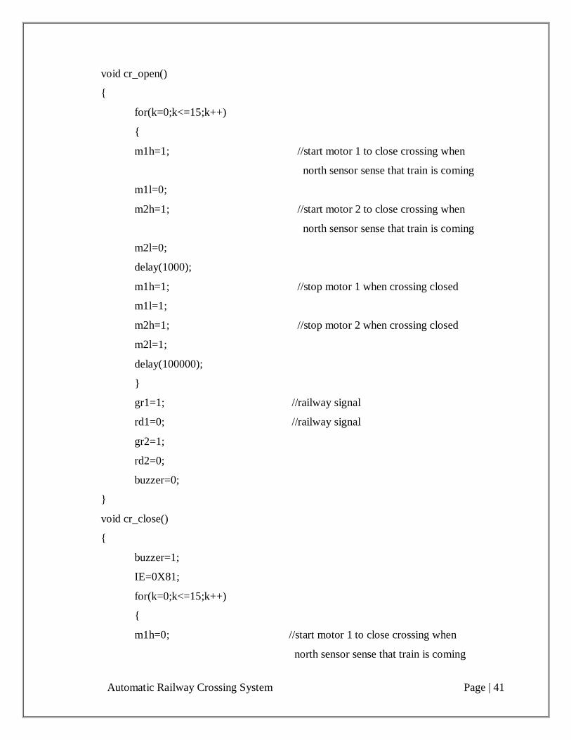
void cr_open()
{
for(k=0;k<=15;k++)
{
m1h=1; //start motor 1 to close crossing when
north sensor sense that train is coming
m1l=0;
m2h=1; //start motor 2 to close crossing when
north sensor sense that train is coming
m2l=0;
delay(1000);
m1h=1; //stop motor 1 when crossing closed
m1l=1;
m2h=1; //stop motor 2 when crossing closed
m2l=1;
delay(100000);
}
gr1=1; //railway signal
rd1=0; //railway signal
gr2=1;
rd2=0;
buzzer=0;
}
void cr_close()
{
buzzer=1;
IE=0X81;
for(k=0;k<=15;k++)
{
m1h=0; //start motor 1 to close crossing when
north sensor sense that train is coming
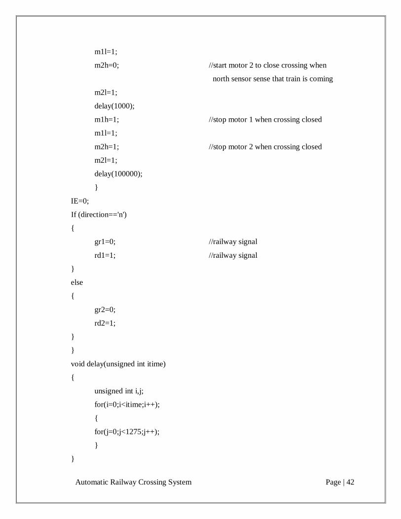
Automatic Railway Crossing System Page | 42
m1l=1;
m2h=0; //start motor 2 to close crossing when
north sensor sense that train is coming
m2l=1;
delay(1000);
m1h=1; //stop motor 1 when crossing closed
m1l=1;
m2h=1; //stop motor 2 when crossing closed
m2l=1;
delay(100000);
}
IE=0;
If (direction=='n')
{
gr1=0; //railway signal
rd1=1; //railway signal
}
else
{
gr2=0;
rd2=1;
}
}
void delay(unsigned int itime)
{
unsigned int i,j;
for(i=0;i<itime;i++);
{
for(j=0;j<1275;j++);
}
}
Automatic Railway Crossing System Page | 43
APPENDIX B: PHOTOGRAPHS OF HARDWARE
Main circuit of hardware (Microcontroller unit):-
Automatic Railway Crossing System Page | 44
Sensor control circuit
Automatic Railway Crossing System Page | 45
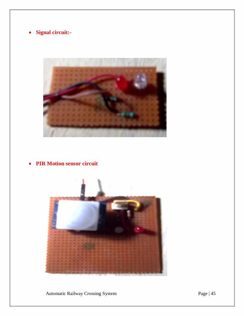
Signal circuit:-
PIR Motion sensor circuit

Automatic Railway Crossing System Page | 46
Complete model circuit
Automatic Railway Crossing System Page | 47
REFERENCES
Following are some internet sites, books, magazines taken as reference for this project:
1. http://www.scribd.com/doc/6852743/AUTOMATIC-RAILWAY-GATE-CONTROL
2. http://sdl-forum.org/SAM_contest/Li_Probert_Williams/Railway_doc.pdf
3. http://indianengineer.wordpress.com/2009/08/03/automatic-railway-gate-control-track-
switching/
4. http://www.nskelectronics.com/files/pirsensor-v11.pdf
5. http://www.keil.com/dd/docs/datashts/atmel/at89s52_ds.pdf
6. www.electronicstutotials.com/oscillators/crystal- oscillators.htm
Books:
1. Muhammad ali mazidi and robin D Mickinlay, “The 8051 microcontroller and embedded
system using assembly and c” Pearson Eduction