automatic pet feeder project proposal and design review
TRANSCRIPT

Automatic Pet Feeder
Project Proposal and Design Review
TA: Henry Duwe
Project Contributions:
Zhuokai Zhao zzhao33 Ziyun He ziyunhe2 Fan Ling fanling2
February 29, 2016

Table of Contents
1. Introduction ………………………………..………………….…………………………..2
1.1. Motivation ………………………….………………….……………..…………...2 1.2. Objectives …………………………………………….……....…………..……....2
2. Design …….….……………………………..……………………………...……………..3
2.1. Block Diagrams …………………….……………………………….…………....3 2.2. Block Description ………………….…………………………………….....…….4
2.2.1. Control Module ……………....…………….…………………..………....4 2.2.2. RFID Module ..…………..….…......………………...…………………....5 2.2.3. Sensor Module…………………….. ....…....……………………………..5 2.2.4. Motor Module …....…...………………………………………....…….….6 2.2.5. Bluetooth/Software Module…….………………..………………………..7 2.2.6. Power Supply Module………….....…....……..……….………………….8
3. Calculation and Simulation …………………..…………………………….....………….8 3.1. Block Diagram…………………….…………………….…………….….……….8 3.2. Block Description…………………….…………………….………….……….…9 3.3. Current range of the zener diode rectifier…………………….…………...………9 3.4. Determine Rs and Filter Capacitance…………………….………………....…….9 3.5. Simulation…………………….…………………….………………..…….…….10
4. Requirement and verification Table...………………………………………....................11 5. Tolerance and analysis………………………………………...…………..…....………..13
6. Cost and schedule……………………………………………...………………...……....13
6.1. Cost……………………………………………...…………………………....….13 6.2. Schedule…...…..…………………………………………....…………………....14
7. Safety and Ethics Statement……………………………………………………………...16 7.1. Safety…………………………………………………………………………….16
7.1.1. Electrical concerns…….………..….……..……...………………….…...16 7.1.2. Mechanical concerns……….…………….....……………………….…...16
7.2. Ethics….………….………….………….………….………….………….…...…16
1

1. Introduction We chose this project because pet keeping is a time consuming responsibility and we
want to provide convenience to owners by helping them feed their pets easily and smartly. 1.1. Motivation
Keeping pets takes many commitments. This includes keeping them company, showing your concerns and of course, feeding them on time and in the correct way. However, not everyone is a pet expert, taking care of your pet’s diet can be hard and time consuming. One of the top health concerns of pets are overeating and obesity. Especially at younger age, they are usually satisfied with whatever much is given to them. Many adult pets are also fed unscientifically that later may cause short lifespan. Another problem of feeding pets is that owners might not always be home regularly. Being occupied by personal plans knowing that they still have a starving little fellow at home to be taken care of is always a concern that bothers owners. The third concern that we want to deal with is the fact that there hasn’t been any product on the market right now that is able to dispense different foods for different kinds of pets. However, pets themselves might not necessarily recognize the potential health problems of eating the wrong food. Therefore, we want to take care of owners’ concern of feeding by building a phonecontrolled automatic pet feeder that can dispense the correct amount of food on time, based on the type of animal that’s demanding it. 1.2. Objectives
Our project is designed to help all the pet owners to feed their pets remotely and smartly. Benefits to customer:
● Customers do not have to worry about their pets during business trips or vacations. ● Customers can now know better about their pet’s health condition by monitoring exactly
how much food they eat everyday. ● Customers can now feed different kind of pets with ease. They no longer need to worry
about their dog eating their cat’s food or vice versa. Product feature:
● The phone app could set the correct amount of food to drop at the correct time. ● The phone app could save a pet profile (name, age, birthday, weights, etc) for owners to
keep track. ● The app could keep track of how much food the pets have consumed in a long run
graphically. ● The machine could be sustained by both power cords. ● RFID will be embedded into pets’ tags to differentiate types of pets for different food
needs.
2

2. Design 2.1. Block Diagram
Figure 1: General block diagram of the hardware design
3

Figure 2: Flowchart of the software design
2.2. Block Descriptions
2.2.1. Control Module Input: 3.3V power supply, ASCII signal from RFID module through UART, Digital
signal from load cell through GPIO, Data received from Bluetooth Module. Output: PMW after level shift to Motor, Data transfer to Bluetooth Module.
The purpose of the control module is to receive input signals from sensors and RFID and
send instructions to motor and transfer data with Bluetooth module. The PCB which consists of a Texas Instrument 16bit microcontroller MSP430F2274, a 256 kB flash storage and 1kB RAM. It will process the inputs and send different instruction to other module in different situations. First, when RFID detects the tag at the set feeding time, it will check if the current exposed region of the food plate belongs to the particular pet. If it is true, microcontroller will send pulse signal to servo motor and start dispensing food. If it is false, microcontroller will send pulse signal to servo motor and rotate the food plate to the right position before dispensing. Second, when the weight module measures insufficient amount of food at feeding time, the microcontroller will send signals to dispense more food. Until the weight module sends back the the signal that weight has already reached the set value, microcontroller will stop the servo
4

motor. Third, when there is no sufficient food left in the container (less than the weight of one meal), microcontroller will send signals to the bluetooth module which will send alert to the software in order to warn users to refill. In addition, the microcontroller will store pet’s food consumption data and send it to the software upon Bluetooth request.
2.2.2. RFID Module Input: 3.3V power supply, 125kHz RF tag Output: ASCII to Microcontroller through UART
RFID module is used to recognize different kind of pets. It consists of two separate parts:
ID12LA RFID Reader and the passive RFID tags, which will be attached to the pet’s bracelets. ID12LA is a high frequency RFID reader, it provides around 30 cm range for detection after antenna. Once the pet steps within the range of detection, the reader will be notified and send a signal high to the microcontroller.
Figure 3: ID12LA RFID Module
2.2.3. Sensor Module Input: 3.3V power supply, Analog signal from strain gauge Output: Digital signal to Microcontroller through GPIO
Sensor module is used to measure the weights of the food containers and the food plates.
It consists of two parts: load cells and load cell module. They are used to measure the food
5

weight in the food containers and on the food plates. The range of each load cell is 05Kg, which is sufficient for our design since the food in the container will not exceed 5kg. Each load cell is connected to a SparkFun HX711 Load Cell Module. The 24bit analog to digital converter in the Module will convert the signal to digital so it can be processed by the microcontroller.
Four load cells are used in four various locations. Two of them are put beneath the two identical cylindrical containers. The other two load cells are attached to the bottom of each separate food plate in the shape of a halfcircle. They will keep track the weight of the food the pet has consumed. All the four load cells will be taking measurements constantly and sending their data to the microcontroller.
[2] Figure 4: HX711 Load Cell Module
2.2.4. Motor Module Input: 5V PWM from microcontroller Output: Mechanical rotation
Motor Module is used to physically drive the gates for food containers as well as food
plates. Two MG995 High Speed Metal Gear Dual Ball Bearing Servo Motors are used in our project. Microcontroller will send precoded PWM to control the servomotor. One motor will control the gate of the food container, and execute the dispensing order by spinning the gate plate to a desired location. The gate is a circular shape plate attached in the middle of the two
6
containers with a 120° opening on it. There will also be a 120° pie shape opening on the bottom of each food container, which is the same size corresponding to the 120° pie shape opening on the gate plate. This allows the food to be dispensed when the two pie shapes overlap with each other.
The other servomotor controls the plate by the specified angle and direction to expose the corresponding half of the plate for the particular pet. The food plate will be a half closed structure where only one side of the food plate would be exposed at a time.
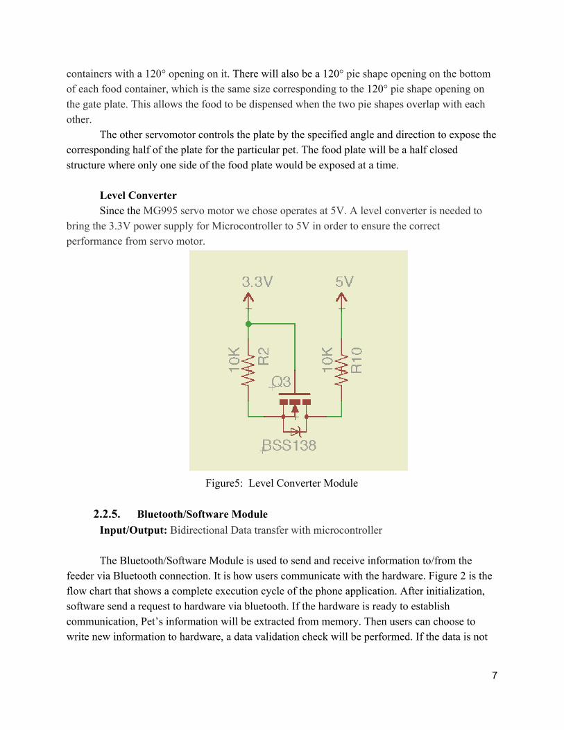
Level Converter Since the MG995 servo motor we chose operates at 5V. A level converter is needed to
bring the 3.3V power supply for Microcontroller to 5V in order to ensure the correct performance from servo motor.
Figure5: Level Converter Module
2.2.5. Bluetooth/Software Module Input/Output: Bidirectional Data transfer with microcontroller The Bluetooth/Software Module is used to send and receive information to/from the
feeder via Bluetooth connection. It is how users communicate with the hardware. Figure 2 is the flow chart that shows a complete execution cycle of the phone application. After initialization, software send a request to hardware via bluetooth. If the hardware is ready to establish communication, Pet’s information will be extracted from memory. Then users can choose to write new information to hardware, a data validation check will be performed. If the data is not
7

valid software will send back a rejection signal to hardware and tell it to reload information. Otherwise the information will be displayed on software and the instruction is complete.
Bluetooth will be implemented by RN42 Bluetooth Module. RN42 is a module for a short range (5060 feet) application. It can be connected directly to the MSP430F2274 Microcontroller.
2.2.6. Power Supply Module Input: 120V from household voltage supply Output: 3.3/5V power supply
The power supply module is used to give power supply to all the components in our
project. It converts the 120V AC voltage to the 5V DC voltage. The detailed implementation is enclosed in the section below. 3. Calculation and Simulation with Power Supply
3.1. Block Diagram
[4] Figure 6: Block Diagram
3.2. Block Description From the circuit diagram above, it could be easily seen that the voltage was changed from
120V RMS to 6V RMS by a transformer with N2/N1 = 1/20. The diode rectifier is a fullwave rectifier shown below.
8

Figure 7: Fullwave rectifier schematic
The capacitive filter reduces the ripple peaktopeak voltage since it resists changes in
voltage. The output becomes much smoother after the filter. The last component is the voltage regulator, which consists of a zener diode in its breakdown region. It acts like a voltage regulator because at breakdown region, the voltage across the zener diode is always 5V.
3.3. Current range of the zener diode rectifier Zener Diode 1N4733A was used in the circuit. Imin = 17.5 mA. The maximum value of
diode current was decided by two factors the output current and the maximum allowed power dissipation of the zener diode. When there is no load connected to the regulator, Imax = Imin + 20 mA. However, there must be a limit that the zener diode can handle. The maximum current cannot grow unlimitedly as the minimum current increases. It turns that the maximum current allowed is regulated by the maximum power of the zener diode, which is 500mW. Since the real power should not exceed the 75% of the maximum allowed power, Pmax = 375 mW, which makes the Imax = 37.5 mA.
Figure 8: Circuit Schematic
9

3.4. Determine Rs and Filter Capacitance After determining the maximum and minimum current of the zener diode rectifier, the
value of Rs was found. The diagram below is used to show the circuit for determining ripple voltage across the capacitor.
Figure 9: Filter schematic
Since the ripple voltage is required to be less than 2%, it should be less than 0.2. After
applying KVL to circuit, following equations were obtained:
Capacitance for fullwave rectifier were obtained separately as shown below:
3.5. Simulation Simulation was conducted on the circuit design through the PSPICE. Output DC voltage
was measured and plotted as shown in the graph below. It is clear that the power supply has a fast rising time which is almost instantly and a quick stabilizing time which is around 0.05s.
10

Figure 10: The average output DC voltage of 120sqrt(2) VSIN without load
4. Requirement and Verification Module Requirement Verification Points
RFID Module a. Be able to recognize the pets correctly in the range of 30 cm +/ 5 cm. Module is implemented with a LED as an indicator
a) 1. Test the RFID module by placing the tag at
20cm, 30cm, 40cm, away from the receiver. 2. Check the functionality of the RFID module by
monitoring the LED. If the LED is on only at 20cm and 30cm the functionality of the module is correct.
20 points
Sensors Module a. Be able to measure the weight from 10 gram to 2000 gram.
b. Be able to respond to the change of weights in food containers
a) 1. Straingauge load cells will convert the load
acting on them into electrical signals. Functionality of the module can be tested by measuring the output voltage.
2. Put 10 gram and 2000 gram food on the plate and measure the output voltage.
3. The module’s electrical resistance changes in proportion to the load. Information in the datasheet and recorded voltage can be used to calculate measured force in order to ensure functionality.
b) 1. Gradually pour food into the container from 10
gram to 2000 gram.
25 points
11

2. Monitor the output voltage to see if there is any discontinuity or unusuality.
Motor Module a. Be able to rotate by 120 degree and 180 degree in clockwise/counterclockwise directions and hold.
b. Steady performance
a) 1. Connect the module to a arduino first because
the Motor module contains two digital servo motors that are compatible with arduino.
2. Send 120/180 degrees and clockwise/counterclockwise direction to the input of the module from test code.
3. Check if the motor perform the corresponding instruction and hold.
b) 1. Perform test a) 10 times 2. Check if the motor is experiencing any drift by
comparing the angle from beginning and end.
20 points
Control Module a. When mounted to PCB, microcontroller should be able to program the Bluetooth module to transmit data to the software.
b. When mounted to PCB,
microcontroller should be able program the Bluetooth module to receive data from software. LED indicator will be implemented on the PCB
c. Check if the latency is within the range of the standard bluetooth latency 150ms (+/50ms)
a) 1. Connect the Module to PCB. 2. Run the test code onto microcontroller via
Arduino. 3. Check if the data is received by the software.
b)
1. Connect the Module to PCB. 2. Send test signal from software to
microcontroller 3. Check if the LED is on.
c)
1. Connect the Module to PCB. 2. Run a single instruction in a for loop containing
100 cycles. 3. Record the time and divide it by 100 to get the
latency per cycle and compare the result to the standard value.
20 points
Power Module
a. Supply 5V +/0.25V and 3.3V +/0.25V at a minimum of 1A +/ 0.25A
a) 1. Place Digital Multimeter in parallel with the
power source. Measure the voltage difference across the power source. The voltage should read 5V +/ 0.25V around Motor and 3.3V +/0.25V around other component.
2. Place Digital Multimeter in series with the
power source and heating elements. Measure the current difference from the power source. The current should read 1A +/ 0.25A
15 points
12

5. Tolerance Analysis In terms of our project, the high level goal is to make two pets to be fed by the right food
in the correct amount. More specifically, for every time the food is dispensed, 100g of food should be released. The maximum tolerance allowed is +/ 10g so we are able to keep track of pets’ food consumption in a more accurate way. The tolerance was set as 15g because it is the weight that approximately equals to 10 pieces of dog/cat food. Due to the physical limits of the gate, it is reasonable to have 5 pieces more/less dog/cat food during the opening/closing of the gate. Among all components, bluetooth latency will not have significant effect because it should not happen at the time of dispensing. The accuracy of the servomotor at the gate of the dispense does not have a huge impact on our high level goal. This is because the amount of food dispensed is controlled by the weight sensors so that it will still be able to dispense the right amount, although the off of angle might cause the dispensing process to be not as smooth.
On the other hand, the weight sensors we will be using, which consist of load cells and AD modules, are the most essential part of our project, because we want to make sure that the correct amount of food is dispensed so that we can obtain the accurate information of each pet. The load cells we are going to use will have a range from 05 kg. To test the tolerance of the sensor, we will be loading different amount of food onto the plate and check its accuracy compared to the actual one. Though normally the food container will not be big enough to hold 5 kg, it is still important to test its extremes cases. To perform the test, we will put food of exactly or slightly over than 5 kg on the load cell and see if it’s measuring correctly. The results will be recorded in the notebook.
6. Cost and Schedule 6.1. Cost
Labor: Zhuokai Zhao: $40/hour * 2.5 * 150 hours = $15,000 Ziyun He: $40/hour * 2.5 * 150 hours = $15,000 Fan Ling: $40/hour * 2.5 * 150 hours = $15,000 Total: $45,000 Parts List:
1. Four HX711 Load Cell Weighing Sensor AD Module ($9 each) 2. Four Load Cell Sensor 05 kg ($6 each) 3. Two MG995 High Speed Metal Gear Dual Ball Bearing Servo ($14.36 each)
13

4. Two RFID Module ($8.99 each) 5. Two Buckets for Food Container and Outside Cone Shape ($4+$8) 6. RN42 Wireless Bluetooth Transceiver Module($5.99)
Sum planned parts cost: $118.71 Grand Total: $15,118.71 6.2. Schedule Week Task Responsibility
February 8 Finish Project Proposal Prepare for Mock Design Interview
Ziyun He
Finish Project Proposal Prepare for Mock Design Interview
Fan Ling
Finish Project Proposal Prepare for Mock Design Interview
Zhuokai Zhao
February 15 Complete the Eagle Assignment Consult Experts
Ziyun He
Complete the Eagle Assignment Consult Experts
Fan Ling
Complete the Eagle Assignment Select and Acquire Equipment, such as Servo, Weight Sensors, RFID, and Bluetooth Module
Zhuokai Zhao
February 22 Build “Profile” Tab for Phone App Ziyun He
Build and Test the Power Module Fan Ling
Prepare for Design Review Design and Acquire PCB
Zhuokai Zhao
February 29 Build “Setting” Tab for Phone App Design and Acquire PCB
Ziyun He
Build and Test the Power Module Test and Find the Right Spin Speed for Both Servomotors
Fan Ling
Design and Acquire PCB Zhuokai Zhao
March 7 Build “Setting” Tab for Phone App Design and Acquire PCB
Ziyun He
Test and Find the Right Spin Speed for Both Servomotors Test the Weight Sensors and Obtain Their Limits
Fan Ling
14
Design and Acquire PCB Build and Test RFID Module
Zhuokai Zhao
March 14 Build “Data” Tab for Phone App Build the Outside Supporting Structure, Gates, Food Plates, Dividers and Containers
Ziyun He
Test the Weight Sensors and Obtain Their Limits Build the Outside Supporting Structure, Gates, Food Plates, Dividers and Containers
Fan Ling
Build and Test RFID Module Finalize Design for PCB
Zhuokai Zhao
March 21 Build “Data” Tab for Phone App Build the Outside Supporting Structure, Gates, Food Plates, Dividers and Containers
Ziyun He
Build and Test Bluetooth Module Test Sensor and Servo with PCB
Fan Ling
Build and Test Bluetooth Module Zhuokai Zhao
March 28 Test App Functionalities with PCB Ziyun He
Test Sensor and Servo with PCB Fan Ling
Test Bluetooth and RFID Modules with PCB Zhuokai Zhao
April 4 Finalize R&V Table Prepare for Mock Demo/Debug
Ziyun He
Prepare for Mock Demo Finalize PCB
Fan Ling
Finalize R&V Table Prepare for Mock Demo
Zhuokai Zhao
April 11 Testing and Debugging App Functionality with PCB Prepare for Mock Presentation
Ziyun He
Testing and Debugging Sensor and Servomotors Prepare for Demo
Fan Ling
Testing and Debugging RFID and Bluetooth Module Prepare for Demo
Zhuokai Zhao
April 18 Corner cases and Optimization with App Prepare for Mock Presentation
Ziyun He
Corner cases and Optimization with Sensors and Servomotors Prepare for Mock Presentation
Fan Ling
Corner cases and Optimization with RFID and Bluetooth Module Zhuokai Zhao
15

Prepare for Demo
April 25 Complete Final Paper Prepare for Presentation
Ziyun He
Final Paper Prepare for Presentation
Fan Ling
Final Paper Prepare for Presentation
Zhuokai Zhao
May 2 Finalize Final Paper Ziyun He
Finalize Final Paper Fan Ling
Finalize Final Paper Zhuokai Zhao
7. Safety and Ethics Statement
7.1. Safety
7.1.1. Electrical Concerns: The product is powered by standard power outlet of 120V through a power cord and
protected by plastic wrapping around the metal wire. If the power line is exposed to air, users should not contact the power cord directly. Instead they should turn the power off immediately and rewrap and protect the wires before any harm coming to them or their pets.
Do not place the machine in extreme heat conditions. Temperature over 70°C is extremely dangerous for microcontrollers and power system.
7.1.2. Mechanical concerns: Two servomotors are used in our product. If the exterior of the product is compromised in
anyway, please replace the product immediately to prevent any injury may come to you and your pets. In particular, when the food plate is spinning to the right section of the pet food, although we have polished the structure to prevent people/pet from accidentally getting stuck in between the spinning process, please still pay attention to the machine when it spins.
7.2. Ethics The IEEE Code of Ethics [2] was used to guide the ethical considerations of this project
1. The Automated Pet Feeder is a pet friendly product that provide customers’ pets a
safe and healthy environment to feed. Pet’s safety is always the top concern during the production.
16

2. The Automated Pet Feeder will always dispense the correct amount of food within the tolerance. This will be ensured by rigorous experiment and test before our product is being used.
3. Shortcuts in implementation will not be used at the expense of the eventual users of the product.
4. Performance of the Automated Pet Feeder will be based off the available data with honesty and relisticicty.
5. All motivation behind this project is from sheer interest of producing a novel useable product. Any other forms of motivation, including bribery, will not be used to alter our desired end goal.
17

References
[1] "Atmel AVR 8bit and 32bit Microcontrollers." Atmel AVR 8bit and 32bit Microcontrollers. N.p., n.d. Web. 18 Feb. 2016. http://www.atmel.com/products/microcontrollers/avr/ [2] 24Bit AnalogtoDigital Converter (ADC) for Weigh ScalesHX711 Retrieved March 01, 2016, from https://cdn.sparkfun.com/datasheets/Sensors/ForceFlex/hx711_english.pdf [3] MG995 High Speed Metal Gear Dual Ball Bearing Servo Retrieved March 01, 2016, from http://www.electronicoscaldas.com/datasheet/MG995_TowerPro.pdf [4] Sedra, Adel S., and Kenneth C. Smith. Microelectronic Circuits. N.p.: n.p., n.d. Print. [5] IEEE IEEE Code of Ethics. (n.d.). Retrieved February 29, 2016, from http://www.ieee.org/about/corporate/governance/p78.html [6] MSP430F2274 (ACTIVE). (n.d.). Retrieved March 01, 2016, from http://www.ti.com/product/MSP430F2274 [7] RN42 Wireless Bluetooth Transceiver Retrieved March 01, 2016, from https://www.sparkfun.com/datasheets/Wireless/Bluetooth/rn42ds.pdf
18

Appendix A:
Control RFID Load Cell Motor Bluetooth
Part Number
MSP430F2272 ID12LA HX711 MG995 RN42
Input 3.3V power supply, ASCII from RFID, Digital signal from load cell
3.3V power supply, 125kHz tag in range
3.3V power supply, Analog signal from strain gauge
5V PWM from microcontroller
Bidirectional Data transfer with microcontroller
Output PMW after level shift to Motor,
ASCII to Microcontroller through UART
Digital signal to Microcontroller through GPIO
Mechanical rotation
Bidirectional Data transfer with microcontroller
Operation voltage
1.8V3.3V 2.8V5V 2.7V5V 4.8V7.2V 3.0V3.6V
Operation Current
270 µA at 1 MHz, 2.2 V
<5mA <1.5mA N/A <50mA
Output Data rate
N/A 10SPS or 80SPS 8.5 kgf∙cm (4.8 V ), 10 kgf∙cm (6 V)
240Kbps (slave), 300Kbps (master)
19