automatic control gate railway gategnu.inflibnet.ac.in/bitstream/123456789/1568/1/automatic...
TRANSCRIPT
Automatic Railway Gate Control System
Page 1
GUJARAT TECHNOLOGICAL UNIVERSITY
UDP-I
(USER DEFINED PROBLEM)
AAUUTTOOMMAATTIICC CCOONNTTRROOLL GGAATTEE
RRAAIILLWWAAYY GGAATTEE
BRANCH: MECHATRONICS
SEMESTER: 5TH
BATCH NO: 05
B.S.PATEL.POLYTECHNIC, KHERVA (Affiliated to Gujarat Technological University)
Automatic Railway Gate Control System
Page 2
Certificate
This to certify that project entitled “AUTOMATIC CONTROLLED
RAILWAY CROSSING STYSTEM”. Submitted in partial fulfillment
of the requirement for the award of DIPLOMA ENGINEERING under
four wall of B.S. PATEL POLYTECNIC is faithfully record of the
bonafide project work,
The following candidate under my guidance & supervision.
1. SHAH HARDIK 106440320034
2. PANCHAL JAY 106440320001
3. KAPADIYA PARTH 106440320040
4. PANCHAL MITESH 096440320050
5. MISTRY UTSAV 086440320018
MR. K.P.PATEL MR. V.K.PATEL
(H.O.D MECHATRONICS) (INTERNAL GUIDE)

Automatic Railway Gate Control System
Page 3
Acknowledgement
We are acknowledge my indebtedness and convey my sincere thanks to our
Project Guide MR.V.K.PATEL, faculty of Mechatronics, B.S.PATEL
POLTYTECNIC. Who sincerely helped us to giving inspiration, new ideas and
infrastructure throughout the semester. I would also like to thanks
mechatronics department of B.S.P.P to give us such platform for making this
project successfully. I also convey my thanks to the faculty of our collage &
our group member who have helped entirely. At last, I again convey my
special thanks to project guide, who decided to shows the model of the project
at the workshop arranged at the time.
Automatic Railway Gate Control System
Page 4
INDEX
Sr.no. Content
page
no.
CH:1 Introduction of automated railway gate system
1.1 Introduction
1.2 Abstract
1.3 Working methodology
1.4 Gate control system
CH:2 Hardware of automated railway crossing system
2.1 Microcontroller
2.1.1 Atmel 89c51 microcontroller description
2.2 Stepper motor
2.2.1 Constructions
2.3 Components
2.3.1 Capacitor
2.3.2 Resistor
2.3.3 Power supply
2.4 Sensor
2.4.1 IR transistor
2.4.2 IR receiver
2.5 Flexible wire
CH:3
Software system of automated railway crossing
system

Automatic Railway Gate Control System
Page 5
USER DEFINED PROBLEM/PROJECT STATEMENT FORM
STUDENT PARTICULARS
STUDENT NAME: - SHAH HARDIK.S
ENROLLMENT NO.:-106440320034
MOBILE NO.:-8866475115
COLLAGE NAME:-B.S.PATEL POLYTECNIC, GANPAT UNIVERSITY
BRANCH:-MECHATRONICS
SEMESTER:-5TH
STUDENT NAME: - PANCHAL JAY.K
ENROLLMENT NO.:-106440320001
MOBILE NO.:-8511060032
COLLAGE NAME:-B.S.PATEL POLYTECNIC, GANPAT UNIVERSITY
BRANCH:-MECHATRONICS
SEMESTER:-5TH
STUDENT NAME: - PANCHAL MITESH.D
ENROLLMENT NO.:-096440320067
MOBILE NO.:-8000369967
COLLAGE NAME:-B.S.PATEL POLYTECNIC, GANPAT UNIVERSITY
BRANCH:-MECHATRONICS
SEMESTER:-5TH
STUDENT NAME: - KAPADIYA PARTH K.
ENROLLMENT NO.:-106440320040
MOBILE NO.:-9737602148
COLLAGE NAME:-B.S.PATEL POLYTECNIC, GANPAT UNIVERSITY
BRANCH:-MECHATRONICS
SEMESTER:-5TH

Automatic Railway Gate Control System
Page 6
STUDENT NAME: - MISTRY UTSAV.B
ENROLLMENT NO.:-086440320018
MOBILE NO.:-8866719958
COLLAGE NAME:-B.S.PATEL POLYTECNIC, GANPAT UNIVERSITY
BRANCH:-MECHATRONICS
SEMESTER:-5TH
Automatic Railway Gate Control System
Page 7
Chapter: 1 Introduction of automated railway
crossing system
Chapter: 1
Automatic Railway Gate Control System
Page 8
Introduction of automated railway crossing system.
The objective of this project is to manage the control system of railway gate
using the microcontroller. When train arrives at the sensing point alarm is
triggered at the railway crossing point so that the people get intimation that
gate is going to be closed. Then the control system activates and closes the
gate on either side of the track once the train crosses the other end control
system automatically lifts the gate. For mechanical operation of the gates 1.8
step angle stepper motors are employed. Here we are using embedded
controller built around the 8051 family (AT89C52) for the control according to
the data pattern produced at the input port of the micro controller, the
appropriate selected action will be taken. The logic is produced by the
program written in Embedded C language. The software program is written,
by using the KEIL micro vision environment. The program written is then
converted in HEX code after simulation and burned on to microcontroller
using FLASH micro vision.
The objective of this project is to manage the control system of railway gate
using the microcontroller. When train arrives at the sensing point alarm is
triggered at the railway crossing point so that the people get intimation that
gate is going to be closed. Then the control system activates and closes the
gate on either side of the track. Once the train crosses the other end control
system automatically lifts the gate. For mechanical operation of the gates 1.8
step angle stepper motors are employed. Here we are using embedded
controller built around the 8051 family (AT89C52) for the control according to
the data pattern produced at the input port of the micro controller, the
appropriate selected action will be taken. The logic is produced by the
program written in embedded Keil-C language. The software program is
written, by using the KEIL micro vision environment. The program written is
then converted in HEX code after simulation and burned on to
microcontroller using FLASH micro vision.
1.1 Abstract
Automatic Railway Gate Control System
Page 9
The objective of this project is to provide an automatic railway gate at a level
crossing replacing the gates operated by the gatekeeper. It deals with two
things. Firstly, it deals with the reduction of time for which the gate is being
kept closed. And secondly, to provide safety to the road users by reducing the
accidents.
By the presently existing system once the train leaves the station, the
stationmaster informs the gatekeeper about the arrival of the train through
the telephone. Once the gatekeeper receives the information, he closes the
gate depending on the timing at which the train arrives. Hence, if the train is
late due to certain reasons, then gate remain closed for a long time causing
traffic near the gates.
By employing the automatic railway gate control at the level crossing the
arrival of the train is detected by the sensor placed near to the gate. Hence, the
time for which it is closed is less compared to the manually operated gates
and also reduces the human labor. This type of gates can be employed in an
unmanned level crossing where the chances of accidents are higher and
reliable operation is required. Since, the operation is automatic; error due to
manual operation is prevented.
Automatic railway gate control is highly economical microcontroller based
arrangement, designed for use in almost all the unmanned level crossings in
the country.
1.2 Working methodology
Present project is designed using 8051 microcontroller to avoid railway
accidents happening at unattended railway gates, if implemented in spirit.
This project utilizes two powerful IR transmitters and two receivers; one pair
of transmitter and receiver is fixed at upside (from where the train comes) at a
level higher than a human being in exact alignment and similarly the other
pair is fixed at down side of the train direction. Sensor activation time is so
adjusted by calculating the time taken at a certain speed to cross at least one
compartment of standard minimum size of the Indian railway. We have
Automatic Railway Gate Control System
Page 10
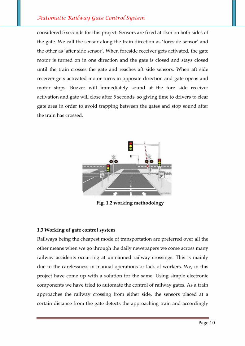
considered 5 seconds for this project. Sensors are fixed at 1km on both sides of
the gate. We call the sensor along the train direction as ‘foreside sensor’ and
the other as ‘after side sensor’. When foreside receiver gets activated, the gate
motor is turned on in one direction and the gate is closed and stays closed
until the train crosses the gate and reaches aft side sensors. When aft side
receiver gets activated motor turns in opposite direction and gate opens and
motor stops. Buzzer will immediately sound at the fore side receiver
activation and gate will close after 5 seconds, so giving time to drivers to clear
gate area in order to avoid trapping between the gates and stop sound after
the train has crossed.
Fig. 1.2 working methodology
1.3 Working of gate control system
Railways being the cheapest mode of transportation are preferred over all the
other means when we go through the daily newspapers we come across many
railway accidents occurring at unmanned railway crossings. This is mainly
due to the carelessness in manual operations or lack of workers. We, in this
project have come up with a solution for the same. Using simple electronic
components we have tried to automate the control of railway gates. As a train
approaches the railway crossing from either side, the sensors placed at a
certain distance from the gate detects the approaching train and accordingly
Automatic Railway Gate Control System
Page 11
controls the operation of the gate. Also an indicator light has been provided to
alert the motorists about the approaching train.

Automatic Railway Gate Control System
Page 12
Chapter no: 2
Hardware of automated railway crossing
gate
Chapter. 2
Hardware of automated railway crossing gate
Descriptions
Automatic Railway Gate Control System
Page 13
• Microcontroller
• Stepper motor
• Components
• Sensors
• Flexible wire
2.1 Microcontroller
Microcontrollers are "embedded" inside some other device (often a consumer
product) so that they can control the features or actions of the product.
Another name for a microcontroller, therefore, is "embedded controller."
Microcontrollers are dedicated to one task and run one specific program. The
program is stored in ROM (read-only memory) and generally does not
change. Microcontrollers are often low-power devices. A microcontroller has
a dedicated input device and often (but not always) has a small LED or LCD
display for output.
A microcontroller also takes input from the device it is controlling and
controls the device by sending signals to different components in the device.
For example, the microcontroller inside a TV takes input from the remote
control and displays output on the TV screen. The controller controls the
channel selector, the speaker system and certain adjustments on the picture
tube electronics such as tint and brightness. The engine controller in a car
takes input from sensors such as the oxygen and knock sensors and controls
things like fuel mix and spark plug timing. A microwave oven controller
takes input from a keypad, displays output on an LCD display and controls a
relay that turns the microwave generator on and off. A microcontroller is
often small and low cost. The components are chosen to minimize size and to
be as inexpensive as possible. A microcontroller is often, but not always,
ruggedized in some way. On the other hand, a microcontroller embedded
inside a VCR hasn't been ruggedized at all. The actual processor used to
implement a microcontroller can vary widely. The Micro controller
(AT89C51) is a low power; high performance CMOS 8-bit micro controller
Automatic Railway Gate Control System
Page 14
with 4K bytes of Flash programmable and erasable read only memory
(PEROM). The on-chip Flash allows the program memory to be
reprogrammed in-system or by a conventional non-volatile memory
programmer. By combining a versatile 8-bit CPU with Flash on a monolithic
chip, the Atmel AT89C51 is a powerful microcomputer, which provides a
highly flexible and cost-effective solution to many embedded control
applications. By using this controller the data inputs from the smart card is
passed to the parallel port of the pc and accordingly the software responds.
The idea for writing the embedded program using KEIL software.
2.1.1Atmel 89c51 Microcontroller Description:
The AT89C51 is a low-power, high-performance CMOS 8-bit microcomputer
with 4K bytes of Flash programmable and erasable read only memory
(PEROM) based on the famous 8051 architecture. The device is manufactured
using Atmel’s high-density nonvolatile memory technology and is compatible
with the industry-standard MCS-51 instruction set and pin out. The on-chip
Flash allows the program memory to be reprogrammed in-system or by a
conventional nonvolatile memory programmer. By combining a versatile 8-bit
CPU with Flash on a monolithic chip, the Atmel AT89C51 is a powerful
microcomputer which provides a highly-flexible and cost-effective solution to
many embedded control applications.
Features
The AT89C51 provides the following standard features:
• Compatible with MCS-51 Products
• Endurance: 1,000 Write/Erase Cycles
• 4K Bytes of In-System Reprogrammable Flash Memory
• 128 bytes of Internal RAM (128 x 8-bit)
• 32 Programmable I/O Lines
• Two 16-bit Timer/Counters
• Five vector two-level interrupt architecture
Automatic Railway Gate Control System
Page 15
• A full duplex serial port
• Three-level Program Memory Lock
• Six Interrupt Sources
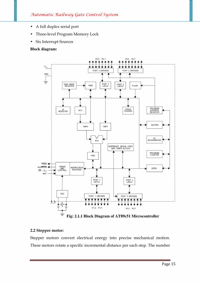
Block diagram:
5.3
Fig: 2.1.1 Block Diagram of AT89c51 Microcontroller
2.2 Stepper motor:
Stepper motors convert electrical energy into precise mechanical motion.
These motors rotate a specific incremental distance per each step. The number

Automatic Railway Gate Control System
Page 16
of steps executed controls the degree of rotation of the motor’s shaft. This
characteristic makes step motors excellent for positioning applications. For
example, a 1.8° step motor executing 100 steps will rotate exactly 180° with
some small amount of non-cumulative error. The speed of step execution
controls the rate of motor rotation. A 1.8° step motor executing steps at a
speed of 200 steps per second will rotate at exactly 1 revolution per second.
Stepper motors can be very accurately controlled in terms of how far and how
fast they will rotate. The number of steps the motor executes is equal to the
number of pulse commands it is given. A step motor will rotate a distance
and at a rate that is proportional to the number and frequency of its pulse
commands.
Basic Stepper Motor System
Fig: 2.2.1 Basic stepper motor system
The diagram above shows a typical step motor based system. All of these
parts must be present in one form or another. Each component’s performance
will have an effect on the others. By altering the frequency of the pulse train,
the pulse generator can instruct the motor to accelerate, run at a speed,
decelerate or stop. A pulse generator must be present otherwise the motor
will not move. Next is the motor driver. The driver takes the pulses from the
pulse generator and determines how and when the windings should be
energized. The windings must be energized in a specific sequence to generate
motion. Finally there is the step motor itself. A step motor has two primary
parts; the rotor, the moving piece, and the stator, the stationary piece. The
stator contains coils of wire called windings. The rotor spins on bearings or
bushings inside the stator. All step motors operate through the principle of
the rotor following a rotating magnetic field created by sequencing the flow of
Automatic Railway Gate Control System
Page 17
current through the stator windings. Each NMB step motor has two phases,
which are groups of electrically connected windings. As current is passed
through each phase, the motor takes “steps” or small movements to keep in
synchronism with the magnetic field. The degree of rotation per step depends
on the style of driver used and the construction of the motor.We have used
hybrid stepper motor because its most suitable for our task.
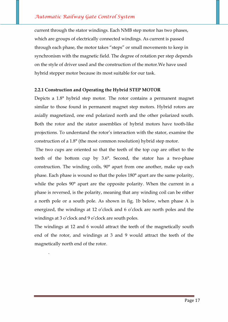
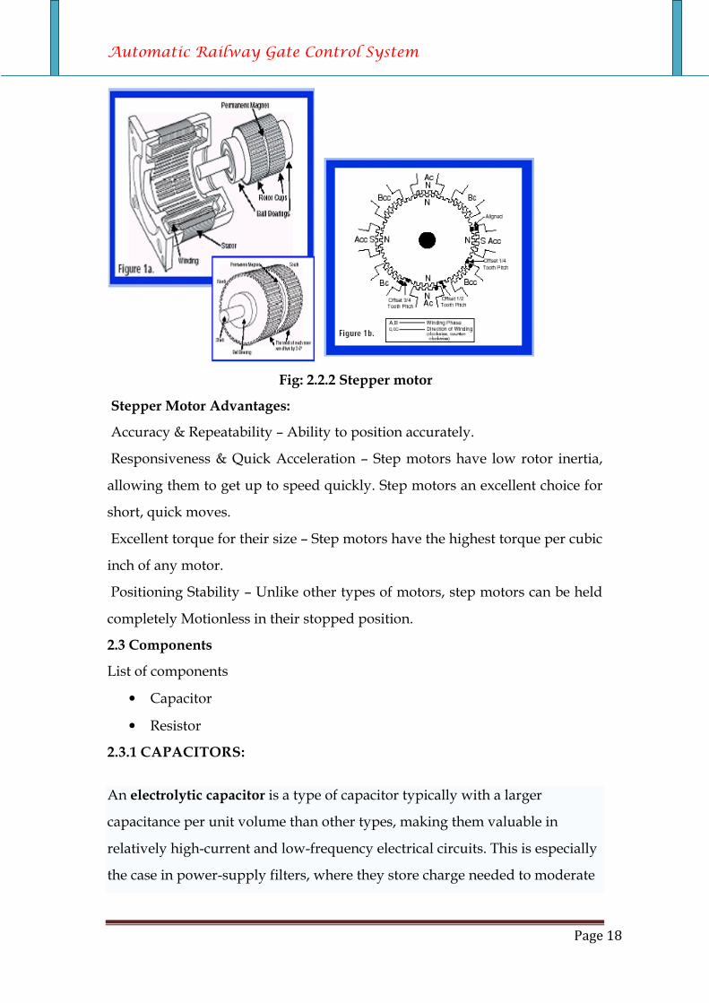
2.2.1 Construction and Operating the Hybrid STEP MOTOR
Depicts a 1.8° hybrid step motor. The rotor contains a permanent magnet
similar to those found in permanent magnet step motors. Hybrid rotors are
axially magnetized, one end polarized north and the other polarized south.
Both the rotor and the stator assemblies of hybrid motors have tooth-like
projections. To understand the rotor’s interaction with the stator, examine the
construction of a 1.8° (the most common resolution) hybrid step motor.
The two cups are oriented so that the teeth of the top cup are offset to the
teeth of the bottom cup by 3.6°. Second, the stator has a two-phase
construction. The winding coils, 90° apart from one another, make up each
phase. Each phase is wound so that the poles 180° apart are the same polarity,
while the poles 90° apart are the opposite polarity. When the current in a
phase is reversed, is the polarity, meaning that any winding coil can be either
a north pole or a south pole. As shown in fig. 1b below, when phase A is
energized, the windings at 12 o’clock and 6 o’clock are north poles and the
windings at 3 o’clock and 9 o’clock are south poles.
The windings at 12 and 6 would attract the teeth of the magnetically south
end of the rotor, and windings at 3 and 9 would attract the teeth of the
magnetically north end of the rotor.
.
Automatic Railway Gate Control System
Page 18
Fig: 2.2.2 Stepper motor
Stepper Motor Advantages:
Accuracy & Repeatability – Ability to position accurately.
Responsiveness & Quick Acceleration – Step motors have low rotor inertia,
allowing them to get up to speed quickly. Step motors an excellent choice for
short, quick moves.
Excellent torque for their size – Step motors have the highest torque per cubic
inch of any motor.
Positioning Stability – Unlike other types of motors, step motors can be held
completely Motionless in their stopped position.
2.3 Components
List of components
• Capacitor
• Resistor
2.3.1 CAPACITORS:
An electrolytic capacitor is a type of capacitor typically with a larger
capacitance per unit volume than other types, making them valuable in
relatively high-current and low-frequency electrical circuits. This is especially
the case in power-supply filters, where they store charge needed to moderate
Automatic Railway Gate Control System
Page 19
output voltage and current fluctuations, in rectifier output, and especially in
the absence of rechargeable batteries that can provide similar low-frequency
current capacity. They are also widely used as coupling capacitors in circuits
where AC should be conducted but DC should not; the large value of the
capacitance allows them to pass very low frequencies.
The electrolytic capacitor was invented in 1886 by Charles Pollack. It was
largely responsible for the development of mains-powered radio receivers,
since it permitted the filtering of the 50-60 hertz power supplied to residences,
after it was rectified to power the radio tubes. This was not practical without
the small volume and low cost of electrolytic capacitors.
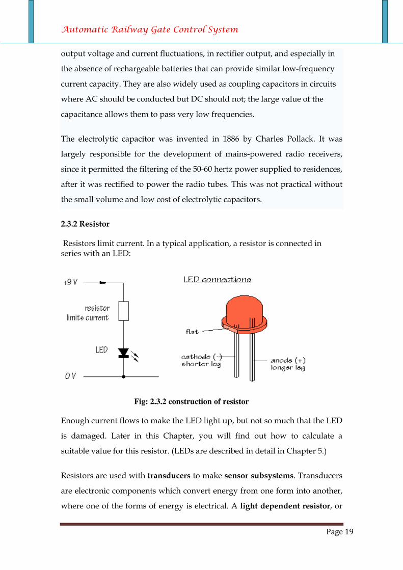
2.3.2 Resistor
Resistors limit current. In a typical application, a resistor is connected in series with an LED:
Fig: 2.3.2 construction of resistor
Enough current flows to make the LED light up, but not so much that the LED
is damaged. Later in this Chapter, you will find out how to calculate a
suitable value for this resistor. (LEDs are described in detail in Chapter 5.)
Resistors are used with transducers to make sensor subsystems. Transducers
are electronic components which convert energy from one form into another,
where one of the forms of energy is electrical. A light dependent resistor, or

Automatic Railway Gate Control System
Page 20
LDR, is an example of an input transducer. Changes in the brightness of the
light shining onto the surface of the LDR result in changes in its resistance. As
will be explained later, an input transducer is most often connected along
with a resistor to make a circuit called a potential divider. In this case, the
output of the potential divider will be a voltage signal which reflects changes
in illumination.
2.3.3 POWER SUPPLY:
To run the electronic gadget at home it is provided by some power supply.
The microcontroller used (at89c51) requires 12v D.C supply. The DTMF
receiver used (mt8870) requires 5v D.C. so design of these regulated power
supply is also an important part in hardware design. The A.C power supply
from mains is taken and regulated using the rectifiers. For design of a
regulated power supply components used are:
• Transformer.
• Diodes.
• Rectifiers.
• Regulated IC chips.
• Capacitive filters.
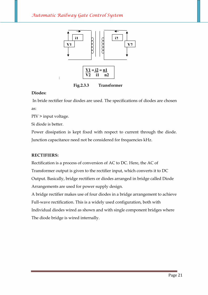
Trans former:
A transformer is required to couple the mains to the actual power supply
circuit. This is required to isolate the mains from the actual regulated power
supply circuit and the other part of the kit. This isolation eliminates the dame
of the kit to any power supply variations or from a faulty shock.
Automatic Railway Gate Control System
Page 21
:
Fig.2.3.3 Transformer
Diodes:
In bride rectifier four diodes are used. The specifications of diodes are chosen
as:
PIV > input voltage.
Si diode is better.
Power dissipation is kept fixed with respect to current through the diode.
Junction capacitance need not be considered for frequencies kHz.
RECTIFIERS:
Rectification is a process of conversion of AC to DC. Here, the AC of
Transformer output is given to the rectifier input, which converts it to DC
Output. Basically, bridge rectifiers or diodes arranged in bridge called Diode
Arrangements are used for power supply design.
A bridge rectifier makes use of four diodes in a bridge arrangement to achieve
Full-wave rectification. This is a widely used configuration, both with
Individual diodes wired as shown and with single component bridges where
The diode bridge is wired internally.
V1 V2
i1 i2
V1 = i2 = n1
V2 i1 n2
Automatic Railway Gate Control System
Page 22
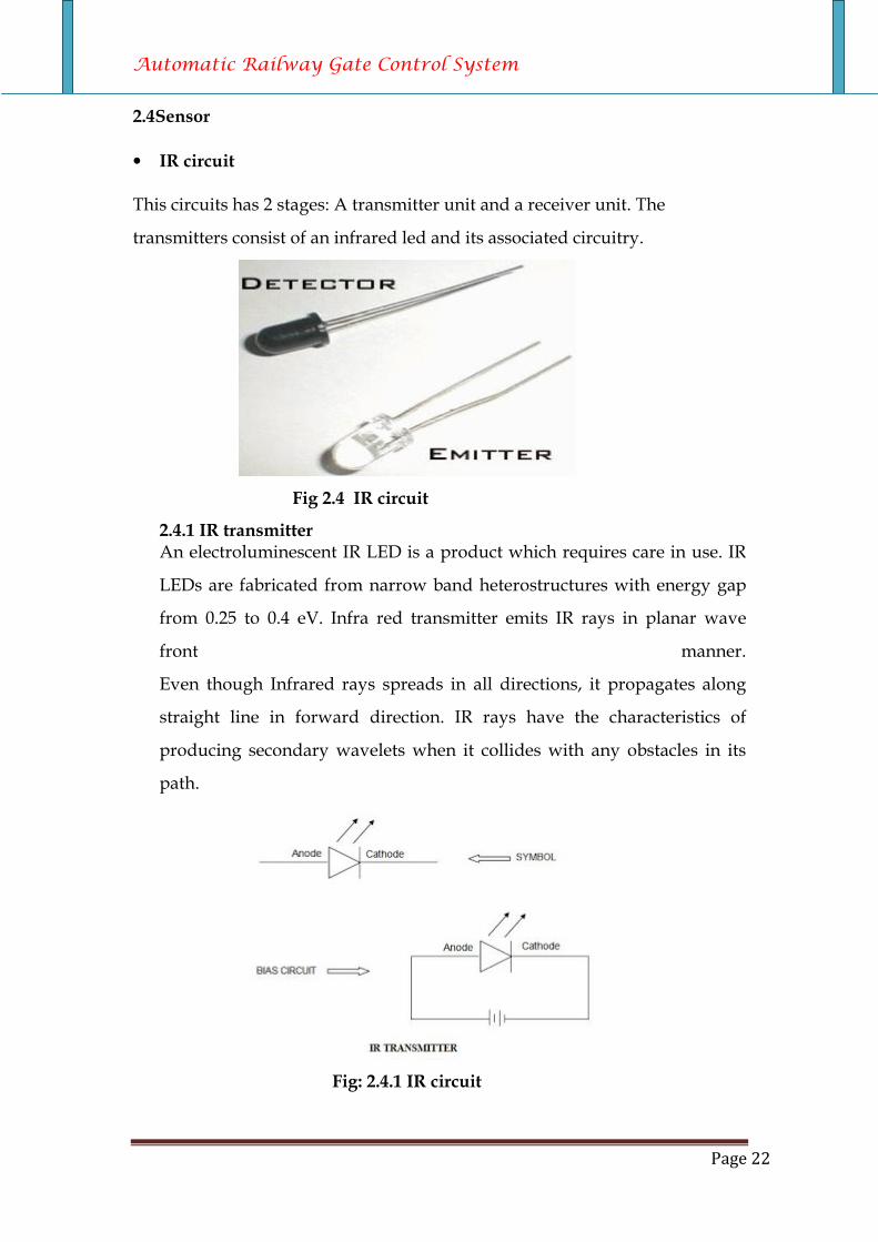
2.4Sensor
• IR circuit This circuits has 2 stages: A transmitter unit and a receiver unit. The
transmitters consist of an infrared led and its associated circuitry.
Fig 2.4 IR circuit
2.4.1 IR transmitter An electroluminescent IR LED is a product which requires care in use. IR
LEDs are fabricated from narrow band heterostructures with energy gap
from 0.25 to 0.4 eV. Infra red transmitter emits IR rays in planar wave
front manner.
Even though Infrared rays spreads in all directions, it propagates along
straight line in forward direction. IR rays have the characteristics of
producing secondary wavelets when it collides with any obstacles in its
path.
Fig: 2.4.1 IR circuit
Automatic Railway Gate Control System
Page 23
When IR rays gets emitted from LED, it moves in the direction it is angled.
When any obstacle interferes in the path, the IR rays get cut and it produces
secondary wavelets which propagates mostly in return direction or in a
direction opposite to that of the primary waves, which produces the net result
like reflection of IR rays
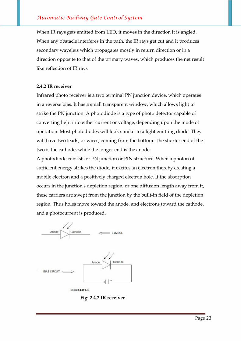
2.4.2 IR receiver
Infrared photo receiver is a two terminal PN junction device, which operates
in a reverse bias. It has a small transparent window, which allows light to
strike the PN junction. A photodiode is a type of photo detector capable of
converting light into either current or voltage, depending upon the mode of
operation. Most photodiodes will look similar to a light emitting diode. They
will have two leads, or wires, coming from the bottom. The shorter end of the
two is the cathode, while the longer end is the anode.
A photodiode consists of PN junction or PIN structure. When a photon of
sufficient energy strikes the diode, it excites an electron thereby creating a
mobile electron and a positively charged electron hole. If the absorption
occurs in the junction's depletion region, or one diffusion length away from it,
these carriers are swept from the junction by the built-in field of the depletion
region. Thus holes move toward the anode, and electrons toward the cathode,
and a photocurrent is produced.
Fig: 2.4.2 IR receiver
Automatic Railway Gate Control System
Page 24
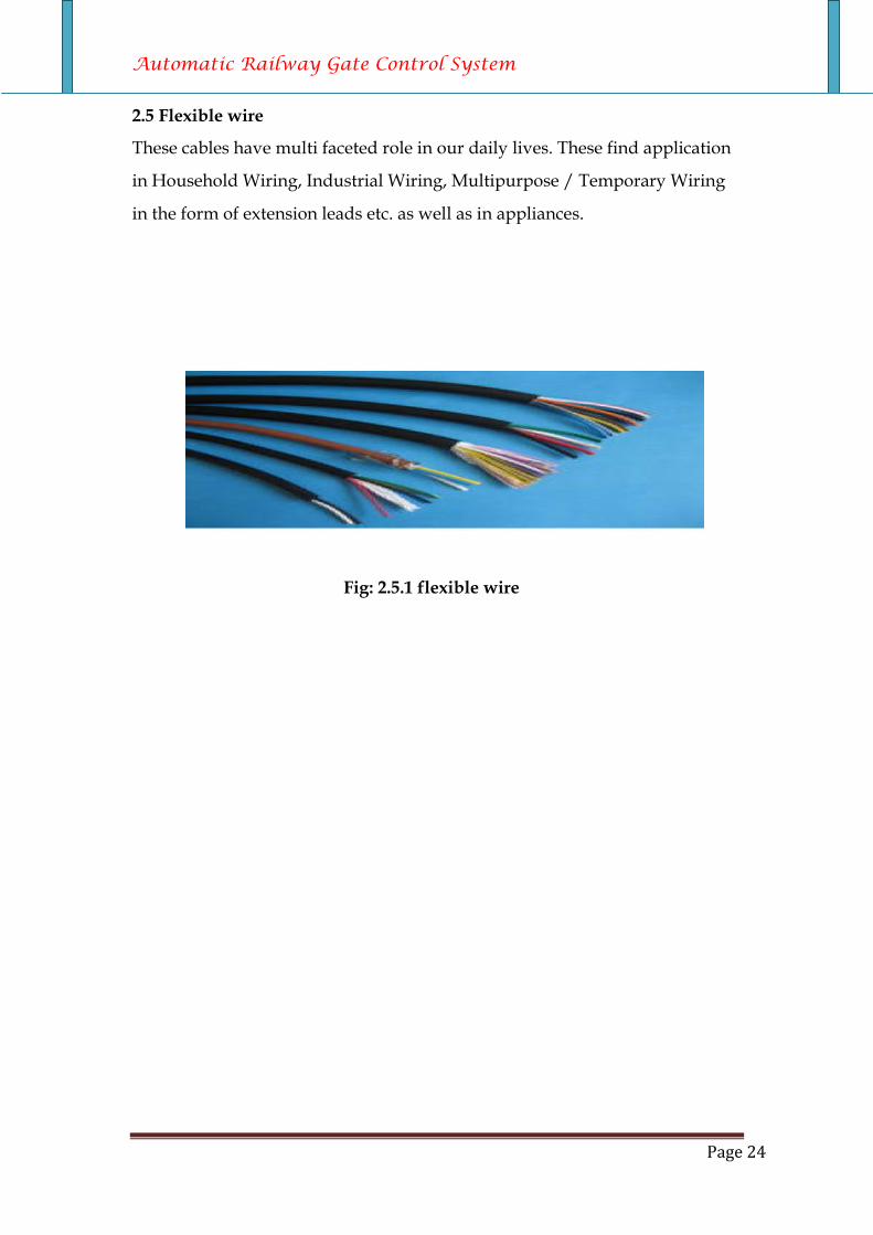
2.5 Flexible wire
These cables have multi faceted role in our daily lives. These find application
in Household Wiring, Industrial Wiring, Multipurpose / Temporary Wiring
in the form of extension leads etc. as well as in appliances.
Fig: 2.5.1 flexible wire
Automatic Railway Gate Control System
Page 25
Chapter: 3 Software system of automated railway crossing
Automatic Railway Gate Control System
Page 26
Chapter: 3 software system of automated railway crossing Introduction: Software development tools for the 8051 micro controller family support
every level of developer from the professional applications engineer to the
student just learning about embedded software development. The industry-
standard Kiel C Compilers, Macro Assemblers, Debuggers, Real-time Kernels,
and Single-board Computers support ALL 8051-compatible derivatives and
help you get your projects completed on schedule.
The source code is written in assembly language .It is saved as ASM file with
an extension. A51.the ASM file is converted into hex file using keil software.
Hex file is dumped into micro controller using LABTOOL software. At once
the file is dumped and the ROM is burnt then it becomes an embedded one.
Keil development tools for the 8051 Microcontroller Architecture support
every level of software developer from the professional applications engineer
to the student just learning about embedded software development.
The industry-standard Keil C Compilers, Macro Assemblers, Debuggers,
Real-time Kernels, Single-board Computers, and Emulators support all 8051
derivatives and help you get your projects completed on schedule
We can use this software to run our task, first we will make program in C
language. This program will use in this software to run our task.