automatic concrete sounder connor murphy elm 4702 3/24/14
TRANSCRIPT

Automatic Concrete Sounder
Connor MurphyELM 47023/24/14
Presentation Order• Background• Standard Testing Procedure• Electronic Testing Procedure• Problem• Proposed Solution• System Diagram• Time Delay (1)• Time Delay (2)• Mechanical• Timing Mechanism• Electrical• Programming (1)• Programming (2)• Project Goals Chronology• Budget• Questions?

Background• As concrete structures deteriorate,
the concrete must be monitored• Some testing requires sample of the
concrete but this is destructive• Non-destructive evaluation (NDE) is
a more popular method to test concrete. Examples of testing techniques for concrete and other materials include
Existing Testing Technology• Ground penetrating radar• Infrared evaluation• Sounding

Standard Testing Procedure
• Standard testing for bridges in Vermont is hammer and chain sounding
• Hammer strike against the concrete results in a sound whose pitch and ring tell whether the concrete is good or bad
• Technician sounds out “bad sections of concrete” to mark area of concrete to be replaced.

Speed of sound through materials
Sound travels at a given speed through different materials• A Person yells to two people, one person 10 ft away and one
100 ft away• The speed of sound in air is 1000 ft/s• The sound will reach the person who is 10ft away faster than
the person who is 100ft away • The time it took for the sound to travel is the time delay
Time delay 10ft away= (10 ft)/(1000ft/s)= .01sTime delay 100ft away= (100 ft)/(1000ft/s)= .1s
10ft
100ft
Problem
• Create an automated concrete sounder• Device must be able to determine concrete
depth and delaminations (cracks)• Device must be portable• Must be easy to use

Proposed Solution
• Solution will use a time delay based on the pulse echo standard
• Sound input will be a mechanized hammer; the start of measured time delay
• MEMs microphone will record concrete sound; this marks the end of the time delay
• Kinetis micro-controller will measure time delay and convert an outputted time in seconds
• Hammer and microphone will both be on top side of bridge
System DiagramInitially• Micro controls hammer• Reads, records data from microphones• Exports data to excel file on laptop
HammerMechanism
Microphones
Concrete Slab
Kinetis Micro
Cart

Time Delay (Thickness measurement)
Concrete Slab
Sound Paths-Concrete-Air only
Time (ms)
Volta
ge
Time (ms)
Volta
ge
Time (ms)Vo
ltage
Time Delay
Copper Plate
Slide Hammer
Scope Ch2Scope
Ch1
Scope Ch2Scope
Ch1
Scope Ch2Scope
Ch1
Timing Mechanism• Used for timing when
hammer hits copper plate
• Hammer completes circuit when contacting copper plate
• Normally open contact drives circuit low upon the hammer striking the copper
Energy In:PotentialE=mhgE=(.7kg)(.1524m)(9.807m/s)E= 1.04 J/s
Copper Plate
Hammer Slugm=.7kg
h= 6in =.1524m
To Micro
Time (ms)
Volta
ge
Hammer hits plate
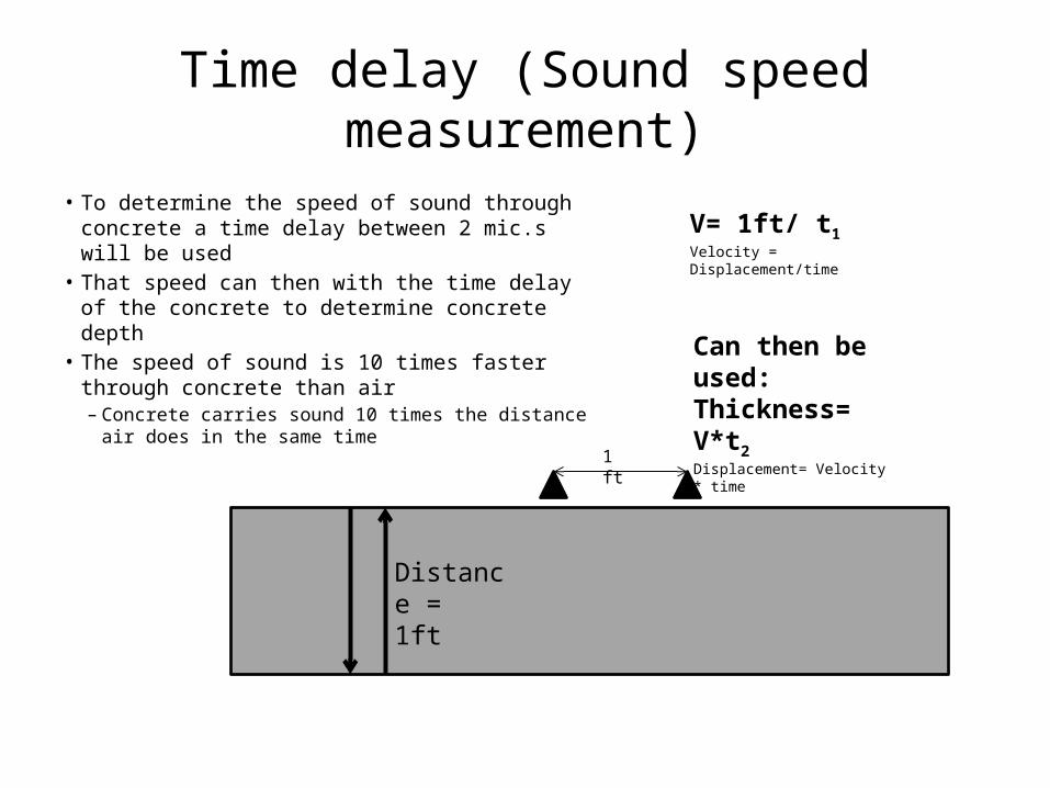
Time delay (Sound speed measurement)
• To determine the speed of sound through concrete a time delay between 2 mic.s will be used
• That speed can then with the time delay of the concrete to determine concrete depth
• The speed of sound is 10 times faster through concrete than air
– Concrete carries sound 10 times the distance air does in the same time
Distance =1ft
1 ft
V= 1ft/ t1Velocity = Displacement/time
Can then be used:Thickness= V*t2Displacement= Velocity * time

Mechanical
• Device tentatively to be contained on rolling cart.
• Weights to improve coupling between hammer and microphone on cart and bridge surface
• Specific plans to be developed for cart
• Cart will be similar in size to the chain drag cart shown
Weights
Cart
Hammer Mechanism
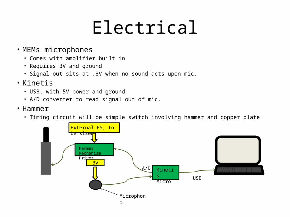
Electrical• MEMs microphones
• Comes with amplifier built in• Requires 3V and ground• Signal out sits at .8V when no sound acts upon mic.
• Kinetis• USB, with 5V power and ground• A/D converter to read signal out of mic.
• Hammer• Timing circuit will be simple switch involving hammer and copper plate
USB
Kinetis Micro
3VA/D
Hammer Mechanism Driver
External PS, to be sized
Microphone

Programming
Input pulse from
hammer
Read from microphones
& hammer circuit
Convert time delays to
inches
Output mic. Data to
computer
• Programming is in initial stages
• 4 general action concepts
• Programming will be in C
• Timing will be very critical so sound waves don’t interfere with one another

ProgrammingInput pulse from
hammer
•Hammer/ plate switch inititates program
Read from microphones & hammer circuit
•Data captured through A/D from microphone
Convert time delays to inches
•Will eventually correlate sound wave time delay with concrete thickness
Output mic. data to computer
•Data sent to computer•Computer logs data in Excel
Where• Desired sound wave---------• Cancelation wave------------• Unwanted reflected/
transmitted wave------------• Hammer------------------------
• Microphone--------------------
• Concrete Bridge Slab---------

Project Goals Chronology
Ordering MilestonesDate to be completed
Completed? Ordering Milestones
Date to be completed
Completed?
Milestone 1 Automated Sounding is plausible 2/7/2014 Milestone 3 Testing 4/18/2014Tasks Tasks
1 Simple sounding tests 1/24/2013 1 Demonstrated souding system prototype 3/28/2014A Speaker, microphone, floor test 2 Sounding system parameters 3/21/2014B Hammer, microphone, floor test A Concrete Sections
2 Budget estimate 2/7/2014 B Bridge Types
Milestone 2 Define Sounding solution parameters 3/14/2014 C Accuracy
Tasks 3 Refine Systems 3/28/20141 Calculate boundary losses (reflections, transmissions)1/31/2014 A Hammer Mechanism
2 Determine sound input (speaker, hammer, etc.) 1/31/2014 B Microphone
3 Size sound input 2/7/2014 C Data acquisition
4 Determine sound input and mic. Parameters 2/21/2014 D Cart/Packaging unit
A Distances Milestone 4 Completion 5/2/2014B Interfaces Tasks
C Coupling 1 Is project complete and functional? 4/11/20145 Refine System diagram 2 Is design work documented and organized? 4/25/20146 Software design (initial stage) 3/7/2014 3 Is presentation prepared? 4/18/2014
A Hammer mechanism state diagram 4 Is course documentation completed? 5/2/2014B Data acquisition state diagram
C Whole system diagram
7 Electrical design (initial stage) 3/7/2014A Hammer timing cicuit
B Hammer driver cicuit
C Microphone power/ data circuit
8 Mechanical/Project Packaging 3/7/2014A Hammer Mechanism
B Cart/Packaging unit
C Hammer/Mic coupling/postioning
9 Materials lists 3/7/2014
Automatic Concrete Sounder WBS
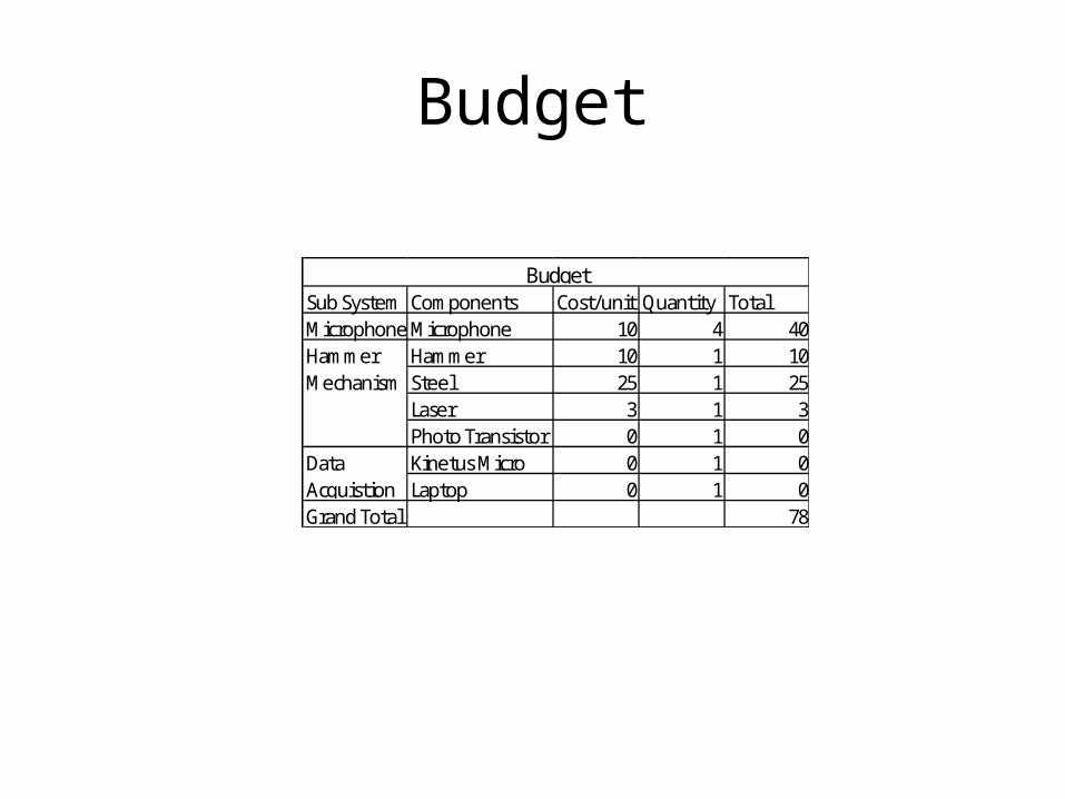
Budget
Sub System Components Cost/unit Quantity TotalMicrophone Microphone 10 4 40
Hammer 10 1 10Steel 25 1 25Laser 3 1 3Photo Transistor 0 1 0Kinetus Micro 0 1 0Laptop 0 1 0
Grand Total 78
Hammer Mechanism
Data Acquistion
Budget

Questions?
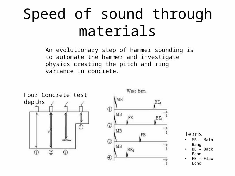
Speed of sound through materials
Terms• MB - Main Bang• BE – Back Echo• FE – Flaw Echo
Four Concrete test depths
An evolutionary step of hammer sounding is to automate the hammer and investigate physics creating the pitch and ring variance in concrete.